Article

Phase-Controlled Thyristor Sub-Synchronous Damper Converter for a Liquefied Natural Gas Plant

by
Lorenzo Bongini
1,
Rosa Anna Mastromauro
1,*,
Daniele Sgrò
2 and
Fabrizio Malvaldi
2
1
Department of Information Engineering (DINFO), University of Florence, 50139 Florence, Italy
2
Baker Hughes, 50127 Florence, Italy
*
Author to whom correspondence should be addressed.
Energies 2021, 14(17), 5238; https://doi.org/10.3390/en14175238
Submission received: 5 July 2021 / Revised: 16 August 2021 / Accepted: 22 August 2021 / Published: 24 August 2021
(This article belongs to the Section F: Electrical Engineering)

Abstract

:
In electrified liquefied natural gas (LNG) plants variable frequency drives (VFDs) interact with turbine-generator (TG) units creating torsional vibrations known as sub-synchronous torsional interactions (SSTIs). Torsional vibrations can be dangerous for an LNG plant when they involve torsional instability. The stability of an LNG plant depends on the plant configuration and on the number of TG units and of VFDs. In such peculiar configurations stability cannot be achieved acting of the VFDs control system. Alternatively, dedicated equipment is needed to damp the torsional vibrations. In this paper, a sub-synchronous damper (SSD) converter is used to mitigate the SSTI phenomena. The SSD converter consists of a thyristor H-bridge regulating the phase of the additional torque provided at the TG unit air-gap. A phase control system is proposed and is based on the torsional torque oscillations measurement. An adaptive reference signal is employed, also guaranteeing high performance in island-mode operation. The proposed solution increases the damping of the LNG plant in all the considered configurations. The LNG plant successful operation is validated by comprehensive results.

1. Introduction

Liquefied natural gas (LNG) plants frequently encounter torsional resonance phenomena when high power electrical motors are supplied by variable frequency drives (VFDs). This is due to the interactions among the VFDs and the turbine-generator (TG) units which cause torsional vibrations known as sub-synchronous torsional interactions (SSTIs) [1,2,3,4]. SSTI contingency has to be considered on the case of LNG plants’ transient operation such as load variations. An analysis of these phenomena with considerations about the stability of the LNG plants is presented in [1,2]. Nevertheless, SSTI phenomena have been experienced and studied previously in other applications, such as in wind farms [5,6].
In an LNG plant, SSTIs lead to instability when the TG unit’s overall electromechanical damping is negative [1,2]. The overall damping of a TG unit consists of mechanical damping and electrical damping [7]. The mechanical damping is positive while the electrical damping is influenced by the devices included in the electromechanical system and it can be negative. In [2], electrical damping assessment and sensitivity analysis are provided to evaluate the impact of the LNG plant’s control system-parameter’s variation on the SSTIs phenomena. The study is customized considering a real LNG plant operating in several configurations which differ in number of TG units, number of VFDs and TG unit power. In the same paper the authors demonstrated that a fine tuning of the control parameters should be adopted in LNG plants’ practice reducing the risk of torsional instability. However, in [2] it is also highlighted how, in such peculiar configurations, the SSTIs risk cannot be avoided by acting only on the tuning of the control system parameters.
In case the torsional stability cannot be achieved by varying the control system parameters, a dedicated power-electronics-based equipment can be included in the electromechanical system to solve instability. In literature, some solutions based on power converters have been adopted to manage sub-synchronous resonance (SSR) [8,9,10,11,12]. In [8,9] a thyristor-controlled series capacitor is introduced as an attractive method for SSR mitigation; while in [11], the performances provided by a thyristor-controlled series capacitor compensator are compared with the performances obtained using a series capacitor. In [12] an active damper based on a high-bandwidth power converter is employed. In particular, the active damper is located at the point of common coupling (PCC) modifying the equivalent impedance of the power network and mitigating the resonant phenomena. In [9] small-signal analysis is used to investigate the effects of a static synchronous compensator, originally installed to regulate the network voltage, on the power system oscillations.
With regard to SSTI phenomena, an active damper based on an adaptive active filter is proposed in [13] to increase the damping of the electro-mechanical vibrations. A thyristor power converter which increases the oscillation modes’ natural damping in the rotating shaft assembly is presented in [14]. The main differences of the methods in [13,14] are the input signals of the damper converter control system. In the first case, the input signal is derived from the electrical frequency of the generator stator current [13]; in the second one, the input signal is obtained by the generator rotor speed [14]. However, both methods exhibit high performances as concluded in [15].
Considering the LNG plant configurations examined in [2], in this paper a sub-synchronous damper (SSD) based on a thyristor rectifier is presented to mitigate torsional oscillations. The power converter is controlled to provide an additional torque oscillation at the air-gap of the TG unit, as introduced in [16] and developed in [17]. The additional torque can be expressed as the sum of the synchronous torque and the damped torque, in accordance with the complex torque coefficient method. As described in [18,19,20], the damped torque can be used to reduce the sub-synchronous oscillations, since it modifies the overall damping of the TG units. The damping increases or decreases according to the phase difference between the additional torque and the relative torsional speed of the TG unit.
It is common practice [13,17,21] to operate the SSD with a constant phase. Unfortunately, this approach allows for satisfying performance only for a set of the power system possible configurations. These results are unattractive in island-mode operation when the variability of the equivalent impedance is not negligible. For this reason, in this paper a new SSD phase control system is presented and characterized by an adaptive reference signal; in particular, the phase of SSD current reference is adjusted on the basis of the torsional torque oscillations measurement. As in [21], the SSD regulates the phase of the additional torque provided at the TG air-gap. Differently from [21], the amplitude of the torsional oscillations is used to estimate the TG overall damping and to determine the exact phase of the SSD current.
The rest of the paper is organized as follows: in Section 2 the case study is presented; in Section 3 the theoretical relationship between the electromechanical torque variation and electrical damping is investigated; in Section 4 the overall SSD control system is analyzed; Section 5 provides the results considering four different configurations of the plant; and finally, Section 6 is focused on final remarks.

2. Liquefied Natural Gas Plant: Case Study

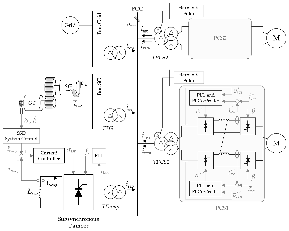
The LNG plant under analysis is shown in Figure 1. The considered power system consists of three identical TG units with an installed capacity of 44 MVA and two 16 MVA compression trains coupled to thyristor variable frequency drives (TVFDs). Furthermore, for each compression train a harmonic filter (HF) is connected to the point of common coupling (PCC) to compensate the harmonic currents of the TVFD. The circuits are designed to cut off the 5th, 7th and 11th harmonics. The plant operates in island mode with a PCC voltage ( v P C S ) equal to 30 kV. In order to simplify the analysis, the overall loads connected to the power system are taken into account through a lumped load. In Figure 1 the other TG units and the lumped load are represented by the generic block denoted as “Grid”. Table 1 reports the rated data related to the real LNG plant under analysis.
For the sake of simplicity, Figure 1 represents only one TG unit, that is composed of a gas turbine (GT) coupled through a gearbox to the synchronous generator (SG). The SG is connected to the PCC through a step-up transformer, denoted as TTG. As in [1,2], the control system of the SG includes an automatic voltage regulator (AVR) and a power system stabilizer (PSS) in compliance with [22].
The TVFDs, denoted as power conversion stage 1 (PCS1) and power conversion stage 2 (PCS2), supply two 6-phase synchronous motors (Ms). Ms act as starter and helper motors, allowing start-up of the entire compression train and providing additional power when required. Each TVFD is connected to the PCC through a step-down transformer with two secondary windings. The step-down transformers are indicated with TPCS1 and TPCS2. Each TVFD consists of two line-commutated-converters (LCCs). Each LCC is a double-stage converter since the first stage is a line-commutated-rectifier (LCR), while the second stage is a line-commutated-inverter (LCI). The control scheme of the TVFD first stage is depicted in Figure 1. The DC-link currents are controlled by means of two PI controllers which set the firing angles α′ and α″. In contrast, the second stage of the TVFD operates with constant firing angles denoted as β. Two phase locked loops (PLLs) provide synchronization with the voltages v P C S and v P C S . Further details can be found in [1,2].
In [2], it was highlighted that high risk related to SSTI phenomena is verified when only one TG unit supplies the entire power system. For this reason, in this paper an SSD converter is connected to the PCC through the step-down transformer (TDamp) to reduce the TG unit sub-synchronous torsional oscillations.
The SSD converter consists of an H-bridge based on thyristors and of an LSSD inductance. The current provided by the SSD converter at the DC-link is denoted as iDamp. It can be expressed as the sum of a direct component (IDamp) and superimposed oscillations. It results in:
i D a m p ( t ) = I D a m p + a h + s i n ( w h t + φ h ) ,
where ah, ωh and φh represent, respectively, the magnitude, the angular frequency and the phase of each current oscillation at the DC-link.
As discussed in [3], torque oscillation with angular frequency ωh is verified at the TG air-gap. As a consequence, TG torsional damping at the frequency fh can be related to the oscillation of the current iDamp at the same frequency.

3. Electromechanical Torque Variation and Electrical Damping

The TG unit shown in Figure 1 can be described by a lumped model characterized by 59 degrees of freedom (DOFs). The shaft torsional dynamics are defined by the system of differential equations based on Newton’s second law. It results in:
J δ ¨ _ + R δ ˙ _ + K δ _ = T _ ,
where δ is the DOF angle vector, J is the inertia diagonal matrix, K is the tri-diagonal stiffness matrix, R is the damping matrix and T is the vector of the torque applied to the TG shaft. The vector T includes the driving torque TGT and the SG electromechanical torque TE.
In order to simplify, the torsional study of the TG shaft, (2) is expressed through modal analysis. Considering the coordinate transformation expressed in (3), the modal approach [23,24,25,26] allows obtaining a system of uncoupled equations. It results in:
q _ = Φ 1 δ _ ,
j q ¨ _ + r q ˙ _ + k q _ = Φ T ( T _ G T T _ E ) ,
with
j = Φ T J Φ ,
r = Φ T R Φ ,
k = Φ T K Φ ,
where q _ is the vector of the modal coordinates and Φ is the eigenvectors matrix of the J 1 K matrix.
Considering the complex torque coefficient method [18,19,20] and evaluating the results obtained in [1,2], how the modal electric torque ΦTTE at the generic TNF is linked to the damping can be assessed. In particular, small-signal analysis is carried out on the modal coordinate ΔqTNF. The relative speed deviation can be obtained through the time derivative (8). The electromagnetic torque increment can be expressed as the sum of the synchronous torque and the damped torque (9). It results in:
Δ q ˙ T N F = d d t Δ q T N F ,
Φ _ T N F T Δ T _ E = k e ( T N F ) Δ q T N F + r e ( T N F ) Δ q ˙ T N F ,
where Φ _ T N F T is the row vector of Φ _ T related to the generic TNF and ke(TNF) and re(TNF) are the stiffness coefficient and the damping coefficient. These coefficients are dependent on all the devices included in the electromechanical system (TG units, power conversion stages, HFs, lumped load and SSD).
Neglecting the modal driven torque contributes ΦTTGT, (9) can be replaced in (4). For the generic TNF the torsional dynamics can be represented by the following equation:
j ( T N F ) Δ q ¨ T N F + ( r m ( T N F ) + r e ( T N F ) ) Δ q ˙ T N F + ( k m ( T N F ) + k e ( T N F ) ) Δ q T N F = 0 ,
where j(TNF), rm(TNF) and km(TNF) are, respectively, the diagonal element of the modal inertia matrix j, the modal damping matrix r and modal stiffness matrix k (for the considered TNF). They depend solely on the mechanical characteristics of the TG.
It can then be pointed out that ke(TNF) influences the value of the TG natural frequency while re(TNF) influences the damping value associated to the TG unit. It represents an extension of what is discussed in [1,2].
The electromechanical torque variation ( Φ _ T N F T Δ T _ E ) due to the modal speed oscillation ( Δ q ˙ T N F ) can be evaluated starting with (9). It results in:
Φ _ T N F T Δ T _ E Δ q ˙ T N F = r e ( T N F ) i 1 ω T N F k e ( T N F ) .
Equation (11) consists of two terms which can be expressed as the function of φ T N F , where φ T N F is the angle between the electromechanical torque oscillation and the torsional speed oscillation:
r e ( T N F ) = | Φ _ T N F T Δ T _ E Δ q ˙ T N F | c o s ( φ T N F ) ,
k e ( T N F ) = | Φ _ T N F T Δ T _ E Δ q ˙ T N F | s i n ( φ T N F ) ω i .
Since the electrical damping ξe(TNF) can be defined as:
ξ e ( T N F ) = r e ( T N F ) 2 π T N F ,
the electrical damping ξe(TNF) is positive, and the torsional instability is avoided, when the phase φ T N F is in the range of 90–270°. If φ T N F exceeds this range, ξe(TNF) becomes negative.
Considering the homogeneous equation associated with (2), a preliminary analysis of the TG unit can be developed. The TG unit has two sub-synchronous TNFs below the network rated frequency (fn = 50 Hz): TNF1 = 9.2 Hz and TNF2 = 31.5 Hz. Hence, the sub-synchronous torsional dynamics are assessed through (4) where the matrixes j, r and k are calculated using the parameters reported in Table 2. It has to be considered that the rigid component of the TG shaft line is denoted as j(0). Looking at Table 2, all the data are related to the real LNG plant under analysis and they are provided by Baker Hughes mechanical engineering department.

4. Sub-Synchronous Damper (SSD) Converter and Control System

In order to increase the electrical damping of the TG units and to avoid torsional instability, a dedicated converter is connected to the PCC (Figure 1). The SSD consists of an LCR operating at the grid frequency fn.
The SSD converter is controlled to provide an additional torque oscillation ΔTSSD increasing the electrical damping. In accordance with (12), ΔTSSD mitigates the sub-synchronous oscillations only if the phase shift φ T N F , related to the speed oscillation ΔωSG, is within the range of 90–270°.
Considering the dynamics associated with the generic TNF, the phase difference φ T N F between the speed oscillation ΔωSG and the additional torque oscillation ΔTSSD is composed of three contributors. The first one is denoted as φ S G and it represents the phase difference between the additional torque oscillation ΔTSSD and the stator current oscillation Δ i _ S G , measured in a synchronous reference frame rotating at the grid pulsation ωn. The second one is denoted as φ P C C and it is the phase difference between the stator current oscillation Δ i _ S G and the SSD current oscillation Δ i _ S S D . φ P C C depends on the equivalent impedance of the plant and by the plant configuration. The third one is denoted as φ S S D and it represents the phase difference between the SSD converter reference current i D a m p and the speed oscillation ΔωSG. It results in:
φ T N F = φ S G + φ P C C + φ S S D .
As a consequence, the SSD control system is designed to include a phase control system determining the proper value of φ S S D . The proper value of φ S S D has to verify the following condition at each sub-synchronous oscillation frequency:
90 ° φ T N F 270 ° .
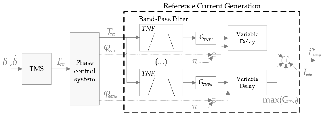
Starting from the measurements of the DOF angle vector and torsional speed ( δ _ and δ ˙ _ ), the torsional monitoring system (TMS) allows achieving the ΔωSG of the turbine toothed wheel at the point of measurement [27]. The resulting alternating torque ΔTTG expressed per-unit is calculated on the basis of the detailed torsional model of the shaft-line and it is used to generate the proper SSD converter reference current i D a m p . The reference current i D a m p represents the desired SSD DC-link current. The signal i D a m p can be expressed as:
i D a m p ( t ) = ( 1 + Δ T T G ( t + φ S S D + 180 ° T N F ) ) G T N F + I m i n ,
where Imin is a constant value set in order to avoid discontinuous conduction of the LCR, φ S S D is provided by the SSD phase control system (Figure 2) and GTNF is a proportional gain designed to guarantee sufficient damping.
The current reference i D a m p is generated by the reference current generation (RCG) block in the SSD control system shown in Figure 2.
Looking at Figure 2, for each sub-synchronous TNF, a band-pass filter is applied to the TTG signal. The natural frequencies, characterizing the band-pass filters, are selected considering the preliminary assessment with regards to the homogeneous equation associated to (4). These frequencies can be considered fixed, because each TNF is mainly determined by the mechanical parameters of the TG units. The appropriate compensation phases φ S S D 1 , φ S S D 2 , etc., for different TNFs, can be considered as decoupled signals, which represent the outputs of the phase control system and the inputs of the RCG block. The phase shifts are sufficient to satisfy the condition in (16) for the corresponding frequencies. The proportional gain for each mode (GTNF1, GTNF2, etc.) has to be tuned in order to provide proper damping torque for SSTI phenomena reduction.
Finally, looking at Figure 1, a PI current controller determines the firing angle of the SSD converter, denoted as α S S D , which is used to regulate the current i D a m p on the DC-link. A PLL guarantees synchronization with the voltage v S S D at the secondary side of the transformer TDamp.
The proper tuning of the SSD current controller parameters (KSSD and TSSD) is achieved through the zero-pole placement method considering that the LCR model is derived on the basis of the 12-pulse H-bridge rectifier model developed in [2]. The electrical and control system parameters of the proposed SSD are reported in Table 3.
Considering the generic TNF, it could be possible to adopt a simpler control strategy as previously proposed in [13,17,21] where: a constant value of φ S S D is set to verify the condition in (16); φ S G could be exactly determined through the SG electrical parameters; and φ P C C could be estimated, for example, through time-domain simulation software [17]. However, the assessment of φ P C C depends on the equivalent network impedance. Hence, the methods described in [10,14,18] do not allow maximizing of the damping related to the additional torque ΔTSSD working with a constant φ S S D value.
Starting from this consideration, the phase control proposed in this paper allows improving of the SSD converter operation. The phase control is included in the SSD control system as shown in Figure 2 and it is analyzed in detail in the following subsection. The phase control system regulates φ S S D in order to achieve a phase difference φ T N F = 180 ° . This condition maximizes the electrical damping with reference to (12) and (14).

Phase Control System

The phase control system is based on the estimation of the damping matrix component r(TNF) starting from the torque signal TTG. In particular, at the SG mid-section, the angular displacement Δδi is measured and this measurement is used to calculate the torque TTG. It results in:
T T G = Δ δ i K i ,
where Ki is the stiffness coefficient related to the angular displacement Δδi.
In a modal representation, the torsional behavior of the TG unit is described by a homogeneous differential (10). Assuming that ke(TNF) is negligible compared to km(TNF), the sub-synchronous dynamics of the generator unit are represented at the frequency TNF by the following motion equation:
Δ q T N F ( t ) = e r ( T N F ) 2 j ( T N F ) t | Δ q T N F | c o s ( 2 π T N F t ) ,
with
r ( T N F ) = r m ( T N F ) + r e ( T N F ) ,
and where | Δ q T N F | is the module relative to the angular displacement which depends on the boundary conditions. The modal transformation expressed in (3) and Equation (18) can be used to express the oscillation of the torque TTG as a function of the modal variables.
Considering the eigenvectors matrix Φ defined as:
Φ = [ Φ 1 , 0 Φ 1 , 1 Φ 1 , T N F Φ i 1 , 0 Φ i 1 , 1 Φ i 1 , T N F Φ i , 0 Φ i , 1 Φ i , T N F Φ 59 , 0 Φ 59 , 1 Φ 59 , T N F ] ,
the torque oscillation at the frequency TNF can be expressed as:
Δ T T G ( T N F ) = K i ( Φ i , T N F Φ i 1 , T N F ) Δ q T N F ,
Combining (19) and (22), it results in the envelope related to the torque oscillation (|ΔTTG(TNF)|) having the same exponential trend of the modal variable q T N F :
| Δ T T G ( T N F ) | = K i ( Φ i , T N F Φ i 1 , T N F ) | Δ q T N F | e r ( T N F ) 2 j ( T N F ) t
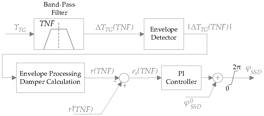
As shown in Figure 3, the calculated torque TTG is filtered by a band-pass filter in order to obtain the oscillation ΔTTG(TNF) at the considered TNF. The measured torque is processed to obtain its envelope and, on the basis of (23), the damping matrix component r(TNF) is estimated as follows:
r ( T N F ) = 2 j ( T N F ) d d t ( ln ( | Δ T T G ( T N F ) | ) ) .
The reference signal r ( T N F ) represents an input signal for the phase control system. The phase control is based on a PI controller which processes the error signal e r ( T N F ) . The proportional gain and the integral time constant of the PI controller are denoted as KPC and TPC, respectively.
In order to maximize the damping provided by the SSD, the signal reference r ( T N F ) has to be calculated considering the maximum achievable electrical damping. Denoting the maximum electrical damping as ξeMAX(TNF), r ( T N F ) can be expressed as:
r ( T N F ) = ( ξ e M A X ( T N F ) + ξ m ( T N F ) ) 2 π T N F
where ξm(TNF) is the mechanical damping at the considered TNF of the TG unit and it depends only on the mechanical parameters.
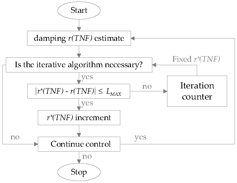
It should be considered that the value of ξeMAX(TNF) is not commonly known a priori. It depends on known values such as the amplitude of the iSSD current fluctuations and on unknown values such as the power network equivalent impedance. Hence, the reference r ( T N F ) can be varied according to an iterative algorithm designed to optimize the SSD damping action.
The adaptive reference can be generated considering the flowchart shown in Figure 4. The damping coefficient r(TNF) is acquired with the desired sampling rate. r(TNF) is then compared with r ( T N F ) . If the error signal ( e r ( T N F ) ) is higher than the maximum permissible error LMAX, the reference value is not varied, and the system converges to the desired damping value. Otherwise, the damping value must be adjusted to find the maximum achievable damping. The algorithm stops when the iterations counter registers that the settling time of the phase control is higher than TMAX. TMAX denotes a time constant tuned depending on the electro-mechanical system dynamics. When this condition is verified, the reference signal is maintained constant and it is set equal to the value determined at the previous iteration. This value corresponds with the highest damping which can be provided by the system.
The number of interactions required to achieve the algorithm convergence depends on the SSD power and the initial value of the signal r ( T N F ) .

5. Results

Four operative configurations (Cs) of the LNG plant shown in Figure 1 are analyzed. The configurations mainly differ in the number of TG units connected to PCC, the power of the lumped load and the PCSs number.
In Table 4 the power stage parameters related to the four considered configurations are shown. The other electrical data were already shown in Table 1.
The overall damping ξ(TNF1) of the TG units related to the first TNF is estimated as in [2]. The relation between ξ(TNF1) and the element r(TNF1) of the modal damping matrix r can be expressed in a similar way to that done in (14). The related mechanical parameters were already reported in Table 2. The estimated damping of the TG units in the four configurations is reported in Table 5.
In order to assess the SSD operation with regard to SSTI phenomena, a complete simulation platform is developed firstly using Simulink and Plecs toolboxes and subsequently using DigSILENT PowerFactory software. All the models included in the simulation platform are developed using the data provided in the previous tables and, in particular, considering the SSD converter electrical and control system parameters provided in Table 3.

5.1. Phase Control System Performance Evaluation

The first results are related to the phase control system performance evaluation. In order to test the phase control system, simulations are carried out for the configuration CA. In this case, the TG unit supplies an overall load whose power is 54% of the rated power. In particular, PCS1 is connected to a motor-compression train. A low voltage load is present in the power system and it is modeled through a generic RL load. The proposed phase control system parameters are tuned on the basis of the pole-zero placement and they are reported in Table 6.
Denoting ti as the instant when a torque impulse is applied and tON as the instant when the SSD converter is enabled, the system is considered in steady state until ti = 1 s. At ti, a torque impulse (which approximates a Dirac delta) is applied to the TG unit to emulate a perturbation action. Hence, the entire spectrum of frequencies is excited simultaneously. Contrarily, at tON = 6 s the SSD is enabled and the SSD converter operates modifying the overall damping. In particular, the phase control system determines the angle φ S S D assessed to achieve torsional stability.
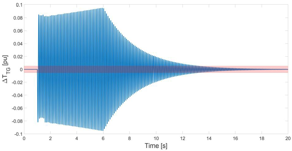
Figure 5 shows the torque oscillation ΔTTG related to the first TNF with and without the action of the SSD converter controlled with the proposed control system. It is possible to observe that no torque fluctuations are experienced up to ti = 1 s, when the torque impulse is applied. At this instance the torque magnitude jumps to 0.085 pu and it increases progressively until the insertion of the SSD converter. The SSD converter insertion reduces the torque oscillation at 5% of the initial value in 5.9 s. In Figure 5, the limit of 5% is marked with a red area.
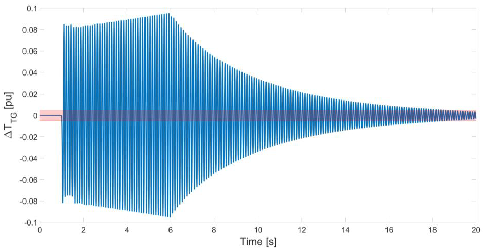
Assuming the same operating conditions, the performance of the proposed control method is compared with the results related to the damping techniques presented in [14,17]. The main difference between the proposed SSD control system (Figure 2) and the methods used [14,17] is the adaptive reference phase control. In particular, in [14,17] the phase φ S S D is fixed to verify the condition in (16) in the most common configurations of the plant. Furthermore, in [17] no dedicated power converter is employed to mitigate the SSTI phenomena. Contrarily, the additional torque ΔTSSD (at the SG air-gap) is generated acting on the DC-link current ( i D C ) of the plant power conversion stage.
Figure 6 and Figure 7 show the torque oscillation ΔTTG obtained by adopting, respectively, the methods in [14,17]. It can be observed that the proposed adaptive reference phase control method allows obtaining a better dynamic performance than the other two techniques. Indeed, in Figure 6 the torque oscillation is reduced at 5% of the initial value in 7.4 s, while in Figure 7 in 12.8 s.
The steady-state results related to the proposed method and the technique used in [14] are comparable. Contrarily, the damping achievable with the approach in [17] is limited.
Finally, it should also be highlighted that, the approaches in [14,17] operate with a fixed value of φ S S D while the proposed phase-controlled damper converter operates with a variable reference phase to obtain the maximum damping.
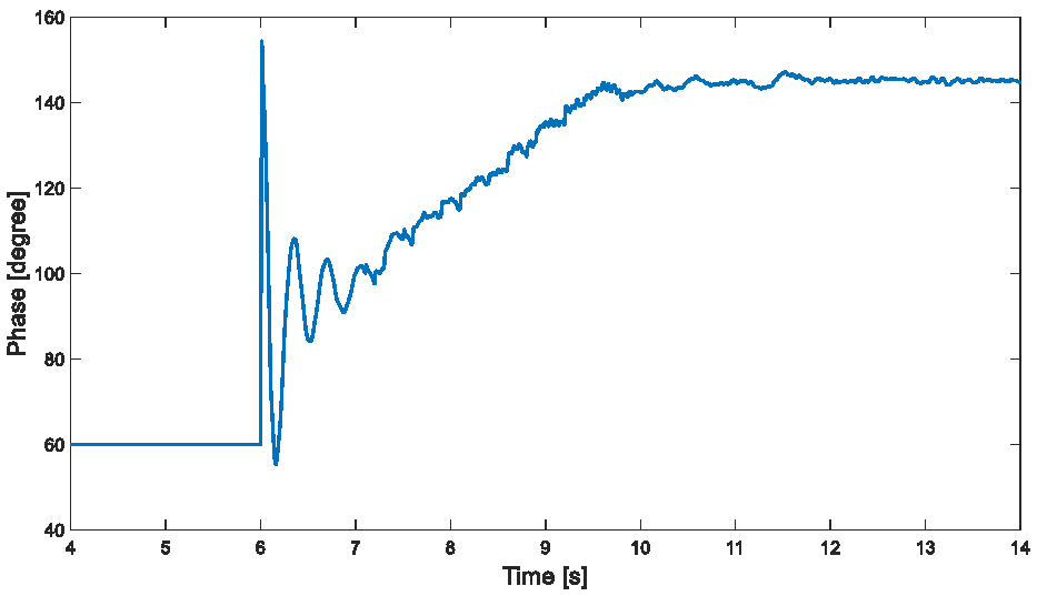
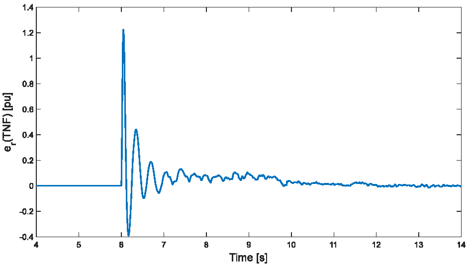
Considering the SSD converter control system proposed in this paper, in Figure 8 and Figure 9 the phase φ S S D and the phase error are shown, respectively. The reference signal r ( T N F 1 ) is generated by the iterative algorithm shown in Figure 4. The algorithm converges after 11 iterations which corresponds to a time of about 4 s. At tOFF = 10 s the maximum value of the damping coefficient is achieved. The reference signal is then constantly maintained and the phase control system ensures that the error signal is canceled (Figure 9).
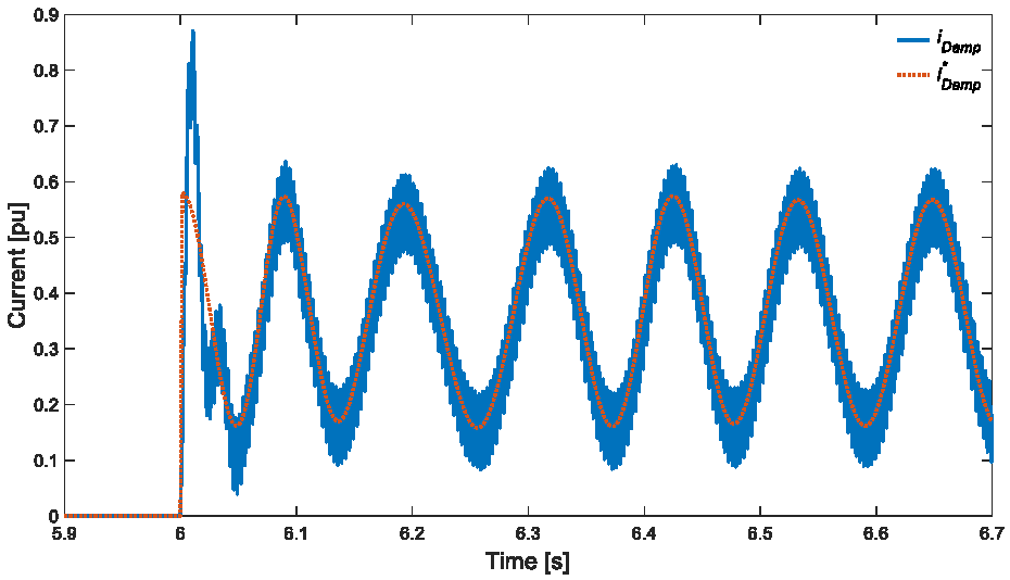
Finally, Figure 10 shows the comparison between the SSD current i D a m p and the current reference i D a m p in the 5.9–7 s time range. Tracking capability of the SSD current controller is verified. Looking at the current waveform i D a m p , the harmonic component at 300 Hz, typical of the H-bridge rectifier operation, and the component at the first TNF according to (17), can also be recognized.

5.2. Analysis of the SSD Converter Performance in Different LNG Plant Configurations

In the previous subsection, it was pointed out that the proposed SSD control system exhibits high dynamic performance. Indeed, when the SSD converter is enabled, the torsional oscillations are detected and reduced in a few seconds, as shown in Figure 5.
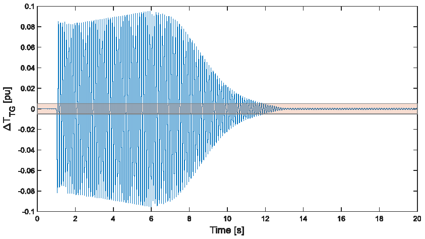
The four operative configurations shown in Table 4 are analyzed. In contrast with the previous case, the simulations are performed stressing the shaft line of a TG unit at ti = 0 s with a torque impulse and enabling the SSD at tON = 1 s. In this analysis, the times ti and tON are selected in order to reduce the computation burden of the simulation platform.
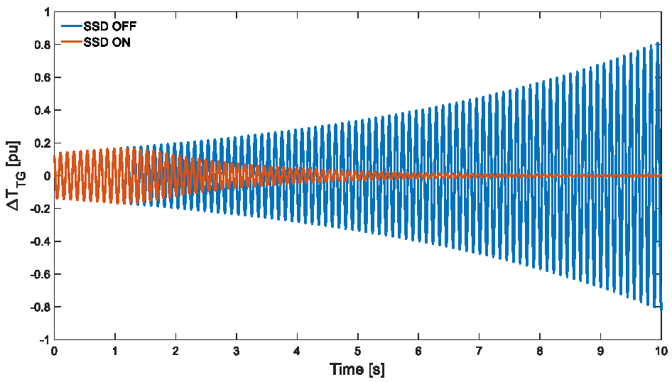
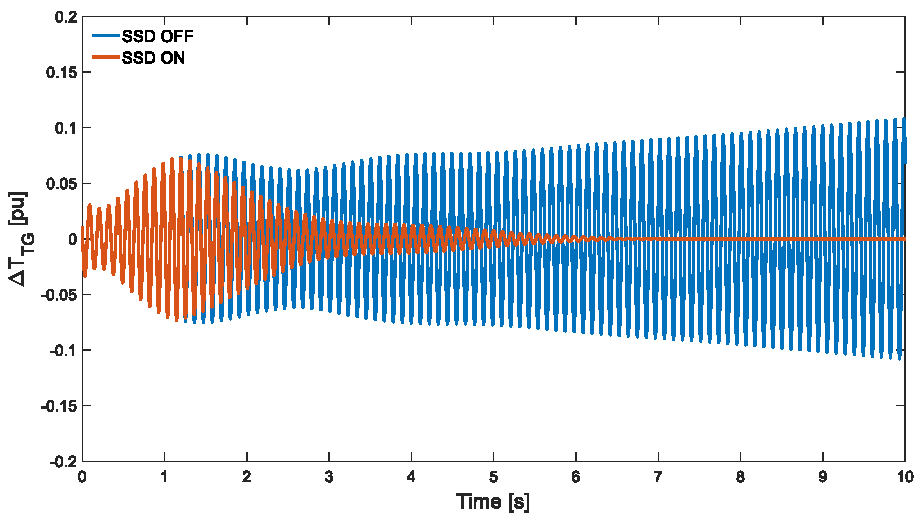
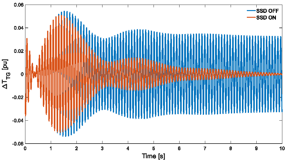
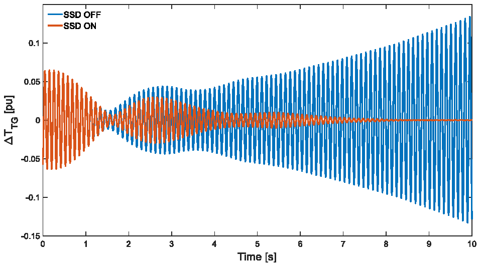
In Figure 11, Figure 12, Figure 13 and Figure 14 the results related to the torque oscillations ΔTTG (at the first TNF) in all the considered configurations are shown. In all these figures, two signals can be detected. The first one, characterized by a blue line denoted as “SSD OFF”, shows the torque oscillation when the SSD is disabled. The second one, characterized by an orange line and denoted as “SSD ON”, shows the torque oscillations when the SSD is enabled and it mitigates the torsional oscillation.
When the SSD is not enabled, it can be noticed that the amplitude of the torque oscillations is compatible with the overall damping reported in Table 5. In particular, the torsional damping ξ(TNF1) associated with the configurations CA (Figure 11), CB (Figure 12) and CD (Figure 14) has a negative value and the related torque oscillations grow with time. In contrast, the damping of the configuration CC (Figure 13) has a positive value and the system is stable since the torque oscillations do not grow with time in the absence of the SSD converter action. This favorable condition is verified since in configuration CC the number of TG units is high (3 TG units) and the overall load (including the number of TVFDs) is low [1,2].
In conclusion low damping values correspond to high torque oscillations. In particular, the configuration CA is characterized by the lowest value of ξ(TNF1) and the highest torque oscillation ΔTTG since it increases up 0.8 pu in about 10 s (Figure 11).
Furthermore, in the cases where multiple TG units are connected to the PCC, as it occurs in configurations CB, CC and CD, the proposed SSD converter allows achieving proper damping (Figure 12, Figure 13 and Figure 14). Hence proper operation of the proposed SSD converter and its control system is verified. However, it should be considered that, when more TG units are present in the plant (configurations CB, CC and CD), the SSD operates measuring the torsional torque of a sole TG. For this TG, the SSD provides an additional torque ΔTSSD at the air-gap of the SG and the phase difference is φ T N F 1 = 180° (maximum electrical damping). The same additional electrical torque is applied for all the other TG units but with other phase differences.
Looking at Figure 12, Figure 13 and Figure 14, it can be concluded that, in presence of more TG units, the SSD also provides satisfying performance. However, in these configurations the SSD cannot guarantee the maximum damping for all the TGs, hence certain torque oscillations can be detected at frequencies different from the first TNF.

6. Conclusions

The torsional stability of an LNG plant depends on the plant configurations. Starting from a condition of torsional instability, sometimes the torsional stability can be achieved by acting on the control system parameters of the LNG plant power conversion stages. In other cases, a dedicated equipment is required to damp the torsional oscillations. In this paper an SSD converter is proposed for torsional oscillations mitigation. The SSD is based on a phase-controlled LCR which increases the electrical damping of the LNG plant ensuring torsional stability. Different from solutions previously published in literature, the proposed SSD operates with a variable firing angle which is tuned to maximize the additional damping. The proposed control method exhibits satisfactory results in all the considered configurations.

Author Contributions

Conceptualization, L.B.; methodology, R.A.M.; software, L.B.; resources, D.S.; data curation, D.S.; writing—original draft preparation, L.B. and R.A.M.; writing—review and editing, L.B., R.A.M., D.S., F.M.; supervision, R.A.M.; project administration, F.M. All authors have read and agreed to the published version of the manuscript.

Funding

This research received no external funding.

Institutional Review Board Statement

Not applicable.

Informed Consent Statement

Not applicable.

Conflicts of Interest

The authors declare no conflict of interest.

References

  1. Bongini, L.; Mastromauro, R.A.; Sgrò, D.; Malvaldi, F. Electrical Damping Assessment and Stability Considerations for a Highly Electrified Liquefied Natural Gas Plant. Energies 2020, 13, 2612. [Google Scholar] [CrossRef]
  2. Bongini, L.; Mastromauro, R.A.; Sgrò, D.; Malvaldi, F. Electrical Damping Assessment and Sensitivity Analysis of a Liquefied Natural Gas Plant: Experimental Validation. Energies 2020, 13, 4084. [Google Scholar] [CrossRef]
  3. Bongini, L.; Mastromauro, R.A. Sub-Synchronous Torsional Interactions and Start-Up Issues in Oil&Gas Plants: A Real Case Study. In Proceedings of the 2019 AEIT International Annual Conference (AEIT), Florence, Italy, 18–20 September 2019; pp. 1–6. [Google Scholar]
  4. Schramm, S.; Sihler, C.; Song-Manguelle, J.; Rotondo, P. Damping Torsional Interharmonic Effects of Large Drives. IEEE Trans. Power Electron. 2010, 25, 1090–1098. [Google Scholar] [CrossRef]
  5. Gao, B.; Zhang, R.; Li, R.; Yu, H.; Zhao, G. Subsynchronous Torsional Interaction of Wind Farms with FSIG Wind Turbines Connected to LCC-HVDC Lines. Energies 2017, 10, 1435. [Google Scholar] [CrossRef] [Green Version]
  6. Li, P.; Wang, J.; Xiong, L.; Wu, F. Nonlinear Controllers Based on Exact Feedback Linearization for Series-Compensated DFIG-Based Wind Parks to Mitigate Sub-Synchronous Control Interaction. Energies 2017, 10, 1182. [Google Scholar] [CrossRef] [Green Version]
  7. Proposed Terms and Definitions for Subsynchronous Oscillations. IEEE Trans. Power Appar. Syst. 1980, PAS-99, 506–511. [CrossRef]
  8. Baker, D.H.; Boukarim, G.E.; D’Aquila, R.; Piwko, R.J. Subsynchronous Resonance Studies and Mitigation Methods for Series Capacitor Applications. In Proceedings of the Inaugural IEEE PES 2005 Conference and Exposition in Africa, University of KwaZulu-Natal, Durban, South Africa, 11–15 July 2005; pp. 386–392. [Google Scholar]
  9. Wang, H.F. Applications of Damping Torque Analysis to STATCOM Control. Int. J. Electr. Power Energy Syst. 2000, 22, 197–204. [Google Scholar] [CrossRef]
  10. Song, J.; Oh, S.; Lee, J.; Shin, J.; Jang, G. Application of the First Replica Controller in Korean Power Systems. Energies 2020, 13, 3343. [Google Scholar] [CrossRef]
  11. Tran, M.-Q.; Dinh, M.-C.; Lee, S.-J.; Lee, J.-I.; Park, M.; Lee, C.H.; Yoon, J. Analysis and Mitigation of Subsynchronous Resonance in a Korean Power Network with the First TCSC Installation. Energies 2019, 12, 2847. [Google Scholar] [CrossRef] [Green Version]
  12. Wang, X.; Blaabjerg, F.; Liserre, M.; Chen, Z.; He, J.; Li, Y. An Active Damper for Stabilizing Power-Electronics-Based AC Systems. IEEE Trans. Power Electron. 2014, 29, 3318–3329. [Google Scholar] [CrossRef]
  13. Saeed, P. Active Damping of Torsional Vibrations Due to the Sub-Harmonic Instability on a Synchronous Generator. In Proceedings of the 2018 20th European Conference on Power Electronics and Applications (EPE’18 ECCE Europe), Riga, Latvia, 30 October 2018. [Google Scholar]
  14. Sihler, C. Suppression of Torsional Vibrations in Rotor Shaft Systems by a Thyristor Controlled Device. In Proceedings of the 2004 IEEE 35th Annual Power Electronics Specialists Conference (IEEE Cat. No.04CH37551), Aachen, Germany, 20–25 June 2004; pp. 1424–1430. [Google Scholar]
  15. Svensson, S.; Mortensen, K. Damping of Subsynchronous Oscillations by an HVDC Link. An HVDC Simulator Study. IEEE Power Eng. Rev. 1980, PER-1, 45–46. [Google Scholar] [CrossRef]
  16. Hsu, Y.-Y.; Wang, L. Modal Control of an HVDC System for the Damping of Subsynchronous Oscillations. IEE Proc. C Gener. Transm. Distrib. UK 1989, 136, 78–86. [Google Scholar] [CrossRef]
  17. Wang, S.; Xu, Z. Research on Shaft Subsynchronous Oscillation Characteristics of Parallel Generators and SSDC Application in Mitigating SSO of Multi-Generators. Energies 2015, 8, 1644–1662. [Google Scholar] [CrossRef]
  18. Canay, I. A Novel Approach to the Torsional Interaction and Electrical Damping of the Synchronous Machine Part I: Theory. IEEE Trans. Power Appar. Syst. 1982, PAS-101, 3630–3638. [Google Scholar] [CrossRef]
  19. Tabesh, A.; Iravani, R. On the Application of the Complex Torque Coefficients Method to the Analysis of Torsional Dynamics. IEEE Trans. Energy Convers. 2005, 20, 268–275. [Google Scholar] [CrossRef]
  20. Zhu, X.; Sun, H.; Wen, J.; Cheng, S. Improved Complex Torque Coefficient Method Using CPCM for Multi-Machine System SSR Analysis. IEEE Trnsactions Power Syst. 2014, 29, 9. [Google Scholar] [CrossRef]
  21. Jiang, Q.Y.; Cao, Y.J.; Cheng, S.J. A Genetic Approach to Design a HVDC Supplementary Subsynchronous Damping Controller. IEEE Trans. Power Deliv. 2005, 20, 1059–1064. [Google Scholar] [CrossRef]
  22. IEEE Recommended Practice for Excitation System Models for Power System Stability Studies; IEEE Power and Energy Society: New York, NY, USA, 2016.
  23. Bongini, L.; Mastromauro, R.A.; Sgro, D.; Frattoni, M.; Meucci, F. Estimation of Synchronous Motor Air-Gap Torque in DOL Start-Up Operation from Manufacturer Data Sheet Parameters. In Proceedings of the 2019 21st European Conference on Power Electronics and Applications (EPE ’19 ECCE Europe), Genova, Italy, 3–5 September 2019. [Google Scholar]
  24. Rivera, S.; Olguin, S.D.; Messina, A.R. Analysis of Subsynchronous Torsional Interactions with FACTS Devices. In Proceedings of the 2000 Power Engineering Society Summer Meeting, Seattle, WA, USA, 16–20 July 2000; Volume 2, pp. 1026–1031. [Google Scholar]
  25. Du, W.; Wang, Y.; Wang, H.F.; Fu, Q. Open-Loop Modal Analysis to Identify the SSO Instability Risk Caused by Grid-Connected Wind Farms. Int. J. Electr. Power Energy Syst. 2019, 107, 352–362. [Google Scholar] [CrossRef]
  26. Zhang, Y.; Xie, D.; Feng, J.; Wang, R. Small-Signal Modeling and Modal Analysis of Wind Turbine Based on Three-Mass Shaft Model. Electr. Power Compon. Syst. 2014, 42, 693–702. [Google Scholar] [CrossRef]
  27. Naldi, L.; Golebiowski, M.; Rossi, V. New Approach to Torsional Vibration Monitoring. In Proceedings of the Fortieth Turbomachinery Symposium, Houston, TX, USA, 12 September 2011; pp. 60–71. [Google Scholar]
Figure 1. Overall liquefied natural gas (LNG) plant under analysis.
Energies 14 05238 g001
Figure 2. Proposed sub-synchronous damper (SSD) control system control including the phase control.
Energies 14 05238 g002
Figure 3. Proposed phase control system determining the proper value of φ S S D .
Energies 14 05238 g003
Figure 4. Iterative algorithm providing the adaptive reference generation for the phase control system.
Energies 14 05238 g004
Figure 5. Torque oscillation ΔTTG at the first TNF with and without the action of the SSD converter with the proposed control system.
Energies 14 05238 g005
Figure 6. Torque oscillation ΔTTG mitigation at the first TNF obtained applying the method [14].
Energies 14 05238 g006
Figure 7. Torque oscillation ΔTTG mitigation at the first TNF obtained applying the method [17].
Energies 14 05238 g007
Figure 8. φSSD related to the proposed control scheme shown in Figure 3.
Energies 14 05238 g008
Figure 9. Phase error related to the proposed control scheme shown in Figure 3.
Energies 14 05238 g009
Figure 10. Current iDamp and its reference i D a m p obtained by applying the proposed control method shown in Figure 2.
Energies 14 05238 g010
Figure 11. Torque oscillation ΔTTG at the first TNF in configuration CA (results related to the data of Table 4).
Energies 14 05238 g011
Figure 12. Torque oscillation ΔTTG at the first TNF in configuration CB (results related to the data of Table 4).
Energies 14 05238 g012
Figure 13. Torque oscillation ΔTTG at the first TNF in configuration CC (results related to the data of Table 4).
Energies 14 05238 g013
Figure 14. Torque oscillation ΔTTG at the first TNF in configuration CD (results related to the data of Table 4).
Energies 14 05238 g014
Table 1. Liquefied natural gas (LNG) plant electrical data.
ParameterValueUnit
PCC rated line-to-line voltage v P C C 44kV
Rated frequency fn50Hz
TG rated power44MVA
TG rated line-to-line voltage e S G 11kV
PCS rated power17.4MVA
PCS rated line to line voltage v P C S   and   v P C S 4.75kV
Table 2. Turbine-generator (TG) unit modal parameters.
ParameterValueUnit
Inertia coefficients j(0), j(TNF1) and j(TNF2)1.1308, 0.0077, 0.0331pu
Stiffness coefficients km(TNF1) and km(TNF2)0.0815, 3.5882pu
Damper coefficients rm(TNF1) and rm(TNF2)0.003, 0.0407pu
Table 3. SSD converter electrical and control system parameters.
ParameterValueUnit
SSD rated power 3.25MVA
SSD rated line-to-line voltage v S S D 1.5kV
DC Inductance L S S D 5mH
DC-link Joule losses0.02pu
SSD current controller proportional gain K S S D 2.73pu
SSD current controller integral time constant T S S D 100ms
Table 4. LNG plant configurations.
ParameterCACBCCCDUnit
Number of TGs1233-
Number of PCSs1112-
TVFD power 0.45, 00.45, 00.45, 00.9, 0.5pu
Compression train speed 240363363377rad/s
Lumped load power 11, 412, 2.312, 2.312, 2.3MW, MVAr
Power TG 0.540.290.190.34pu
Table 5. SSD Overall damping ξ(TNF1).
ParameterCACBCCCD
Overall damping ξ(TNF1)−0.0021−0.0007>0−0.0009
Table 6. Phase control system parameters.
ParameterValueUnit
Current controller proportional gain KSSD2.73pu
Current controller integral time constant TSSD100ms
Proportional gain GTNF0.024pu
Phase control system proportional gain KPC1pu
Phase control system integral time constant TPC0.2s
Publisher’s Note: MDPI stays neutral with regard to jurisdictional claims in published maps and institutional affiliations.