
Characterization of Supplementary Cementitious Materials and Fibers to Be Implemented in High Temperature Concretes for Thermal Energy Storage (TES) Application


Abstract
:1. Introduction
2. Materials and Methods
2.1. Materials
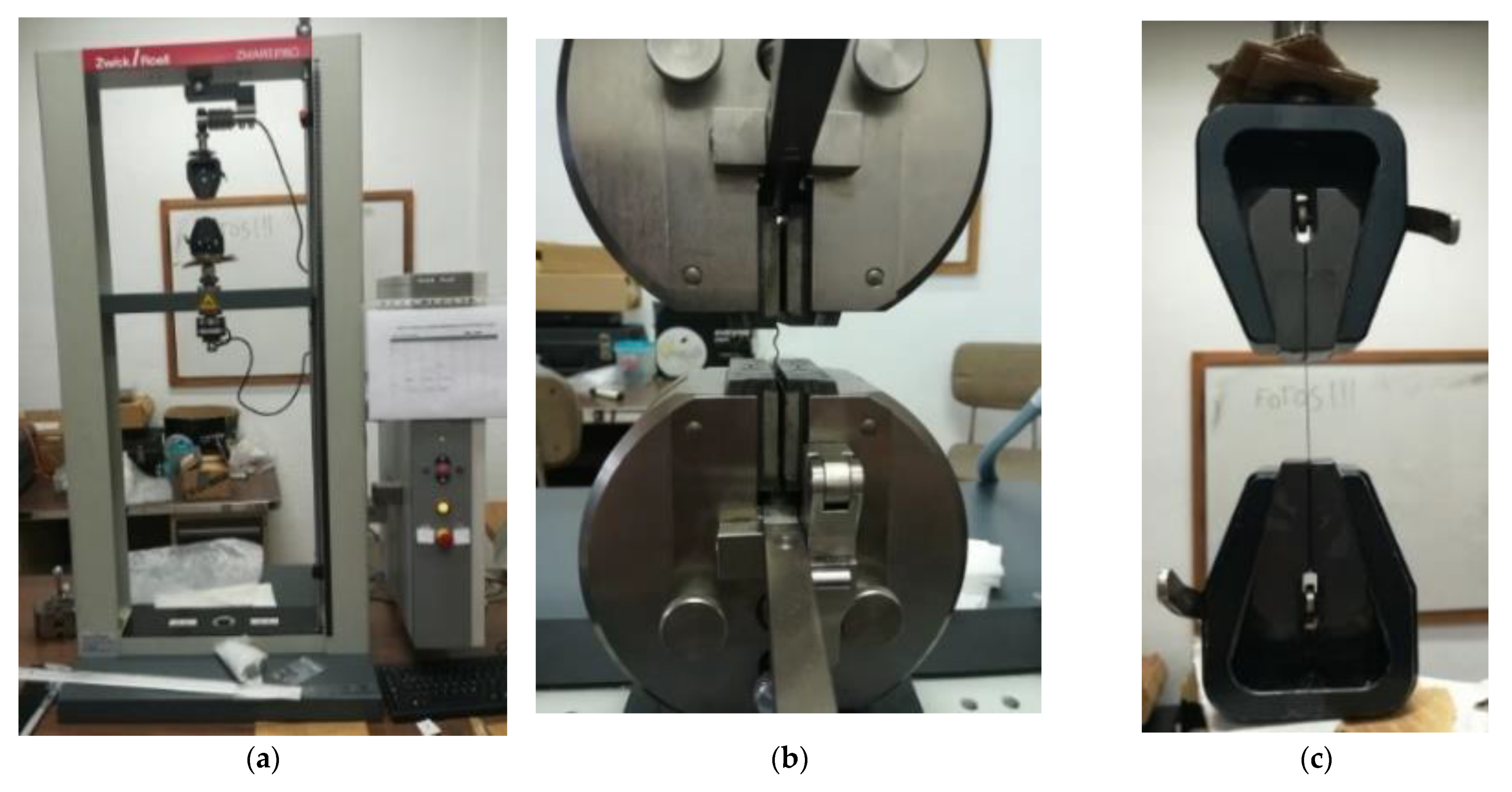
2.2. Analytical Methods
2.2.1. Supplementary Cementitious Materials
2.2.2. Fibers
3. Results
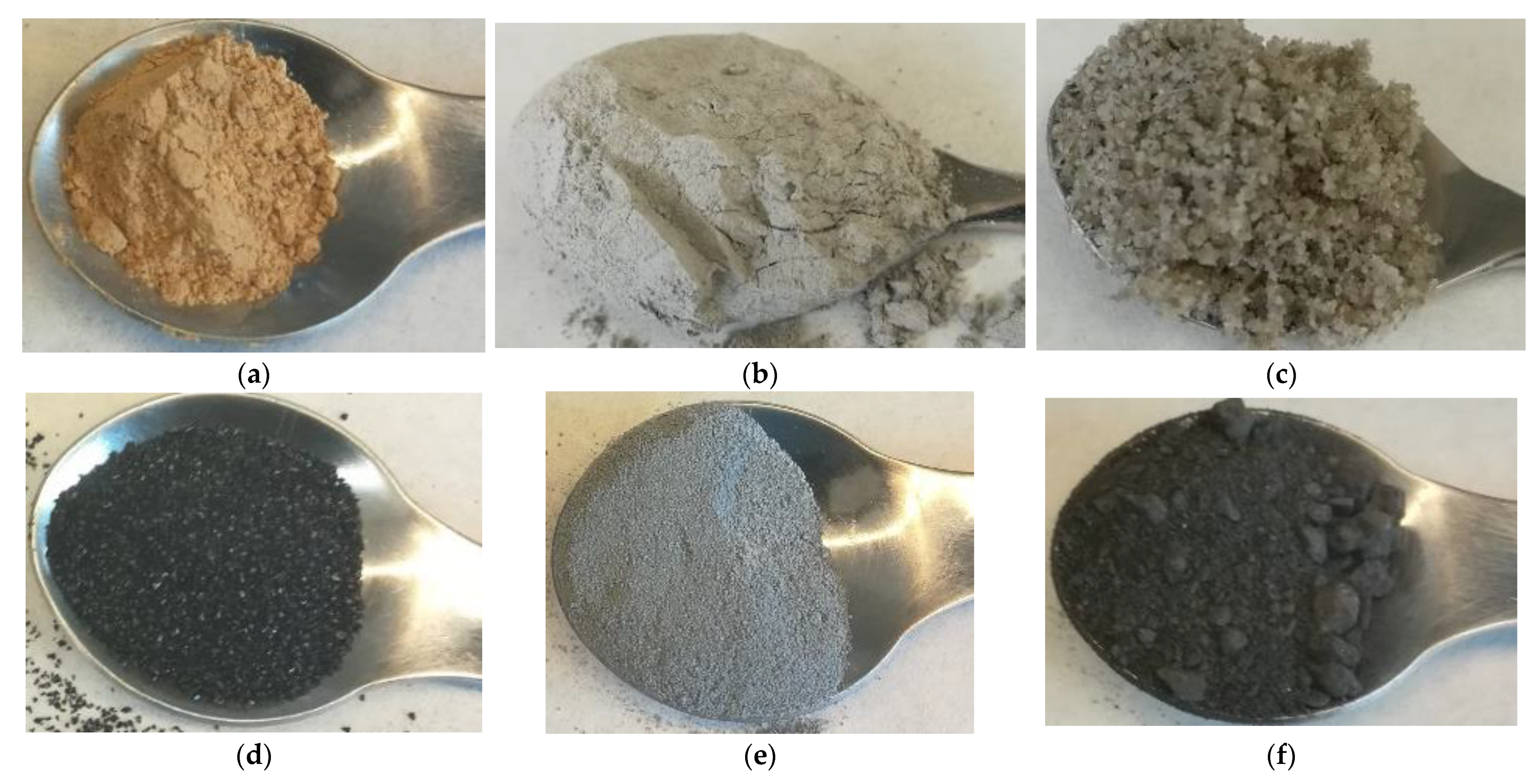
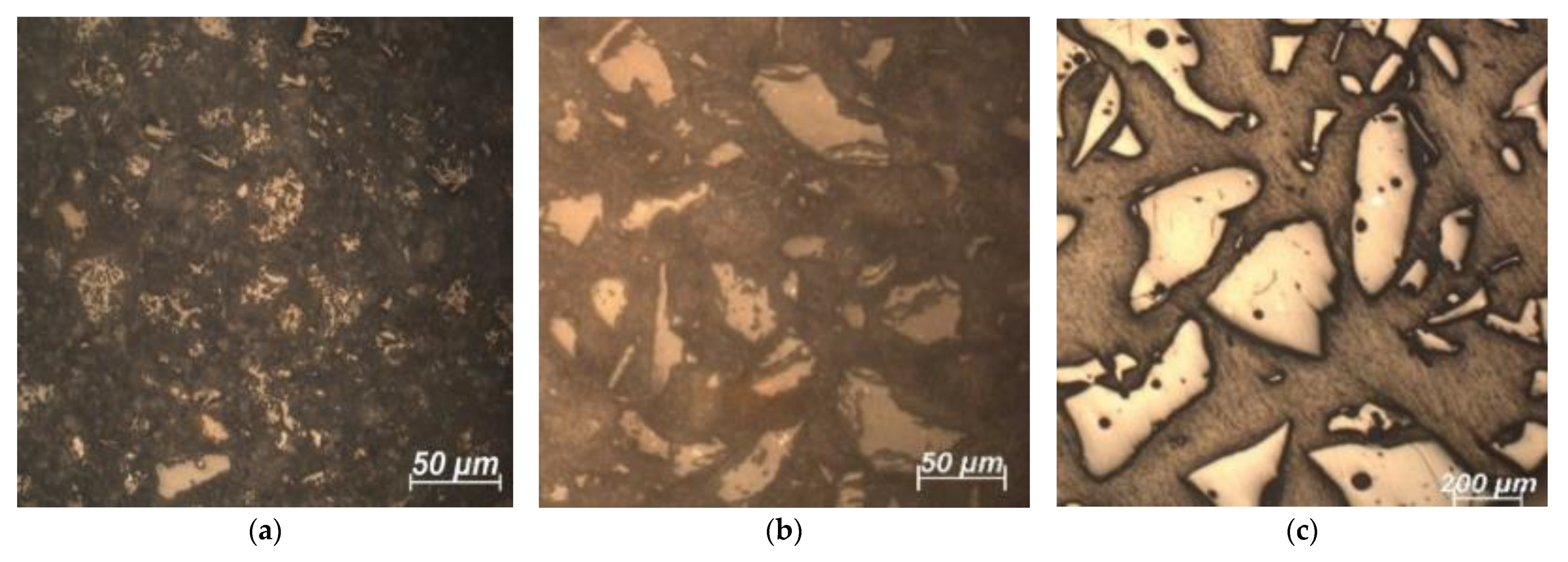
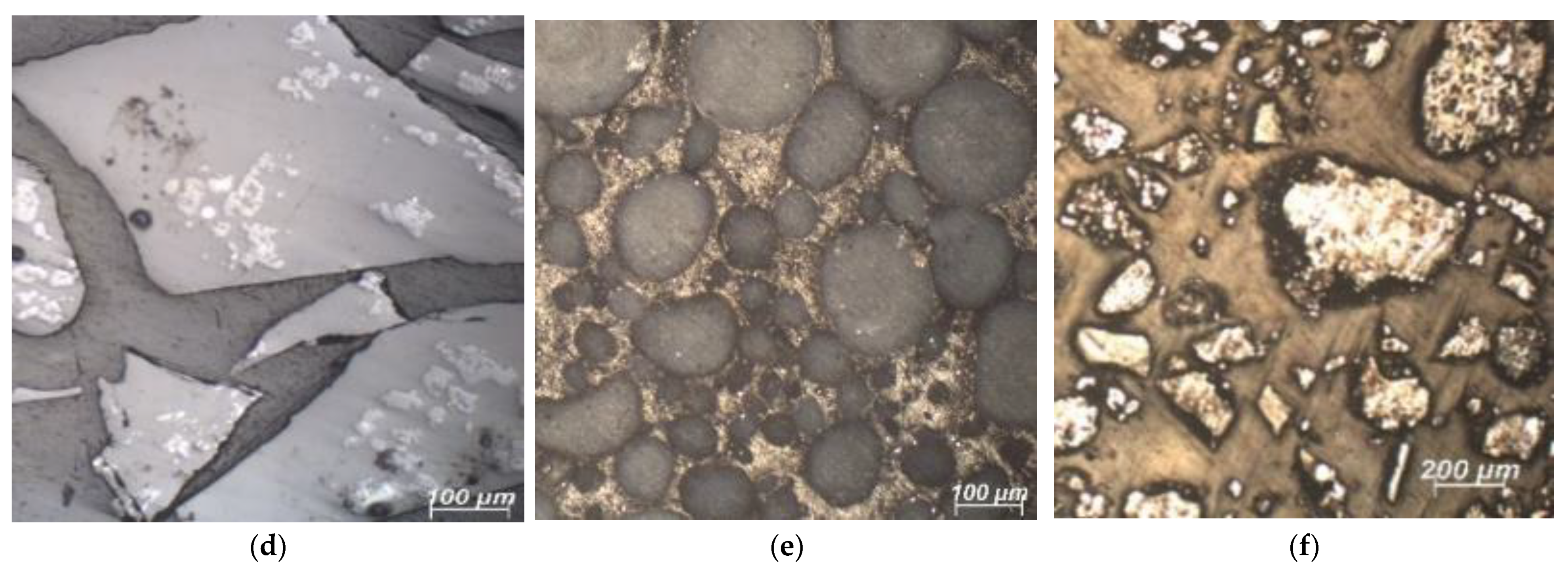
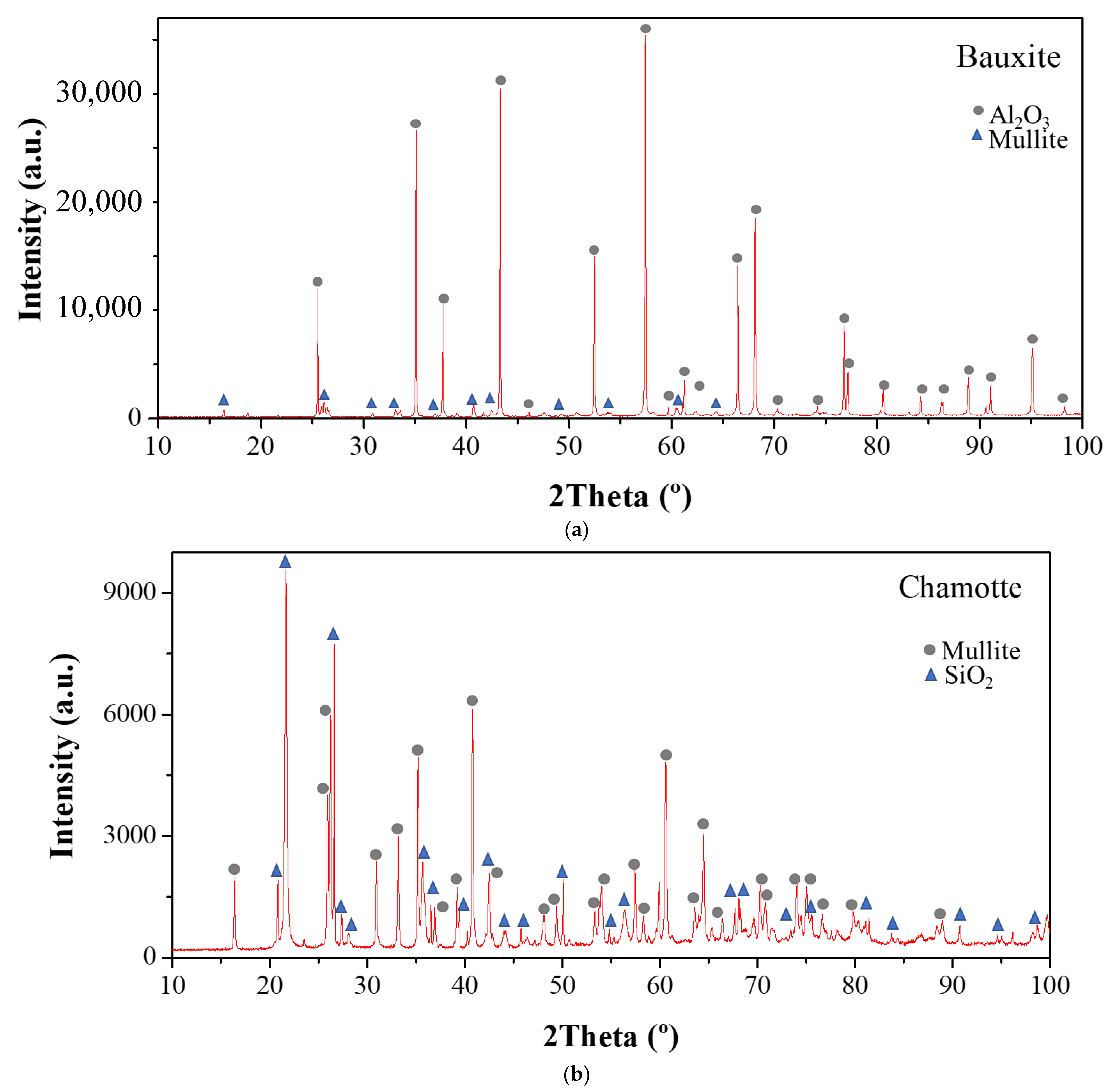
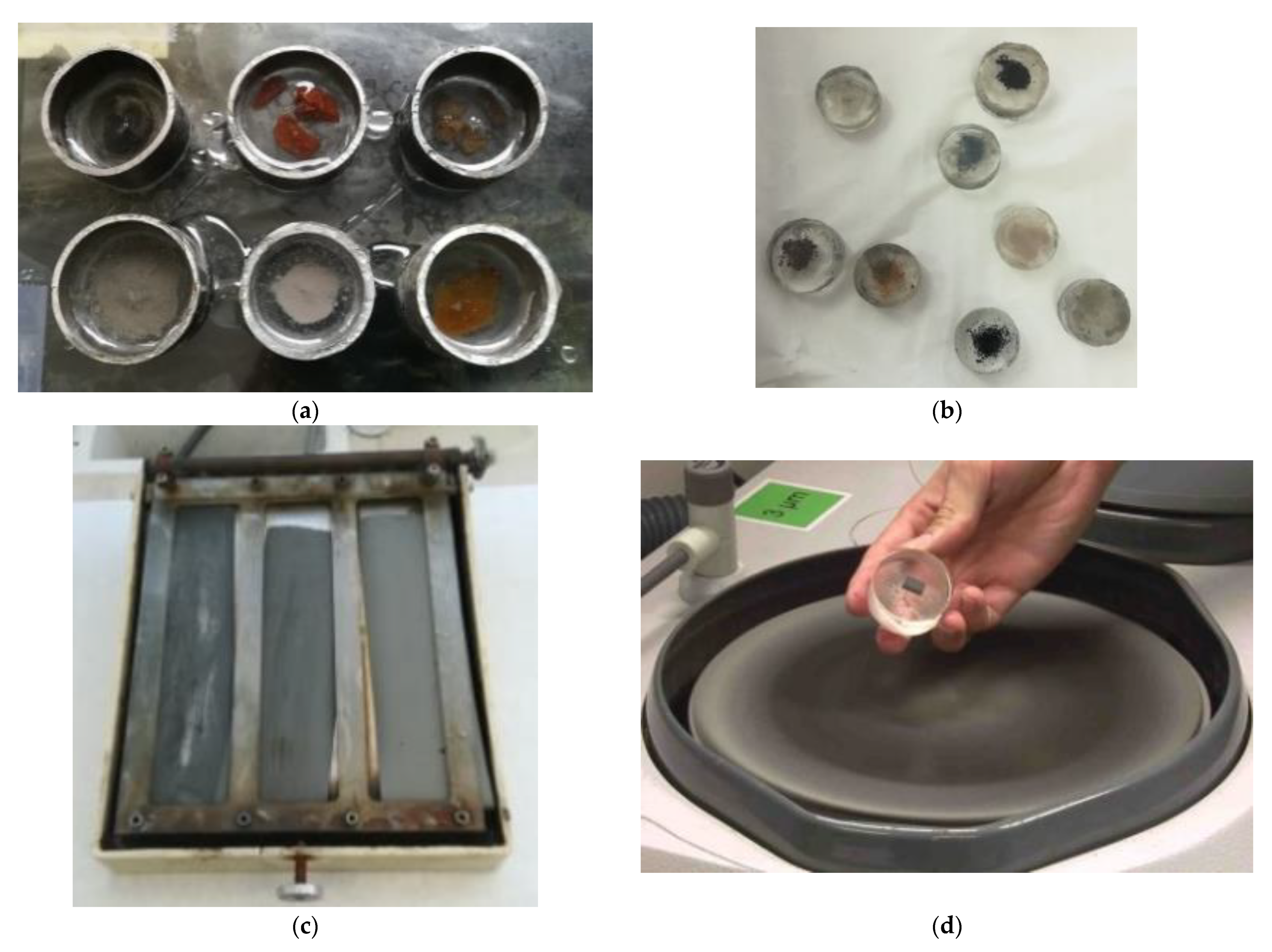
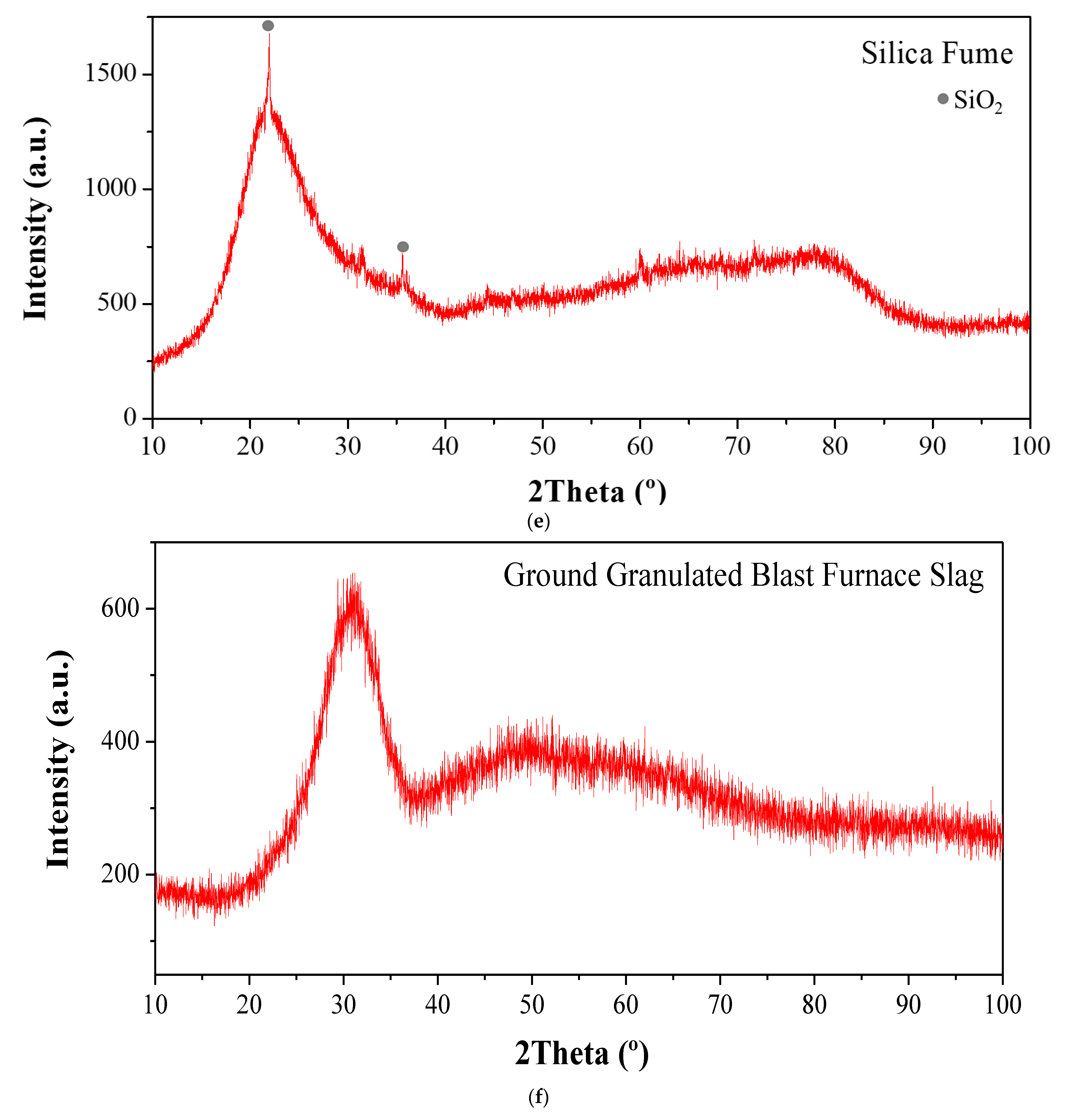
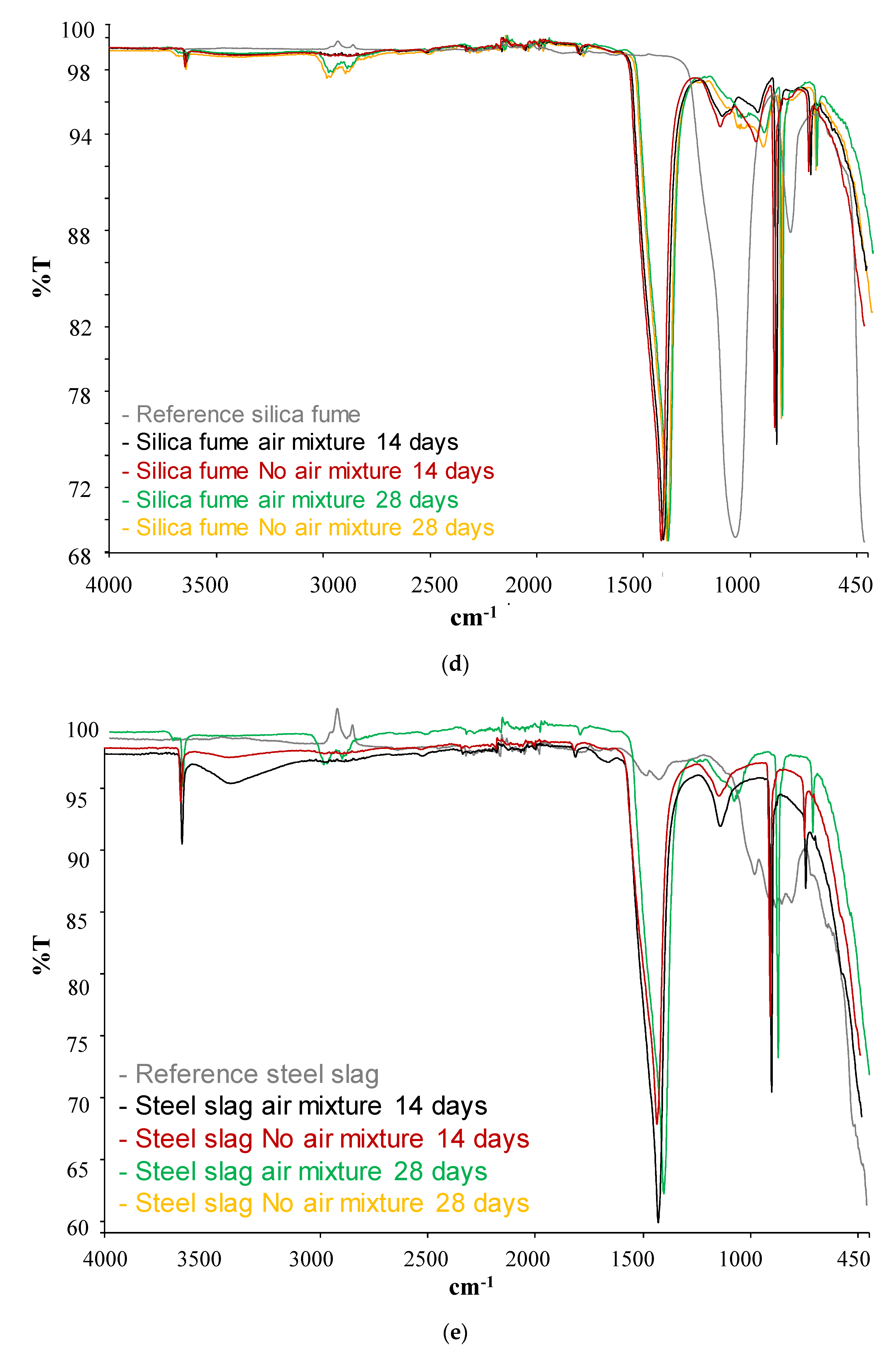
3.1. SCM
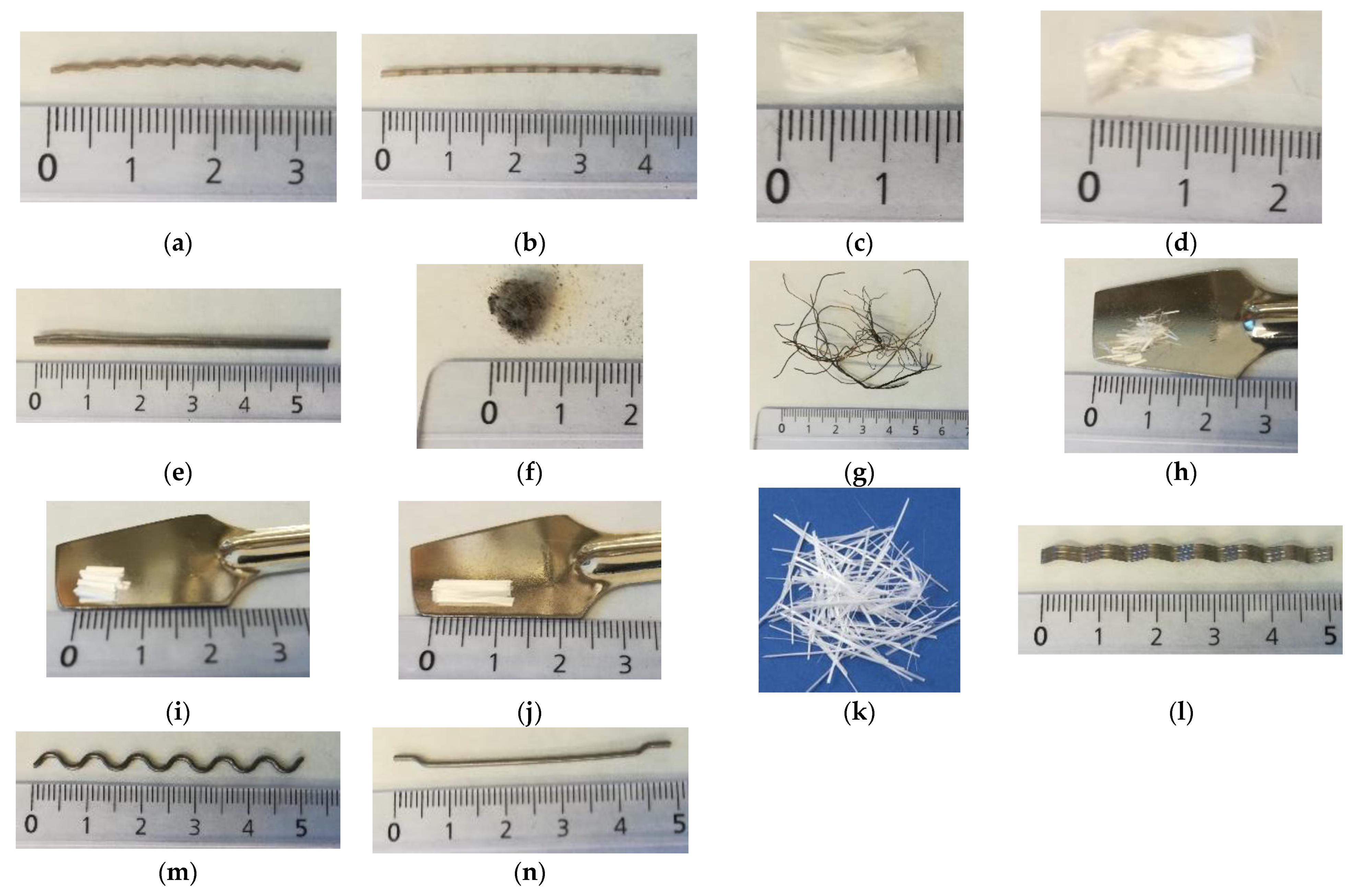
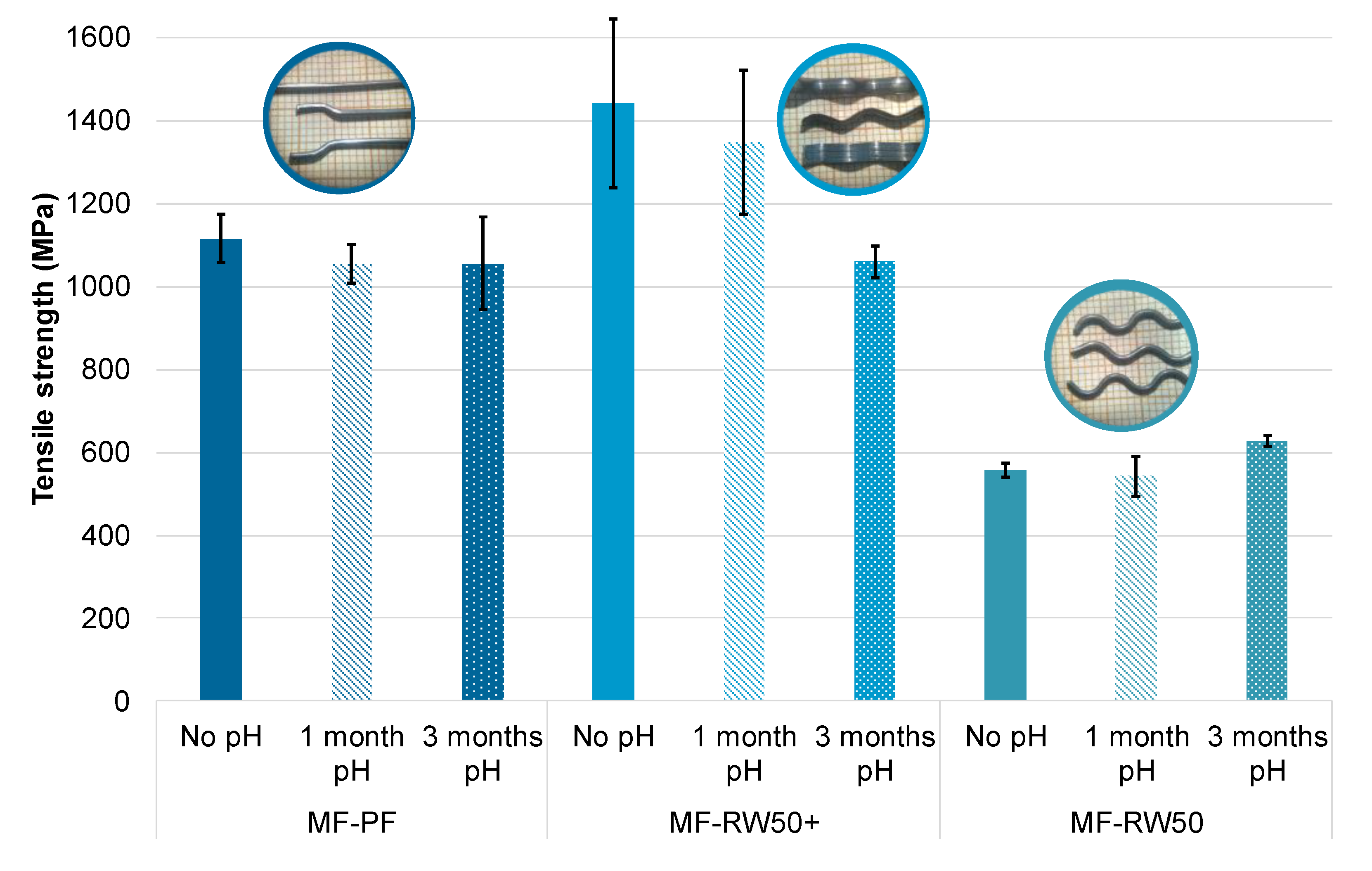
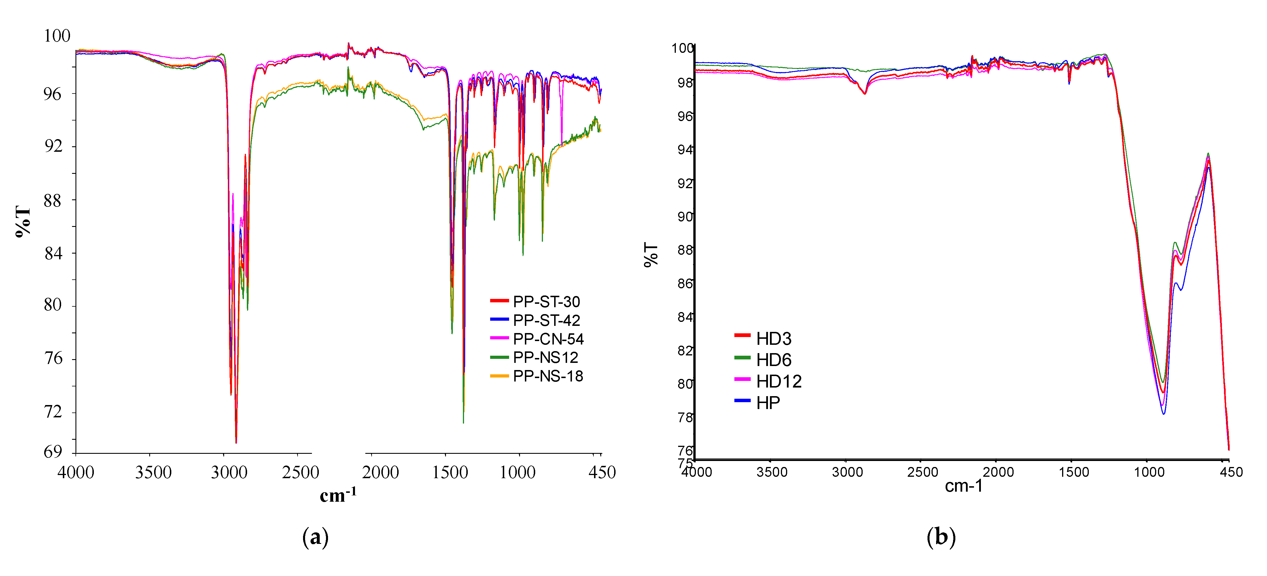
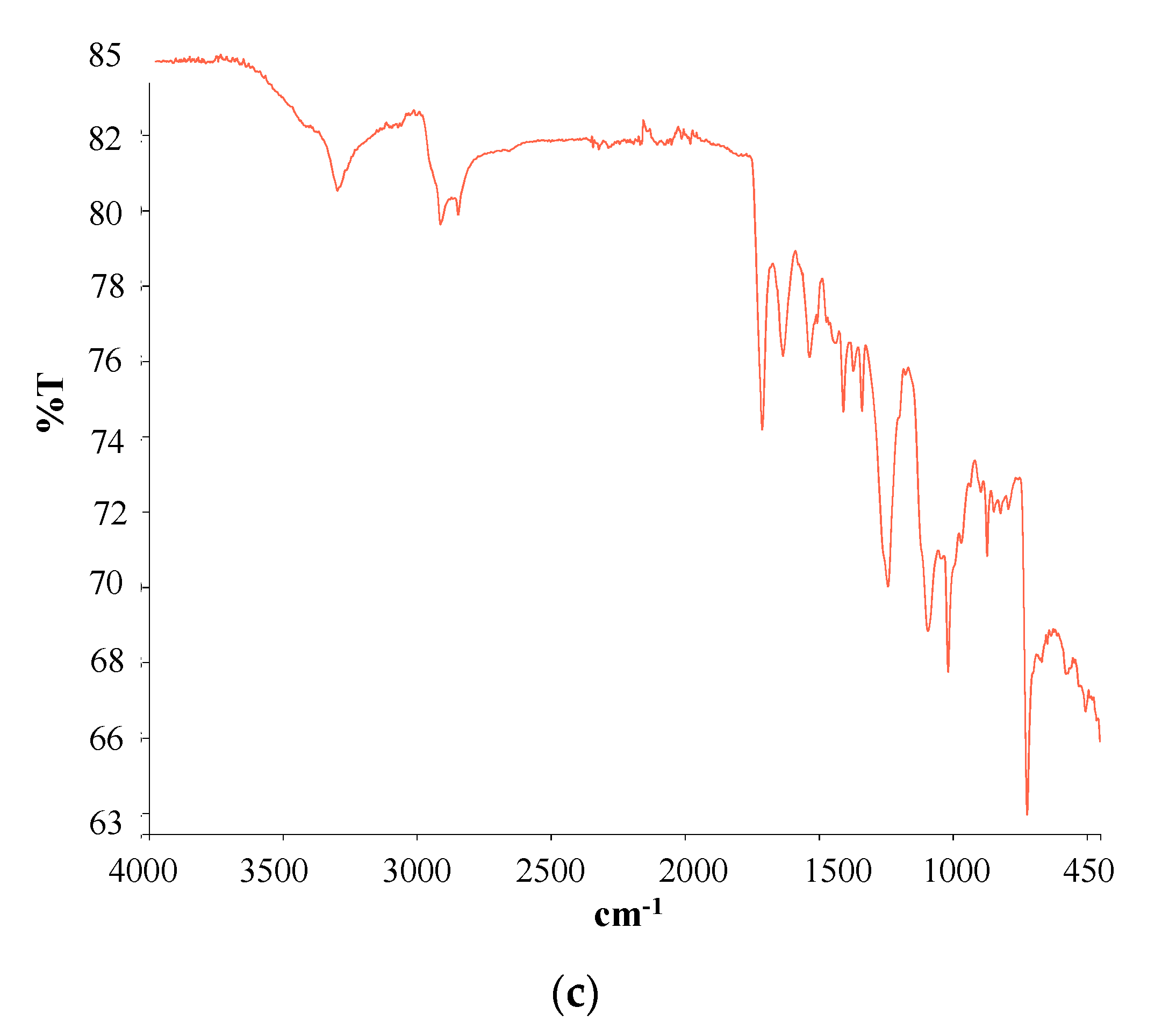
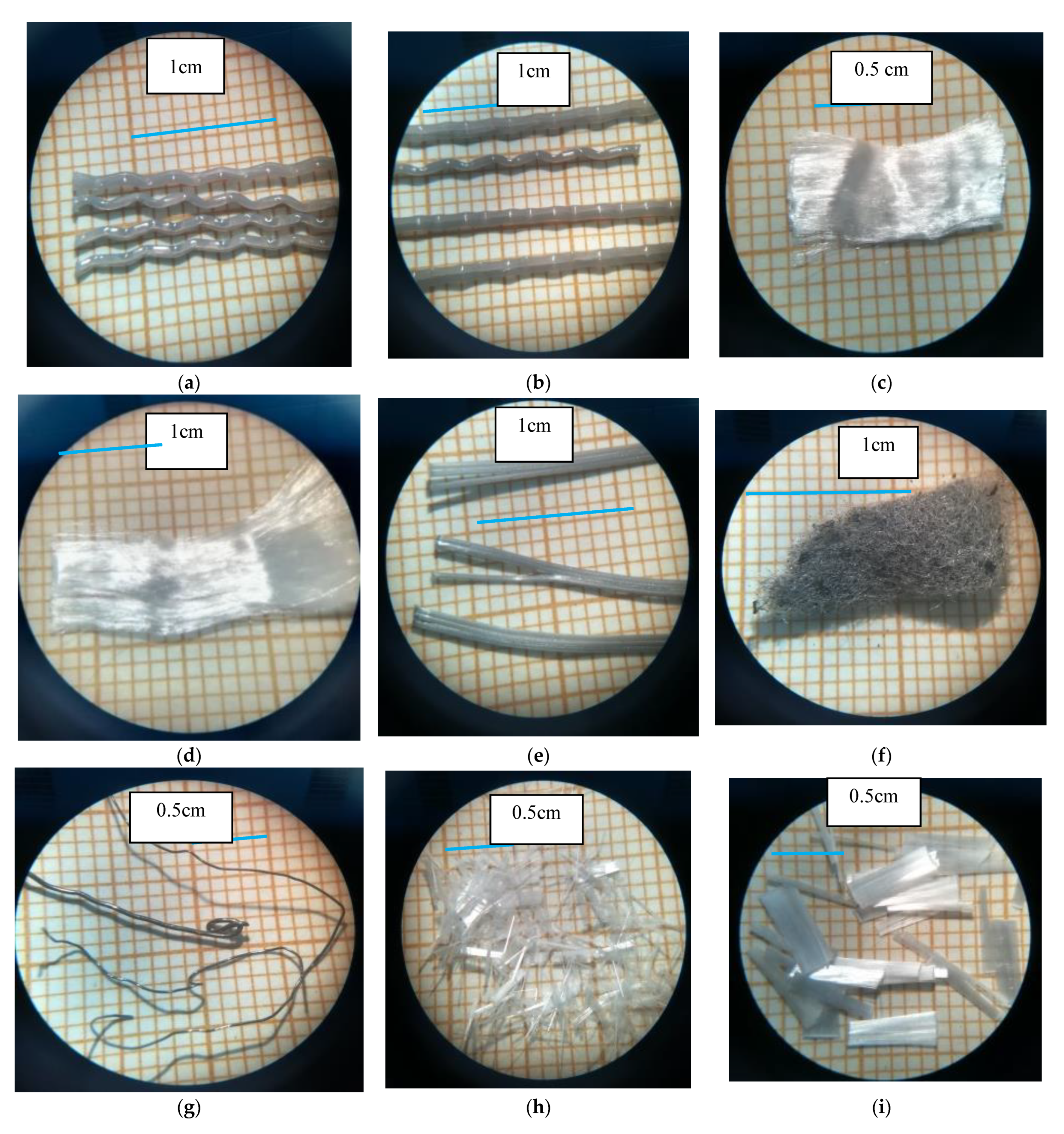
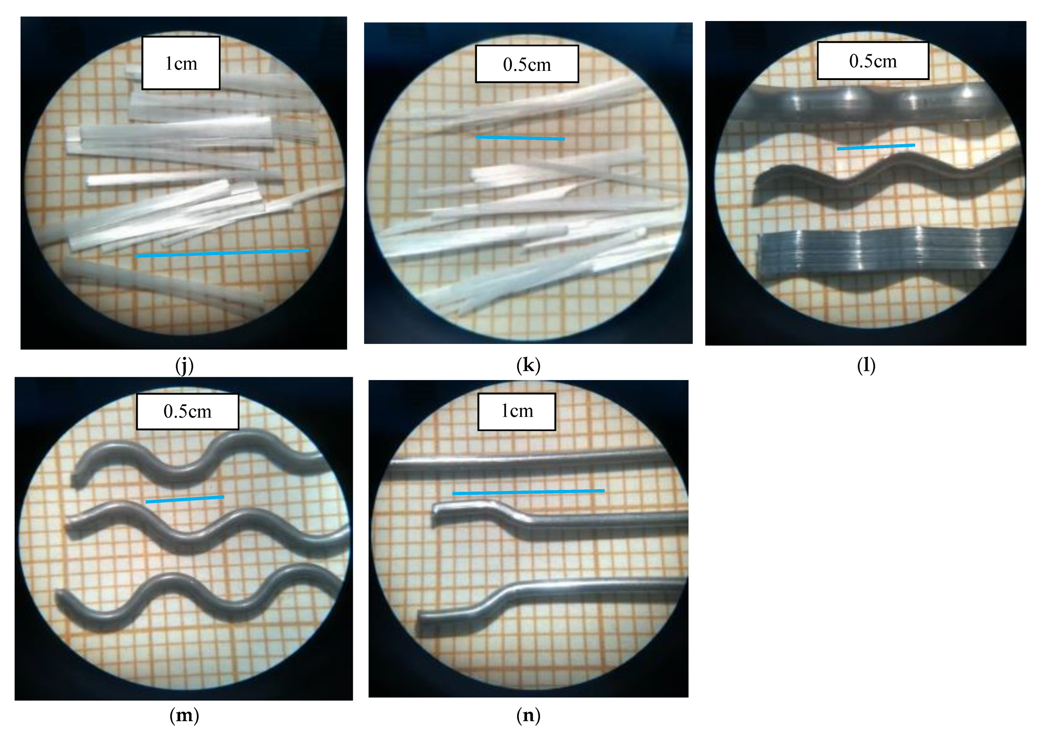
3.2. Fibers
4. Conclusions
Author Contributions
Funding
Institutional Review Board Statement
Informed Consent Statement
Data Availability Statement
Acknowledgments
Conflicts of Interest
References
- Martins, F.; Felgueiras, C.; Smitkova, M.; Caetano, N. Analysis of fossil fuel energy consumption and environmental impacts in european countries. Energies 2019, 12, 964. [Google Scholar] [CrossRef] [Green Version]
- Kabir, E.; Kumar, P.; Kumar, S.; Adelodun, A.A.; Kim, K.H. Solar energy: Potential and future prospects. Renew. Sustain. Energy Rev. 2018, 82, 894–900. [Google Scholar] [CrossRef]
- Bórawski, P.; Yashchenko, T.; Sviderskyi, A.; Dunn, J.W. Development of renewable energy market in the EU with particular regard to solar energy. Conf. Proc. Determ. Reg. Dev. 2019, 43–55. [Google Scholar] [CrossRef]
- Medrano, M.; Gil, A.; Martorell, I.; Potau, X.; Cabeza, L.F. State of the art on high-temperature thermal energy storage for power generation. Part 2-Case studies. Renew. Sustain. Energy Rev. 2010, 14, 56–72. [Google Scholar] [CrossRef]
- Gil, A.; Medrano, M.; Martorell, I.; Lázaro, A.; Dolado, P.; Zalba, B.; Cabeza, L.F. State of the art on high temperature thermal energy storage for power generation. Part 1-Concepts, materials and modellization. Renew. Sustain. Energy Rev. 2010, 14, 31–55. [Google Scholar] [CrossRef]
- Fernández, A.G.; Gomez-Vidal, J.; Oró, E.; Kruizenga, A.; Solé, A.; Cabeza, L.F. Mainstreaming commercial CSP systems: A technology review. Renew. Energy 2019, 140, 152–176. [Google Scholar] [CrossRef]
- González-Roubaud, E.; Pérez-Osorio, D.; Prieto, C. Review of commercial thermal energy storage in concentrated solar power plants: Steam vs. molten salts. Renew. Sustain. Energy Rev. 2017, 80, 133–148. [Google Scholar] [CrossRef]
- Khare, S.; Dell’Amico, M.; Knight, C.; McGarry, S. Selection of materials for high temperature sensible energy storage. Sol. Energy Mater. Sol. Cells 2013, 115, 114–122. [Google Scholar] [CrossRef]
- Laing, D.; Bahl, C.; Bauer, T.; Fiss, M.; Breidenbach, N.; Hempel, M. High-temperature solid-media thermal energy storage for solar thermal power plants. Proc. IEEE 2012, 100, 516–524. [Google Scholar] [CrossRef]
- John, E.E.; Hale, W.M. Effect of High Temperatures and Heating Rates on High Strength. Energy Sustain. 2010, 43956, 709–713. [Google Scholar]
- Lothenbach, B.; Scrivener, K.; Hooton, R.D. Supplementary cementitious materials. Cem. Concr. Res. 2011, 41, 1244–1256. [Google Scholar] [CrossRef]
- Snellings, R.; Mertens, G.; Elsen, J. Supplementary cementitious materials. Rev. Mineral. Geochem. 2012, 74, 211–278. [Google Scholar] [CrossRef]
- Juenger, M.C.G.; Snellings, R.; Bernal, S.A. Supplementary cementitious materials: New sources, characterization, and performance insights. Cem. Concr. Res. 2019, 122, 257–273. [Google Scholar] [CrossRef]
- CEN (European Committee for Standarization). EN-197. 1 Cement Composición, Especificaciones y Criterios de Conformidad de los Cementos Comunes; CEN (European Committee for Standarization): Brussels, Belgium.
- Snellings, R. Assessing, Understanding and Unlocking Supplementary Cementitious Materials. RILEM Tech. Lett. 2016, 1, 50. [Google Scholar] [CrossRef] [Green Version]
- John, E.; Hale, M.; Selvam, P. Concrete as a thermal energy storage medium for thermocline solar energy storage systems. Sol. Energy 2013, 96, 194–204. [Google Scholar] [CrossRef]
- Pan, J.; Zou, R.; Jin, F. Experimental study on specific heat of concrete at high temperatures and its influence on thermal energy storage. Energies 2017, 10, 33. [Google Scholar] [CrossRef] [Green Version]
- Wu, C.; Pan, J.; Zhong, W.; Jin, F. Testing of high thermal cycling stability of low strength concrete as a thermal energy storage material. Appl. Sci. 2016, 6, 271. [Google Scholar] [CrossRef] [Green Version]
- Alonso, M.C.; Vera-Agullo, J.; Guerreiro, L.; Flor-Laguna, V.; Sanchez, M.; Collares-Pereira, M. Calcium aluminate based cement for concrete to be used as thermal energy storage in solar thermal electricity plants. Cem. Concr. Res. 2016, 82, 74–86. [Google Scholar] [CrossRef]
- El-Sharkawy, H.; El Bably, M.; Omar, I.; Adel, R.; Gendy, R.; Minass, A.; Fathy, A.; Abou-Zeid, M.N.; Fahmy, E. Thermal storage concrete. In Proceedings of the 2015 CSCE Annual Conference, Regina, SK, Canada, 27–30 May 2015; pp. 1–10. [Google Scholar]
- Chengzhou, G.; Jiaoqun, Z.; Weibing, Z.; Wen, C. Fabrication and thermal properties of a new heat storage concrete material. J. Wuhan Univ. Technol. Sci. Ed. 2010, 25, 628–630. [Google Scholar] [CrossRef]
- Gil, A.; Calvet, N.; Ortega, I.; Risueño, E.; Faik, A.; Rodríguez-aseguinolaza, J. Characterization of a by-product from steel industry applied to thermal energy storage in Concentrated Solar Power. Proc. Eurotherm Semin. 2014, 99, 1–9. [Google Scholar]
- Ortega-Fernández, I.; Calvet, N.; Gil, A.; Rodríguez-Aseguinolaza, J.; Faik, A.; D’Aguanno, B. Thermophysical characterization of a by-product from the steel industry to be used as a sustainable and low-cost thermal energy storage material. Energy 2015, 89, 601–609. [Google Scholar] [CrossRef]
- Miró, L.; Navarro, M.E.; Suresh, P.; Gil, A.; Fernández, A.I.; Cabeza, L.F. Experimental characterization of a solid industrial by-product as material for high temperature sensible thermal energy storage (TES). Appl. Energy 2014, 113, 1261–1268. [Google Scholar] [CrossRef]
- Gutierrez, A.; Miró, L.; Gil, A.; Rodríguez-Aseguinolaza, J.; Barreneche, C.; Calvet, N.; Py, X.; Fernández, A.I.; Grágeda, M.; Ushak, S.; et al. Advances in the valorization of waste and by-product materials as thermal energy storage (TES) materials. Renew. Sustain. Energy Rev. 2016, 59, 763–783. [Google Scholar] [CrossRef] [Green Version]
- Cánovas, M.F. Hormigones con fibras: Tecnología y propiedades generales. Hormigón y Acero 2003, 54, 167–176. [Google Scholar]
- ACI. ACI Committee 544 1R, Report on Fiber Reinforced Concretes; ACI: Indianapolis, IN, USA, 1996. [Google Scholar]
- Romualdi, J.P.; Batson, G.B. Mechanics of Crack Arrest in Concrete. J. Eng. Mech. ASCE 1963, 89, 147–168. [Google Scholar]
- Biryukovich, K.L.; Yu, D.L. Glass Fiber Reinforced Cement. Civ. Eng. Res. Assoc. 1965, 41. [Google Scholar]
- Ma, Q.; Guo, R.; Zhao, Z.; Lin, Z.; He, K. Mechanical properties of concrete at high temperature-A review. Constr. Build. Mater. 2015, 93, 371–383. [Google Scholar] [CrossRef]
- Ozger, O.B.; Girardi, F.; Giannuzzi, G.M.; Salomoni, V.A.; Majorana, C.E.; Fambri, L.; Baldassino, N.; Di Maggio, R. Effect of nylon fibers on mechanical and thermal properties of hardened concrete for energy storage systems. Mater. Des. 2013, 51, 989–997. [Google Scholar] [CrossRef]
- Girardi, F.; Giannuzzi, G.M.; Mazzei, D.; Salomoni, V.; Majorana, C.; Di Maggio, R. Recycled additions for improving the thermal conductivity of concrete in preparing energy storage systems. Constr. Build. Mater. 2017, 135, 565–579. [Google Scholar] [CrossRef]
- Ríos, J.D.; Cifuentes, H.; Leiva, C.; García, C.; Alba, M.D. Behavior of high-strength polypropylene fiber-reinforced self-compacting concrete exposed to high temperatures. J. Mater. Civ. Eng. 2018, 30, 1–13. [Google Scholar] [CrossRef] [Green Version]
- Adeyanju, A.A.; Manohar, K. Effects of Steel Fibers and Iron Filings on Thermal and Mechanical Properties of Concrete for Energy Storage Application. J. Miner. Mater. Charact. Eng. 2011, 10, 1429–1448. [Google Scholar] [CrossRef]
- Adeyanju, A.A.; Manohar, K. Effects of steel fibers on properties of concrete for energy storage application. J. Eng. Appl. Sci. 2011, 6, 336–345. [Google Scholar] [CrossRef]
- John, E.E.; Hale, W.M.; Brown, B. Development and Performance Evaluation of High Temperature. In Proceedings of the ASME 2011 International Mechanical Engineering Congress and Exposition, Denver, CO, USA, 11–17 November 2011; 2011; pp. 1–7. [Google Scholar] [CrossRef]
- Ghafari, E.; Feys, D.; Khayat, K. Feasibility of using natural SCMs in concrete for infrastructure applications. Constr. Build. Mater. 2016, 127, 724–732. [Google Scholar] [CrossRef]
- Thomas, M. The effect of supplementary cementing materials on alkali-silica reaction: A review. Cem. Concr. Res. 2011, 41, 1224–1231. [Google Scholar] [CrossRef]
- European Center for Standarization. EN-12698-2. Chemical Analysis of Nitride Bonded Silicon Carbide Refractories; Part 2. XRD methods; European Center for Standarization: Brussels, Belgium, 2007; pp. 1–18. [Google Scholar]
- AENOR. UNE 53934:2016. Plásticos. Análisis Elemental en Materiales Poliméricos por el Método de Fluorescencia por Rayos X; AENOR: Madrid, Spain, 2016. [Google Scholar]
- Wang, S.; Peng, X.; Tang, L.; Zeng, L.; Lan, C. Influence of inorganic admixtures on the 11 Å-tobermorite formation prepared from steel slags: XRD and FTIR analysis. Constr. Build. Mater. 2014, 60, 42–47. [Google Scholar] [CrossRef]
- AENOR. UNE 40-248-75. Método para el Ensayo de Tracción. Dinamometria de Hace Planos de Fibras de lana; AENOR: Madrid, Spain, 1975; Volume 75. [Google Scholar]
- ASTM (D638). American Society for Testing and Materials. Standard Test Method for Tensile Properties of Plastics (D 638-02a)—SCAN VERSION; ASTM: West Conshohocken, PA, USA, 2003; Volume 8, pp. 46–58. [Google Scholar] [CrossRef]
- Micelli, F.; Aiello, M.A. Residual tensile strength of dry and impregnated reinforcement fibers after exposure to alkaline environments. Compos. Part B Eng. 2019, 159, 490–501. [Google Scholar] [CrossRef]
- Stepanek, P.; Janus, O.; Girgle, F.; Bodnarova, L.; Kostiha, V.; Rozsypalova, I. Long term strength of internal GFRP reinforcement by alkaline, temperature and cyclic loading. Procedia Struct. Integr. 2018, 11, 12–19. [Google Scholar] [CrossRef]
- Barbeş, L.; Rădulescu, C.; Stihi, C. ATR-FTIR spectrometry characterization of polymeric materials. Rom. Rep. Phys. 2014, 66, 765–777. [Google Scholar]
- Morales, A.; Pérez, G.F. Caracterización por espectroscopía en el infrarrojo de óxidos de silicio depositados en ambiente de N2O. Superf. Y Vacío 2003, 16, 16–18. [Google Scholar]
- Cecen, V.; Seki, Y.; Sarikanat, M.; Tavman, I.H. FTIR and SEM analysis of polyester- and epoxy-based composites manufactured by VARTM process. J. Appl. Polym. Sci. 2008, 108, 2163–2170. [Google Scholar] [CrossRef]


| Type of SCM | % SCM | kg/m3 SCM | kg/m3 Cement | Cement Type | Particle Size Distribution | Chemical Composition | XRD | TG | Maximum Temperature (°C) | Reference |
|---|---|---|---|---|---|---|---|---|---|---|
| Fly ash | 40 | 214 | 320 | CAC | - | - | - | - | [16] | |
| 50 | 265 | 265 | - | - | - | - | ||||
| 60 | 320 | 214 | - | - | - | - | ||||
| 70 | 374 | 160 | - | - | - | - | 600 | |||
| 50 | 193 | 193 | OPC | - | - | - | - | |||
| 70 | 249 | 107 | - | - | - | - | ||||
| 43 | 160 | 210 | OPC | - | - | - | - | 600 | [17,18] | |
| Ground granulated blast furnace slag | 30 | CAC | yes | yes | yes | yes | 550 | [19] | ||
| Silica fume | 10 | 66 | 596 | OPC | - | - | - | - | 600 | [10] |
| - | - | - | - | - | 600 | [20] | ||||
| Fly ash Silica fume | 56 11 | 267 54 | 214 | CAC | - | - | - | - | 600 | [16] |
| 47 5 | 160 18 | 178 | OPC | - | - | - | - | 600 | ||
| Silica micro powder Aluminum powder | - | - | - | CAC | - | yes | - | - | 1100 | [21] |
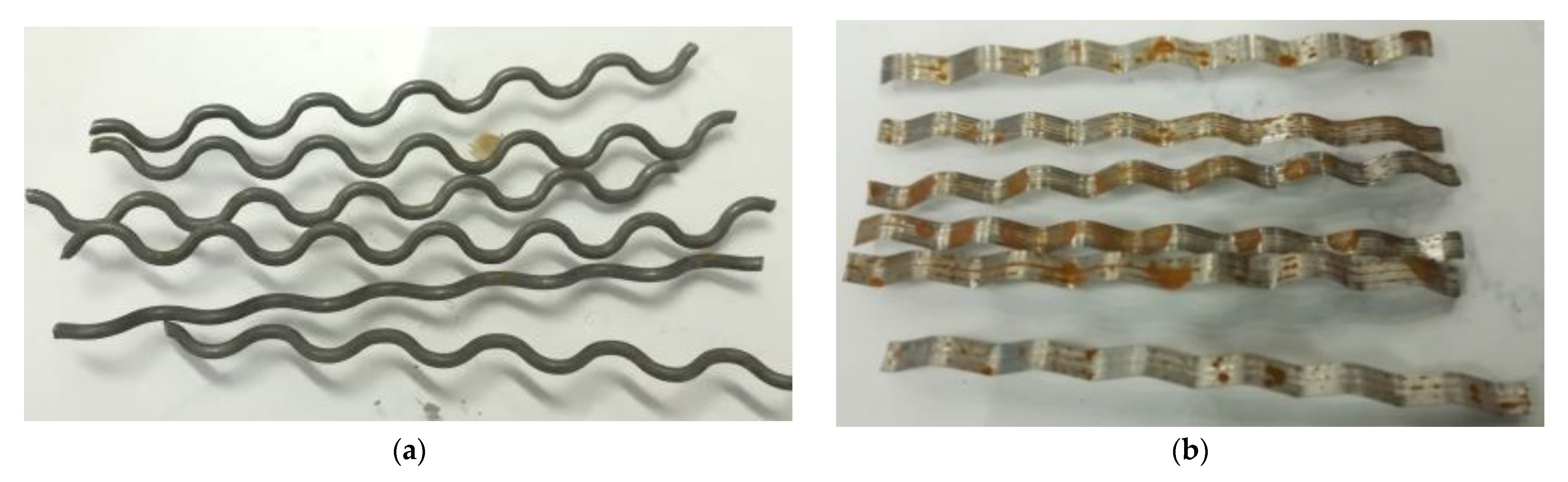
| Type of Fibers | Diameter | Length (mm) | Tensile Strength of the Fiber (MPa) | Melting Temperature (°C) | Density | Weight in Concrete (kg/m3) | Reference |
|---|---|---|---|---|---|---|---|
| Polypropylene fibers | 33 µm | 6 | 450 | - | - | - | [33] |
| 24 | - | - | - | ||||
| Nylon polyamide PA66 fibers | 38–41 µm | 8 ± 3 | 286 ± 38 | 285 | 13–15 dtex | - | [31,32] |
| Metal powders | 12 µm | - | - | - | - | - | [32] |
| Steel fibers | 530 µm | 11 ± 1 | 400 ± 38 | 1435 | - | - | |
| Recycled metal shavings | 0.1–0.2 mm2 | 10–30 | - | - | - | - | |
| Steel fiber | 0.9 mm | 50 | - | - | -- | 0.2 | [34,35] |
| 25 | |||||||
| 10 | |||||||
| PP fibers | 18 µm | 12.7 | - | - | - | - | [16] |
| Steel fibers | - | - | - | - | - | 2 | [10,16,36] |
| Product | Bauxite | Chamotte | Ground Granulated Blast Furnace Slag | Iron Silicate | Silica Fume | Steel Slag |
|---|---|---|---|---|---|---|
| Al2O3 | 89.94 | 40.70 | 9–13 | 6–12 | 0.15 | 13.50 |
| SiO2 | 5.36 | 55.24 | 34–38 | 22–30 | 97 | 19.10 |
| Fe2O3 | 1.14 | 0.32 | - | 25–35 | 0.03 | 27.00 |
| TiO2 | 3.02 | 1.09 | <1 | - | - | - |
| CaO | 0.02 | <0.10 | 40–44 | 5–8 | 0.20 | 27.90 |
| MgO | 0.02 | <0.10 | 6–9 | - | 0.30 | 2.50 |
| Na2O | 0.02 | 0.02 | - | - | 0.05 | - |
| K2O | 0.03 | 1.47 | - | - | 0.80 | - |
| CuO | - | - | - | 0.3–0.9 | - | - |
| ZnO | - | - | - | 5–9 | - | - |
| Cr2O2 | - | - | - | - | - | 2.50 |
| MnO | - | - | - | - | - | 5.4 |
| apparent density (g/cm3) | 3.15 | 2.44 | 1.1 | 3.3 | 2.25 | 3.57 |
| apparent porosity (%) | 12 | 6 | - | - | - | - |
| Characteristics | Fiber Type | ||||||||
|---|---|---|---|---|---|---|---|---|---|
| Polypropylene Fibers | Glass Fibers | Metal | |||||||
| PP- ST30 | PP- ST42 | PP- NS12 | PP- NS18 | PP- CN54 | GF-HD12 | GF- HP | RW 50 | RW 50+ | |
| Aspect */shape | NF | NF | F | F | F | F | F | NF | NF |
| Color | Grey | Grey | White | White | Grey | White | White | Grey | Grey |
| Length fiber (mm) | 30 | 42 | 12 | 12 | 54 ± 5% | 12 | 18 | 50 ± 3 | 50 ± 3 |
| Equivalent diameter (mm) | 0.80 | 0.80 | 0.032 ± 0.002 | 0.032 ± 0.002 | 0.32 ± 5% | 0.014 | 0.014 | 1.0 ± 0.05 | 0.6–0.9 |
| Density (g/cm3) | 1.00 | 1.00 | 0.91 | 0.91 | 0.91 ± 0.02 | 2.68 | 2.68 | 7.80 | 7.80 |
| Water absorption (%) | ≤0.1 | ≤0.01 | - | - | ≤0.01 | - | - | - | - |
| Melting point (°C) | 155–165 | 155–165 | 165 ± 5 | 165 ± 5 | 165 ± 5 | 860 | 860 | - | - |
| Alkali, salt, and acid resistance | High | High | High | High | High | High | High | - | - |
| Tensile strength (N/mm2) | 450 | 450 | - | - | ≥500 | 1.700 | 1.700 | ≥1000 | 850 |
| Elastic modulus (N/mm2) | 3900 | 3900 | 400–500 | 400–500 | ≥5000 | 72,000 | 72,000 | - | - |
| Elongation at break (ISO 527) (%) | - | - | - | - | ≤20 | - | - | - | - |
| SCM | Particle Size |
|---|---|
| Bauxite | 11 and 31 µm |
| Chamotte | 17 and 55 µm |
| Ground granulated blast furnace slag | 50 and 420 µm |
| Iron silicate | 75 and 332 µm |
| Silica fume | 39 and 287 µm |
| Steel slag | 80 and 390 µm |
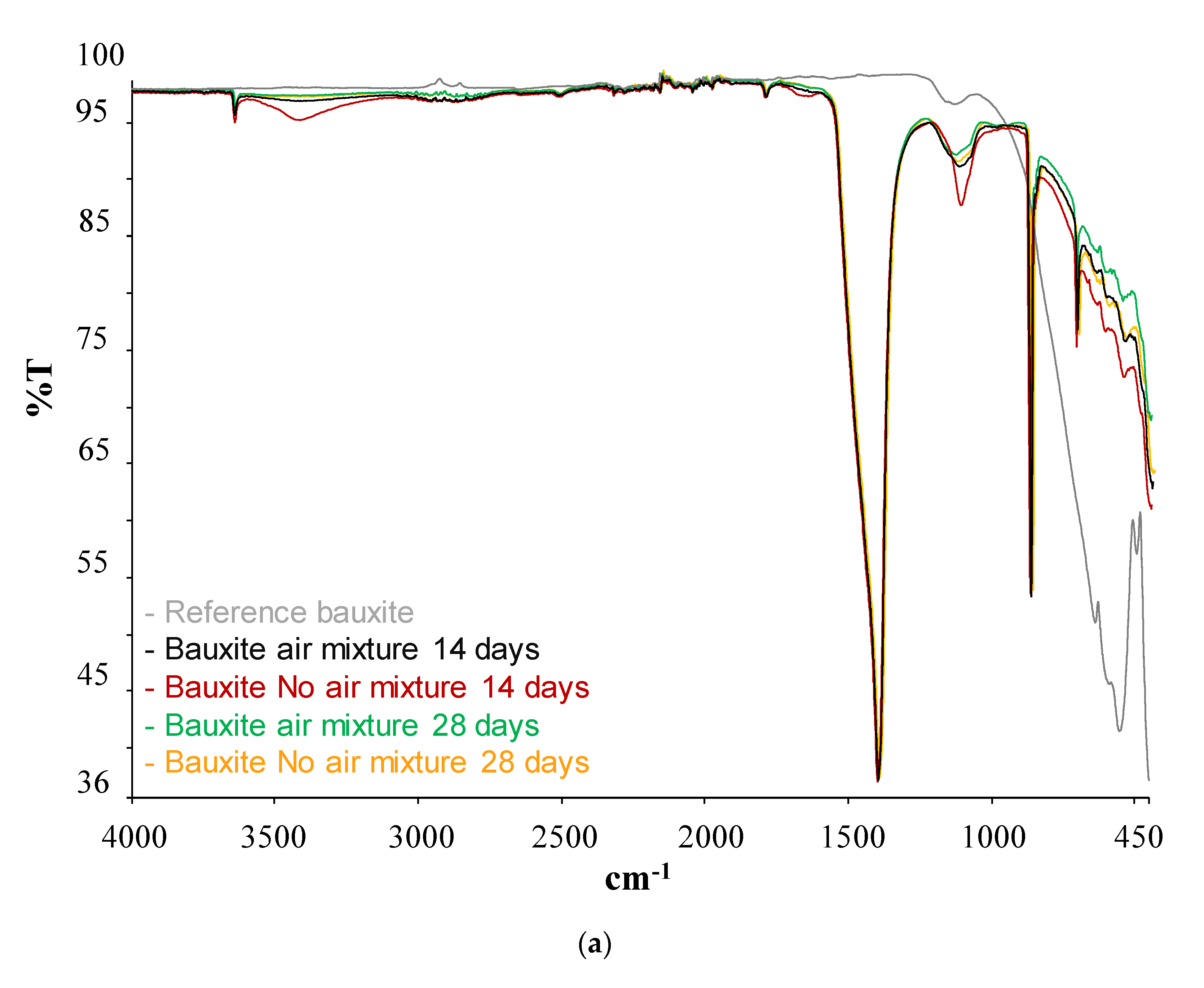
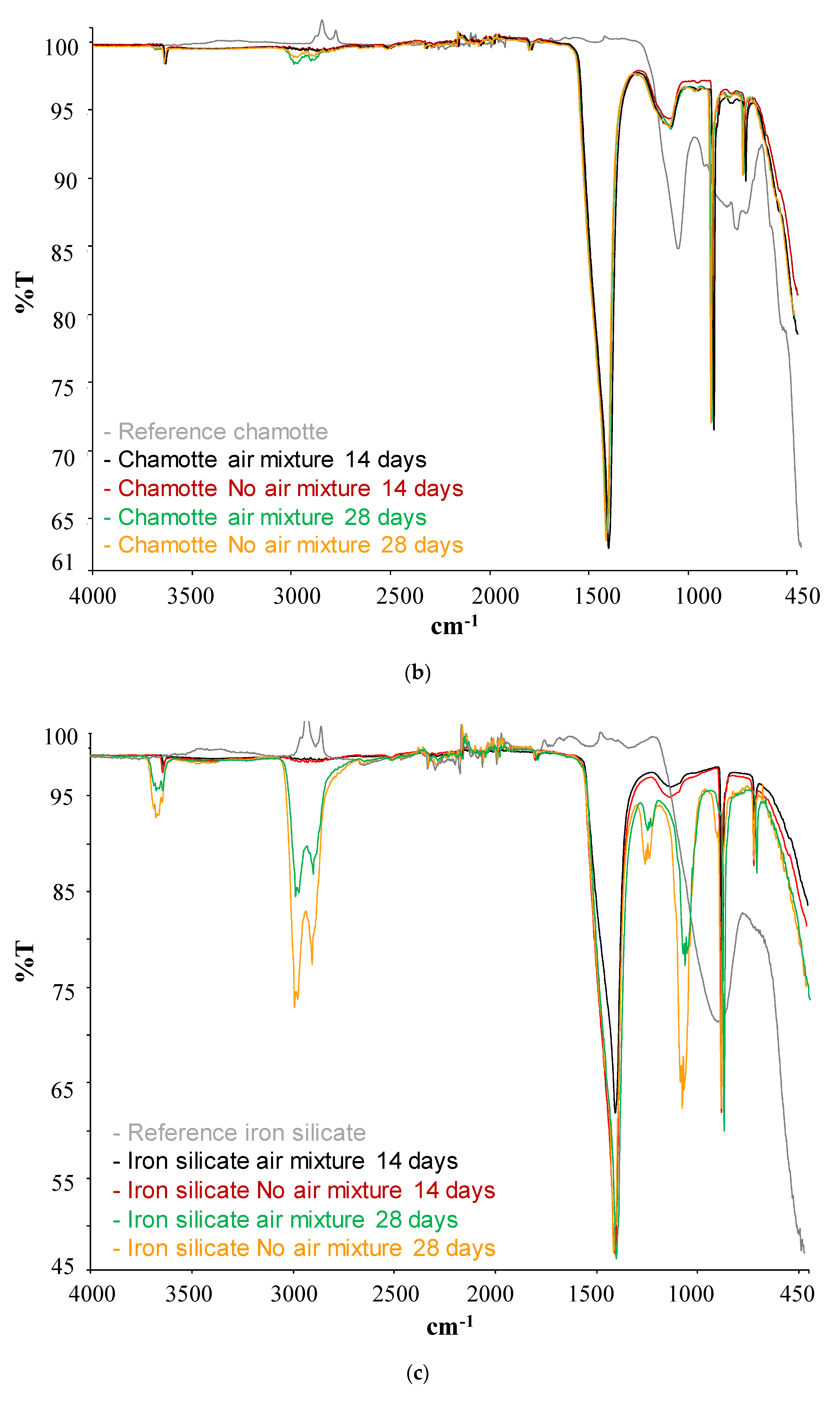
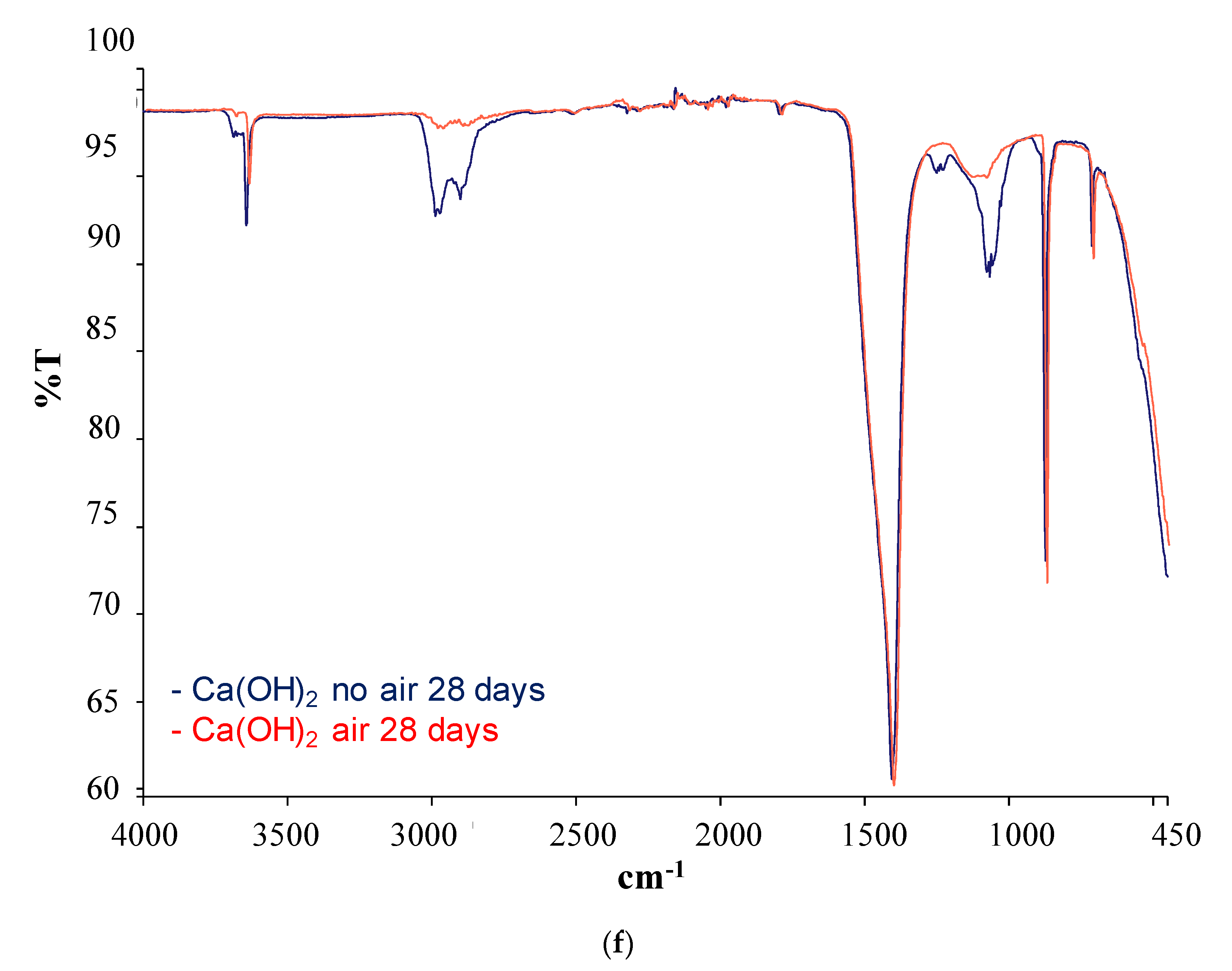
| SCM | Band (cm−1) | Phases | |
|---|---|---|---|
| Silica Fume | Before pozzolanic test | 1060 | Si-O (stretching) |
| 805 | Si-O (bending) | ||
| After pozzolanic test | 3600 | Ca(OH)2 | |
| 1400 | Calcium carbonate | ||
| 1050 | Tobermorite | ||
| Bauxite | Before pozzolanic test | 400–500 | SiO4 (bending) |
| After pozzolanic test | 3600 | Ca(OH)2 | |
| 1400 | Calcium carbonate | ||
| 805 | Tobermorite | ||
| Iron SilicateChamotteSteel slag | Before pozzolanic test | 805 | Si-O (bending) |
| After pozzolanic test | 3600 | Ca(OH)2 | |
| 3000–2800 | H2O | ||
| 1400 | Calcium carbonate |
Publisher’s Note: MDPI stays neutral with regard to jurisdictional claims in published maps and institutional affiliations. |
© 2021 by the authors. Licensee MDPI, Basel, Switzerland. This article is an open access article distributed under the terms and conditions of the Creative Commons Attribution (CC BY) license (https://creativecommons.org/licenses/by/4.0/).
Share and Cite
Boquera, L.; Pons, D.; Fernández, A.I.; Cabeza, L.F. Characterization of Supplementary Cementitious Materials and Fibers to Be Implemented in High Temperature Concretes for Thermal Energy Storage (TES) Application. Energies 2021, 14, 5190. https://doi.org/10.3390/en14165190
Boquera L, Pons D, Fernández AI, Cabeza LF. Characterization of Supplementary Cementitious Materials and Fibers to Be Implemented in High Temperature Concretes for Thermal Energy Storage (TES) Application. Energies. 2021; 14(16):5190. https://doi.org/10.3390/en14165190
Chicago/Turabian StyleBoquera, Laura, David Pons, Ana Inés Fernández, and Luisa F. Cabeza. 2021. "Characterization of Supplementary Cementitious Materials and Fibers to Be Implemented in High Temperature Concretes for Thermal Energy Storage (TES) Application" Energies 14, no. 16: 5190. https://doi.org/10.3390/en14165190
APA StyleBoquera, L., Pons, D., Fernández, A. I., & Cabeza, L. F. (2021). Characterization of Supplementary Cementitious Materials and Fibers to Be Implemented in High Temperature Concretes for Thermal Energy Storage (TES) Application. Energies, 14(16), 5190. https://doi.org/10.3390/en14165190