Article

Numerical and Experimental Investigation of a Semi-Active Vibration Control System by Means of Vibration Energy Conversion

1
State Key Laboratory for Manufacturing System Engineering, Xi’an Jiaotong University, Xi’an 710054, China
2
Mechatronics Group, Department of Mechanical Engineering, Technische Universität Ilmenau, 98693 Ilmenau, Germany
*
Author to whom correspondence should be addressed.
Energies 2021, 14(16), 5177; https://doi.org/10.3390/en14165177
Submission received: 27 July 2021 / Revised: 17 August 2021 / Accepted: 18 August 2021 / Published: 21 August 2021
(This article belongs to the Special Issue New Challenges in Electrohydraulic Control System and Energy Saving)

Abstract

:
A vibration control concept based on vibration energy conversion and storage with respect to a serial-stiffness-switch system (4S) has previously been proposed. Here, we first present a rotational electromagnetic serial-stiffness-switch system as a novel practical vibration control system for experimental validation of the concept and, furthermore, an improved control strategy for higher vibration suppression performance is also proposed. The system consists of two spring-switch elements in series, where a parallel switch can block a spring. As an alternating mechanical switch, the experimental system uses two electromagnets with a shared armature. By connecting the armature to the rotating load or the base, the electromagnets decide which of the two spiral springs is blocked, while the other is active. A switching law based on the rotation velocity of the payload is used. Modelling and building of the experimental system were carried out. The corresponding experiment and simulation were executed and they matched well. These results prove that our serial-stiffness-switch system is capable of converting vibration energy and realizing vibration reduction under a forced harmonic disturbance. The effects of disturbance frequency, disturbance amplitude and sampling frequency on the system performance are shown as well. A position feedback control-based switching law is further put forward and experimentally verified to improve the repositioning accuracy of the disturbed system.

1. Introduction

Semi-active vibration control offers more authority over a mechanical system compared to passive vibration control while using only a small amount of external power compared to active vibration control. A comparative study of semi-active vibration control is provided in [1]. There, systems are characterized as semi-active if they contain variable components with adjustable parameters, like variable damping and stiffness. This work deals with variable stiffness vibration control systems. Stiffness variation can be continuous or switching. Strictly speaking, the former does not have continuous stiffness variation but large numbers of discrete stiffness values. The continuous stiffness variation method has been widely studied and realized using smart materials, such as a shape-memory alloy [2], magneto-rheological fluids/elastomer [3] and magneto-strictive material [4], and smart structures, such as beam systems with pneumatically controlled granular structures [5], variable stiffness mechanisms with two parallel connected springs [6] and multilayer electromagnetic springs with tunable negative stiffness devices [7]. Aiming for simplicity, several semi-active vibration control systems have used two distinct stiffness values, namely, those for the switching stiffness [8,9,10].
To realize vibration reduction, the control strategy for the stiffness choice in a variable stiffness system is of great importance. Some previous stiffness variation control schemes have been proposed, such as maximal vibration energy dissipation per vibration cycle [11], Lyapunov stability-based control logic [12], payload acceleration-based control logic [13], resetting actuator-based control logic [14] and Skyhook control logic [15]. Following these, optimal stiffness variation controls were proposed, which focus on on–off algorithms. For instance, a time delay-based stiffness switching controller [16], a sub-optimal H-∞ controller [3], a fuzzy controller [17] and a neuro-fuzzy controller [18] have been proposed.
Stiffness, characterized by an elastic element in most mechanical systems, determines both the damping ratio and natural frequency of a vibration control system. An elastic element such as a spring does not only contribute a stiffness value but also contains two deformation states: compression and elongation. It is not difficult to see that the present semi-active variable stiffness vibration control strategies mostly focus on the optimal choice of the stiffness value only. In fact, due to the deformation state alternating between compression and elongation for an elastic element during a vibration control process, unavoidable phases still exist where the elastic element releases potential energy and the payloads move again. This is the inherent nature of an elastic element. However, it results in an oscillating system response. To further reduce the undesirable effect of the elastic element on vibration reduction, a novel vibration control strategy based on energy conversion related to a serial-stiffness-switch system (4S) has been preliminarily conceptualized [19,20]. The new system uses two equal springs to separate the two deformation states of one spring instead of a variable overall stiffness. It means that we only use a variable structure [21]. As a result, one of the two springs used is only compressed and the other is only elongated, as shown in Figure 1a. The system no longer transforms vibration energy into heat, but temporarily converts the vibration energy produced by the payloads into potential energy in the two springs and reacts against external disturbances. When the external disturbances disappear, the stored potential energy is released. This paper describes an experimental switching stiffness vibration control system with only one stiffness value to validate the new vibration control concept and, furthermore, an improved vibration control strategy is proposed to resist the perturbation of unknown systems in practice and enable a higher repositioning accuracy.
To date, semi-active switching stiffness vibration controls have been practically implemented with different mechanical structures. Apart from a simple alternative subset including two discrete stiffness values, as in the abovementioned continuous variable stiffness devices, another approach for switching stiffness, which involves an obvious mechanical switching property, such as connecting or disconnecting springs to change the combined stiffness of a system in [22], has also been explored. In [11], a variable stiffness member is presented, which can be considered, in our context, as a clamping device consisting of a piezoelectric actuator inside an inner tube. The actuator can clamp the radially expanding inner tube against an outer concentric tube. Yong et al. [23] put forward a spring system for use with the vibration control in helicopter blades. This vibration control system is mainly composed of a piezoelectric actuator and two parallel springs. Controlling the voltage allows the connection or disconnection of one spring from the system and, finally, two kinds of stiffness can be realized. Irie et al. [13] proposed a variable rigidity frame structure using an electromagnetic clutch to change the stiffness of a primary structure for vibration isolation in seismic environments. Sun et al. [24] placed two separate magneto-rheological fluid dampers in two serial springs and the combined stiffness could be changed through the on–off states of the dampers. Greiner-Petter et al. [25] used one magneto-rheological fluid damper with two passages and two parallel springs to provide four different levels of system stiffness. Similar variable stiffness devices with magneto-rheological fluid dampers and two springs were also documented in [26,27,28]. Apart from the switching between the connection and disconnection of one spring to or from system components, varying the number of active spring coils directly to achieve stiffness variation has also been documented [29,30].
In addition to the abovementioned mechanical spring-based stiffness switching devices, other mediums applied to stiffness switching have also been explored. In [14], a valve-controlled hydraulic/pneumatic cylinder device was designed to obtain combined stiffness in which a cylinder piston was connected to a protected primary payload. By instantaneous on–off switching of the valve based on a switching law, the stored potential energy could be released and dissipated. Ledezma et al.’s [9] proposed stiffness switching used electromagnetic levitation for shock isolation. It is experimentally proven that this shock isolation device has better vibration performance than a passive system in the isolator. Similar devices were also proposed in [31]. Dyniewicz et al. [10] switched an applied magnetic field to affect the stiffness and damping of a sandwich beam partially filled with magneto-rheological elastomer, which enabled efficient and appropriate vibration attenuation. A semi-active/passive integrated vibration isolator using a magneto-rheological elastomer and spring together with an on–off control law was proposed in [32]. Gripp et al. [33] documented how a piezoelectric shunt circuit together with a state-switched control strategy could be applied for semi-active vibration control, and this approach outperformed a passive resistive shunt circuit in terms of the off-resonance excitations and the system robustness property. In conclusion, most of the abovementioned semi-active vibration control systems are related to moving loads and different system stiffness values.
In this study, an improved vibration control strategy for better vibration suppression performance is proposed and, moreover, a rotational electromagnetic serial-stiffness-switch system with only one stiffness value is detailed as a novel, practical, semi-active vibration control system and built up for experimental validation. This work is presented as follows. It begins with an overview of the semi-active vibration control concept in Section 2. Section 3 describes the operation principle, modeling, mechanical setup and electronics and control of the experimental 4S. Then, the physical properties of the experimental 4S are identified in Section 4. Section 5 compares results between the experiment and simulation for different parameters and Section 6 provides a PID position feedback control-based switching law. Finally, the conclusions regarding the 4S are presented in the last section.

2. Vibration Control Concept with Vibration Energy Conversion and Storage

As briefly stated in the Introduction, in a conventional vibration control system, an elastic element such as a spring not only contributes a stiffness value but also contains two deformation states: compression and elongation. Due to the alternation of deformation states between compression and elongation in the vibration reduction phase, unavoidable phases still exist in which the spring releases the temporarily stored potential energy and drives the payloads to move again. This is an intrinsic attribute of an elastic element, but it leads to an oscillating system response to some extent. In order to reduce the adverse effect on vibration control performance, this section aims to provide an overview of the energy conversion-based semi-active vibration control method with respect to a serial-stiffness-switch system (4S), as schematically illustrated in Figure 1. The 4S is able to separate the compression and elongation states of an elastic element. Two ends of the 4S are connected to the base and the payload m1, respectively. F   stands for a disturbance acting on the payload m1. The 4S consists of two serial connective spring–switch elements, each of which is composed of one switch and one spring. The switch and spring are parallel to each other. If a switch s i (i = 1, 2) is closed, the related spring k i (i = 1, 2, k 1 = k 2 = k ) is blocked. As a result, the element ( k i , s i ) operates as a rigid connector. Vice versa, if a switch opens, the corresponding spring is released. Consequently, the element ( k i , s i ) acts as an elastic connector.
The vibration control system has two displacement variables: x1 is the displacement of the payload and x2 stands for the joint point between the two springs. To realize vibration reduction by means of vibration energy conversion, the zero crossing of the velocity x ˙ 1 acts as the switching strategy between the two springs. One spring is under extension and the other always under compression. As a result, the springs are not active in the system simultaneously. Instead of dissipating the stored potential energy, the kinetic energy of the payload is converted. When the disturbance F is removed, the converted potential energy can be either used by the system, working as an actuator, or dissipated, with the two springs being open simultaneously. Note that the system does not continue converting vibration energy into potential energy and instead achieves a steady state; i.e., energy conversion reaches a maximum, and both the extended and compressed springs are deformed to the extreme length. In fact, the desired vibration reduction performance is realized before the state arrives. Moreover, considering zero-crossing detection and the switching frequency limit in practice, the time-discretized velocity x ˙ 1 z is used for a slight modification of the switching law, as expressed in Equation (1). Consequently, spring 1 is only extended and spring 2 only compressed, as marked in Figure 1a.
k eff = { k 1   if   x ˙ 1 z ( x ˙ 1 ; T s ) 0 k 2   if   x ˙ 1 z ( x ˙ 1 ; T s ) < 0   ,
Here k eff is the real-time stiffness of the system and T s is the sampling period of the sampling unit, as shown in Figure 1b, which depicts the lumped controlled 4S. The switches s 1 and s 2 of the mechanical unit are controlled by the switching unit. Subject to the switching law (Equation (1)), potential energy is converted from the load vibration and spring deformations increase over time, while the payload vibration is reduced. If the disturbance vanishes and two switches open, the converted potential energy is released and the 4S returns to the initial condition again. If the external excitation continues without interruption, the system converts vibration energy into potential energy at the maximum level and reaches a steady state. The vibration reduction is always maintained. The sampling period T s   describes the system switching dynamics in a minimal stiffness-hold phase and determines the switching evaluation frequency. For example, a velocity sampling signal can be discretized as shown in Figure 1c,d; here, T s 1 > T s 2 Ts2> T s 3 Ts3. This clearly demonstrates that a lower sampling period leads to a more real original signal. Accordingly, non-ideal switching with time delay occurs. Three systems with different sampling periods, T s 1 , T s 2 and T s 3 , as marked in Figure 1c, and the related velocity controllers operate at one common time point t 0 , where they have a common output. After one sampling period, the system dynamics continue and have different outputs,   x ˙ 1 ( t , T s ) z , where x ˙ 1 ( t , T s 1 ) z < 0 , but x ˙ 1 ( t , T s 2 ) z > 0 and x ˙ 1 ( t , T s 3 ) z > 0 . Figure 1d gives the switching determination error, which is partly zoomed-in for the area depicted in a pink frame in Figure 1c. As shown in Figure 1d, t z is an ideal velocity zero-crossing time point. Different sampling periods T si result in different switching determination errors Δ t zi ; here, Δ t z 1 = Δ t z 2 > Δ t z 3 . Accordingly, the 4S will work in different stiffness states after the ideal zero-crossing moment t z , which affects the system vibration reduction and energy conversion performance. This will be experimentally demonstrated in Section 5.

3. Experimental 4S

An experimental 4S was designed, modeled and built. Previous analyses have used ideal switches, which do not add delay time. To obtain a negligible switching delay time, the natural frequency of the experimental 4S should be designed to be as low as possible. Nearly all of the switching stiffness devices mentioned in the Introduction have different stiffness values and their payloads translate. For a compact experimental 4S, this paper describes a switching stiffness vibration control device with only one stiffness value and for which the payload rotates.

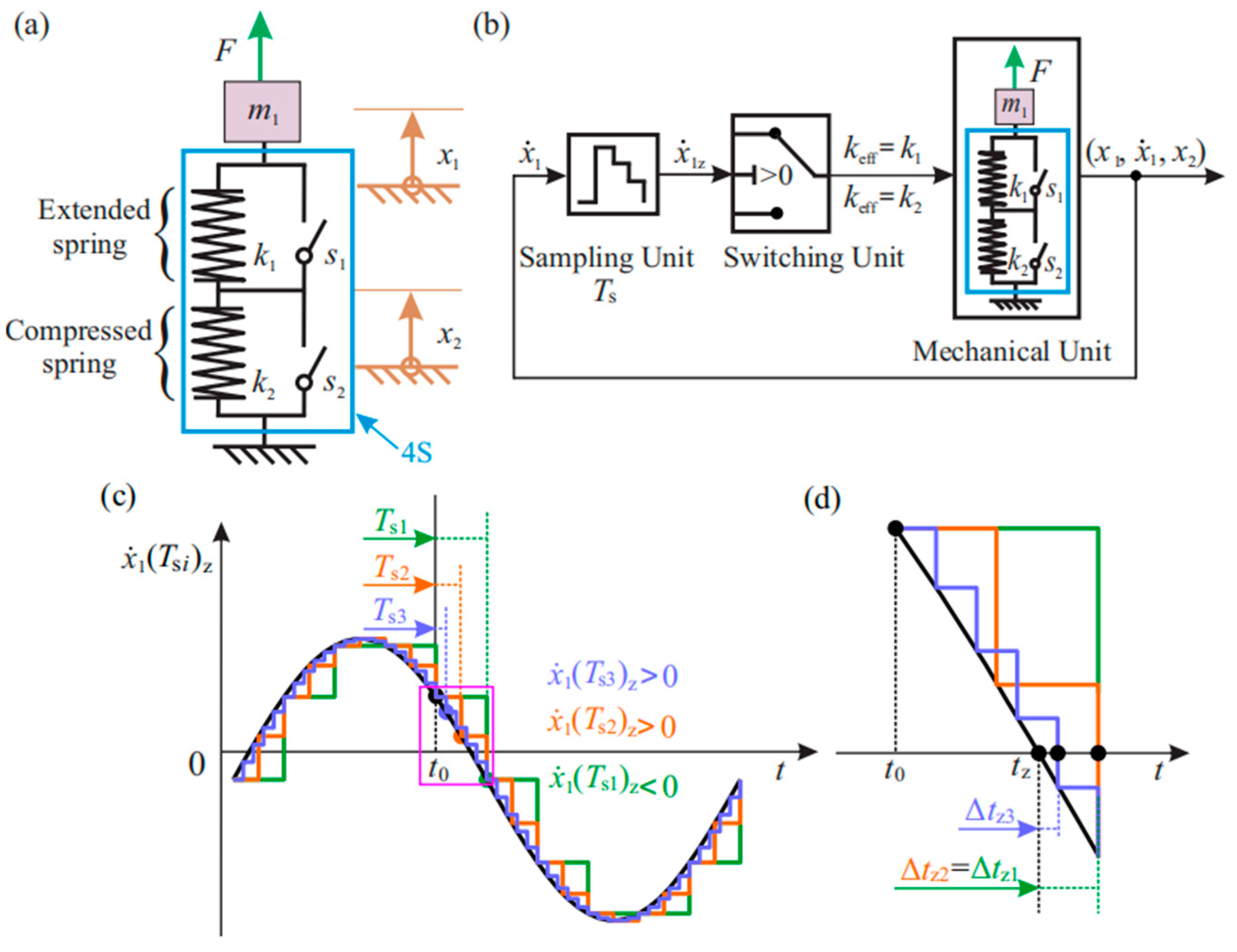
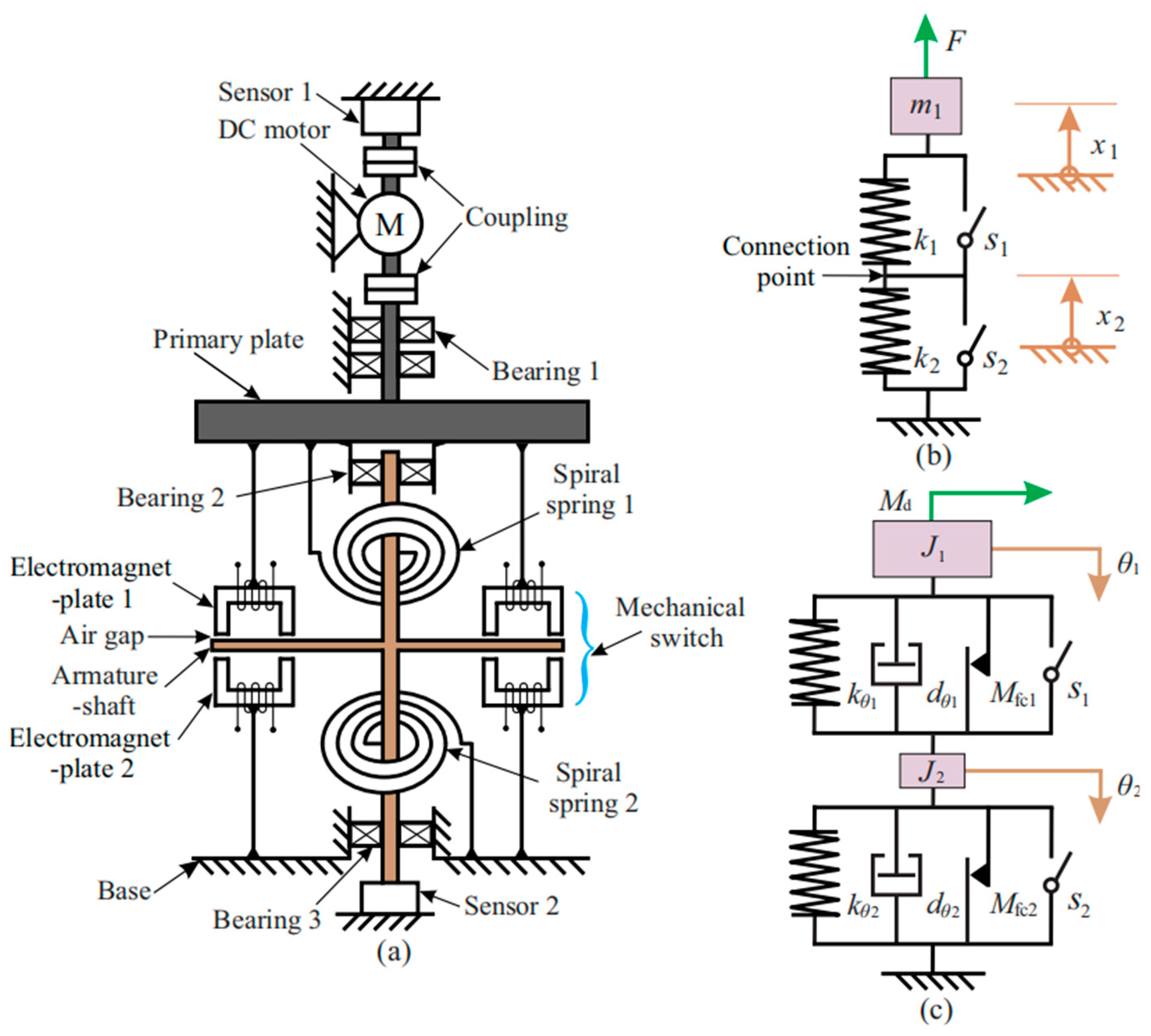
3.1. Principle of the Experimental 4S

A compact rotational experimental 4S with a low natural frequency is shown in Figure 2a. Figure 2b is a reference from a previous analysis and Figure 2c shows a model of the experimental 4S. A primary plate and the attached components work as a load J1 and a DC motor provides a disturbance torque M d as an excitation. In this rotational system, the two springs are spiral springs and may have slightly different stiffness values, k1 and k2, due to manufacturing tolerance. A switch in a mechanical system is more demanding to implement. The basic concept is to use a dry friction torque to clamp two parts together. This requires a normal force, which is built up by electromagnetic forces on an axially moving—and, in some cases, also rotating—armature. Differing from the models on the right in Figure 2, the experimental 4S uses a single alternating switch instead of two simple switches; that is, both electromagnet plates share the same armature shaft, which is attracted to close a switch. This configuration adds an inherent limitation according to which only one switch can be closed at once. However, this limitation has also been used explicitly in previous simulations. The symbols s1 and s2 represent the logic values of each switch [19]. The armature shaft corresponds to the connection point of the two springs in Figure 2b and its small moment of inertia J2 can be ignored compared to J 1 . The other ends of the springs are connected to the base and the primary plate, respectively. The three bearing blocks help to indicate the vertical axis of rotation. Sensors at the top and bottom measure the rotations θ 1 and θ 2 , as marked in Figure 2c. With both switches open, there are two independent rotating assemblies in the experimental setup: the small one is the armature shaft and the large one is composed of the DC motor’s rotor, the coupling, the primary plate and electromagnet plate 1.
The operation principle of the system can be described as follows. To close switch 2 and open switch 1, for example, electromagnet plate 2 is powered on. Electromagnetic forces connect the armature shaft to the base via dry friction torque. Consequently, spring 1 is active and spring 2 is blocked and, finally, the armature shaft does not rotate. When both switches alternatively switch, electromagnet plate 1 is powered on and electromagnet plate 2 powered off. The electromagnetic forces produced move the armature shaft to the primary plate and connect them. In such cases, spring 2 is active and spring 1 is blocked and, finally, the armature shaft rotates together with the large rotating assembly.

3.2. Modeling of the Experimental 4S

For the simulation, the model shown in Figure 2c was augmented. Based on the previously published 4S, shown in Figure 2b, the following two effects were added to the model: viscous damping d θ 1 and d θ 2 of surrounding air and dry friction torques M fc 1 and M fc 2 , mostly from bearings or sensors. The rotation angles of the armature shaft and the primary plate are θ 1 and θ 2 , respectively. A switching law evaluates the primary plate’s direction of rotation. This requires a time-discrete measurement θ ˙ 1 z of its angular velocity θ ˙ 1, with sampling time T s . The active spring is selected according to:
k eff = { k θ 1   if   θ ˙ 1 z 0   while   switch   1   is   open   and   switch   2   is   closed   k θ 2   if   θ ˙ 1 z < 0   while   switch   1   is   closed   and   switch   2   is   open   .
The deformations u 1 and u 2 of the springs:
u 1 = θ 1 θ 2   ,   u 2 = θ 2 0   ,
are defined as independent changing states for the main cases with variable structures. For case 1, with a positive time-discrete velocity, spring 1 is active and switch 2 closed. The equation of motion reads as follows:
J 1 θ ¨ 1 + d θ 1 θ ˙ 1 + M fc 1 sign θ ˙ 1 + k θ 1 u 1 = M d ( t )   ,   θ 2 = θ 2 ( t sw )   ,
where t is time, t sw is the last switching time moment and the right equation’s right side means that θ 2 remains unchanged. For case 2, with a negative time-discrete velocity, spring 2 is active and switch 1 closed. The equation of motion with J 2 neglected entirely, because J 2 J 1 , is as follows:
J 1 θ ¨ 1 + d θ 2 θ ˙ 2 + M fc 2 sign θ ˙ 2 + k θ 2 u 2 = M d ( t )   ,   θ 2 = θ 1 [ θ 1 ( t sw ) θ 2 ( t sw ) ]   ,
For case 3, due to the occurrence of a switching delay time, both switches can be open and both springs can be active at once. A coupled set of equations holds. This case is not considered in the model, which assumes instant switching without a delay time. The harmonic disturbance torque M d is:
M d ( t ) = M ^ d sin ( Ω t )   ,
where M ^ d is the amplitude of the disturbance torque and Ω is the disturbance frequency. The natural frequencies in the main cases 1 and 2 for the undamped system are given by:
ω 01 = k θ 1 J 1   and ω 02 = k θ 2 J 1 + J 2   .  
For both cases with J 2 = 0 , because J 2 J 1 and since k θ 1 k θ 2 is set by design, the same ω 0 is defined as:
ω 0 = ω 01 ω 02  
The relationship between the disturbance frequency Ω , sampling frequency ω s and natural frequency ω 0 is defined by the dimensionless sampling frequency η s   and the dimensionless disturbance frequency η d :
η d = ω 0   ,   η s = ω s ω 0   ,   ω s = 2 π T s   .  

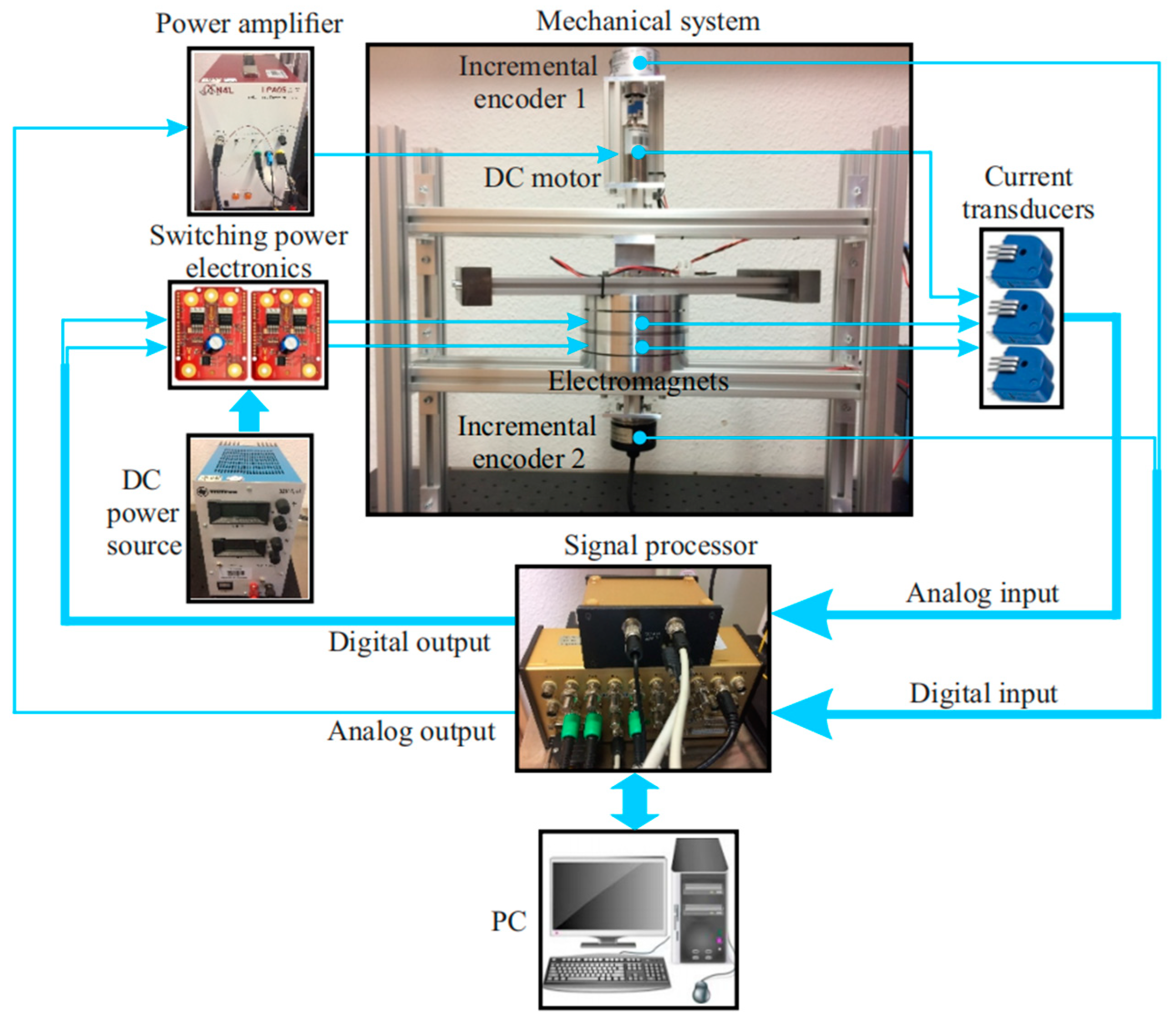
3.3. Setup of the Experimental 4S

The final design of the experimental 4S is shown in Figure 3a. To avoid radial deflections of the springs due to gravity, the experimental 4S rotates around a vertical axis, which is fixed on an aluminum frame (5). For a low natural frequency, the moment of inertia J1 is increased with an auxiliary rotation block (6), which is added at a distant radial position. Thus, the moment of inertia of the armature shaft J 2 , (10) is only 6.5% of J 1 (2, 6, 7, 9), confirming the approximation of Equation (8). Two incremental encoders (1 and 12) are used for the rotation angle measurement of the primary plate and armature shaft. A DC motor (3), which has the advantages of low cost, simple control and high reliability, produces the disturbance excitation in Equation (6). The 4S is marked with a dashed black line and its internal structure is shown with a CAD cross-sectional view in Figure 3e. The main components are the two spiral springs (13 and 24), two electromagnet plates (9 and 11), the armature shaft (10), and the air gap (14). Ball bearings are used to obtain only small dry friction torques M fc and achieve energy conversion and not energy dissipation. Spring 13 in Figure 3d is connected to electromagnet plate 1 through a bolt (19) and plugged in a groove (18) of a cylinder, which is clamped to the shaft (21).
One of the electromagnet plates attracts the armature shaft and produces the normal force for the clamping friction torque, which closes a switch and changes the variable structure. The air-gap side of an electromagnet plate is shown in Figure 3b. A circular aluminum housing with eight U-shaped iron cores (15) and a coil (16) are embedded in transparent epoxy (17). The eight iron cores are symmetrically distributed in the circumferential direction to reduce the magnetic saturation of the armature when an electromagnet is powered on. Additionally, the iron cores use a stacked metal sheet structure in order to decrease eddy current losses while maintaining a good flux-carrying ability. The armature shaft in Figure 3c mainly consists of the armature (20) and shaft (21), which are connected through a triangle spring (22) and three bolts (23). The armature must be able to move freely from one electromagnet plate to the other in the axial direction. Therefore, the triangle spring was designed to have a low axial stiffness. Moreover, the rotational stiffness must be high to transmit the spring’s torque. The triangle spring allows for high circumferential forces as tension and provides low axial bending forces. To achieve a shorter delay time when switching, the armature mass is minimal and the electromagnetic force has to build up quickly, which requires sufficient voltage.

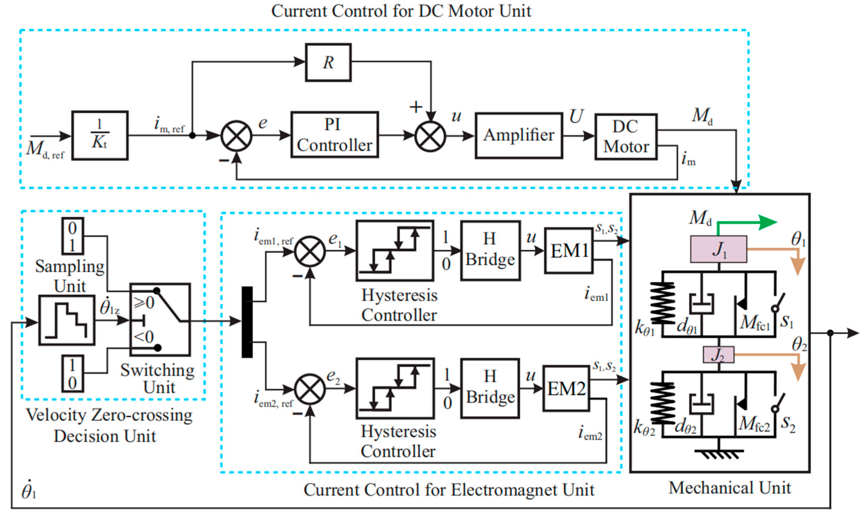
3.4. Power Electronics and Control of the Experimental 4S

This section describes the choice and control of power electronics for the DC motor and both electromagnets. To validate the vibration reduction performance and vibration energy conversion of the 4S, a harmonic disturbance excitation torque must be exactly given. Considering the cost and difficulty of direct torque control and the linear relationship between the current and output torque of a DC motor, a current control scheme was chosen here. First, the system dynamics of a DC motor can be given by
M d = K t i m   ,
and
L d i m d t + R i m + K e θ ˙ 1 = U   ,
where M d is the DC motor’s output torque and L ,   R ,   K t and K e are the electric inductance, electric resistance, torque coefficient and electromotive force coefficient, respectively. The current control for the DC motor unit uses a PI controller for the current, as shown in Figure 4, where i m , ref is the required current of the DC motor, determined by the reference torque M d , ref via 1 / K t , as given by Equation (10). A model-based voltage feedforward control is applied to decrease the load on the controller. As θ ˙ 1 of the primary plate and the disturbance frequency Ω are very low, only the resistance R has to be considered, according to Equation (11).
In the current control for the electromagnet unit in Figure 4, each electromagnet (EM) is powered by an H bridge circuit, for which we chose the Motor Control Shield with BTN8982TA from Infineon Company. These switching power electronic controllers have low power losses in the transistors and are controlled by hysteresis controllers. The logic signal from a hysteresis controller determines whether the H bridge produces positive or negative voltage, which is then applied to an electromagnet. After the air gap δ   vanishes on one side and high electromagnetic forces have built up, the logic values of each switch s 1 and s 2 are defined. The velocity zero-crossing decision unit generates the reference current for each electromagnet, i m 1 , ref or i m 2 , ref , based on its switching law to activate the desired spring.
Finally, the complete experimental system was built as depicted in Figure 5. Two incremental encoders measure the angular positions θ 1 and θ 2 . Three current transducers enable current acquisition for the DC motor and both electromagnets. The controllers are implemented on an ADwin Gold signal processor, which also communicates with a PC for data acquisition. The output control signals from the signal processor are connected to a power amplifier and switching power electronic controllers, respectively.

4. Measurement of Physical Properties of the Experimental 4S

For the simulation, the parameters of the experimental 4S were identified, and the delay time when switching was measured to ensure the correct operation of the switches. The results are shown in this section.

System Parameter Identification

An excited quasi-static low-frequency oscillation, η d 0.1 , made it possible to neglect viscous damping and inertial effects in the system (see Equations (4) and (5)), which helped in the identification of dry friction and stiffness. After oscillations due to initial conditions had subsided, the results inFigure 6a and Figure 7a were obtained. Two loops were plotted to show the experiments’ reproduction abilities, as denoted by the blue and orange points. The relationship between the angular displacement θ 1 and the driving motor torque M d was identified. Linear regression yielded the upper and lower black lines. The vertical distance equals the dry friction torque multiplied by two and the slope equals the stiffness. For example, in case 1 (Figure 6a), the lines are expressed by
M d = 0.1513 θ 1 + 0.0109   ,   and   M d = 0.1489 θ 1 0.0065   .
To get the viscous damping, the response of the experimental 4S to non-zero initial conditions was measured and numerical simulations, considering viscous damping and dry friction, were carried out in MATLAB/Simulink. The experimental results are shown in Figure 6b and Figure 7b. To ensure it was comparable with the experiment, the damping ratio D = d eff / ( 2 k eff J 1 ) ) of the model was adjusted iteratively until good agreement was obtained. Both moments of inertia J 1   and J 2 were computed through the distribution and density of the construction materials in CAD/Solidworks, but only J 1 of case 1 was used in the simulation. All parameters are given in Table 1. The natural periods of the damped system were T exp in the experiment and T sim in the simulation. The error between the simulation and experiment was small enough. More time was required for the motion of the armature, which was not modeled in the simulation. Figure 8 shows the measured current profiles for each electromagnet during the experiment. After the new reference current was hit, around zero, the current profiles indicated the chattering of the off-current’s hysteresis controller to compensate for the back EMF until motion stopped abruptly. They also showed the on-current’s down spike, which was triggered when the armature’s eddy currents strongly coupled to the electromagnet’s coil via increased mutual inductance after the air gap on the attracting side vanished. The delay times t d 1 and t d 2 of the armature motion were shorter than the chosen sampling time T s , which meant that the previous switching was safely completed before the next switching was triggered.

5. Experimental Validation of Vibration Control

A previous simulation analysis used a dimensionless sampling frequency of η s = 1000 , which was high enough to avoid switching delays. Critical values that deteriorate the performance are those below 100. Considering the delay times t d of the switches, the default η s was set to 100 in the experiments here. The natural frequency ω 0 was 1.113 rad/s. Combining this with Equation (9), the sampling frequency ω s equaled 111.3 rad/s and the sampling period T s approximated to 56.45 ms.

5.1. Harmonic Disturbance

To validate that the proposed system converts vibration energy and reduces vibration, here a harmonic disturbance torque ( M ^ d = 0.05 Nm , η d = 3 ) was set to act on the primary plate, according to Equation (6). As a reference, the experimental 4S without a control (case 1), which behaves like a passive damped system, was set to oscillate according to the pink line in Figure 9, where the vertical axis denotes different coordinates containing the deformations of each spring, u1 and u2, and the position of the primary plate θ1, and the horizontal axis is the time t. For the experimental 4S with a control, the experimental and simulation results are shown colored. The results clearly indicate that the deformations of spring 1 and spring 2 increased positively and negatively, respectively, while the primary plate stayed at a non-zero equilibrium-like position. It can be concluded that the 4S indeed converts potential energy. While the 4S converts energy, its spring torques increase. After a few seconds of energy conversion, the spring torques are large enough to reduce vibrations. These reduced vibrations also lower the energy conversion power. As a result, the slope of the deformations decreases. The experiment and simulation matched well at the beginning but a small difference became apparent later. This is reasonable, as unknown disturbances and small switching decision errors come out in the practical system due to the switching delay. Consequently, many small errors can over time add up to a larger error e ( e 0.14 rad as marked in Figure 9) in the system response.

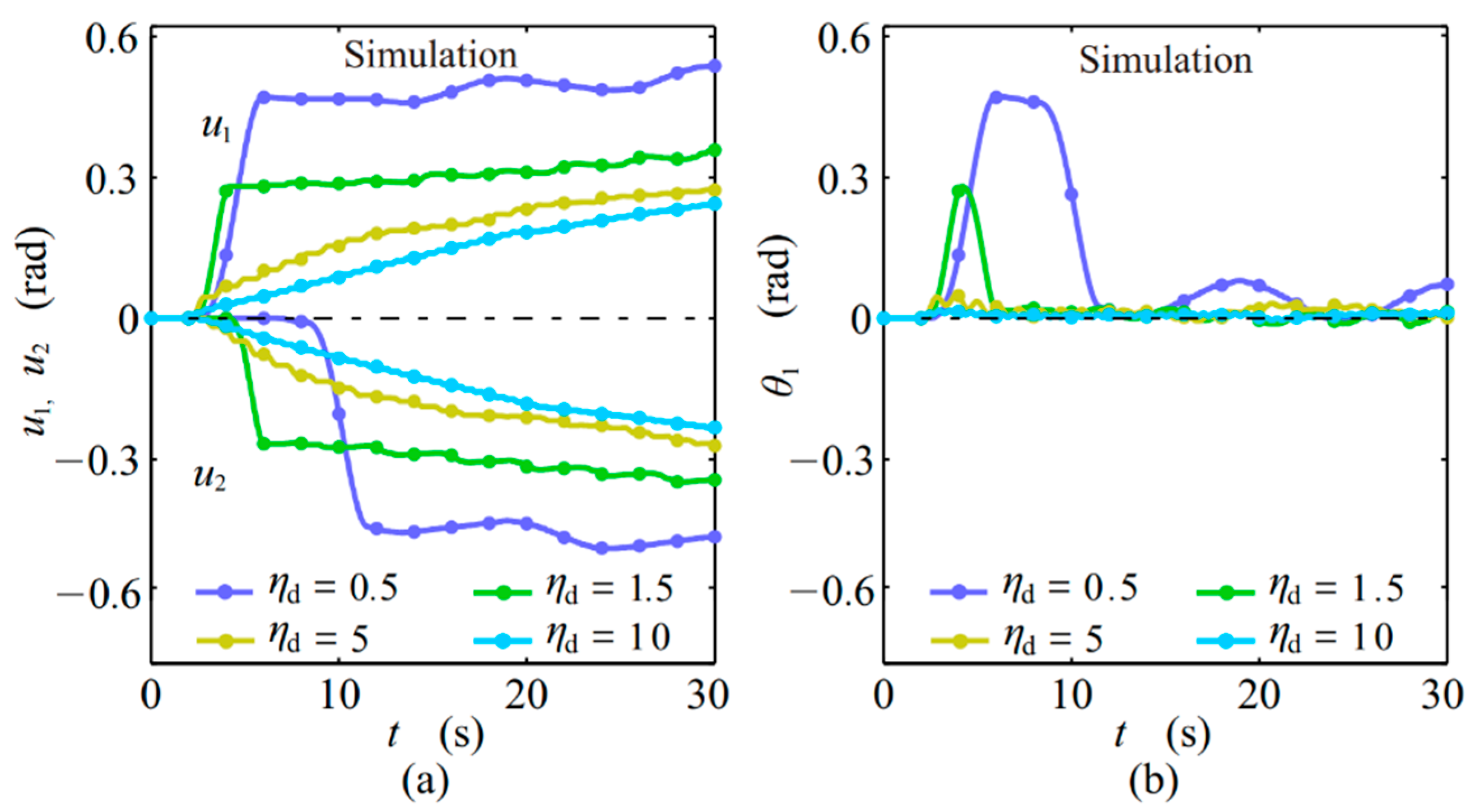
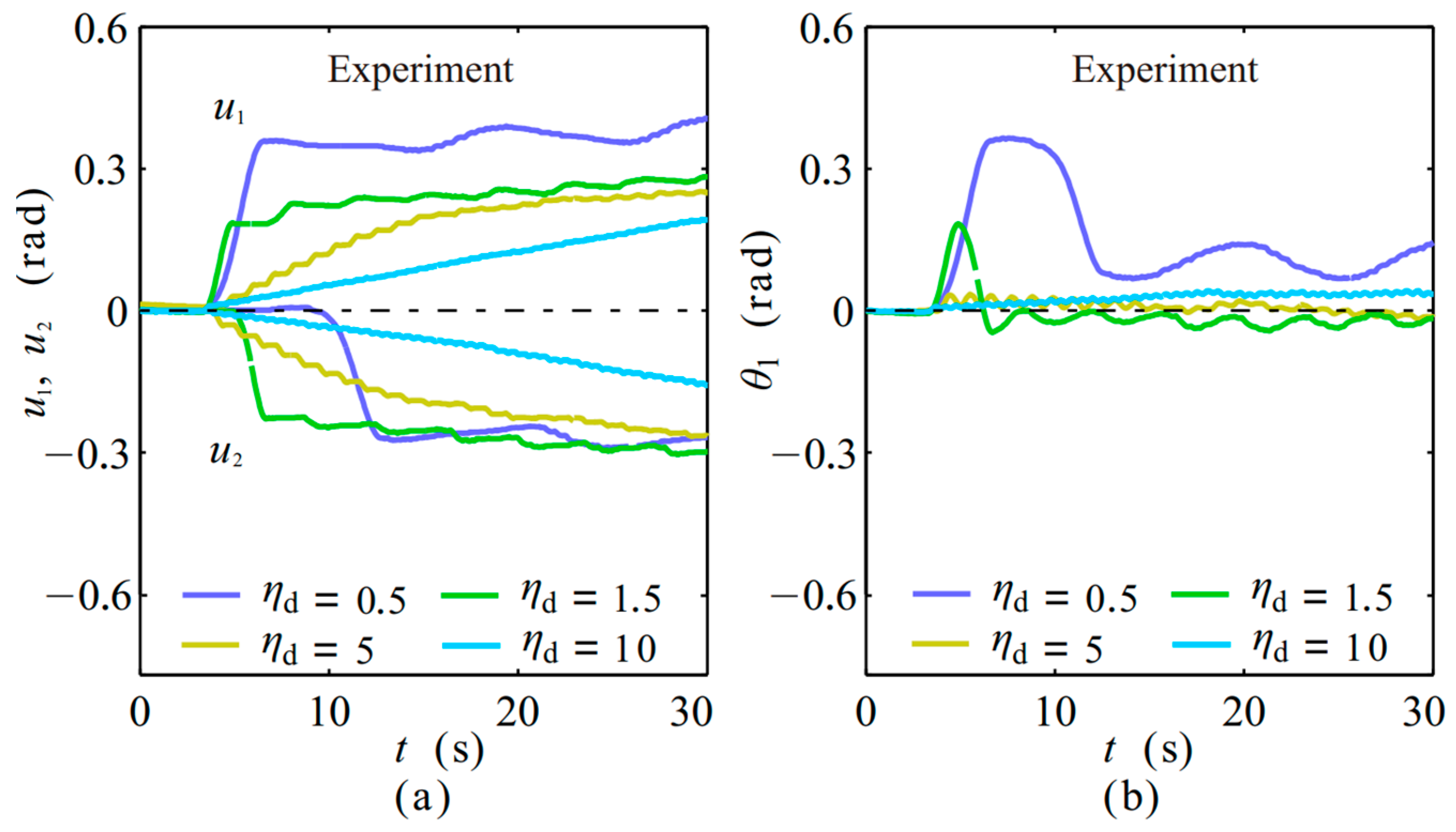
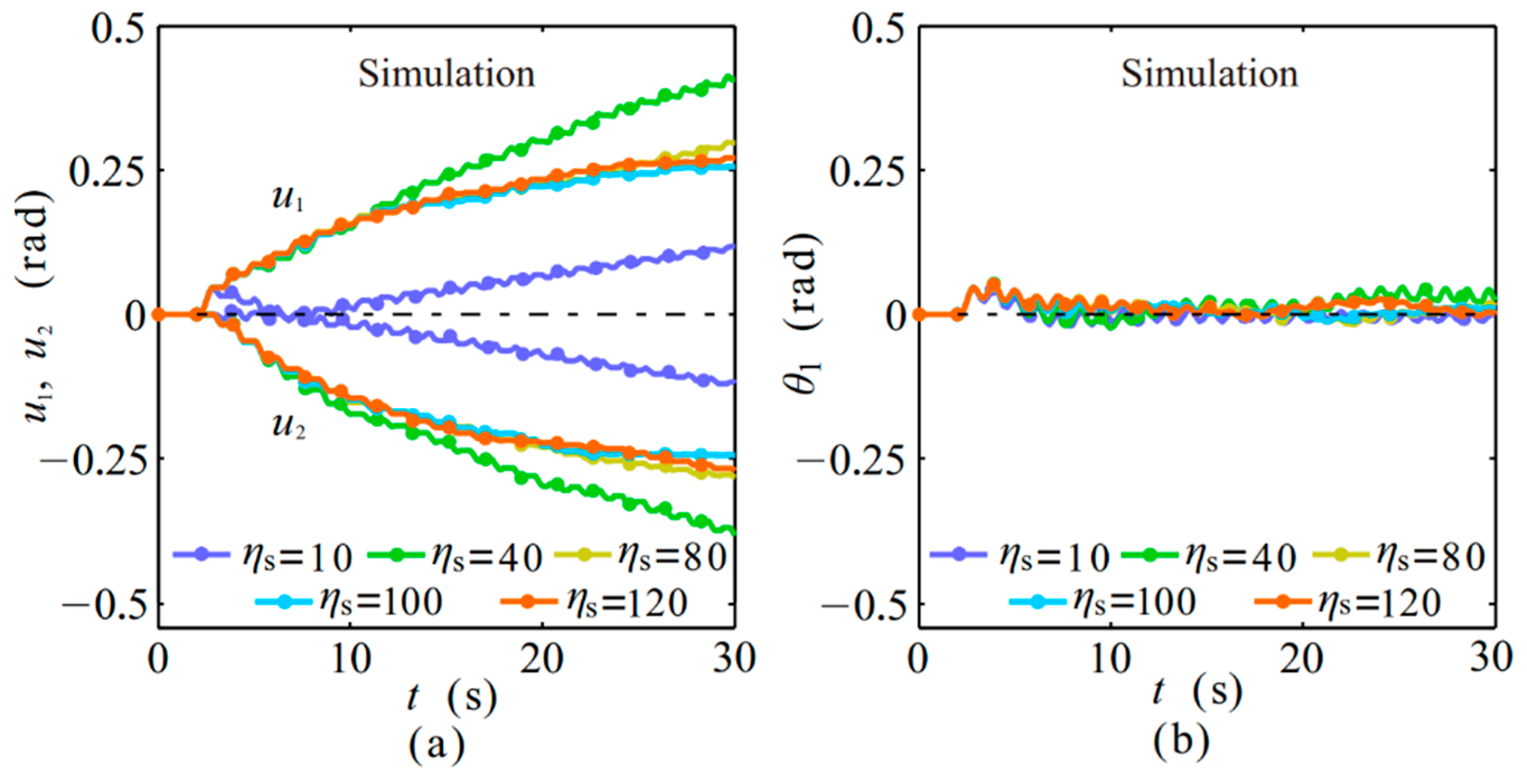
5.2. Parameter Variation

The energy conversion and vibration reduction performance of the 4S was compared in an experiment and simulation for different dimensionless disturbance frequencies η d , disturbance amplitudes M ^ d and dimensionless sampling frequencies η s .
Figure 10 and Figure 11 show the experiment and simulation results for harmonic disturbances with different dimensionless disturbance frequencies. Oscillation amplitudes of θ1 decreased with increasing dimensionless disturbance frequencies because of the passive low-pass filtering property of second-order systems. The deformations u 1 and u 2 of the two springs increased more slowly, which means that less potential energy was converted. This was because the low oscillation amplitude resulted in a low energy conversion power into the springs. The shapes of the experiment and simulation agreed quite well. Imperfections, like unwanted slip in the clamping dry friction contacts, could trigger offsets in the position when the force or deformation was too large.
Figure 12 and Figure 13 show the simulation and experiment results for harmonic disturbances with different disturbance torque amplitudes. It can obviously be concluded that the system’s vibration energy conversion increased with the disturbance torque, but the primary plate remained at an equilibrium-like position.
As mentioned previously, the sampling period Ts determines the switching delay, which strongly influences the switching decision error and further influences the switching system performance. Thus, Figure 14 and Figure 15 show the simulation and experiment results for harmonic disturbances with different dimensionless sampling frequencies. They show that an overly low sampling period, for instance η s = 10 , lowered the energy conversion power and did not reduce vibrations, because the high sampling period increased the switching determination error. With an increasing dimensionless sampling frequency, the energy conversion power initially increased. When the sampling period was large enough and energy had been converted, the vibration reduction lowered the further energy conversion power. The larger switching decision error for η s = 40 prevented this decrease of energy conversion power at the cost of less vibration reduction. Additionally, the experiment and simulation did not have the same exact initial conditions.
This can be seen, for example, in the red line, for which, in the experiment, spring 2 was activated first, while in the simulation, spring 1 was activated first. Very small differences in the initial conditions around zero are enough to trigger larger differences in the 4S dynamic behavior because of the nonlinearity of the switching. This non-linearity generates a large difference in the output from a small difference in the input. Overall, the experiment and simulation agreed well and the feasibility of the semi-active vibration control concept was proven.

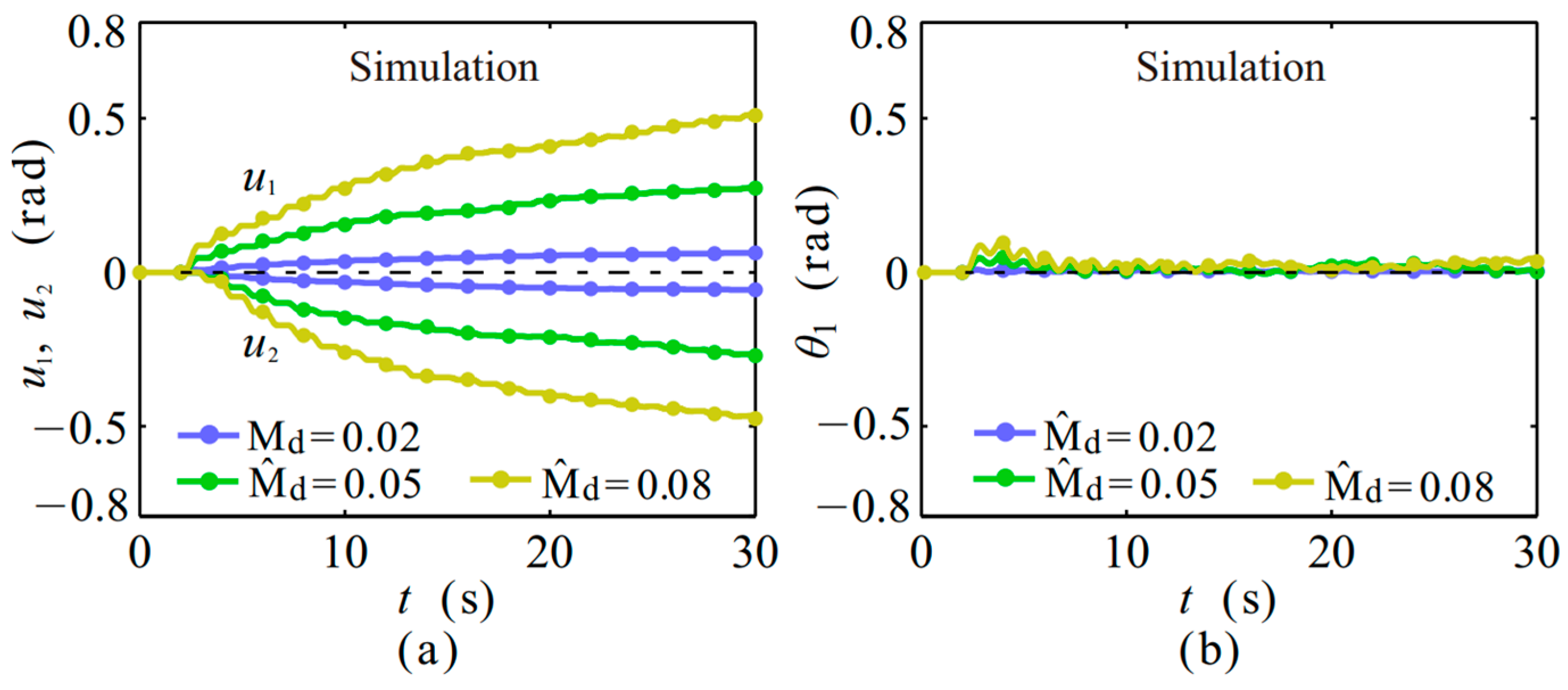
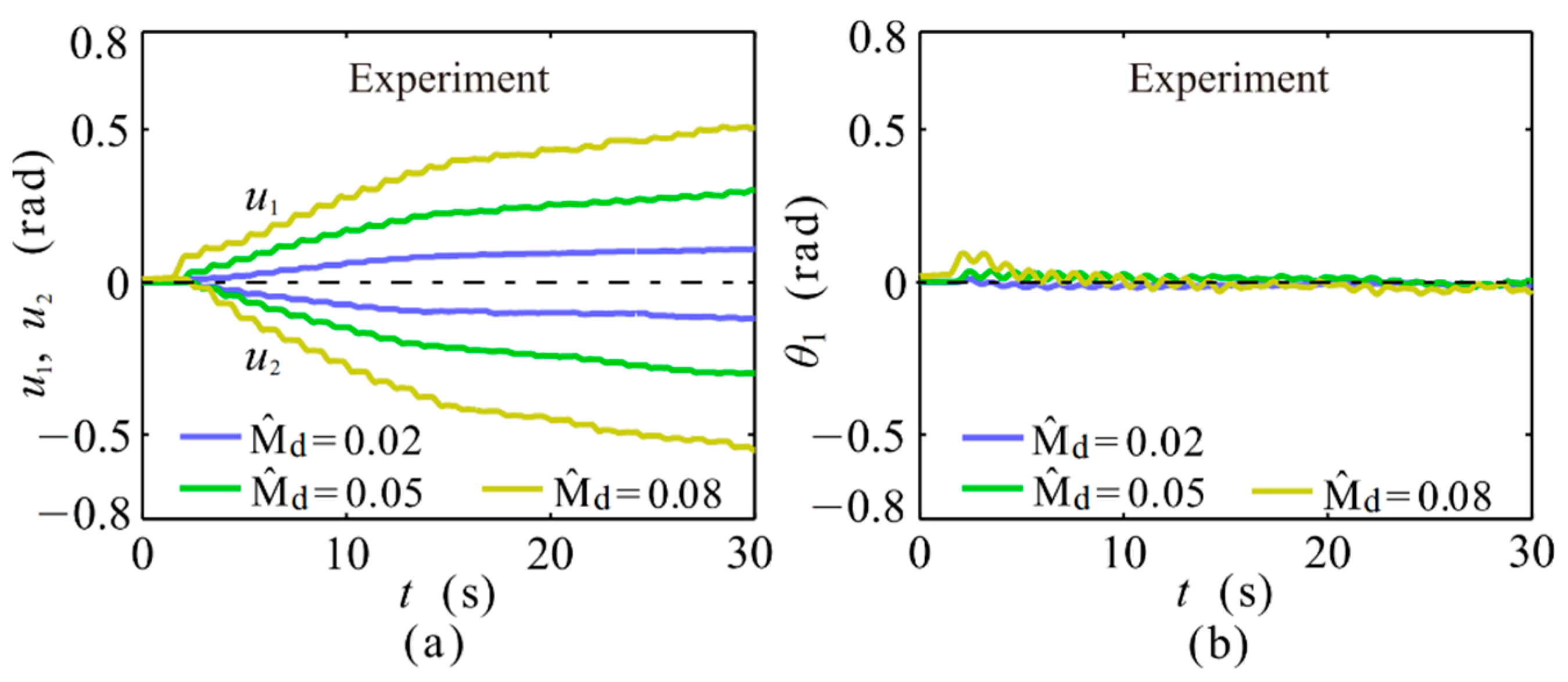
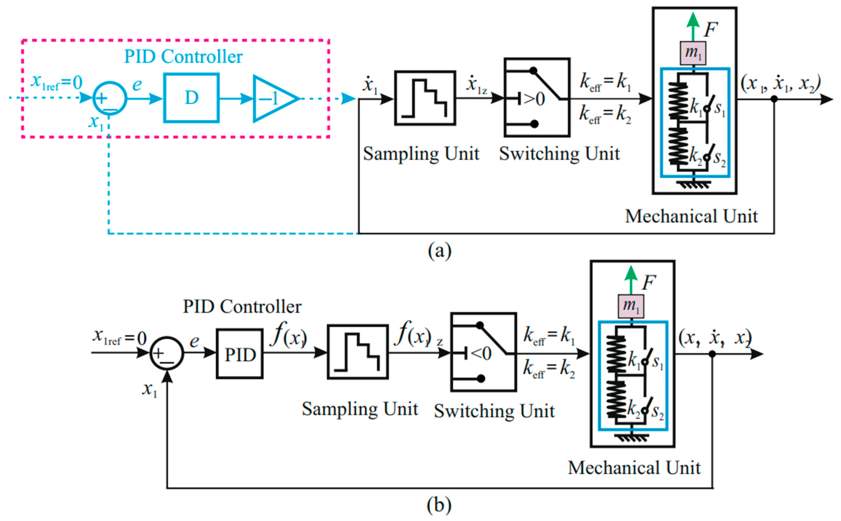
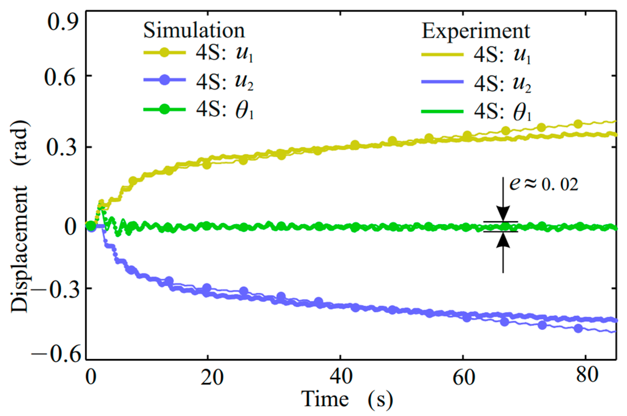
6. Improved Semi-Active Vibration Control Strategy

As depicted in Figure 9, compared with the numerical analysis, the experimental 4S could not reach an equilibrium-like position due to unknown system disturbances in practice. To obtain better repositioning for vibration reduction, the system should be not influenced by other disturbances. Since the 4S is capable of converting and storing vibration energy and then acting as an actuator, which enables position feedback and active positioning, position feedback control was tested. Actually, the velocity zero-crossing switching law acts as the derivative control (D control) for the mass displacement x 1 with x 1 ref = 0 , as depicted in Figure 16a; therefore, a complete PID control switching law was further put forward, as illustrated in Figure 16b. Here, x1 and x1ref in translation correspond to θ 1 and θ 1 ref in rotation.
As a new switching determination, the PID-controlled error between the state variable and the reference position, x 1 ref x 1 , is brought into
f ( x 1 ) = K p ( x 1 ref     x 1 ) + K i 0 t ( x 1 ref x 1 ( τ ) ) d τ + K d d ( x 1 ref     x 1 ) d t
and the stiffness switching strategy is modified and reads
k eff = { k 1   if   f ( x 1 ) < 0 k 2   if   f ( x 1 ) 0   .
Considering both the positioning demand and vibration energy conversion level, the proportional (P), integral (I) and derivative (D) coefficients must be set carefully. In contrast to a linear PID control system, because of the application of a zero-crossing determination on the switching system, changes in PID coefficients of the same proportion will not affect the final system response. In comparison to the system response related to the velocity zero-crossing switching law, as demonstrated in Figure 9, the system with a PID control switching law benefits from position feedback and enables a better zero equilibrium-like position ( e 0.02 ) as marked in Figure 17.

7. Conclusions

A rotational electromagnetic semi-active switching stiffness vibration control system together with an improved stiffness switching law was presented in this paper for the first time. It was modelled, designed and built. Experiments showed the feasibility of the semi-active vibration control concept for the conversion of vibration energy and reduction of vibrations. The practical implementation of the concept required very fast mechanical switches. Our experimental 4S was designed to be slow enough that the delay time of 20 ms could be considered fast. This means that possible applications must have a low natural frequency or else a faster switch will be needed. Note that, like power electronics switching, overly slow switching also increases energy losses. Both switches open for about 20 ms and during that time the armature accelerates, which converts the potential energy of the springs into kinetic energy in the armature. When the dry friction-based switch closes at different angular velocities, the angular momentum of the whole system has to be conserved. A short time period with sliding dry friction causes a loss of kinetic energy during this perfectly inelastic collision. Furthermore, a PID position feedback control-based switching law was further applied and experimentally verified to improve the repositioning accuracy of the disturbed system with almost no positioning error. In practice, an electromagnet plate could be used in a rotational vibration control system instead of the piezoelectric actuators with fast switching action used in translation systems. Additionally, the potential energy temporarily stored in the switching system could be used in a robotic leg or in some kinds of toys for an auxiliary skipping action.

Author Contributions

Conceptualization, M.D. and C.M.; methodology, C.M. and M.D.; software, C.M. and M.D.; validation, M.D., C.M. and T.S.; formal analysis, C.M. M.D.; investigation, C.M.; resources, C.M. and T.S.; data curation, C.M. and M.D.; writing—original draft preparation, C.M.; writing—review and editing, M.D. and C.M.; visualization, C.M.; supervision, T.S.; project administration, C.M.; funding acquisition, C.M. All authors have read and agreed to the published version of the manuscript.

Funding

This research was funded by Natural Science Foundation of Shanxi Province, grant number 2020JQ-048 and Postdoctoral Research Foundation of China, grant number 2020M673376 and The APC was funded by and Natural Science Foundation of Shanxi Province.

Conflicts of Interest

The authors declare no conflict of interest.

References

  1. Liu, C.; Jing, X.; Daley, S.; Li, F. Recent advances in micro-vibration isolation. Mech. Syst. Signal Process 2015, 56, 55–80. [Google Scholar] [CrossRef]
  2. Lee, C.Y.; Pai, C.A. Design and implementation of tunable multi-degree-of-freedom vibration absorber made of hybrid shape memory helical springs. J. Intel. Mat. Syst. Str. 2016, 27, 1047–1060. [Google Scholar] [CrossRef]
  3. Du, H.; Li, W.; Zhang, N. Semi-active variable stiffness vibration control of vehicle seat suspension using an mr elastomer isolator. Smart Mater. Struct. 2011, 20, 105003. [Google Scholar] [CrossRef]
  4. Scheidler, J.; Asnani, V.; Dapino, M. Dynamically tuned magneto-strictive spring with electrically controlled stiffness. Smart Mater. Struct. 2016, 25, 1–10. [Google Scholar] [CrossRef] [Green Version]
  5. Bajkowski, J.; Dyniewicz, B.; Bajer, C. Semi-active damping strategy for beams system with pneumatically controlled granular structure. Mech. Syst. Signal Process 2016, 56, 55–80. [Google Scholar] [CrossRef]
  6. Wu, T.; Lan, C. A wide-range variable stiffness mechanism for semi-active vibration systems. J. Sound Vib. 2016, 363, 18–32. [Google Scholar] [CrossRef]
  7. Pu, H.; Peng, S.Y.; Meng, K.; Zhao, J.; Xie, R.; Huang, Y.; Sun, Y.; Yang, Y.; Xie, S.; Luo, J.; et al. Multi-layer electromagnetic spring with tunable negative stiffness for semi-active vibration isolation. Mech. Syst. Signal Process 2019, 121, 942–960. [Google Scholar] [CrossRef]
  8. Winthrop, M.F.; Baker, W.P.; Cobb, R.G. A variable stiffness device selection and design tool for lightly damped structures. J. Sound Vib. 2005, 287, 667–682. [Google Scholar] [CrossRef]
  9. Ledezma-Ramirez, D.F.; Ferguson, N.S.; Brennan, M.J. An expeimental switchable stiffness device for shock isolation. J. Sound Vib. 2012, 331, 4987–5001. [Google Scholar] [CrossRef]
  10. Dyniewicz, B.; Bajkowski, J.M.; Bajer, C. Semi-active control of a sandwich beam partially filled with magnetorheological elastomer. JSME Intel J. C 2015, 60, 695–705. [Google Scholar] [CrossRef]
  11. Onoda, J.; Endo, T.; Tamaoki, H.; Watanbe, N. Vibration suppression by variable-stiffness members. AIAA J. 1991, 29, 977–983. [Google Scholar] [CrossRef]
  12. Wang, X.; Gordaninejad, F. Performance of a new magnetorheological elastomer isolation system. Smart Mater. Struct. 2014, 23, 045014. [Google Scholar]
  13. Irie, T.; Shingu, K. Vibraion control of variable rigidity frame structure by magnetic clutch. J. Comput. Sci. Technol. 2008, 2, 393–400. [Google Scholar] [CrossRef] [Green Version]
  14. Leavitt, J.; Bobrow, J.E.; Jabbari, F. Design of a 20,000 pound variable stiffness actuator for structural vibration attenuation. Shock. Vib. 2008, 15, 687–696. [Google Scholar] [CrossRef]
  15. Opie, S.; Yim, W. Design and control of a real-time variable stiffness vibration isolator. In Proceedings of the 2009 IEEE/ASME International Conference on Advanced Intelligent Mechatronics, Singapore, 14–17 July 2009; pp. 380–385. [Google Scholar]
  16. Tran, T.; Liu, K. Time-delay control of a switchable stiffness system. J. Sound Vib. 2015, 20, 1–16. [Google Scholar] [CrossRef]
  17. Nguyen, X.; Komatsuzaki, T.; Iwata, Y.; Asanuma, H. Modeling and semi-active fuzzy control of magnetorheological elastomer-based isolator for seismic response reduction. Mech. Syst. Signal Process 2018, 101, 449–466. [Google Scholar] [CrossRef] [Green Version]
  18. Gu, X.; Yu, Y.; Li, Y.; Li, J.; Askari, M.; Samali, B. Experimental study of semi-active magnetorheological elastomer base isolation system using optimal neuro fuzzy logic control. Mech. Syst. Signal Process 2019, 119, 380–398. [Google Scholar] [CrossRef]
  19. Min, C.; Dahlman, M.; Sattel, T. A concept for semi-active vibration control with a serial-stiffness-switch system. J. Sound Vib. 2017, 405, 234–250. [Google Scholar] [CrossRef]
  20. Min, C.; Dahlman, M.; Sattel, T. A semi-active shock isolation concept with serial-stiffness-switch system. J. Sound Vib. 2019, 445, 117–131. [Google Scholar] [CrossRef]
  21. Gao, W.; Wang, Y.; Homaifa, A. Discrete-time variable structure control systems. IEEE T. Ind. Electron. 2002, 42, 117–122. [Google Scholar]
  22. Yamaguchi, H.; Yashima, M. Vibration reduction and isolation performance for on-off control of a friction force at a spring support. J. Sound Vib. 1997, 208, 729–743. [Google Scholar] [CrossRef]
  23. Yong, C.; Zimcik, D.G.; Wickramsinghe, V.K.; Nitzsche, F. Development of the smart spring for active vibration control of helicopter blades. J. Intel. Mat. Syst. Str. 2004, 15, 37–47. [Google Scholar] [CrossRef]
  24. Sun, S.; Tang, X.; Li, W.; Du, H. Advanced vehicle suspension with variable stiffness and damping mr damper. In Proceedings of the 2017 IEEE International Conference on Mechatronics (ICM), Churchill, VIC, Australia, 13–15 February 2017; pp. 444–448. [Google Scholar]
  25. Greiner-Petter, C.; Tan, A.S.; Sattel, T. A semi-active magnetorheological fluid mechanism with variable stiffness and damping. Smart Mater. Struct. 2014, 23, 1–10. [Google Scholar] [CrossRef]
  26. Deng, H.; Wang, M.; Han, G.; Zhang, J.; Ma, M.; Zhong, X.; Yu, L. Variable stiffness mechanisms of dual parameters changing magnetorheological fluid devices. Smart Mater. Struct. 2017, 26, 125014. [Google Scholar] [CrossRef]
  27. Dong, X.; Liu, W.; An, G.; Zhou, Y.; Yu, J.; Lin, Q. A novel rotary magnetorheological flexible joint with variable stiffness and damping. Smart Mater. Struct. 2018, 27, 105045. [Google Scholar] [CrossRef]
  28. Deng, H.; Deng, J.; Yue, R.; Han, G.; Zhang, J.; Ma, M.; Zhong, X. Design and verification of a seat suspension with variable stiffness and damping. Smart Mater. Struct. 2019, 28, 065015. [Google Scholar] [CrossRef]
  29. Ramaratnam, A.; Nader, J. A switched stiffness approach for structural vibration control: Theory and real-time implementation. J. Sound Vib. 2006, 291, 258–274. [Google Scholar] [CrossRef]
  30. Alotaibi, S.A.; Al-Ajmi, M.A. A variable stiffness approach to vibration control. Int. J. Comput. Inf. Eng. 2014, 8, 565–567. [Google Scholar]
  31. Tran, T. Vibration Control Using Switchable Stiffness. Master’s Thesis, Lakehead University, Thunder Bay, ON, Canada, 2014. [Google Scholar]
  32. Du, G.; Huang, X.; Li, Y.; Ouyang, Q.; Wang, J. Performance of a semi-active/passive integrated isolator based on a magnetorheological elastomer and spring. Smart Mater. Struct. 2017, 26, 095024. [Google Scholar] [CrossRef]
  33. Gripp, J.; Rade, D. Vibration and noise control using shunted piezoelectric transducers: A review. Mech. Syst. Signal Process 2018, 112, 359–383. [Google Scholar] [CrossRef]
Figure 1. Schematic illustration of the 4S: (a) 4S with an attached load m1 under force excitation F; (b) lumped controlled 4S; (c,d) switching determination error for the 4S with different sampling period Ts. Black: original signal; green, orange and blue: discretized signals with different sampling periods Ts1, Ts2 and Ts3; (d) partly zoomed-in picture of (c).
Energies 14 05177 g001
Figure 2. (a) Principle of the experimental 4S; (b) translational model of the 4S; (c) rotational model of the experimental 4S.
Energies 14 05177 g002
Figure 3. (a) Photograph of the experimental 4S; (b) electromagnet plate, view from air-gap side; (c) armature shaft; (d) electromagnet plate 1 with spring 1, view from top. 1—incremental encoder 1; 2—coupling; 3—DC motor; 4—bearing block 1; 5—aluminum frame; 6—auxiliary rotation block; 7—primary plate; 8—base; 9—electromagnet plate 1; 10—armature shaft; 11—electromagnet plate 2; 12—incremental encoder 2; 13—spring 1; 14—air gap; 15—U-shaped iron core; 16—coil; 17—epoxy; 18—groove; 19—bolt; 20—armature; 21—shaft; 22—triangle spring; 23—bolts; 24—spring 2. (e) Cross-sectional view of the internal structure of 4S.
Energies 14 05177 g003
Figure 4. Schematic for the control.
Energies 14 05177 g004
Figure 5. Complete experimental system.
Energies 14 05177 g005
Figure 6. Parameter identification results with spring 1 active: (a) excited quasi-static low-frequency oscillation; (b) free oscillation after initial displacement.
Energies 14 05177 g006
Figure 7. Parameter identification results with spring 2 active: (a) excited quasi-static low-frequency oscillation; (b) free oscillation after initial displacement.
Energies 14 05177 g007
Figure 8. Current profiles showing switching delay: (a) electromagnet 1 powered on and electromagnet 2 off; (b) electromagnet 1 powered off and electromagnet 2 on.
Energies 14 05177 g008
Figure 9. Experimental and simulation responses of the 4S under harmonic disturbance, here M ^ d = 0.05   Nm , η s = 100 , and η d = 3 . Solid bold line: experiment results; point-solid line: simulation; yellow: deformation of spring 1, u 1 ; blue: deformation of spring 2, u 2 ; green: position of primary plate, θ 1 .
Energies 14 05177 g009
Figure 10. Serial-stiffness-switch system simulation results for harmonic disturbances under different η d , here M ^ d = 0.05 Nm and η s = 100 . (a) Deformations of the two springs, u 1 and u 2 ; (b) displacement of the primary plate, θ 1 .
Energies 14 05177 g010
Figure 11. Serial-stiffness-switch system experiment results for harmonic disturbances under different η d , here M ^ d = 0.05 Nm and η s = 100 . (a) Deformations of the two springs, u 1 and u 2 ; (b) displacement of the primary plate, θ 1 .
Energies 14 05177 g011
Figure 12. Serial-stiffness-switch system simulation results for harmonic disturbances under different disturbance torque amplitudes M ^ d , here η s = 100 and η d = 3 . (a) Deformations of the two springs, u 1 and u 2 ; (b) displacement of the primary plate, θ 1 .
Energies 14 05177 g012
Figure 13. Serial-stiffness-switch system experiment results for harmonic disturbances under different disturbance torque amplitudes M ^ d , here η s = 100 and η d = 3 . (a) Deformations of the two springs, u 1 and u 2 ; (b) displacement of the primary plate, θ 1 .
Energies 14 05177 g013
Figure 14. Serial-stiffness-switch system simulation results for harmonic disturbances under different dimensionless sampling frequencies η s , here η s = 100 and η d = 3 . (a) Deformations of the two springs, u 1 and u 2 ; (b) displacement of the primary plate, θ 1 .
Energies 14 05177 g014
Figure 15. Serial-stiffness-switch system experiment results for harmonic disturbances under different dimensionless sampling frequencies, here η d = 3 , here η d = 3 and M ^ d = 0.05   Nm . (a) Deformations of the two springs, u 1 and u 2 ; (b) displacement of the primary plate, θ 1 .
Energies 14 05177 g015
Figure 16. Improved semi-active vibration control switching law: (a) old vibration control strategy; (b) PID-based vibration control strategy.
Energies 14 05177 g016
Figure 17. Serial-stiffness-switch system with improved semi-active vibration control strategy subject to from harmonic disturbance, here M ^ d = 0.05   Nm , η s = 100 and η d = 3 and PID coefficients K p = 1.03 , K i = 0 and K d = 1 . Solid bold line: experiment results; point-solid line: simulation; yellow: deformation of spring 1, u 1 ; blue: deformation of spring 2, u 2 ; green: position of primary plate, θ 1 .
Energies 14 05177 g017
Table 1. Results of parameter identification.
Item J C A D   ( kg · m 2 ) k e f f   ( Nm · / rad ) D M f c   ( Nm ) T s i m   ( s ) T e x p   ( s )
Case 10.1210.150.0230.00875.75.624
Case 20.1290.1560.020.00925.575.699
Publisher’s Note: MDPI stays neutral with regard to jurisdictional claims in published maps and institutional affiliations.

