Abstract
DC systems are modernly starting to come into the spotlight again due to the carbon-neutral policy, the development of semiconductor devices for power, and the increase in digital loads. We need to prepare in advance solutions to problems that may arise from fault currents due to transients for future DC power grid models. In the case of DC, there is no current zero-point because there is no frequency. Therefore, a large switching surge is generated when the circuit breaker cuts off the fault current. The possibility of insulation breakdown is greater than that of AC in severe cases. We consider power semiconductors or superconducting current limiters as an alternative. However, DC breaking cannot be safely achieved by itself. For reliable DC breaking, mechanical circuit breakers must be used with them. Among the mechanical shut-off methods, we adopted the divergence oscillation method. It has the biggest advantage compared to other methods in that it has a simple structure by composing passive elements and can artificially create zero current. In addition, it can be applied to a power semiconductor and a superconducting current limiter to perform a high-reliability cut-off operation. In this paper, we conducted simulation analysis by configuring the DC power grid and DC cut-off system through the PSCAD/EMTDC program. Results confirmed that the application of the LC divergence oscillation circuit can reduce the cut-off time and reduce the power burden of the mechanical DC circuit breaker (MCB).
1. Introduction
In the mid-1880s, the AC system was used in power generation, transmission, and distribution systems worldwide as the ease of long-distance transmission was emphasized compared to the DC system. However, DC systems are modernly starting to come into the spotlight again due to the carbon-neutral policy, the development of semiconductor devices for power, and the increase in digital loads [1,2]. In fact, the DC system has many advantages of transmission and distribution compared to the AC system. Its advantages include reduction of insulation cost, the superiority of grid connection, improvement of power quality, the possibility of the interconnection of distributed power source, easy-installation of spare power source and no-effect of electromagnetic waves. Therefore, if the DC system is used, it is possible to increase the power efficiency of the entire process of power conversion from the stage of electric power generation of DC-based renewable energy sources to the stage of consumption of digital loads through transmission and distribution. The world is now gradually changing into an era in which electric energy is used for various cultures, transportation, and diet, as well as the expansion of new and renewable energy sources according to carbon-neutral policies [3]. In order to increase energy efficiency, it is thought that all DC power grids will be combined into one model and operated in the future.
The DC power grid is currently in the microgrid demonstration stage and research on various elements is still ongoing. We need to prepare in advance solutions to problems that may arise from fault currents due to transients for future DC power grid models. Therefore, we are conducting research on DC cut-off technology suitable for increasing reliability and stable power supply in DC system operation.
In the case of DC, there is no current zero-point because there is no frequency. Therefore, a large switching surge is generated when the circuit breaker cuts off the fault current. The possibility of insulation breakdown is greater than that of AC in severe cases. In order to solve this problem, DC cut-off technology should develop the suitable cut-off technology for stable operation of the DC system. Until now, studies on HVDC (High-voltage DC), MVDC (Medium-voltage DC), and LVDC (Low-voltage DC) have been centered on a number of institutions (ABB, Siemens, General Electric, etc.), but DC cut-off technology research has not yet been established. Therefore, we paid more attention to DC cut-off technology and deliberated on various research data needed [4,5,6,7,8,9,10,11,12].
There are mechanical type, solid-state type, current limiter type, and hybrid type for the LVDC DC cutoff technology [10]. Mechanical circuit breakers (MCCBs) that are currently commercially available can be basically divided into the thermal electronic type, electromagnetic type, and electronic types according to the detecting overcurrent method [13,14]. The thermal electronic type is used as a device to detect overcurrent by installing Bimetal on each pole. Therefore, it is a method that can cut-off the electrodes at the same time according to the common trip mechanism for any overcurrent of any pole. The electromagnetic type is a method of operating the trip mechanism by installing a trip coil and using the magnetomotive force generated when an overcurrent occurs. The electronic type is a method to install current transformers at each pole to detect overcurrent and operate an electromagnet to cut-off the fault current. In general, the thermal electronic type is advantageous to detect overcurrent due to leakage current and the electromagnetic type is suitable for detecting overcurrent due to a circuit accident. However, since the DC fault current without frequency can reach the maximum level of the breaker’s nominal voltage within about a few ms, its use is limited at high voltage levels. In addition, the breaking time of a mechanical circuit breaker is generally about 30–100 ms [15]. Therefore, it has been proposed a reverse current injection method [16,17,18], a current conversion method [19], a reverse voltage generation method [6,8,10,12,19], and a divergence oscillation method to compensate for the limitations of the mechanical circuit breaker. In the reverse current injection method, the reverse current [>] is injected and cut off by discharging through a pre-charged capacitor and reactor. There are passive types and active types of this method and the existence of an auxiliary circuits are determined according to this type. The disadvantage of this method is that it requires a charging and control device for an auxiliary capacitor and there is a risk of the reverse current generation. The current conversion method stores arc energy in an uncharged capacitor and extinguish it. The disadvantage of this method is that it requires an uncharged capacitor and has a condition that it should be used only at high voltage. The reverse voltage method blocks the fault current by making the arc length longer []. The advantage of this method can be utilized without auxiliary circuits. The disadvantage is that it cannot be used in high-pressure and ultra-high voltage systems. The divergence oscillation method uses the vibration current generated in the LC circuit to create an artificial current zero-point []. The advantage of this method is that the structure (circuit configuration) is simple and passive elements (L and C) are used. The disadvantage is that the time to make the fault current artificial zero-point depends on the level of the fault current.
The solid-state type DC circuit breaker’s switching operation has a speed of less than about 2 ms. However, there is a condition that a large number of expensive power semiconductors must be configured in series and parallel. In addition, heat generated in the normal and transient state of the line is the biggest disadvantage. This requires cooling aids and switching (DC switchyards, air-forced cooling systems, etc.) [12]. If economic feasibility is considered, the use of solid-state type DC circuit breakers in LVDC may be burdensome. In addition, in the normal state of the system, the power semiconductor(IGBT) generates a minute heat and the steady current has a loss for heat generation. In the transient state of the system, power semiconductors may fail due to excessive heat generation. If this situation becomes serious, a number of power semiconductor switches fail seriately [20,21,22].
Superconducting DC current limiter utilizes expensive superconducting wire to limit fault current through quenching within about 2 ms. In the steady-state of the system, the superconductor has maintained the superconductivity by liquid nitrogen and there is no loss to the steady current because it has zero resistance. In the transient state, the superconductor has a fast recovery characteristic after the quenching. However, there is a disadvantage in that the circuit must be designed in consideration of the condition and mechanical strength of maintaining the superconducting wire in a superconducting state. Therefore, a hybrid method to reduce the burden by applying a mechanical DC circuit breaker to a semiconductor type DC circuit breaker and a superconducting current limiter to reduce the burden of these two types is being studied [11,23].
The combination of the semiconductor and the mechanical circuit breaker can cut-off the rise of the fault current through the fast-breaking operation of the power semiconductor and then perform a stable circuit opening operation of the mechanical circuit breaker. In addition, since the power burden for each element can be divided and shared, the number of expensive power semiconductors can be reduced, thereby obtaining economic benefits. However, it still has a disadvantage that an additional protection circuit against heat generation of the power semiconductor must be added. The combination of the superconductor and the mechanical circuit breaker reduces the rise of the fault current through rapid quenching of the superconductor and then the stable circuit opening operation of the mechanical circuit breaker is performed [7,24]. Also, this has the advantage of reducing the breaking capacity of each element by dividing the power burden for each element. In the future, hybrid type DC circuit breaker will be studied and mechanical type will be the most important basis. Therefore, it is important to select a cutoff method that can increase the cutoff reliability by combining a power semiconductor or superconductor with a mechanical DC circuit breaker.
We adopted the divergence oscillation method. It has the biggest advantage compared to other methods in that it has a simple structure by composing passive elements and can artificially create zero current. In addition, it can be applied to a power semiconductor and a superconducting current limiter to perform a high-reliability cut-off operation. In this paper, we conducted simulation analysis by configuring the DC power grid and DC cut-off system through the PSCAD/EMTDC (Power System Computer Aided Design/Electromagnetic Transients including DC) program. Through these previous studies, we wanted to confirm the advantages of the LC divergence oscillation circuit and make an experiment based on this data. In this paper, the operating characteristics of the DC circuit breaker to which the LC divergence oscillation method is applied are analyzed through experiments and the effect of each element of the LC divergence oscillation circuit is compared and analyzed.
2. Background and Simulation
2.1. Principle and Mechanism of the Mechanical DC Circuit Breaker
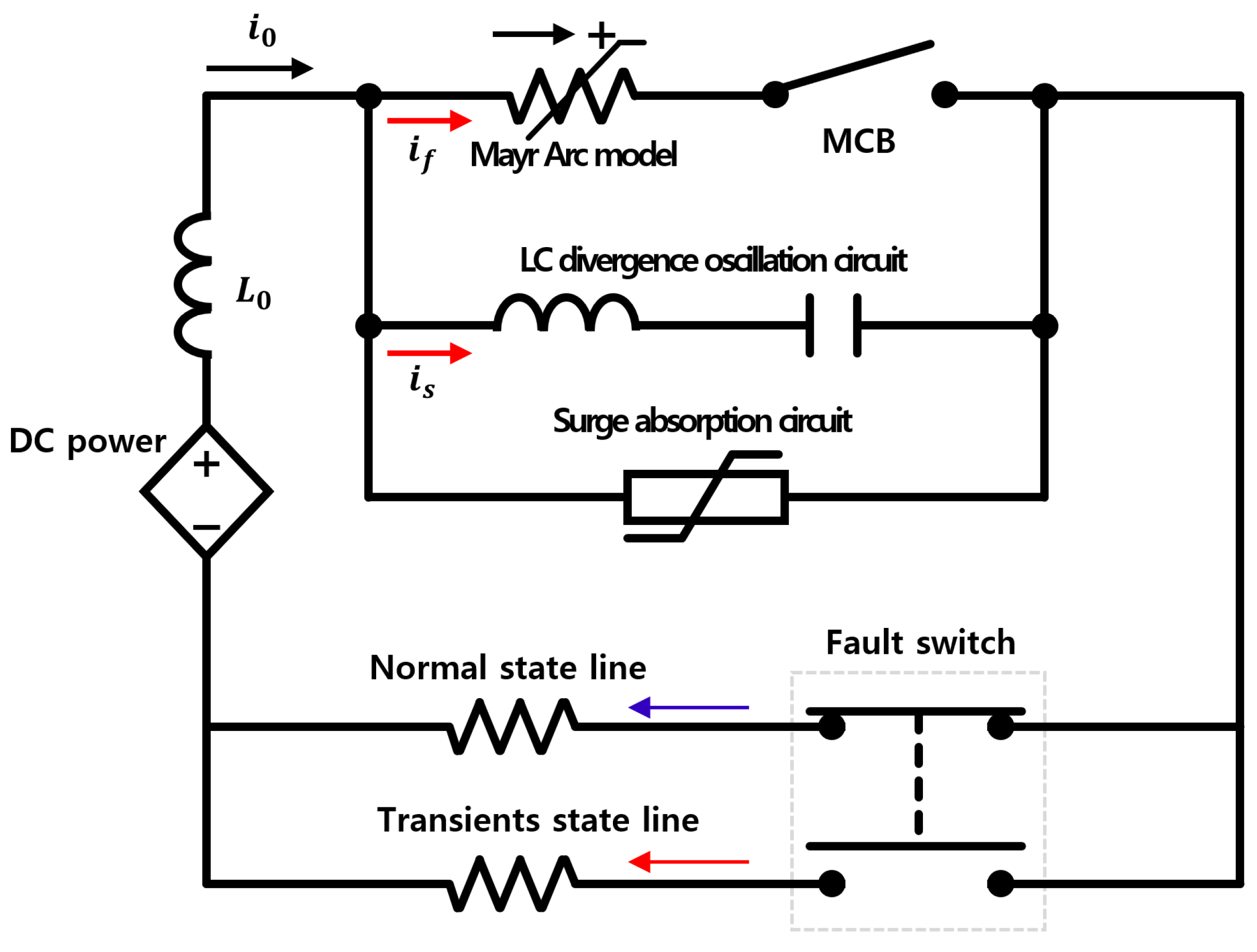
Figure 1 is a simulation circuit diagram of a mechanical DC circuit breaker applied with the LC divergence oscillation method. It consists of DC power, line impedance (), and mechanical DC circuit breaker. The mechanical DC circuit breaker is composed of the Mayr arc model, mechanical DC switch, LC divergence oscillation circuit, and a surge absorption circuit connected in parallel. The fault switch determines the normal line and the faulty line.
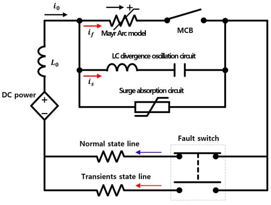
Figure 1.
Simulation circuit structure of mechanical DC circuit breaker applying LC divergence oscillation method.
In the normal state, the normal current flows through the mechanical circuit breaker (MCB) to the load.
In a transient state, the contact is opened and the fault line is separated when a fault current occurs. The LC divergence oscillation circuit is a circuit in which a capacitor (C) and a reactor (L) are coupled in series. This generates an oscillating current in the event of an accident, induces a fault current to the zero-point, and assists in the opening operation of the MCB. Finally, a zinc oxide (ZnO) arrester is applied to the absorption circuit. It flows the current remaining across the LC divergence oscillation circuit to the ground. The MCB performs an opening operation when an accident occurs in a line. At this time, the internal impedance is increased by the arc reverse characteristics generated and the fault current is commutated to the LC divergence oscillation circuit. At the same time, the oscillation current has an effect on the fault current of the MCB by the reactor and capacitor applied to the oscillation circuit. This amplitude gradually increases and reaches the current to the zero-point. A fault current of the MCB is created at zero-point at the moment when the magnitude of the divergence oscillation current flowing in the LC circuit exceeds the magnitude of the fault current in the main MCB circuit. At this moment, the MCB is fully opened. As a result, the magnitude of the voltage and current generated across the circuit breaker is reduced and the residual voltage and current flow through the ground with ZnO applied to the surge absorption circuit, completing the cut-off operation [24,25,26]. It can be described as Equations (1) and (2) using Kirchhoff’s current and voltage law in the circuit diagram of Figure 1. is the total current flowing in the mainline and is the fault current flowing in the MCB line. is the current flowing through the LC divergence oscillation circuit. L and C are reactors and capacitors composed of LC divergence oscillation circuits. is the arc voltage appearing at the MCB. Therefore, the current flowing in the mainline can be described as Equation (3). The condition for making the vibration current of the LC divergent oscillation circuit is that the angle of the arc voltage in Equation (4) with respect to the rising current in Equation (3) should be the minus value. Also, as the magnitude of the absolute value of Equation (4) increases, the MCB operates faster [26].
where,
- : Current of the main line
- : Fault current in the MCB line
- : Current in the LC divergence oscillation circuit
- : Inductance of the LC divergence oscillation circuit
- C: Capacitance of the LC divergence oscillation circuit
- : Arc voltage
Figure 1 shows the diagram of a PSCAD/EMTDC simulation circuit. MCB was a mechanical DC cut-off switch and LS’ Susol TD100N cut-off switch is a model. We applied some parameters, speed of the cut-off operation, and characteristics, through the experiment to the simulation model. The LC circuit was a divergence oscillation type circuit and the reactor are set at about 15 and the capacitor at about 250 . The absorbing circuit was an arrester and is set to 570 V. This is because the surge arrester operating voltage is set to be 15~25% higher than the used and rated voltage. With a DC simulation system, the rated voltage is 500 V, the rated current is 43 A and the fault current occurred up to about 464 A. In particular, the arc which is the switching surge caused by the fault current had to be implemented as a simulation model. We chose the Mayr model (5) for the arc model. The reason is that the Mayr arc equation represents the arc generated when a small current, near-zero current is cut off. In addition, it is because the Mayr arc equation is used at a plasma temperature of 8000 K or less. is the arc conductance and is the arc time constant. is the arc voltage and is the arc current. is the cooling power constant [26,27,28,29].
2.2. Simulation Design and Results
- gc: The arc conductance
- τtc: The arc time constant
- uarc: The arc voltage
- iarc: The arc current
- P0: The cooling power constant
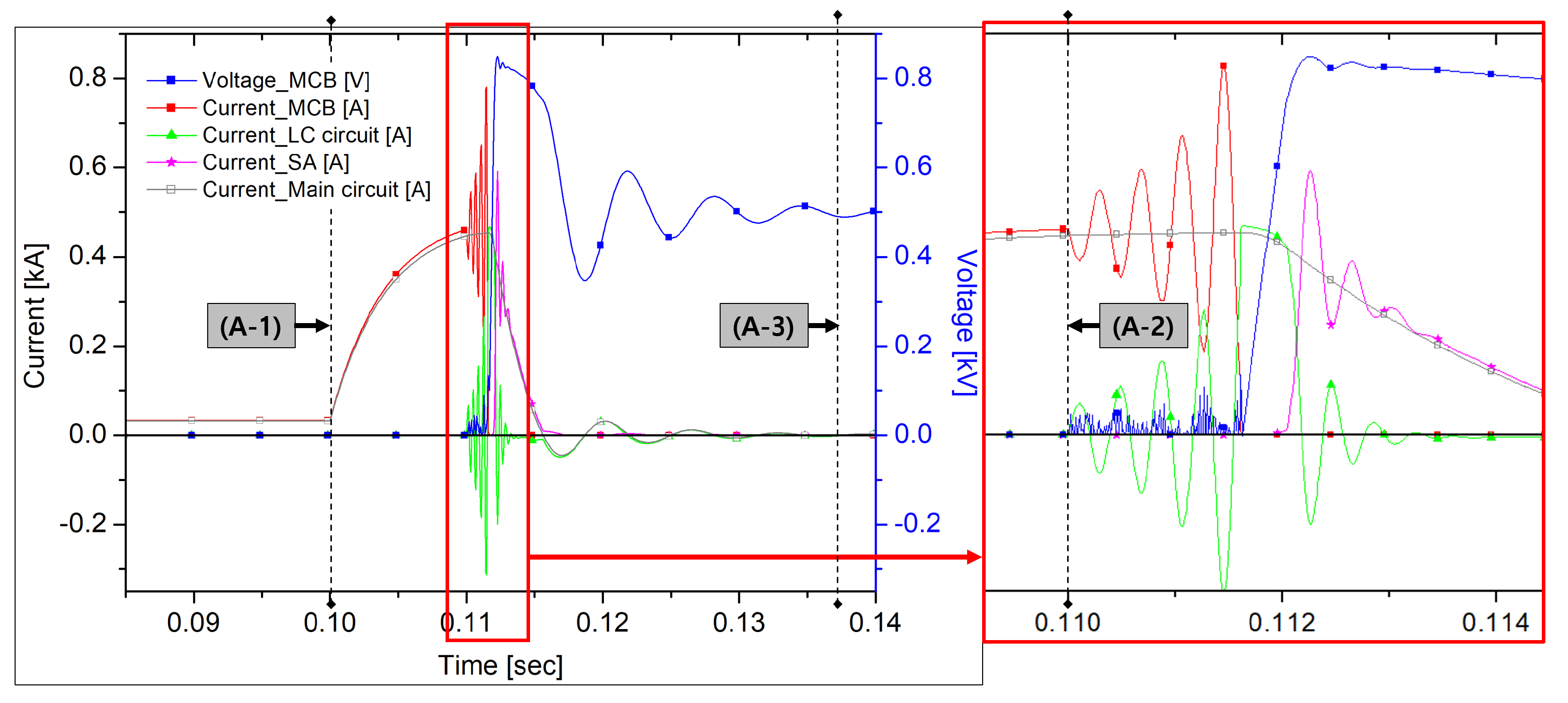
Figure 2 is a graph of the operating characteristics of a DC circuit breaker to which the divergence oscillation method is applied through the simulation program. Figure 2 (A-1) is the time the accident has started. Figure 2 (A-2) is the time when the MCB’s open operation occurs. Figure 2 (A-3) is the point at which the accident has completely ended. As a result of the simulation, an accident occurred in about 0.11 s. At this moment, the normal current was about 43 A before the cut-off switch started to open in the MCB. The opening operation of the MCB was started and an arc voltage of about 50 V was generated. In the LC divergence oscillation circuit, as shown in the graph, it caused oscillation and affected the fault current in the MCB. The fault current gradually increased in amplitude and reached the zero point and the cutting-off of the MCB was completed in about 0.116 s. From the moment the MCB was disconnected, all fault currents flowed through the divergence oscillation circuit. The opening operation of the MCB was completed and the voltage started to rise. When the voltage reached about 570 V, the operation of the surge arrester started. At this time, about 0.112 s, the fault current was extinguished through the surge arrester. At the moment the lightning arrester was operated, oscillation was generated in the diverging oscillation circuit. Finally, all fault currents were extinguished at about 0.137 s. The time taken to cut-off was about 0.037 s.
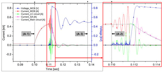
Figure 2.
Graphs of the operating characteristic of the DC circuit breaker to which divergence oscillation method is applied in the simulation.
3. Experiment
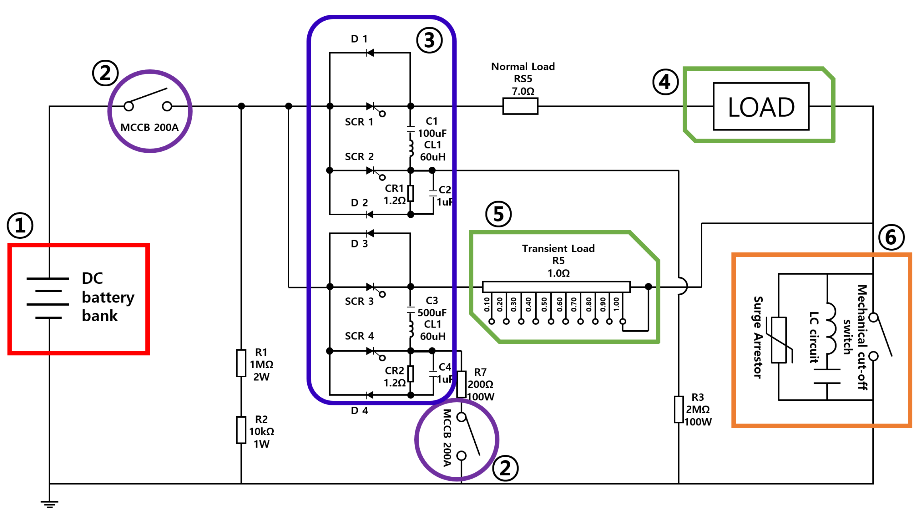
Figure 3 is the circuit diagram of the simulation accident generator in the DC system. (1) is a DC power supply about 150 AH–12 V lead-acid batteries are connected in series. (2) is the main circuit breaker of the simulated accident generating device and protects the circuit from electrical accidents other than the corresponding experiment. (3) is a line changeover switch composed of a thyristor SCR (Silicon controlled rectifier), which is a power semiconductor. It can switch each normal line and transient line through the fast switching. (4) is the load of the normal line. (5) is the load of the transient line. (6) is the position of the model to be tested and the DC circuit breaker to which the divergence oscillation method is applied.
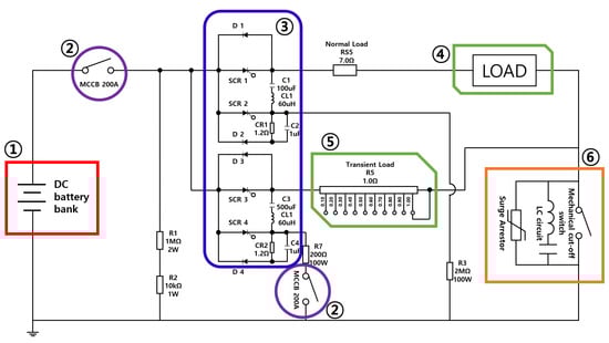
Figure 3.
Circuit diagram of simulated accident generator in DC system.
This simulated accident generator can set the accident time arbitrarily by the user and can generate a fault current of up to 800 A. In this paper, the rated voltage and current of about 500 V and 35 A were set. The normal load was set to about 15 Ω and the transient load to about 1 Ω.
The mechanical cut-off switch of the DC circuit breaker used Susol’s TD100N model and the set values according to each variable were applied to the Reactor and Capacitor. The surge arrestor model was SUP2H1 and about 470 V was used. This is an experiment on the variables of Reactor and Capacitor. The purpose of this experiment is to compare and analyze the cut-off operation characteristics that occur under various conditions.
3.1. Design of the Reactor Variable
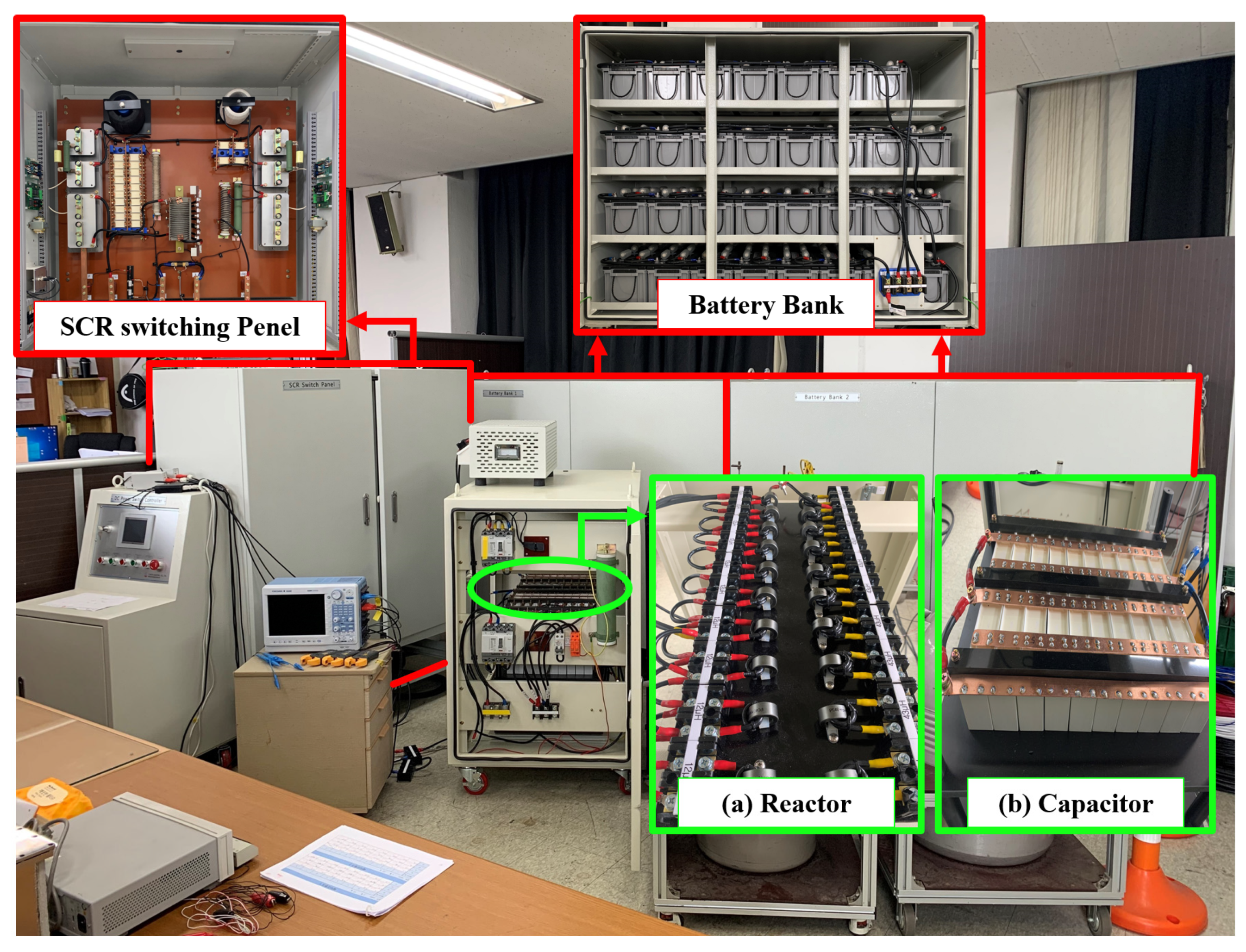
Figure 4 shows the testbed (SCR switching panel, Battery bank, etc.) in the lab with the reactor and capacitor used in the experiment. Figure 4a shows the reactor applied to the experiment of operating characteristics according to the reactance variable. About 12 and about 43 reactors were made, 10 each. We conducted experiments using about 5, 15, and 25 reactors. The capacitor in Figure 4b was fixed at about 750 . The resonance frequencies were 2599, 1500, and 1162 Hz, respectively, according to the change in the reactor as follows [29].

Figure 4.
Test bed in the lab with the LC divergence oscillation circuit configured in Reactor and Capacitor.
3.2. Results of the Reactor Variable
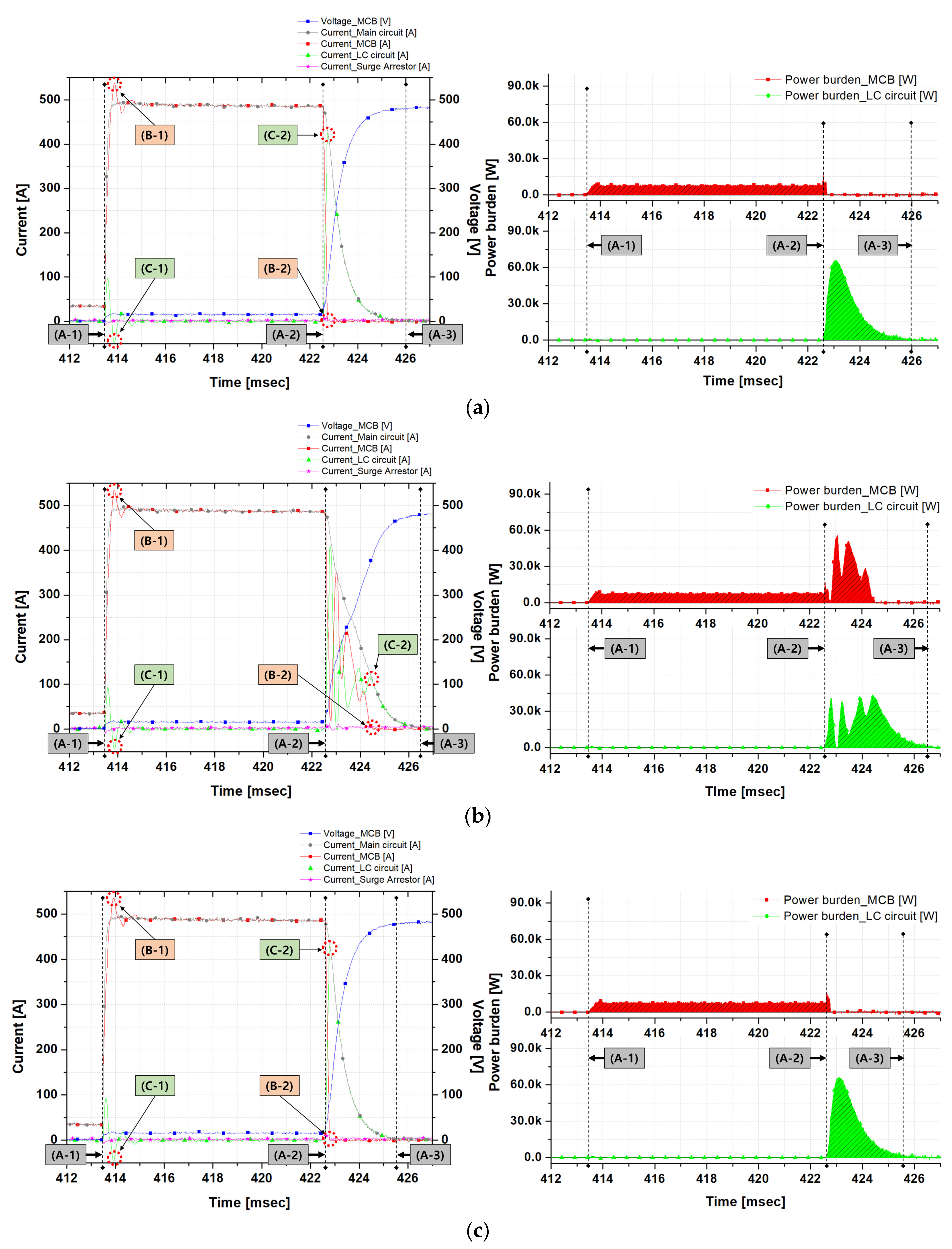
Figure 5 is a graph of the cut-off operation characteristics applied to the DC circuit breaker with Reactor variables. In the graph, Voltage_MCB (V) refers to the voltage generated at the MCB. Current_Main circuit (A) refers to the initial current flowing into the DC circuit breaker. It is equal to the sum of Current_MCB (A), Current_LC circuit (A), and Current_Surge arrestor (A) according to Kirchhoff’s first law. However, this holds only under the condition that heat energy and light energy emitted and consumed are ignored in the process of cut-off operation of the MCB. Current_MCB (A) refers to the current flowing through the MCB. Current_LC circuit (A) refers to the current flowing through the LC divergence oscillation circuit. Current_surge arrestor (A) refers to the current flowing through the arrester.
Current_Main (A) = Current_MCB (A) + Current_LC circuit (A) + Current_Surge arrestor (A)
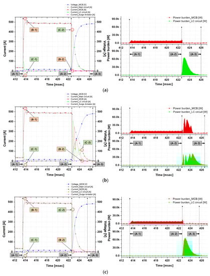
Figure 5.
Operational characteristics analysis graph of DC circuit breaker to which the Reactor variable is applied (a) 5 , (b) 15 , (c) 25 .
In the graph, there are indicators for each time point A, B, and C. A is the reference point, B is the fault current flowing through the MCB and C is the fault current flowing through the LC divergence oscillation circuit. In more detail, (A-1) is the time when the fault occurred, and (A-2) is the time when the mechanical cut-off switch started to open. (A-3) is the time when the cut-off is completed. (B-1) is the point at which the maximum value of the initial fault current occurred in the MCB. (B-2) is the point when the fault current flowing through the MCB reaches the zero-point. (C-1) is the fault current of the LC divergence oscillation circuit generated when the maximum value of the initial fault current flowing through the MCB occurs. (C-2) is the fault current of the LC divergence oscillation circuit generated when the fault current flowing through the MCB reaches to the zero-point. The time of occurrence of all experiments is about 413.4 ms.
As a result, the following results were confirmed. The experimental results are summarized in Table 1.

Table 1.
Experimental result table of operating characteristics of DC circuit breaker to which the Capacitor variable are applied.
The standards were set as follows.
- -
- Time of occurrence of an accident
- -
- Maximum value of the initial fault current
- -
- Time when the DC cut-off switch was opened
- -
- Time when the MCB fault current reached the zero point
- -
- Time when the accident cutoff was completed
- -
- Power burden
When a reactor 5 and a capacitor 750 were applied, the accident occurred at about 413.4 ms. The normal current was about 39.2 A. The initial fault current was about 540.6 A at about 413.8 ms. The opening operation of the MCB occurred at about 422.5 ms and the fault current was about 480.4 A. LC divergence oscillation according to MCB opening operation did not occur. Therefore, a situation occurred where the fault current all flowed to the LC divergence oscillation circuit according to the MCB’s open operation. It took about 0.5 ms. The power burden due to the fault current of the MCB and LC circuits was 2608 W and 74,949 W, respectively and the LC circuit received a lot of power burden. The power burden was calculated from the time of MCB open operation to the time of accident completion. Finally, the fault current cut-off time was about 12.0 ms.
When reactor 15 and capacitor 750 were applied, the accident occurred at about 413.4 ms. The steady current was about 37.8 A. The initial fault current was about 536.0 A at about 413.8 ms. The opening operation of the MCB occurred at about 422.5 ms and the fault current was about 483.4 A. LC divergence oscillation occurred according to MCB opening operation. Therefore, the fault current of the MCB and the fault current flowing through the LC divergence oscillation circuit vibrated with the same amplitude. By this oscillation, the time to reach the zero point of the fault current of the MCB was increased by about 1.9 ms. The power burden due to the fault current of the MCB and LC circuits was 53,180 W and 75,928 W, respectively. The MCB and LC circuits shared each other’s power burden by a certain ratio. Finally, the fault current cut-off time was about 13.1 ms.
When Reactor 25 and Capacitor 750 were applied, the accident occurred at about 413.4 ms. The steady current was about 37.8 A. The initial fault current was about 535.2 A at about 413.8 ms. The opening operation of the MCB occurred at about 422.6 ms and the fault current was about 484.7 A. LC divergence oscillation according to MCB opening operation did not occur. Therefore, the power burden caused by the fault current of the MCB and LC circuits was 1870 W and 75,407 W, respectively and the LC circuit received considerable power burden. Finally, the fault current cut-off time was about 12.2 ms.
3.3. Design of the Capacitor Variable
Figure 4b shows the capacitor applied to the experiment of operating characteristics according to the capacitance variable. A model of each variable was made by connecting about 25 non-polar capacitors in series. We conducted experiments using about 250, 500, 750, 1000, and 1250 capacitors. The reactor in Figure 4a was fixed at about 15 . The resonance frequencies were 2598, 1837, 1500, 1299, and 1162 Hz, respectively, according to the change in capacitance as follows.
3.4. Results of the Capacitor Variable
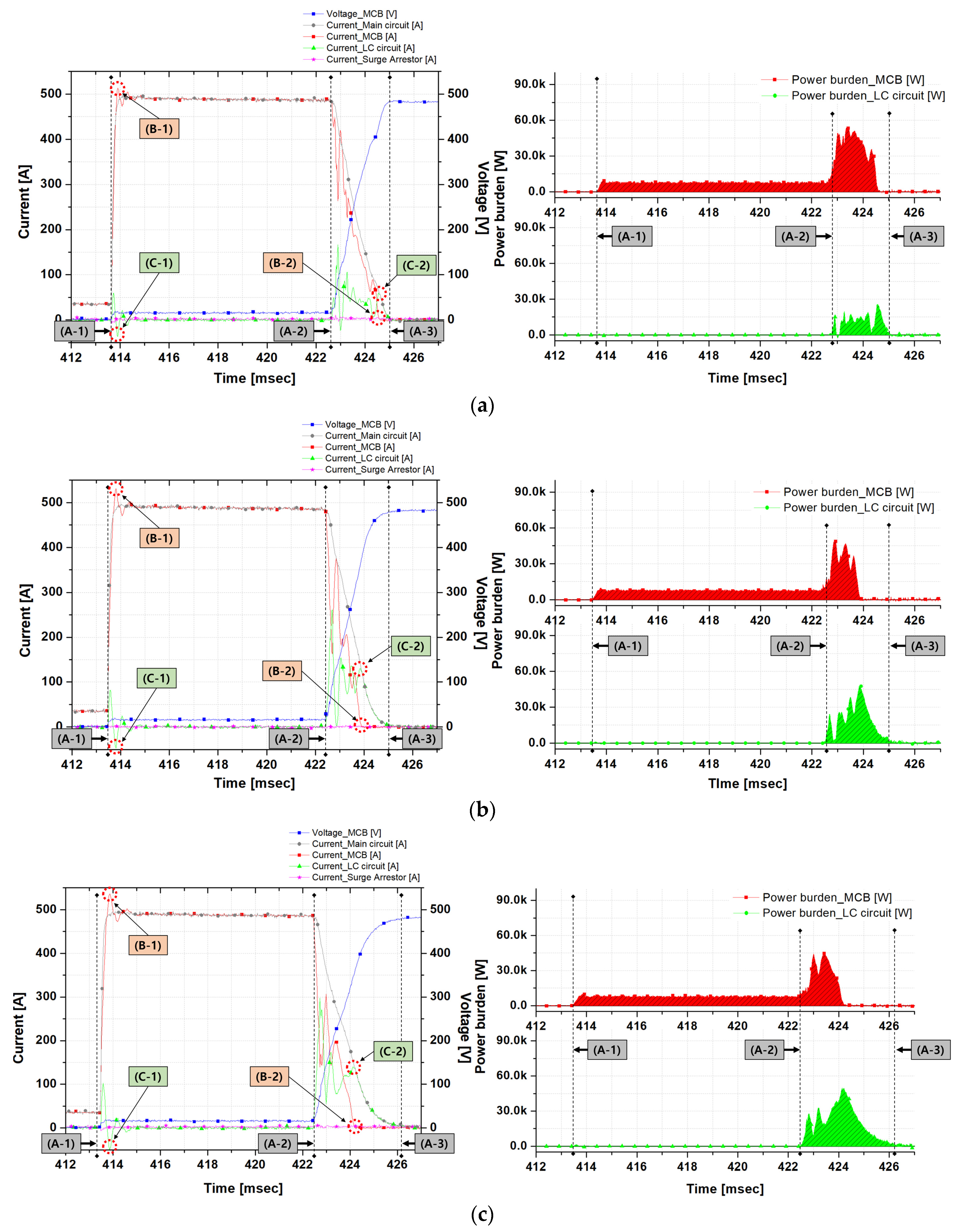
Figure 6 is a graph of operating characteristics of the cut-off in which the capacitance parameter is applied to the DC circuit breaker. The results are summarized in Figure 6 and Table 2.
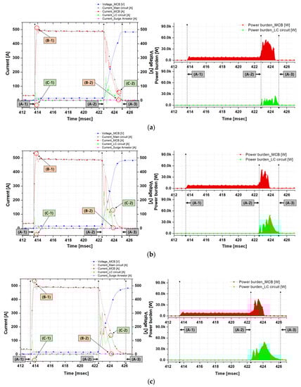
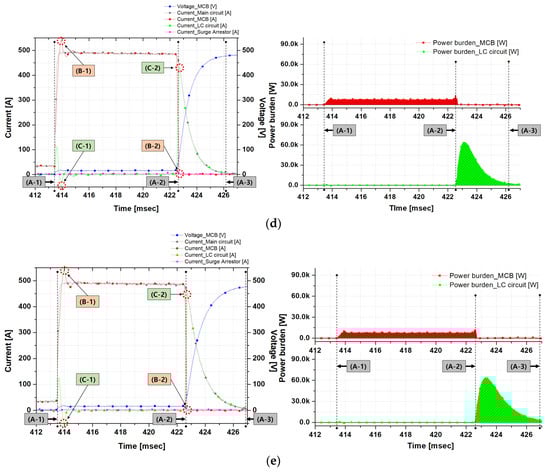
Figure 6.
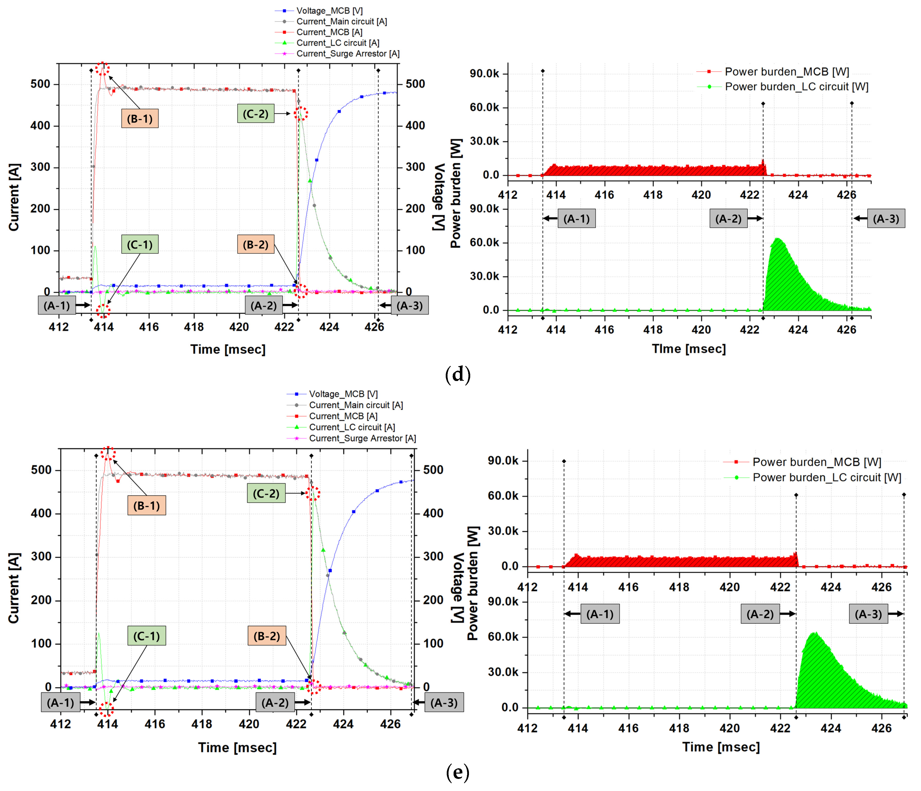
Operation characteristics analysis of the DC circuit breaker to which the capacitor variable is applied (a) 250 , (b) 500 , (c) 750 , (d) 1000 , (e) 1250 .
Table 2.
E Experimental result table of the operating characteristics of the DC circuit breaker to which the Capacitor variables are applied.
When the capacitor 250 and reactor 15 were applied, the fault occurred in about 413.4 ms. A normal current of about 35.5 A was generated. The initial fault current ranged from about 413.9 ms to about 515.2 A. The opening operation of the MCB occurred at about 422.6 ms and the fault current was about 485.4 A. LC divergence oscillation occurred in response to the MCB opening operation. Therefore, the fault current of the MCB and the fault current flowing through the LC divergence oscillation circuit vibrated with the same amplitude. It took about 2.0 ms for this oscillation to reach zero fault current in the MCB. The power burden due to the fault current of the MCB and LC circuits was 70,573 W and 25,477 W, respectively. The MCB and LC circuits shared the power burden of each other in a certain ratio (7.4:2.6). Ultimately, the fault current cutoff time was approximately 11.6 ms.
When the capacitor 500 and reactor 15 were applied, the fault occurred in about 413.4 ms. A normal current of about 34.7 A was generated. The initial fault current ranged from about 413.9 ms to about 532.9 A. The opening operation of the MCB occurred at about 422.4 ms and the fault current was about 485.6 A. LC divergence oscillation occurred in response to the MCB opening operation. This oscillation took about 1.5 ms to reach zero fault current in the MCB. The power burden due to the fault current of the MCB and LC circuits was 42,980 W and 50,913 W, respectively. The MCB and LC circuits shared the power burden of each other in a certain ratio (4.5: 5.4). Ultimately, the fault current cutoff time was approximately 11.5 ms.
When the capacitor 750 and reactor 15 were applied, the fault occurred in about 413.4 ms. A normal current of about 37.8 A was generated. The initial fault current ranged from about 413.8 ms to about 535.7 A. The opening operation of the MCB occurred in about 422.5 ms and the fault current was about 481.8 A. LC divergence oscillation occurred in response to the MCB opening operation. It took about 1.9 ms for this oscillation to reach zero fault current in the MCB. The power burden due to the fault current of the MCB and LC circuits was 45,659 W and 76,006 W, respectively. The MCB and LC circuits shared the power burden of each other in a certain ratio (3.8:6.2). Finally, the fault current cutoff time was about 13.0 ms.
When the capacitor 1000 and reactor 15 were applied, the fault occurred in about 413.4 ms. A normal current of about 34.7 A was generated. The initial fault current ranged from about 413.9 ms to about 539.7 A. The opening operation of the MCB occurred at about 422.4 ms and the fault current was about 486.3 A. LC divergence oscillation did not occur in response to the MCB opening operation. Therefore, from this time, the fault current flowed through the LC divergence oscillation circuits. The time took about 0.3 ms. The power burden due to the fault current of the MCB and LC circuit was 2684 W and 100,821 W, respectively, while the LC circuit received a large power burden. Finally, the fault current cutoff time was about 13.1 ms.
When the capacitor 1250 and reactor 15 were applied, the fault occurred in about 413.4 ms. A normal current of about 36.2 A was generated. The initial fault current ranged from about 413.9 ms to about 542.8 A. The opening operation of the MCB occurred in about 422.5 ms and the fault current was about 482.1 A. LC divergence oscillation did not occur in response to the MCB opening operation. Therefore, from this time, the fault current flowed through the LC divergence oscillation circuits. The time took about 0.2 ms. The power burden due to the fault current of the MCB and LC circuit was 1744 W and 125,501 W, respectively, while the LC circuit received a large power burden. Finally, the fault current cutoff time was about 13.8 ms.
4. Review
Figure 2 and Figure 6a are graphs showing the operating characteristics of the mechanical DC circuit breaker through each simulation and experiment. The operation characteristics of the mechanical DC switch were applied to the simulation in the values confirmed based on the experiment and were shown as a graph in Figure 2. However, there are three errors. The first is in the arc energy generated when the opening operation of the MCB is carried out. In the simulation, the arc occurs from about 0.11 s (A-2). Arc energy starts to decrease after in Equation (1) occurs after the artificial zero-point of . It means that is not consumed until becomes 0. This may be attributed to the non-application of the light energy and heat energy of the arc in the simulation. Second, it involves the operating voltage of the surge arrestor. This simulation is an ideal model to explain the operating theory and characteristics of the mechanical DC circuit breaker. Therefore, the operation voltage of the surge arrestor had to be set 15~25% higher than the applied voltage. The maximum operating voltage set in the simulation is about 625 V. However since the minimum operating voltage in an actual surge arrestor is 1000 V, there is such an error. Third, the operation characteristics of the mechanical DC switch used in this paper are a thermal type and have a driving method using bimetal. The time required for this is about 9 ms. This feature was not applied to the simulation. This operation characteristic is omitted because it is unnecessary to explain the operation characteristic of the mechanical DC circuit breaker.
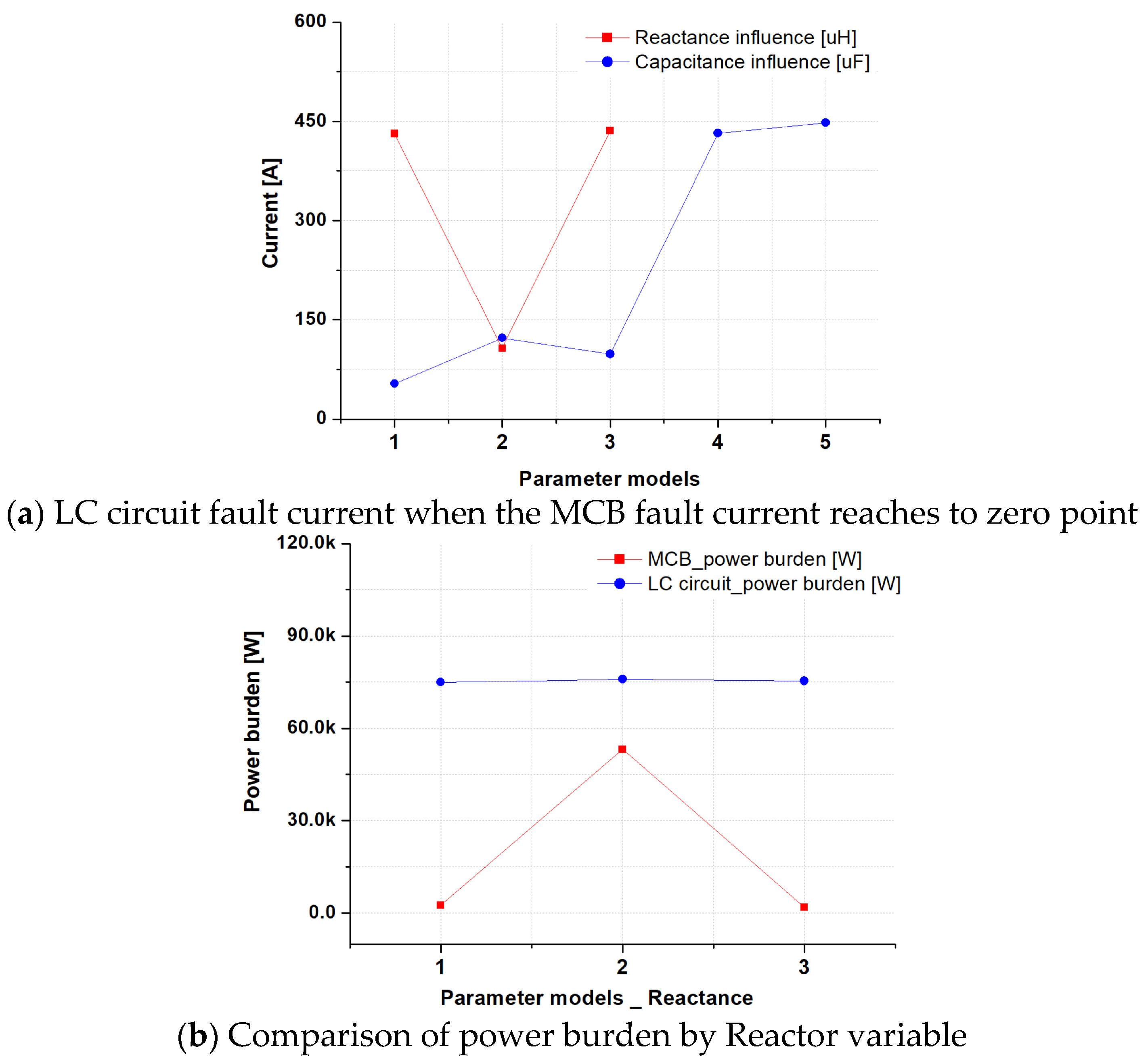
Figure 7 is a graph in which the operating characteristics of the DC circuit breaker are analyzed based on several criteria. The Parameter model has 3 cases with reactor variables and 5 cases with capacitor variables. In the first experiment, the reactor variable experiment, the reactance variables were (1) 5 , (2) 15 , (3) 25 and the fixed capacitance was 750 . In the second experiment, the experiment of the variable of capacitance, the capacities were (1) 250 , (2) 500 , (3) 750 , (4) 1000 , (5) 1250 , and the fixed reactance was 15 .
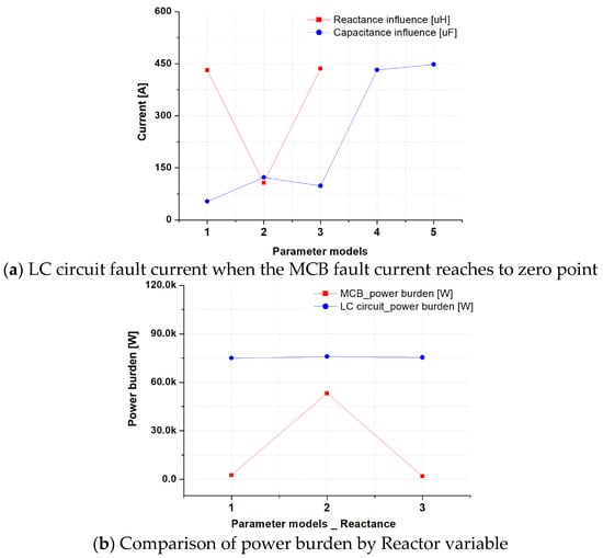
Figure 7.
Comparison of operating characteristics for each standard.
Figure 7a illustrates the fault current that flows through the LC circuit when the fault current that flows through the MCB reaches an artificial zero-point (C-2). Results it was confirmed that when the fault current resonates and oscillation is generated, a low fault current of about 0 to 150 A flows in the LC circuit. In the absence of oscillation, it was confirmed that a high fault current of about 450 A flows in the LC circuit.
Figure 7b is a graph comparing the power burden of the MCB and LC circuits generated in the experimental results using the Reactor variables. We confirmed the result that the MCB and LC circuit evenly share the power burden when oscillation is generated due to the resonance of the fault current. The power burden was calculated through Equation (7).
where,
- (A-1): The time of point at which the accident has started.
- (A-3): The time of point at which the accident has completely ended.
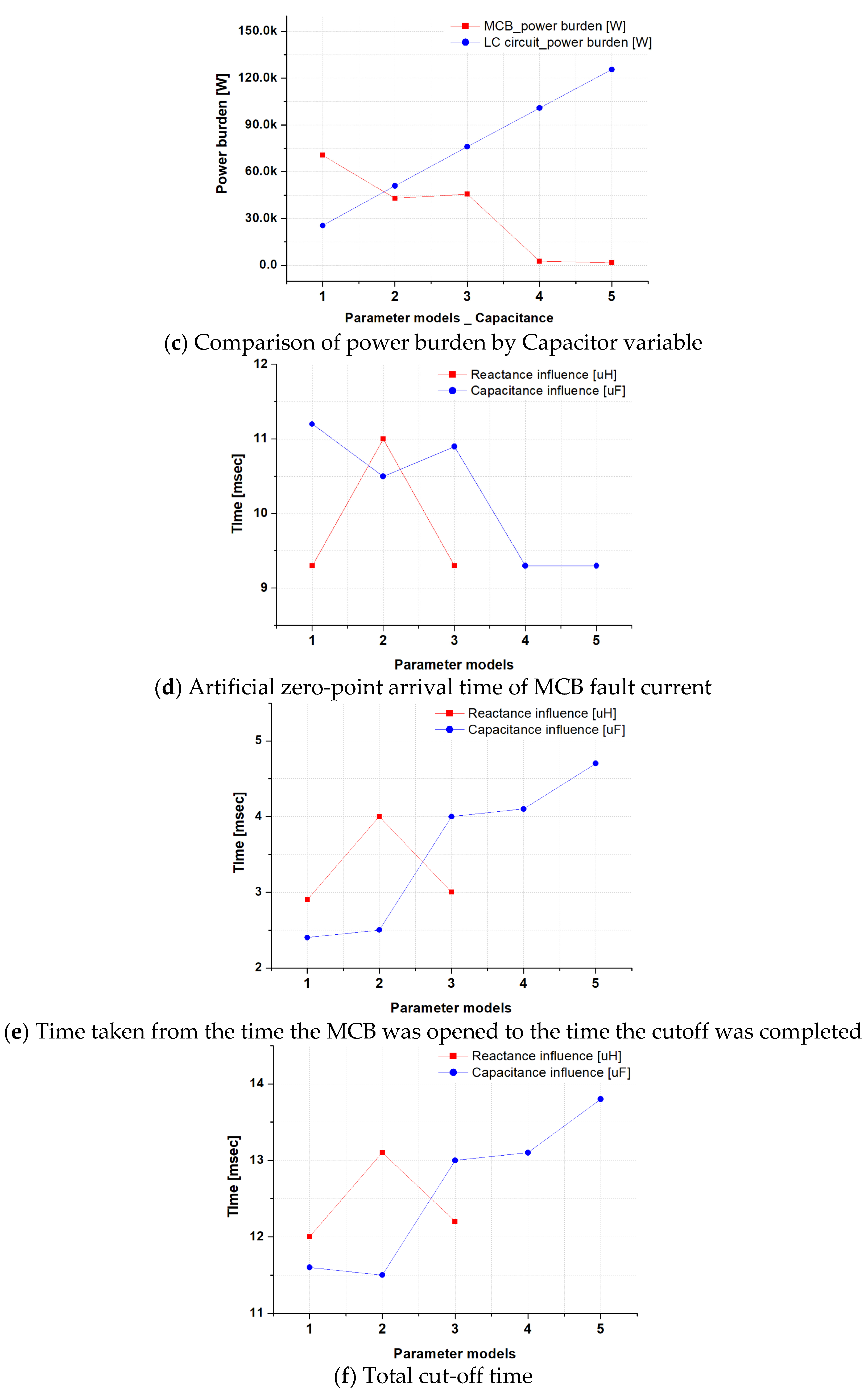
Figure 7c is a graph comparing the power burden of the MCB and LC circuits generated in the experimental results using the Capacitor variables. For 1 to 3 times, the fault current oscillation was generated, but the 4th and 5th oscillations were not generated. The oscillation of the fault current makes the MCB and the LC circuit share the power burden.
Figure 7d illustrates the time it takes for the fault current flowing from the MCB to reach artificial zero (B-2). In this experimental result, the time difference was certain depending on the presence or absence of oscillation of the fault current. When the opening operation of the MCB was started and oscillation occurred in the LC circuit, an artificial zero occurred between about 10.5 and 11.5 ms. When the LC circuit did not vibrate, an artificial zero-point occurred between about 9 and 9.5 ms.
Figure 7e shows the time taken from the opening operation of the MCB (B-2) to the completion of the cut-off (A-3). From the result of the reactance influence, the cut-off time was increased by about 1 ms according to the oscillation of the fault current. From the result of Capacitance influence, it can be seen that the oscillation of the fault current is generated and the smaller the power load of the LC circuit is, the shorter the interruption time becomes. Therefore, we increase the cutoff time that causes the fault current to oscillate through the resonance of the LC circuit. However, it can be seen that the time is shortened as the capacitance becomes smaller.
Figure 7f shows the total cutoff time in a graph. As a result of the reactor influence, the total cut-off time was increased by about 1 ms as the oscillation of the fault current occurred. From the result of Capacitance influence, it can be seen that the oscillation of the fault current is generated and the smaller the power load of the LC circuit is, the shorter the interruption time becomes. It was found that the total cutoff time is determined by the time from the time when the MCB is opened to the time when the cutoff is completed. The total cutoff time was calculated through Equation (7).
Total cutoff time (msec) = (A-3) – (A-1)
5. Conclusions
The LC divergence oscillation circuit is a method that can resolve the damage and shortening of the life of the contact of the mechanical DC circuit breaker due to the occurrence of a strong Arc plasma in the MCB. In addition, it is possible to prevent a second accident from a strong Arc plasma. The biggest advantage of the LC divergence oscillation method is that the LC divergence oscillation circuit shares the power burden of the MCB through the artificial-current zero-point of the MCB and also helps maintain a stable cutoff operation. Therefore, we analyzed the cutoff operation characteristics of the mechanical DC circuit breaker applying the LC divergence oscillation method through simulations and experiments. In this paper, the values corresponding to the elements of the LC divergence oscillation circuit were designed with reference to previous studies and were applied to the simulation model. First, the characteristics of the LC divergence oscillation circuit generated in the simulation were checked, and based on that a mechanical DC circuit breaker experiment equipment with an LC divergence oscillation circuit was designed. Second, we prepared a system that simulated the DC system required for the experiment. We also prepared a DC circuit breaker model to which the LC divergence oscillation circuit was applied. The reactor variable was set in the first experiment and the capacitance variable was set in the second experiment. Here, a variable for displaying the operating characteristics according to the presence or absence of resonance was set together. The results can be summarized as follows.
- -
- Since the LC divergence oscillation is generated after the opening operation of the MCB, the total block speed depends on the opening operation speed of the MCB.
- -
- The cutoff time increases as the capacity of the reactor and capacitor increases.
- -
- The ratio of the power burden generated in the MCB and LC circuit is determined according to the presence or absence of LC resonance.
- -
- The slope of the arc voltage of Equation (4) for the rising fault current of Equation (3) must have a minus (−) value.
We compared and analyzed the operating characteristics of the mechanical DC circuit breaker caused by the parameters of the LC divergence oscillation circuit. We plan to continue research on the DC circuit breaker model proposed in this paper to facilitate high-reliability cutoff operation through conditions of the power system in various environments.
Author Contributions
Conceptualization, S.-Y.P.; Data curation, S.-Y.P.; Formal analysis, S.-Y.P.; Funding acquisition, H.-S.C.; Investigation, S.-Y.P.; Methodology, S.-Y.P.; Project administration, H.-S.C.; Resources, S.-Y.P.; Software, S.-Y.P.; Supervision, H.-S.C.; Validation, H.-S.C.; Visualization, S.-Y.P.; Writing—original draft, S.-Y.P.; Writing—review & editing, H.-S.C. All authors have read and agreed to the published version of the manuscript.
Funding
This research received no external funding.
Institutional Review Board Statement
Not applicable.
Informed Consent Statement
Not applicable.
Data Availability Statement
Not applicable.
Acknowledgments
This research was supported by Korea Electric Power corporation [grant number: R21XO01-32].
Conflicts of Interest
The authors declare no conflict of interest.
References
- Lazdins, R.; Mutule, A.; Zalostiba, D. PV Energy Communities—Challenges and Barriers from a Consumer Perspective: A Literature Review. Energies 2021, 14, 4873. [Google Scholar] [CrossRef]
- Lucas, H.; Carbajo, R.; Machiba, T.; Zhukov, E.; Cabeza, L. Improving Public Attitude towards Renewable Energy. Energies 2021, 14, 4521. [Google Scholar] [CrossRef]
- Kolosok, S.; Bilan, Y.; Vasylieva, T.; Wojciechowski, A.; Morawski, M. A Scoping Review of Renewable Energy, Sustainability and the Environment. Energies 2021, 14, 4490. [Google Scholar] [CrossRef]
- Li, H.; Xiang, B.; Song, W.; Geng, Y.; Liu, Z.; Wang, J.; Pei, X.; Tu, Y. Effect of arc chute on DC current interruption by liquid nitrogen in HTS electrical system of distributed propilsion aircraft. IEEE Trans. Appl. Supercond. 2021, 31, 5601305. [Google Scholar] [CrossRef]
- Raza, A.; Mustafa, A.; Alqasemi, U.; Rouzbehi, K.; Muzzammel, R.; Guobing, S.; Abbas, G. HVdc Circuit Breakers: Prospects and Challenges. Appl. Sci. 2021, 11, 5047. [Google Scholar] [CrossRef]
- Ha’fner, J.; Jacobson, B. Proactive hybrid HVDC breakers—A key innovation for reliable HVDC grids. In Proceedings of the Electric Power System of the Future-Integrating Supergrids and Microgrids International Symposium, Bologna, Italy, 13–15 September 2011. [Google Scholar]
- Choi HWPark, S.Y.; Choi, H.S. Characteristics of a current-limiting DC circuit breaker with a superconducting coil applied to the commutation circuit. J. Electr. Eng. Technol. 2020, 15, 1921–1926. [Google Scholar] [CrossRef]
- Barnes, M.; Vilchis-rodriguez, D.S.; Pei, X.; Shuttleworth, R.; Cwikowski, O.; Smith, A.C. HVDC circuit breaker-A review. IEEE Access 2020, 8, 211829–211848. [Google Scholar] [CrossRef]
- Novák, B. Arc motion between the splitter plates of a medium-voltage SF6-insulated load break switch. IEEE Trans. Appl. Supercond. 2019, 9, 1354–1361. [Google Scholar] [CrossRef]
- Mohammadi, F.; Nazri, G.-A.; Saif, M. A New Topology of a Fast Proactive Hybrid DC Circuit Breaker for MT-HVDC Grids. Sustainability 2019, 11, 4493. [Google Scholar] [CrossRef] [Green Version]
- Choi, H.W.; Jeong, I.S.; Park, S.Y.; Choi, H.S. Characteristics of superconducting coil-type DC fault current limiter to increase stability in the grid connection PV generation system. IEEE Trans. App. Supercond. 2018, 28, 5600904. [Google Scholar] [CrossRef]
- Mokhberboran, A.; Carvalho, A.; Leite, H.; Silva, N. A review on HVDC circuit breakers. In Proceedings of the 3rd Renewable Power Generation Conference (RPG 2014), Naples, Italy, 24–25 September 2014; IET: Stevenage, UK, 2015. [Google Scholar]
- Javed, W.; Chen, D.; Farrag, M.E.; Xu, Y. System Configuration, Fault Detection, Location, Isolation and Restoration: A Review on LVDC Microgrid Protections. Energies 2019, 12, 1001. [Google Scholar] [CrossRef] [Green Version]
- Joo, N.K. Study on the Development of DC Circuit Breaker. Doctoral Thesis, Kangwon University in Korea, Chuncheon, Korea, 2014. [Google Scholar]
- Tamura, S.; Shimada, R.; Kito, Y.; Kanai, Y.; Koike, H.; Ikeda, H.; Yanabu, S. Parallel Interruption of Heavy Direct Current by Vacuum Circuit Breakers. IEEE Trans. Power Appar. Syst. 1980, PASS-99, 1119–1129. [Google Scholar] [CrossRef]
- Lee, Y.S.; Kim, J.H.; Han, B.M.; Lee, J.Y. Auxiliary resonant commutated pole inverter with clamping diodes for voltage stress reduction across auxiliary switches. In Proceedings of the 2018 IEEE Region 10 Conference, Jeju, Korea, 28–31 October 2018. [Google Scholar]
- Kim, B.C.; Chung, Y.H.; Hwang, H.D.; Mok, H.S. Development of HVDC circuit breaker with fast interruption speed. In Proceedings of the 9th international conference on power electronics-ECCE Asia, Seoul, Korea, 1–5 June 2015. [Google Scholar]
- Tokoyoda, S.; Sato, M.; Kamei, K.; Yoshida, D.; Miyashita, M.; Kikuchi, K.; Ito, H. High frequency interruption characteristics of VCB and its application to high voltage DC circuit breaker. In Proceedings of the 3rd International conference on electric power equipment-switching technology, Busan, Korea, 25–28 October 2015. [Google Scholar]
- Kim, H.S. Gate Drive Controller for Low Voltage DC Hybrid Circuit Breaker. Energies 2021, 14, 1753. [Google Scholar]
- Qu, Y.; Shu, W.; Kang, Y.; Chang, J.S. A 30V 2A Real-Time Programmable Solid-State Circuit Breaker with Improved Detection-Speed and Enhanced Power-Efficiency. In Proceedings of the ESSCIRC 2019–IEEE 45th European Solid State Circuits Conference (ESSCIRC), Cracow, Poland, 23–26 September 2019; Available online: https://ieeexplore.ieee.org/document/8902522 (accessed on 18 November 2019).
- Jamali, S.Z.; Bukhari, S.B.A.; Khan, M.O.; Mehdi, M.; Noh, C.H.; Gwon, G.H.; Kim, C.H. Protection Scheme of a Last Mile Active LVDC Distribution Network with Reclosing Option. Energies 2018, 11, 1093. [Google Scholar] [CrossRef] [Green Version]
- Xiang, B.; Gao, L.; Luo, J.; Wang, C.; Nan, Z.; Liu, Z.; Geng, Y.; Wang, J.; Yanabu, S. A CO2/O2 Mixed Gas DC Circuit Breaker With Superconducting Fault Current-Limiting Technology. IEEE Trans. Power Deliv. 2019, 35, 1960–1967. [Google Scholar] [CrossRef]
- Xiang, B.; Gao, L.; Liu, Z.; Geng, Y.; Wang, J.; Yanabu, S. Study on the parameter requirements for resistive-type superconducting fault currnet limiters combined with mechanical DC circuit breakers in hybrid AC/DC transmission grids. IEEE Trans. Power Del. 2020, 35, 2865–2875. [Google Scholar] [CrossRef]
- ABB. The Hybid HVDC Breaker, An Innovation Breakthrough Enabling in Reliable HVDC Grids. 2012. Available online: https://library.e.abb.com/public/c9d5ba256e7e9671c1257ab6004b1feb/hybrid-hvdc-breake---an-innovation-breakthrough-for-reliable-hvdc-gridsnov2012.pdf (accessed on 18 November 2019).
- Walter, M.M. Switching Arcs in Passive Resonance HVDC Circuit Breakers. Ph.D. Dissertation, Department Power Syst. High Voltage Laboratories, ETH Zurich, Zürich, Switzerland, 2013. [Google Scholar]
- Nakao, H.; Nakagoshi, Y.; Hatano, M.; Koshizuka, T.; Nishiwaki, S.; Kobayashi, A.; Murao, T.; Yanabu, S. DC current interruption in HVDC SF/sub 6/ gas MRTB by means of self-excited oscillation superimposition. IEEE Trans. Power Deliv. 2001, 16, 687–693. [Google Scholar] [CrossRef]
- Ganhao, Z. Study on DC Circuit Breaker. In Proceedings of the 2014 Fifth International Conference on Intelligent Systems Design and Engineering Applications, Baoding, Hebei, China, 15–16 June 2014. [Google Scholar]
- Xiang, B.; Liu, Z.; Geng, Y.; Yanabu, S. DC Circuit Breaker Using Superconductor for Current Limiting. IEEE Trans. Appl. Supercond. 2015, 25, 5600207. [Google Scholar]
- Pei, X.; Smith, A.C.; Barnes, M. Superconducting Fault Current Limiters for HVDC Systems. In Proceedings of the 12th Deep Sea Offshore Wind R&D Conference, Trondheim, Norway, 4–5 February 2015; Volume 80, pp. 47–55. [Google Scholar]
Publisher’s Note: MDPI stays neutral with regard to jurisdictional claims in published maps and institutional affiliations. |
© 2021 by the authors. Licensee MDPI, Basel, Switzerland. This article is an open access article distributed under the terms and conditions of the Creative Commons Attribution (CC BY) license (https://creativecommons.org/licenses/by/4.0/).