Article

Improvement of DC Fault Current Limiting and Interrupting Operation of Hybrid DC Circuit Breaker Using Double Quench

1
Department of Electrical Engineering, Soongsil University, 369 Sangdo-ro, Dongjak-gu, Seoul 156-743, Korea
2
Department of Chemical Engineering, Soongsil University, 369 Sangdo-ro, Dongjak-gu, Seoul 156-743, Korea
3
Department of Mechanical Engineering, Soongsil University, 369 Sangdo-ro, Dongjak-gu, Seoul 156-743, Korea
*
Author to whom correspondence should be addressed.
Energies 2021, 14(14), 4157; https://doi.org/10.3390/en14144157
Submission received: 28 April 2021 / Revised: 30 May 2021 / Accepted: 15 June 2021 / Published: 9 July 2021
(This article belongs to the Special Issue DC Circuit Breaker Technologies State of Art)

Abstract

:
In this paper, direct current (DC) fault current limiting and interrupting operation of hybrid DC circuit breaker (DCCB) using double quench, which consists of DCCB, a series resonance circuit, power electronic switch, surge arrestor, two separated current limiting reactor/resistor, and two superconducting elements, were suggested. The suggested hybrid DCCB can perform the interrupting operation after twice or once DC fault current limiting operation according to DC fault current amplitude. To verify the effective operation of the suggested hybrid DCCB, the modeling for the components of DCCB, the surge arrestor, and the SCE was carried out and its DC operational characteristics were analyzed. Through the analysis of the modeling results for the suggested hybrid DCCB, the advantages of hybrid DCCB were discussed.

1. Introduction

Recently, direct current (DC) grid, called as low voltage DC (LVDC), medium voltage DC (MVDC), or high voltage DC (HVDC) system, has been receiving attention due to the increase of DC load and DC distributed power source and thus the various protection devices for DC grid such as DC circuit breaker (DCCB) have been developed. One of the important technologies in DCCBs is that the increased DC current is to make rapid zero crossings. Another one is to effectively remove the arc in mechanic contact comprising the DCCB. To achieve these technologies in DCCB, the hybrid DCCBs or the modified DCCBs, which utilize the power electronic switches with higher ratings, have been introduced continuously [1,2,3,4,5].
Moreover, the DCCBs, which can achieve the fault current limiting operation shortly before the fault current interruption, have been suggested and the improvement of the DCCB’s performance through the combination of the superconducting elements (SCEs) has been constantly reported [6,7,8,9,10].
In this paper, the hybrid DCCB using double quench of SCEs, which has a mechanical switch (MS), power electronic switch (PS), two SCEs, and two separated current limiting reactor/resistor (CLRs), were proposed and the effect of twice DC fault current limiting operations according to the amplitude of DC fault current on the interrupting operation of the DCCB was analyzed through the PSCAD/EMTDC (power system computer-aided design/electro-magnetic transient including direct current) simulation.
With the PSCAD/EMTDC modeling for the mathematical characteristic equation of each component, the double quench generation of the SCEs comprising the hybrid DCCB was confirmed to be contributed to the successful DC fault current interruption along with twice DC fault current limiting operation through the comparative analysis with the case of the hybrid DCCB without two SCEs and two separated CLRs.

2. Structure and Modeling of Hybrid Direct Current Circuit Breaker (DCCB) Using Double Quench

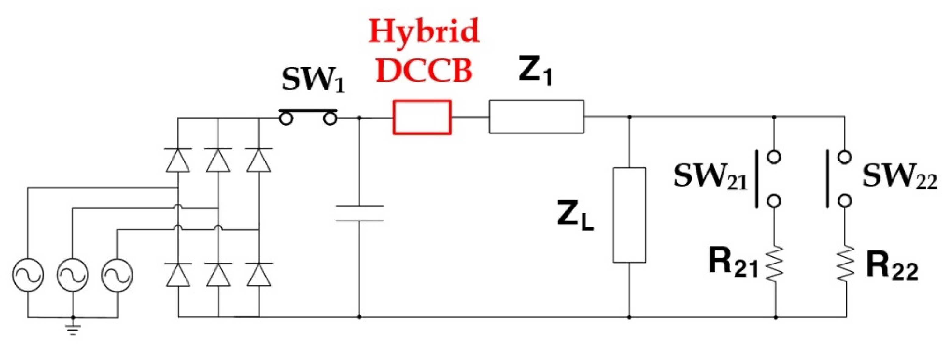
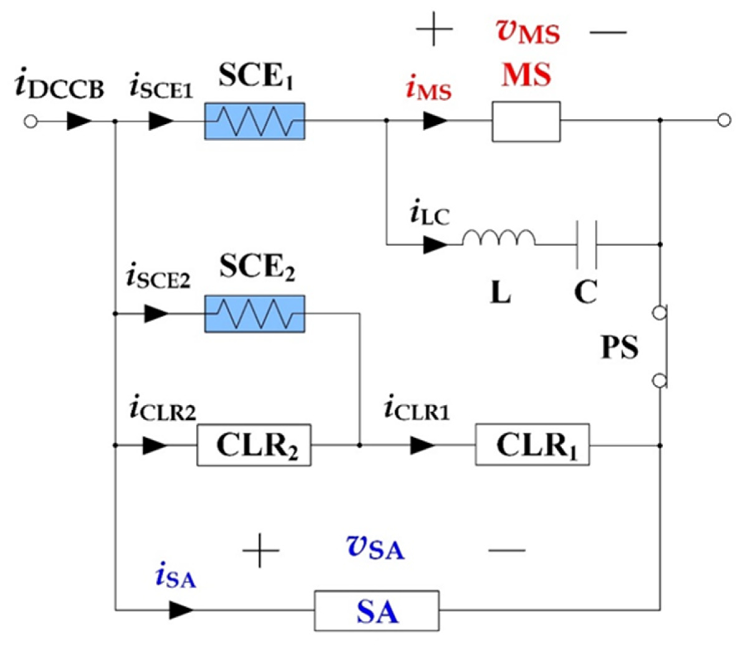
2.1. Structure of Hybrid Direct Current Circuit Breaker (DCCB) Using Double Quench

The structure of the hybrid DCCB using double quench consists of two CLRs and two SCEs as DC current limiting components, MS, LC series circuit and PS as DC current interrupting components, and surge arrestor (SA) as overvoltage prevention as shown in Figure 1. The series resonance circuit has a parallel connection with MS to induce zero current crossings in MS in case of the DC fault current occurrence. PS, connected in series the controller. The SCE1 acts as both the fault detector and the initial DC fault current limiter. The quench occurrence in SCE1 directly after the fault happens makes the CLR1 act as the first fault current limiter through SCE2. In case that the larger DC fault current flows into SCE2 despite the quench occurrence of the SCE1, the quench in SCE2 occurs sequentially and the second DC fault current limiting operation of the hybrid DCCB can be achieved. After the DC fault current limiting operation through single quench in SCE1 or double quench in both SCE1 and SCE2 comprising the hybrid DCCB according to the amplitude of the DC fault current, the DC fault current interrupting operation through the MS is achieved by its opening operation and then, finally separated from the DC fault current path by the opening of PS. The SA pre-vents the over-voltage across the DCCB during the DC current limiting and the interrupting operation.

2.2. Modeling of Hybrid Direct Current Circuit Breaker (DCCB) Using Double Quench

To analyze the current limiting and the interrupting characteristics, the PSCAD/EMTDC modeling for the suggested hybrid DCCB using a double quench of two SCEs was carried out. MS, SCE, and SA were considered as the main modeling components.
For the MS’s dynamic arc behavior, the arc conductance (GMS) was reflected into the PSCAD/EMTDC modeling from Mayr’s arc model as expressed in Equation (1) and modeled to generate directly after the MS current (iMS) exceeded 8 kA. In Equation (1), G0, Q0, and τa represent the conductance of insulation material between two conducting plates, the heat energy, and the time constant of arc, respectively [11,12]. The resistance of each SCE, which generates in case that the current in SCM (iSCM1, iSCM2) exceeds the critical current (IC1, IC2), was reflected into its PSCAD/EMTDC modeling with the resistance equation, represented in Equation (2). RN and τb in Equation (2) express the normal resistance and time constant of SCE, respectively [13,14].
In addition, the PSCAD/EMTDC modeling for the SA was considered with the resistance of Equation (3) derived from its voltage and current relation with the breakdown voltage (VB) and the nonlinear index (γ) [15]. The current in the MS (iMS) directly after the DC fault occurrence can be obtained as Equation (5) from the second differential equation for the current of the MS (iMS) as shown in Equation (4). In Equations (5) and (6), n and k represent the cycle number of the zero current point in the current of MS and the ratio of the voltage variation induced in the MS (ΔvMS) over the current variation of MS (ΔiMS), respectively.
G MS ( t ) = G 0 × exp ( t 1 t v MS ( λ ) i MS ( λ ) Q 0 d λ ) × exp ( t τ a )
R SCE ( t ) = R N × 1 exp ( t τ b )
R SA ( t ) = V B γ v SA ( t ) 1 γ
d 2 i MS ( t ) d t 2 + k L d i MS ( t ) d t + 1 L C i MS ( t ) = 1 L C I CB
i MS ( t ) = I CB [ 1 e α 2 n 1 2 π sin β 2 n 1 2 π e α t sin β t   ]
α = k 2 L                     β = 1 L C ( k 2 L ) 2
To verify the merits of the suggested hybrid DCCB using double quench, the simulated DC system was constructed as shown in Figure 2. The specifications for the simulated DC system were listed in Table 1. For DC short-circuit simulation with different amplitude of DC fault current, SW21 or SW22 was closed individually for 0.01 s for larger DC fault current and lower DC fault current after SW1 was closed. The values of the parameters, described in the modeling of MS, SCE1, SCE2, and SA comprising the hybrid DCCB, were listed in Table 2 together with CLR1, CLR2, and series resonance circuit.

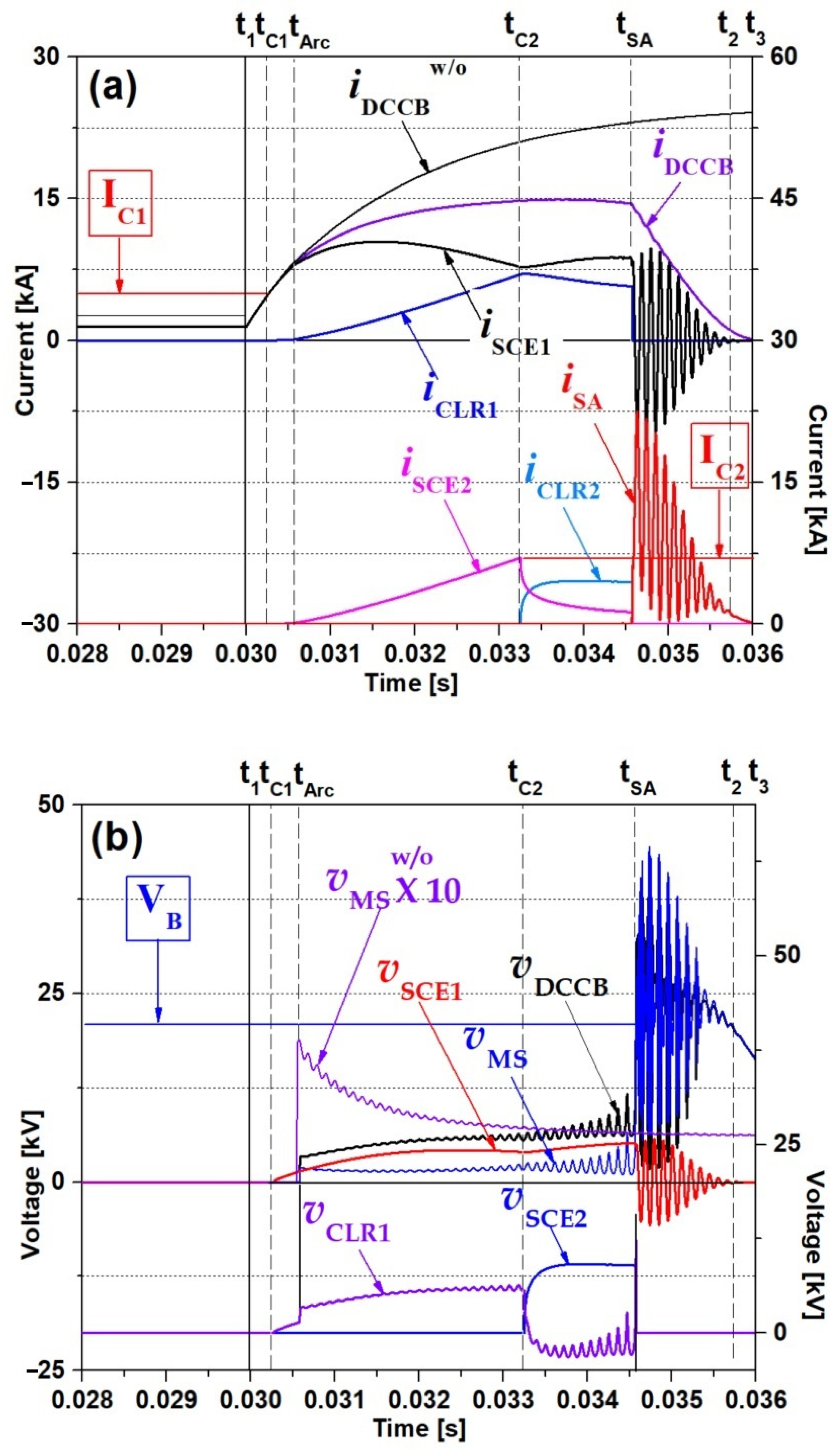
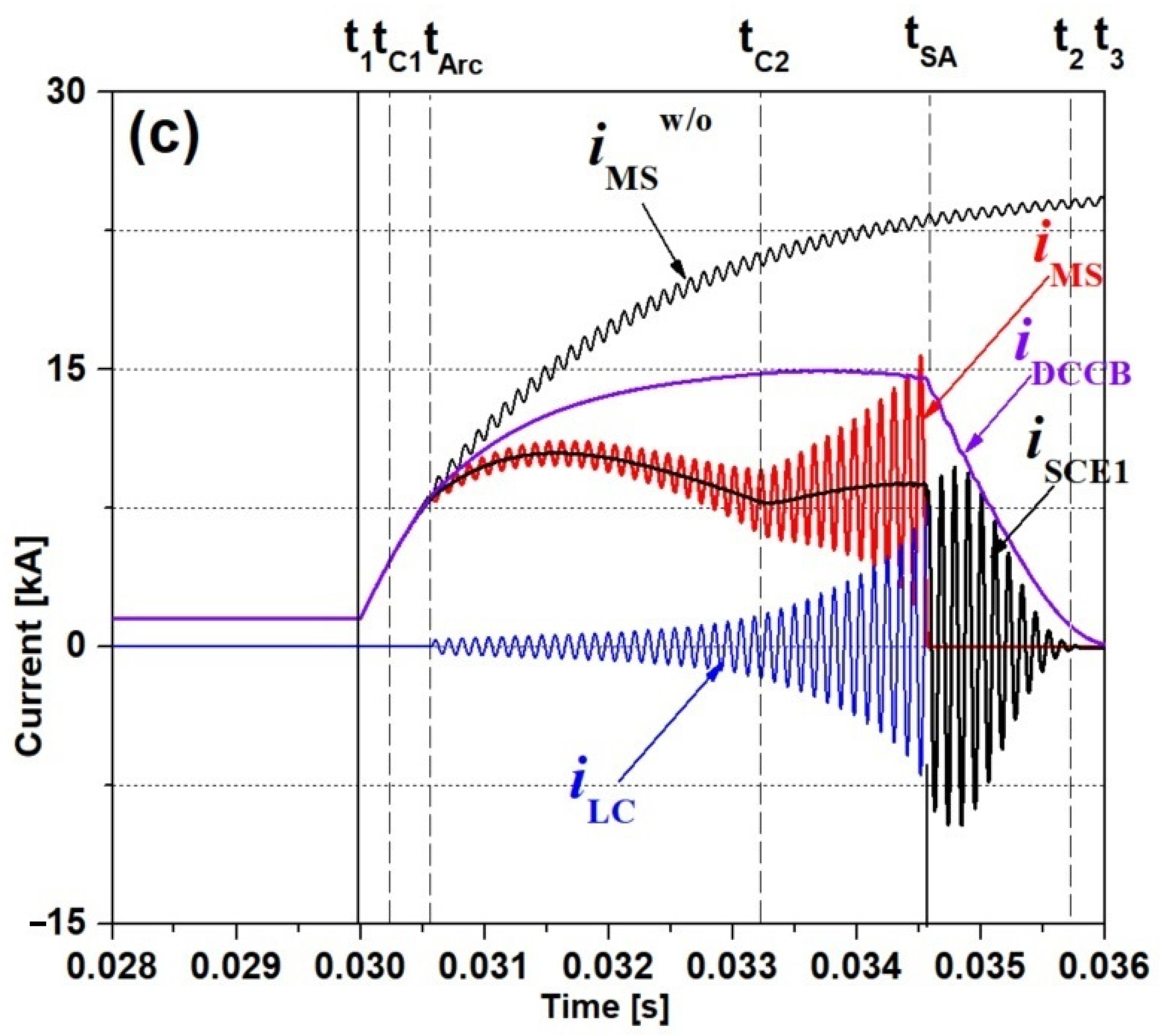
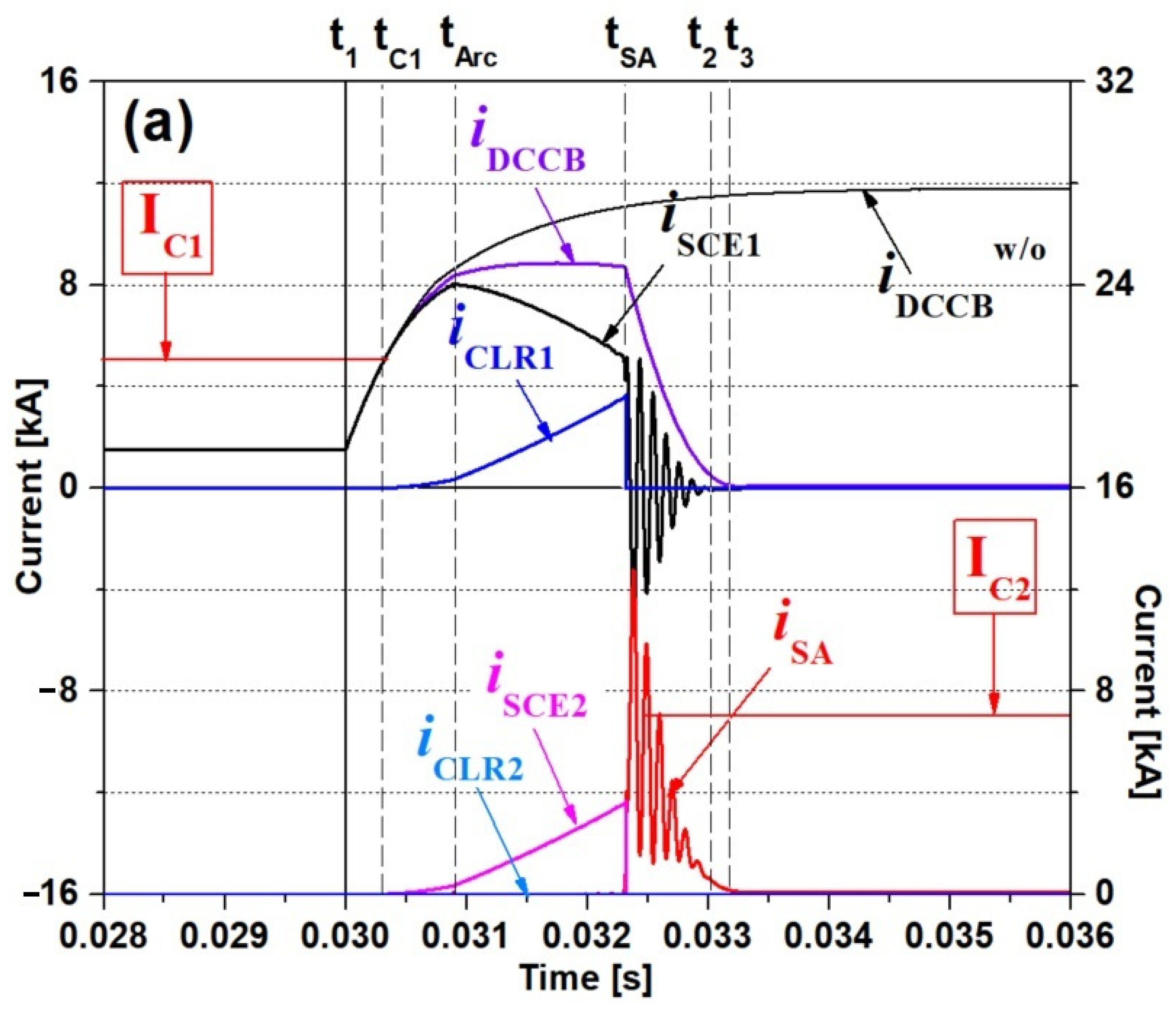
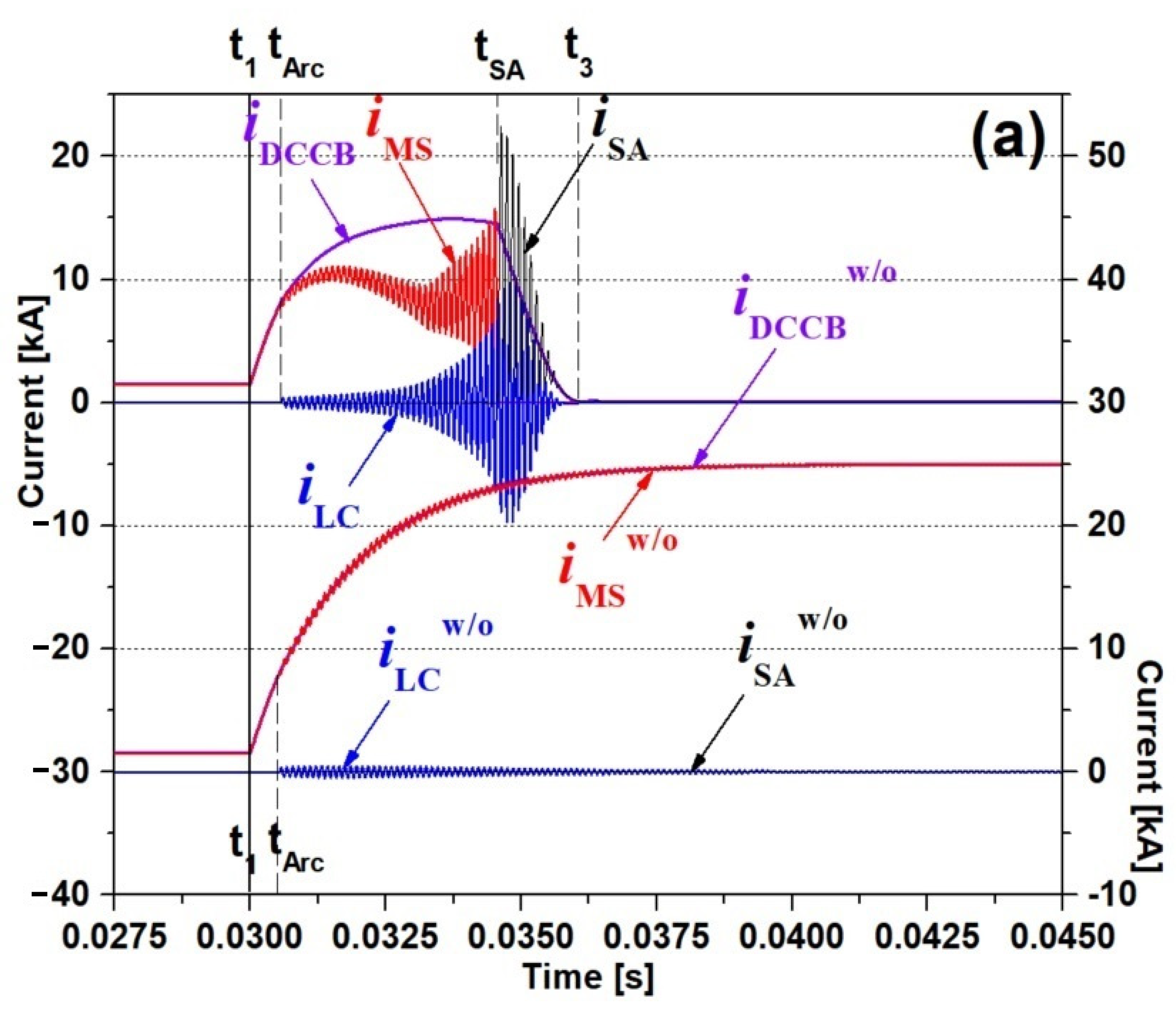
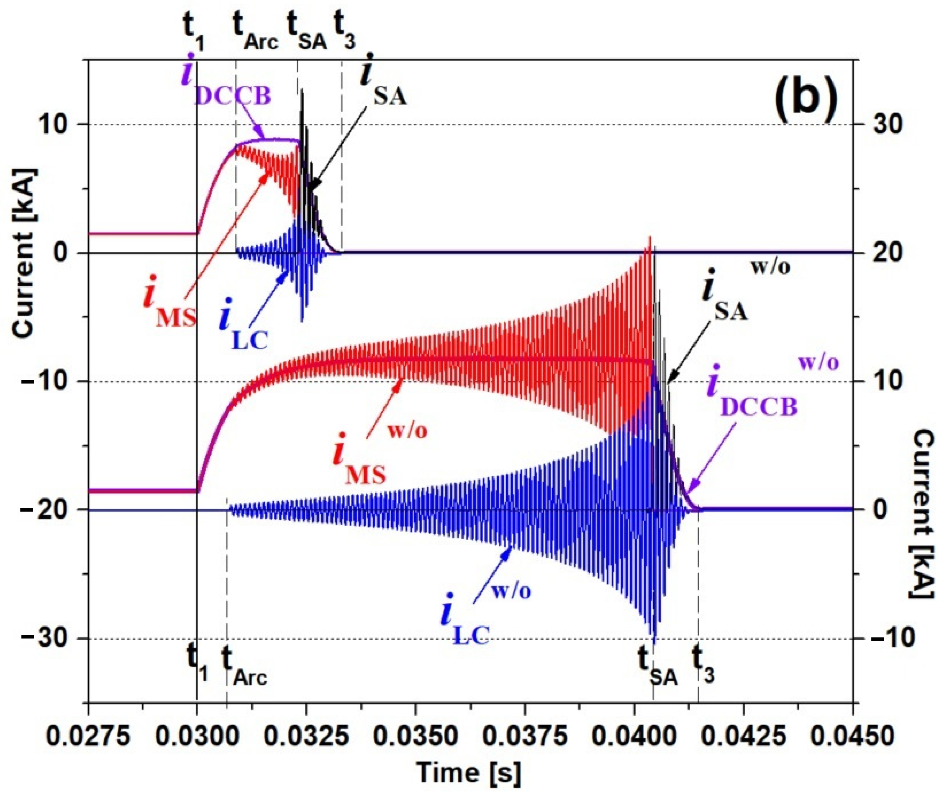
3. Results and Discussion

The improvement of the DC current limiting and interrupting operations of the suggested hybrid DCCB was analyzed from the simulation results for the larger DC fault current and the lower DC fault current situations.
Figure 3 shows the DC fault current limiting and interrupting operation of the suggested hybrid DCCB in case of the larger DC fault current occurrence. With the arc conductance in Equation (1) calculated using the voltage and the current of the MS, the voltage (vMS) and the current (iMS) of the MS were displayed in Figure 3b,c, respectively.
The fault starting time is indicated with t1 in Figure 3. After t1, the time for the current of the SCE1 (iSCE1) to arrive at the critical current (IC1) is marked with tC1. After that time, the voltage of the MS sharply increases and the arc starting time is notated with tArc as seen in Figure 3b. As tArc, the current of the MS (iMS) as seen in Figure 3c increases with the parabola form together with the resonance due to the LC series resonance circuit. Though the increase of the MS’s current, the current in the SCE1 (iSCE1) due to its quench occurrence decreases, which makes the current in the SCE2 (iSCE2) or the CLR1 (iCLR1) increase on the other way. The increased current of the SCE2 is observed to approach its critical current (IC2) at tC2. The decrease of the SCE2′s current due to its quench occurrence again causes the current of the CLR2 to be increased as seen in Figure 3a. Through twice or double quench occurrence in two SCEs and the series resonance, the current of the MS (iMS) smoothly increases with the series resonance frequency due to the series LC circuit and then, approaches the zero current point at tSA. On the other hand, the voltage of the DCCB (vDCCB) sharply starts to increase at the moment of the zero current point and exceeds the breaking voltage (VB) as seen in Figure 3b. However, the operation of the surge arrestor, as seen in the current occurrence of the surge arrestor (iSA) from Figure 3a, is confirmed to be contributed to suppressing the overvoltage of the DCCB.
After the MS opens, the current of the SCM1 (iSCE1) starts to decrease with the amplitude of the resonance frequency due to the series LC resonance circuit and then, finally approaches to zero value at t2. In the end, the current of DCCB of the hybrid DCCB reaches zero value at t3 as seen in Figure 3a.
For the comparative analysis with the hybrid DCCB without the SCMs and the CLRs, the currents of the DCCB and the MS (iDCCBw/o, iMSw/o) and the voltage of the MS (vMSw/o) were included in Figure 3. As seen in Figure 3, the MS in the case of the hybrid DCCB without the SCMs and the CLRs can be seen to be not open or fail to be open.
In the case of the lower DC fault current occurrence, which was simulated by closing SW22 after SW1 was closed as shown in Figure 2, the DC fault current limiting and interrupting operations of the suggested hybrid DCCB were displayed in Figure 4. Both the time (tC1) for the current of the SCE1 (iSCE1) to arrive at the critical current (IC1) and the time (tArc) for the voltage of the MS (vMS) rapidly to start to increase is seen to be a little longer compared to the larger DC fault current occurrence as analyzed in Figure 3. Furthermore, the second fault current limiting operation did not happen since the current of the SCE2 (iSCE2) did not exceed its critical current (IC2) as seen in Figure 4a. After tArc, the current in the MS (iMC), which kept zero value before tArc, starts to increase with the resonance frequency of series LC circuit and then, approaches zero point at tSA by the increase of the current (iLC) in series LC circuit as seen in Figure 4c.
Simultaneously, as soon as the current of the MS approaches zero point at tSA, the voltage of the MS (vMS), as shown in Figure 4b, exceeds the breaking voltage (VB), and then, the current of the surge arrestor (iSA) starts to flow as displayed in Figure 4a.
After tSA, the zero current time of the SCM1 (t2) and the zero current time of the DCCB (t3) were accompanied. This time t3 was called the complete opening time.
Due to the lower DC fault current, the voltage and current levels in components comprising the hybrid DCCB as analyzed in Figure 4 were observed to have a small scale compared to the larger DC fault current. Therefore, the complete opening time (t3) in the case of the lower DC fault current occurrence seems to be shorter than the case of the larger DC fault current. To compare the hybrid DCCB without two SCMs and two separated CLRs, the DC fault current limiting and interrupting waveforms of the suggested hybrid DCCB were displayed in Figure 5 together. In the case of the larger DC fault current occurrence, as shown in Figure 5a, the complete opening operation at t3 after the zero current in the MS through the series resonance of LC together with the twice DC fault current limiting operations of two SCMs was achieved. On the other hand, the DC fault current interrupting operation (iMSw/o, iDCCBw/o) in the case of the hybrid DCCB without two SCMs and two CLRs was not achieved.
To compare the hybrid DCCB without two SCMs and two separated CLRs, the DC fault current limiting and interrupting waveforms of the suggested hybrid DCCB were displayed in Figure 5 together. In the case of the larger DC fault current occurrence, as shown in Figure 5a, the complete opening operation at t3 after the zero current in the MS through the series resonance of LC together with the twice DC fault current limiting operations of two SCMs was achieved. On the other hand, the DC fault current interrupting operation (iMSw/o, iDCCBw/o) in case the hybrid DCCB without two SCMs and two CLRs was not achieved.
Unlike the case of the larger DC fault current occurrence, the DC fault current interrupting operation (iMSw/o, iDCCBw/o) without two SCMs and two CLRs in case of the lower DC fault current occurrence was observed to succeed as shown in Figure 5b, which was made to zero current by the series LC resonance. However, it is compared to take a longer time compared to the case of the hybrid DCCB using the double quench although the quench in only SCE1 comprising the hybrid DCCB using the double quench due to the lower DC fault current occurred.

4. Conclusions

In this paper, the hybrid DC circuit breaker using double quench was suggested and its DC fault current limiting and interrupting operation according to DC fault current amplitude was analyzed through the PSCAD/EMTDC modeling for its components. In the case of the larger DC fault current occurrence, the DC fault current interrupting operation through zero current generation in the MS using the series resonance together with the twice DC fault current limiting operations of two SCMs was successively achieved. On the other hand, the DC fault current interrupting operation in case with the hybrid DCCB without two SCMs and two CLRs was not achieved. In case of lower DC fault current occurrence, the DC fault current interrupting operation of the suggested hybrid DCCB was also made through once DC fault current limiting operation. However, the opening time was shorter than the case of the larger DC fault current.
In the future, the studies considering the application of the suggested hybrid DCCB into the multi-terminal MVDC system, which requires several DCCBs with different capacities, will be in progress.

Author Contributions

Writing—original draft, S.-H.L.; Writing—review and editing, S.-J.C.; Formal analysis, J.-H.L.; Investigation, J.-W.L. All authors have read and agreed to the published version of the manuscript.

Funding

This work was supported by the Soongsil University Research Fund (Convergence Research) of 2020 and was also supported by the National Research Foundation of Korea (NRF) grant funded by the Korean government (MOE) (No. 2020R1F1A1077206).

Institutional Review Board Statement

Not applicable.

Informed Consent Statement

Not applicable.

Data Availability Statement

Data is contained within the article.

Conflicts of Interest

The authors declare no conflict of interest.

References

  1. Nakao, H.; Nakagoshi, Y.; Hatano, M.; Koshizuka, T.; Nishiwaki, S.; Kobayashi, A.; Murao, T.; Yanabu, S. DC Current Interruption in HVDC SF6 Gas MRTB by Means of Self-Excitation. IEEE Power Eng. Rev. 2001, 21, 62. [Google Scholar] [CrossRef]
  2. Callavik, M.; Blomberg, A.; Häfner, J.; Jacobson, B. Hybrid HVDC Breaker. ABB Grid Syst. Tech. Pap. 2012, 361, 143–152. [Google Scholar]
  3. Sneath, J.; Rajapakse, A.D. Fault Detection and Interruption in an Earthed HVDC Grid Using ROCOV and Hybrid DC Breakers. IEEE Trans. Power Deliv. 2016, 31, 973–981. [Google Scholar] [CrossRef]
  4. Meyer, C.; Kowal, M.; de Doncker, R.W. Circuit breaker concepts for future high-power DC-applications. In Conference Record of the 2005 Industry Applications Conference, Proceedings of the Fourtieth IAS Annual Meeting, Kowloon, Hong Kong, 2–6 October 2005; Institute of Electrical and Electronics Engineers: Piscataway, NJ, USA, 2005. [Google Scholar] [CrossRef]
  5. Thomas, D.W.P.; Pereira, E.T.; Christopoulos, C.; Howe, A.F. The simulation of circuit breaker switching using a composite Cassie-modified Mayr model. IEEE Trans. Power Deliv. 1955, 10, 1829–1835. [Google Scholar] [CrossRef]
  6. Lee, J.; Khan, U.A.; Lee, H.; Lee, B. Impact of SFCL on the Four Types of HVDC Circuit Breakers by Simulation. IEEE Trans. Appl. Supercond. 2016, 26, 1–6. [Google Scholar]
  7. Xiang, B.; Tan, Y.; Yang, K.; Liu, Z.; Geng, Y.; Wang, J.; Yanabu, S. Quenched Resistance Effects on a Superconducting Current-Limiting-Type DC Breaker. IEEE Trans. Appl. Supercond. 2016, 26, 1–5. [Google Scholar] [CrossRef]
  8. Zhoua, G.; Hana, M.; Filizadehb, S.; Caoa, X.; Huang, W. Studies on the combination of RSFCLs and DCCBs in MMC-MTDC system protection. Int. J. Electr. Power Energy Syst. 2021, 125, 106532. [Google Scholar] [CrossRef]
  9. Liang, S.; Tang, Y.; Ren, L.; Xu, Y.; Shi, J.; Li, Z.; Tan, X. Parameter Matching and Optimization of a Hybrid Type DC SFCL Considering the Transient Characteristics of VSC-Based DC Systems. Energies 2019, 12, 3522. [Google Scholar] [CrossRef] [Green Version]
  10. Lee, H.; Asif, M.; Park, K.; Lee, B. Feasible protection strategy for HVDC system by means of SFCL and passive resonance DC breaker. IET J. Eng. 2019, 2019, 767–770. [Google Scholar] [CrossRef]
  11. van der Sluis, L. Transients in Power Systems; John Wiley & Sons: Hoboken, NJ, USA, 2001. [Google Scholar]
  12. Walter, M.M. Switching Arcs in Passive Resonance HVDC Circuit Breakers. Ph.D. Thesis, ETH Zürich, Zürich, Switzerland, 2013. [Google Scholar]
  13. Yamaguchi, H.; Kataoka, T. Current Limiting Characteristics of Transformer Type Superconducting Fault Current Limiter with Shunt Impedance and Inductive Load. IEEE Trans. Appl. Supercond. 2008, 18, 668–671. [Google Scholar] [CrossRef]
  14. Babaei, M.; Abdelwahed, S.; Kluss, J.V.; Jafari-Marandi, R. A novel approach for optimal design of superconducting fault current limiter. In Proceedings of the 2018 IEEE Texas Power and Energy Conference (TPEC), College Station, TX, USA, 12 March 2018. [Google Scholar]
  15. Žitnik, B.; Babuder, M.; Muhr, M.; Žitnik, M.; Thottappillil, R. Numerical Modelling of Metal Oxide Varistors. In Proceedings of the XIVth International Symposium on High Voltage Engineering, Beijing, China, 25–29 August 2005. [Google Scholar]
Figure 1. Structure of hybrid Direct Current (DC) circuit breaker using double quench; SCE: superconducting element; MS: mechanical switch; CLR: current limiting resistor/reactor; SA: surge arrestor; PS: power switch.
Energies 14 04157 g001
Figure 2. Simulated DC system for the operation of hybrid DCCB using double quench; Z1: line impedance; ZL: load impedance; R21: small DC fault resistance; R22: large DC fault resistance.
Energies 14 04157 g002
Figure 3. DC fault current limiting and interrupting operation waveforms of the hybrid DCCB using double quench in case of the larger DC fault current occurrence. (a) Current waveforms of DCCB, SCE1, SCE2, CLR1, CLR2 and SA (iDCCB, iSCE1, iSCE2, iCLR1, iCLR2, iSA). (b) Voltage waveforms of DCCB, MS, SCE1, SCE2, CLR1 (vDCCB, vMS, vSCE1, vSCE2, vCLR1). (c) DC current limiting and interrupting waveforms of DCCB, MS, LC, SCE1 (iDCCB, iMS, iLC, iSCE1).
Energies 14 04157 g003aEnergies 14 04157 g003b
Figure 4. DC fault current limiting and interrupting operation waveforms of the hybrid DCCB using double quench in case of the lower DC fault current occurrence. (a) Current waveforms of DCCB, SCE1 SCE2, CLR1, CLR2 and SA (iDCCB, iSCE1, iSCE2, iCLR1, iCLR2, iSA). (b) Voltage waveforms of DCCB, MS, SCE1, SCE2, CLR1 (vDCCB, vMS, vSCE1, vSCE2, vCLR1). (c) DC current limiting and interrupting waveforms of DCCB, MS, LC, SCE1 (iDCCB, iMS, iLC, iSCE1).
Energies 14 04157 g004aEnergies 14 04157 g004b
Figure 5. Comparative waveforms of DC fault current limiting and interrupting operation of the hybrid DCCB using double quench for the case without the hybrid DCCB. (a) In case of the larger DC fault current occurrence, (b) In case of the lower DC fault current occurrence.
Energies 14 04157 g005aEnergies 14 04157 g005b
Table 1. Specification of DC System for DC Short-Circuit Tests.
DC System CircuitParametersValueUnit
DC source voltageVDC15kV
Line impedance (Z1)R10.01Ω
X10.377Ω
Load impedance (ZL)RL0.6Ω
Small DC Fault ResistanceR210.6Ω
Large DC Fault ResistanceR221.2Ω
Table 2. Design Parameters of Components Comprising Hybrid DCCB using Double Quench.
ComponentsDescriptionParametersValueUnit
MSConductance of insulation materialG05.5 × 1015-
Heat energyQ015-
Time constant of arcτa1-
Series Resonance CircuitSeries inductanceL87μH
Series capacitanceC3.33μF
SCE1Normal resistance of SCE1RN11Ω
Normal resistance of SCE2RN220Ω
SCE2Time constant of SCE1 & SCE2τb0.1-
Critical current of SCE1IC15kA
Critical current of SCE2IC27kA
CLR1Current limiting reactanceLCLR2mH
CLR2Current limiting resistanceRCLR2Ω
SAbreakdown voltageVB20kV
nonlinear indexγ8
Publisher’s Note: MDPI stays neutral with regard to jurisdictional claims in published maps and institutional affiliations.

