1. Introduction
The need for reliable renewable energy sources has prompted vast research in vibration energy harvesting [
1,
2]. Coupled with health monitoring systems of big structures, (bridges, buildings, and aircraft) numerous harvesters have been designed and deployed to replace depletable batteries in low-power wireless sensors and remote controllers. This is a breakthrough in the autonomous world and prognostics. The essence of energy harvesting is to complement replaceable batteries because the location of such devices (sensors and controllers), may limit their accessibility, and chemical batteries when over-relied upon, may be hazardous to the environment at the end of their useful life. The harvesters use different configurations and transduction mechanisms like electrostatics, electromagnetism, and now predominantly piezoelectric materials, whose primary advantage is high power density and elevated voltage output [
3,
4]. Consequently, vibrations, which are an unwanted occurrence, can be put into beneficial use and they are readily available in form of human motion, machine vibration, wind, etc.
The idea of vibration energy harvesting, initially presented by Williams and Yates (1996) [
5], has significantly evolved. The architecture of a traditional piezoelectric energy harvester (PEH) comprises a rectangular cantilever beam with piezoelectric elements on its surface. The beam provides the necessary elasticity, whereas the piezoelectric member performs mechanical-to-electrical conversion of the strain induced by vibration. The arrangement is either unimorph or bimorph, and the output from the piezoelectric patch is dependent on its shape; for instance, Elahi [
6] inferred that a rectangular path was more efficient than a circular one. Moreover, the length of the patch relative to the length of the driving beam influences the harvester’s performance, as [
7] reported that induced voltage per tip deflection is maximum for equal lengths of the PZT-5A and Al combination. A mass may be attached to the unconstrained end to tailor the resonance frequency [
8,
9]. Cantilever harvesters’ operation is best at their resonances, and so therefore the excitation source frequency needs to match their natural frequencies. Conventional linear piezoelectric harvesters (CPEH) perform on a single resonant frequency (i.e., the fundamental frequency), and higher modes are not used in energy generation because they are far from the fundamental frequency. These harvesters are thus called narrow bandwidth harvesters. Several attempts have been made to broaden the operation bandwidth range by incorporating non-linearities [
10,
11,
12], use of magnets [
13,
14], parallel arrangement of elements, and even adding attachments to the main beam [
10,
15,
16,
17].
Integration of magnetic interactions in the harvesters induces the hardening effect to widen the bandwidth, and also transform the harvesters into hybrid harvesters. For example, Tadesse et al. [
18] designed a cantilevered harvester with a magnet at the unrestrained end to serve as a mass and a transducer. As the beam vibrates, the magnet oscillates inside a static coil. Power was generated by electromagnetic induction at low frequency and piezoelectric transduction at high frequency. Such a harvester is termed a hybrid harvester. Wang et al. [
19], presented a two DOF magnetic coupled PEH to increase energy density through enhancing the bandwidth. Permanent magnets attached on the unrestrained end serve as the tuning masses, and at the same time, their magnetic forces provide nonlinearities to enhance the broadband. The device was effective over wider broadband. Wang and Tang [
20] investigated a bistable two DOF PEH having a parasitic oscillator. The device is magnetically coupled, and proper adjustment of the oscillator provides desirable nonlinear dynamics over two peaks which outperforms traditional PEH. On the other hand, Bouhedma et al. [
21] magnetically tuned a multimodal PEH. The first two frequencies of the proposed design are in the range of 50–100 Hz. Fixed magnets and permanent magnets incorporated on the structure provide for frequency up or down tuning. A quads Table 2-DOF PEH was later presented by Zayed et al. [
22], which comprises an inner beam and outer beams to form a cut-out structure. Proper selection of gaps and placement of magnets ensures the achievement of two resonant peaks.
A parallel array of elements also plays a part in bandwidth broadening. Wu et al. [
23] investigated an M-shaped PEH with one main beam and two secondary beams. Natural frequencies are tuned close enough, 14.3 Hz to 23.4 Hz, to achieve broadband harvesting. Meruane and Pichara [
15] constructed an arrangement of piezoelectric cantilever beams linked by springs. An increase in power output and the maximum frequency band were achieved. However, the variation of spring stiffness was not fully investigated. Later, Li et al. [
24] presented a multimode PEH with the main beam and an arrangement of affiliated beams with end masses. Variation of the number of branches, tip masses, and dimensions of the branches can effectively tune the number and magnitude of resonant peaks. Higher normalized power and power density were achieved.
Through rearrangement of masses and changing the harvester’s orientation, many researchers have attempted to achieve multiple resonances. A cutout structure trident beam is presented in [
25] similar to that in [
22] but without magnets. To enhance the amplitude of the second mode, a second trident beam is connected to the first, and a large second peak is obtained. Ertuk et al. [
26] reported voltages of 14.8 V/g and 11.3 V/g from an L-shaped piezoelectric assembly with masses for frequency tuning at resonance frequencies of 17.0 Hz and 49.7 Hz, respectively. The structure was intended for use in the landing gear of unmanned air vehicles. In 2010, Qi et al. [
27] proposed a multimodal harvester made of a fixed-fixed beam. Side beams are mounted to the main beam. The frequency is tuned by varying the tip masses of the side beams and multiple peaks were realized. A 2DOF system made up of two cantilever beams and a proof mass was presented by Kim et al. [
28]. It exploits both rotational and translational motion and achieved better efficiency than conventional PEH by realizing two resonant peaks. Further, Tang and Yang [
29] theoretically presented a multi-DOF design featuring a base, mass, and piezoelectric element resulting in a wider bandwidth. This provided a tool for the parametric study of an n-DOF PEH. A branched beam-based harvester was proposed by Zhang and Hu [
30]. The structure has a main beam bonded with the piezoelectric element. Several branches are attached to the beam to provide different resonant frequencies. This work was followed by Upadrashta et al. [
31] who proposed a trident harvester, with three secondary beams bolted to the main beam. Tip masses on the secondary beams are used in tuning the resonant frequencies, similarly, Izadgoshasb et al. [
32] upgraded the performance of a multi-resonant harvester by the use of a rectangular beam with two triangular branches. Through optimization of the harvester parameters like geometric dimensions, a better broadband performance was achieved. It was recommended for further investigation in configurations with more than two attached branches, and a configuration with a circular base. Li et al. [
33] used multiple attached masses to tune the resonant frequencies of a harvester. Different movable masses are placed along the span of the beam and as well as discretely. It was inferred that the sensitivity and bandwidth of the cantilever beam can be enhanced by changing the magnitude, position, and sum of masses. Sun et al. [
34] presented a revolutionary structure that transforms planar harvesters to 3D harvesters, by mechanically coupling four beams to a central bridging beam. It is highly tunable by enhancing the strain through the incorporation of buckling and the optional inclusion of Kirigami cut patterns. Broadband and multidirectional harvested energy was obtained in the x, y, and z directions, with superior capability in the z-direction.
While many techniques have been developed, they employ the addition of extra attachments to the main beam, the use of magnets, or an array of parallel beams. These require a reasonable amount of space, which inhibits their versatility. Arrayed harvesters reduce power density and also require a quite large excitation force that cannot be readily obtained from the ambient environment. Therefore, this paper proposes a split cantilever multi-resonant energy harvester (SCMEH) featuring a compact and homogenous structure free of linkages and hence effective with low base acceleration. It is versatile since it can effortlessly be modified to suit target vibration sources, and thus it can be used in a wide range of applications. Also, it requires low excitation forces as it doesn’t have links which makes it suitable for the ambient environment. The design minimizes phase differences and thereby achieves higher peak energy when compared to other designs explored in the literature. The main cantilever beam is split by parallel grooves to form parallel branches. Each branch has a tip mass to tune the resonant frequency. A parametric study is carried out in COMSOL finite element method (FEM) to obtain a satisfactory design. The design intends to generate power, at multiple resonant peaks and at low-frequency vibration excitation such as ambient wind vibrations, without sacrificing the capacity to generate sufficiently high voltage.
2. Design and Modeling of the Split Cantilever Multi-Resonant Energy Harvester
The SCMEH which is shown in
Figure 1a comprises a brass split cantilever beam bonded by PZT-5H piezoelectric material on its upper and lower surfaces to form a bimorph. The active layers cover the entire beam length. Masses
m1,
m2, and
m3 are placed on the tips of branches 1, 2, and 3, respectively, as illustrated in
Figure 1b. The width
w1,
w2, and
w3 of the branches are 2 mm, 3 mm, and 5 mm, respectively. The variation of the widths has no significant effect on the magnitude of resonance [
35]. The basic reason for the variation is to reduce out-of-phase vibration, which in turn reduces the strain induced on the piezoelectric element [
31]. The size of the groove is 1 mm and is constant for both grooves. Increasing the number of grooves increases the number of DOF, and in turn, the number of resonant peaks attained. The masses in
Figure 1a are configured according to the available space, and their orientation does not affect the performance of the harvester.
When subjected to base excitation, the base energy will be transferred to the beam, and the individual branches will vibrate, each at its fundamental frequency. This effect will influence the frequency of the whole structure by reducing the separation between the first three vibration modes. The fourth and subsequent modes are too high to be considered. The tip masses are effectively adjusted to tune the resonant frequencies. This work seeks to find an adequate design to achieve the targeted natural frequency to be less or equal 15 Hz. The individual parameters considered in the intuitive selection process are the tip masses, the length of the branches, and the root length.
Electromechanical Model
On the application of mechanical stress on the SCMEH, the substrate material elastically deforms. The deformation induces strain on the piezoelectric element, and a direct piezoelectric effect is experienced. The electromechanical coupling governing equations are stated in a strain-charge matrix as follows:
where
and
are the mechanical strain, mechanical stress, electrical displacement, and electric field tensor, respectively, while
is the permittivity matrix and
is the elastic compliance matrix of the piezoelectric material.
and
are direct and inverse piezoelectric effect matrices, respectively. The superscript
denotes zero or constant electric field, Superscript
t denotes the transpose of a matrix, and superscript
denotes zero or constant stress field. The inverse and direct piezoelectric effects are expressed by Equations (1) and (2), respectively.
Since the SCMEH is under direct effect, the poling Equation (2) is written as:
where
,
and
are piezoelectric constants,
,
and
are normal stresses along the x, y, and z axes, respectively.
,
and
are the shear stresses. The SCMEH harvester beam dominantly vibrates in the z-axis direction; hence the piezoelectric material undergoes a stress state along the x-axis. Under this configuration, Equation (3) becomes:
The above equations are coupled with the mechanical response of the harvester and solved by FEM simulation in COMSOL Multiphysics.
3. FEM Analysis
In this study, FEM analysis is carried out in COMSOL Multiphysics. Two FEM studies are conducted: modal analysis to determine the eigenfrequencies for designing the harvester, and harmonic analysis to determine the response of the harvester. A fixed constraint is applied at the root to imply the fixed side of the cantilever. Respective materials are chosen from the material library, and respective boundary conditions are applied. The boundary conditions include acceleration, initial displacement, resistance, damping, and terminals. Acceleration is set to be 0.2 g and the initial displacement is set to be zero. A loss factor of 0.001 is selected to represent the damping. Ground and terminals are set such that the configuration assumes a parallel connection. Load resistance of 10 kΩ is adopted to depict an open circuit condition. Although it is common to use very large resistances in FEM to emulate infinite resistance [
31], an adequate resistance will be determined later in this study. Material properties used in the simulation are presented in
Table 1.
The FEM mesh size is carefully selected, such that the solution dependency on the number of elements is small as possible while maintaining a reasonable computational time. Two FEM analyses are conducted in this study: first is the modal analysis to determine the mode shapes and resonant frequencies that will aid in designing the SCMEH and second is the harmonic analysis to determine the harvester’s performance and validate the modal analysis result. On the other hand, PZT-5H is selected because of its higher piezoelectric constant and produces high power values [
36]. Brass is the preferred substrate material because its higher modulus withstands a substantial amount of tip mass before initial curvature occurs, allowing for use in a variety of vibration sources.
3.1. Modal Analysis
Modal analysis using the above-stated boundary conditions is conducted to determine the first three eigenfrequencies. The analysis is first carried out without any tip mass, with a 60 mm length L, 50 mm branch length for all branches, and a 10 mm root length Lr. The system is solved as a continuous system and the first three fundamental frequencies are chosen since the fourth and other subsequent frequencies are very high and separated from the third fundamental frequency. The first, second, and third natural frequencies are found to be 113.68 Hz, 132.74 Hz, and 140.48 Hz, respectively. The values of the obtained eigenfrequencies are too high compared to the targeted frequency range. Therefore, attempts are made to tune the frequencies to the desired range as discussed in the following sections.
3.2. Parameter Selection Study
3.2.1. Effect of Mass on the Natural Frequency
The weight of tip mass is known to decrease the natural frequency [
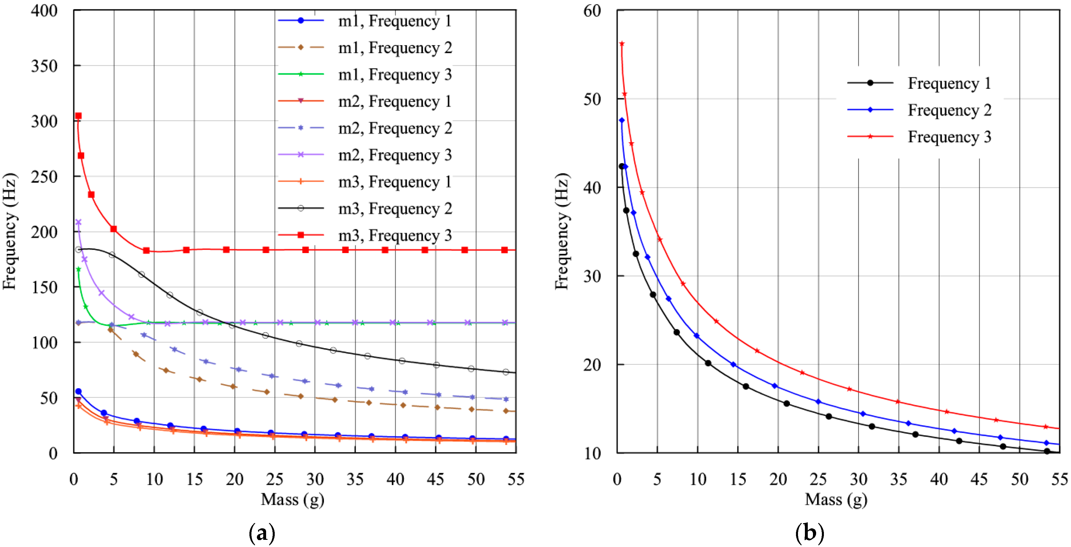
37]. To determine its effect on the SCMEH, the tip mass was varied from 1 g to 55 g, and modal analysis was repeatedly conducted to determine the first three fundamental frequencies.
The addition of tip mass to the branches independently has a significant effect on the fundamental frequencies compared to those of the system without tip masses as shown in
Figure 2.
Figure 2a depicts the result of independently applying masses on the branches. When one branch is loaded while leaving the other two branches without any mass, the first fundamental frequency drops greatly, the second natural frequency drops moderately while the third natural frequency drops slightly, compared to a system without tip masses. The magnitude of the frequencies decreases with increasing mass, to a point where it remains constant even though the mass is increased. In addition, the separation between the frequencies is very large, and any attempt to achieve broadband power by the addition of tip mass to a single branch seems futile. In
Figure 2b, tip masses are collectively increased gradually on all the branches. It is noted that the separation between the fundamental frequencies declines rapidly. The magnitude of the fundamental frequencies also decreases as the mass increases. It is noted that at a specific point, the effect of increasing mass on the frequency is small, where further addition does not have a great effect on the magnitude of the frequencies. Consequently, moderate mass magnitudes should be selected to avoid inducing excessive strain, which would result in fast degradation. The masses for
m1,
m2, and
m3 have been chosen to be 49 g, 41 g, and 51 g, respectively, under which the desired frequencies are attained without an initial curvature of the beam before excitation.
3.2.2. Effect of Root Length (Lr) and Branch Length (L) on the Natural Frequencies
Figure 3 illustrates the effect of both root length (
Lr) and branch length
L on the magnitude of the natural frequencies. As seen in
Figure 3a, the magnitude of natural frequencies increases as the root length increases. Furthermore, at higher values of
Lr, the separation between the frequencies is large. The simulation results showed that at short distances, below 6 mm, an initial deflection would occur without excitation under the chosen mass. On the other hand, at long lengths of 18 mm or more, more strain would be induced at the root of individual branches rather than at the root of the structure as intended. Based on the data, a root length of 8 mm is appropriate for the SCMEH to attain the desired natural frequency.
Figure 3b shows that increasing branch length results in a decrease in natural frequency.
When the length exceeds 60 mm for all branches, initial curvature is expected to occur without application of external excitation, and extreme deflection may occur during operation, leading to premature yielding. To achieve a reasonable separation of the resonant frequencies, the length of individual branches should be slightly varied. With equal length, the natural frequencies tend to coincide, an occurrence that will give low second and third peaks since the piezoelectric element will not have fully recovered from the strain induced by the preceding resonant vibration. The proper separation between the frequencies is desirable to distribute the frequencies desirably. The length selected for branches 1, 2, and 3 is 32 mm, 42 mm, and 52 mm, respectively. The proposed design, whose parameters are shown in
Table 2 is further analyzed and deployed to maximize the harvested energy.
3.3. Modal Analysis of SCMEH
The sufficient geometry of the SCMEH obtained from the parameter selection study in the previous section is further subjected to modal analysis to determine its mode shapes that will be used to study its response. The first three resonant frequencies obtained are 10.702 Hz, 12.724 Hz, and 14.007 Hz, respectively.
Figure 4a shows the 1st mode shape with branch 3 having the maximum deflection while branches 2 and 1 have a very minute deflection in the opposite direction. Maximum strain is induced due to insignificant phase differences. This indicates that the first resonant frequency is only dominated by the effect of branch 1.
Figure 4b shows the 2nd mode shape, with a maximum deflection in branch 2, and a slight deflection in branch 1, in a similar direction, and branch 3 towards the contrary direction. The significant phase difference experienced slightly lowers the strain induced on the harvester materials. On the other hand,
Figure 4c shows the 3rd mode shape, with maximum displacement in branch 1 and a notable displacement of branch 2 in the opposite direction. There is a large phase difference in the 3rd mode and hence it’s the mode with the lowest strain. Induced strain is proportional to harvested energy.
3.4. Harmonic Analysis
Harmonic analysis is carried out to verify the eigenfrequencies obtained by modal analysis, and to determine the frequency response of the system. A base excitation of 0.2 g is applied at the fixed end of the harvester, and a 10 kΩ load resistance is connected across the terminal. Frequency response in terms of voltage and power is determined.
3.4.1. Frequency Response: Voltage and Power
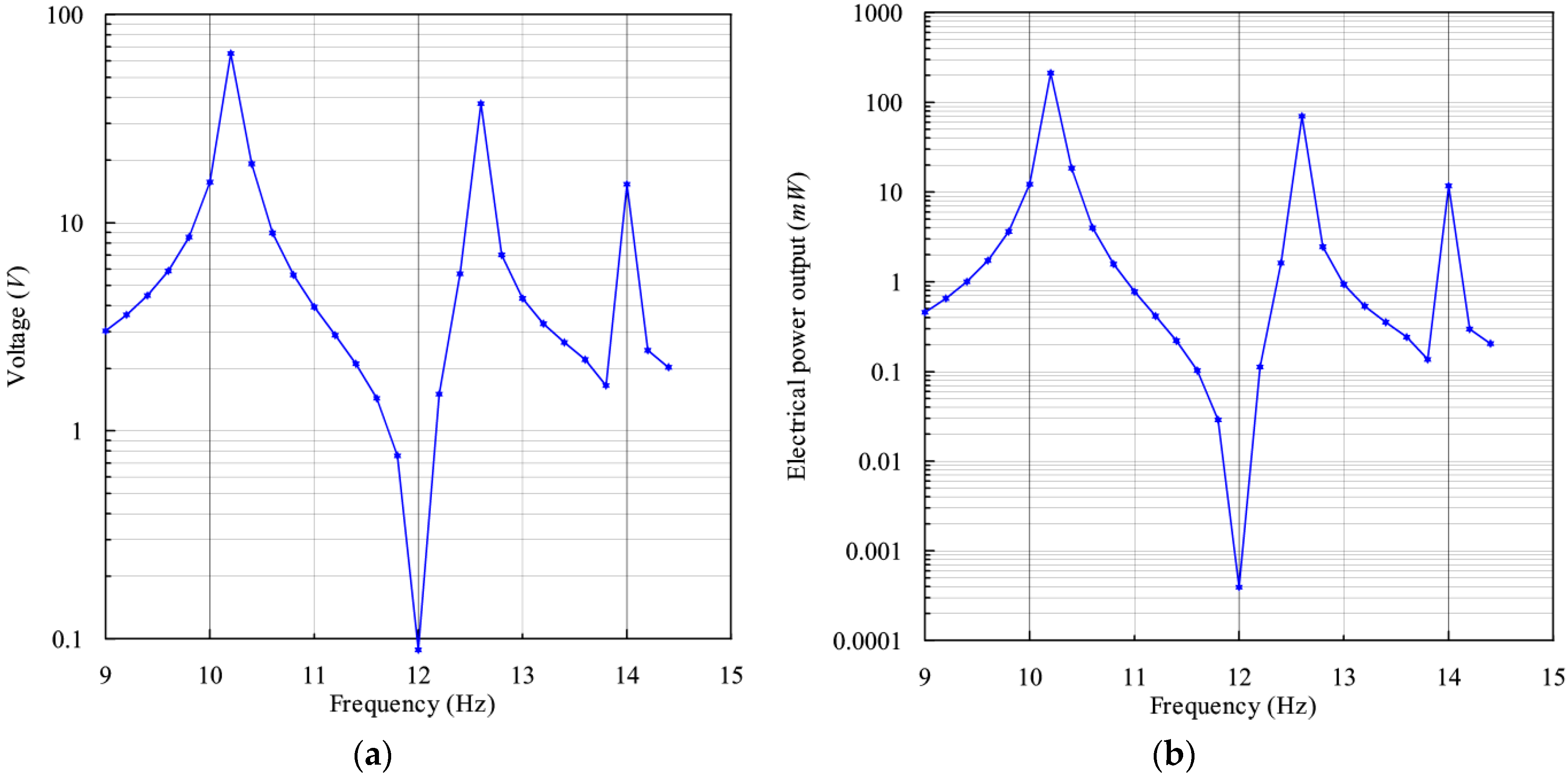
The resonant frequencies obtained are 10.25 Hz, 12.6 Hz, and 14.0 Hz, respectively. A slight variation in the frequencies is noted compared to the ones calculated in modal analysis. This is because of electrical loading, which increases the damping effect, and in return, alters the stiffness of the structure [
38]. The frequency behavior in relation to voltage and power is calculated at frequencies ranging between 9 Hz and 14.5 Hz and presented in log scale in
Figure 5.
Figure 5a shows the voltage obtained. The voltage increases as the frequency tends to resonance and drops as the frequency tends away from resonance. A peak voltage of 65.11 V is experienced at the first resonant frequency, where the beam vibrates with a minimal phase difference. At the second resonant frequency, an intermediate voltage of 37.41 V is generated, while at the third resonant frequency, the lowest voltage of 15.32 V is experienced because the phase difference is quite larger than in the first two cases. Conspicuously, there is a large dip between peaks one and two, at a frequency of 12 Hz. This frequency is the anti-resonant frequency whereby the vibration amplitude drops to almost zero due to destructive interference in the coupled harvester components. The antiresonance phenomenon commonly occurs in multi-DOF systems [
39,
40]. On the other hand, the power generated has similar characteristics with the voltage as seen in
Figure 5b. The peak values are 212.8 mW, 69.95 mW, and 11.73 mW, respectively, for resonant peaks one, two, and three, with the theoretical relationship between the voltage and power being
. The disparity among peak magnitudes is brought about by the phase differences highlighted in
Section 3.3. above.
3.4.2. Performance at Optimal Load Resistance
To evaluate the adequate load resistance for best performance, a parametric sweep is conducted for different resistance values ranging from 100 Ω to 10 M Ω. The effect of load resistance on the deflection of the harvester is such that the deflection will decrease with increasing load. This is because electrical damping is induced in the harvester, and it is proportional to the load resistance. Theoretically, the tip deflection is minimum at a load resistance of where ω is the oscillation frequency in rad/s. This implies the existence of a critical resistance value for maximum power since both extremely high and extremely low impedance values have adverse effects on harvesters’ performance.
The plot in
Figure 6a shows the variation of voltage with the load resistance. The figure shows that as resistance increases, the voltage increases to an asymptotic value where there is no further effect.
Figure 6b explores the effect of load on power; the power increases to a maximum value and starts to decrease again to a minimum value, with increasing load resistance because power is largely dependent on impedance. The findings indicate that the adequate load resistance is 5.62 kΩ. Therefore, proper load choice will enhance the performance of the harvester.
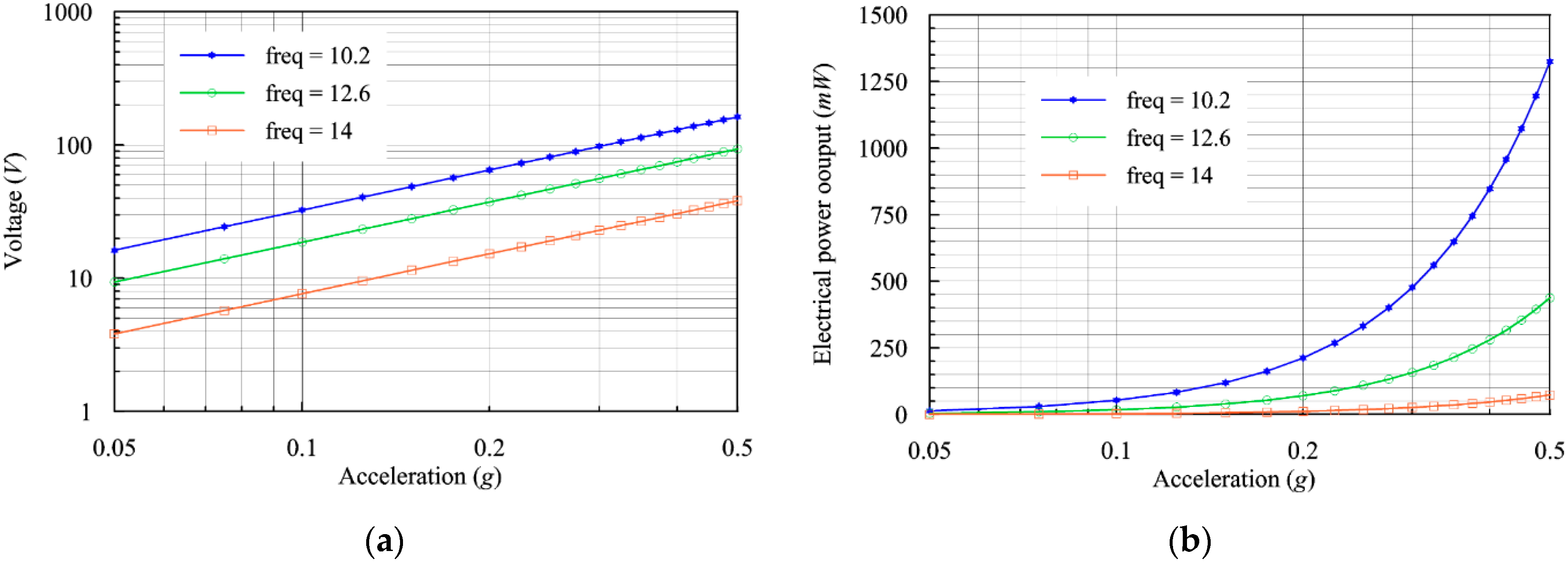
3.4.3. Performance under Varying Acceleration
The performance of the SCMEH greatly relies on the applied force, which is applied as base acceleration and is naturally expected to be proportional. The acceleration is increased from 0.05 g to 0.5 g with a step size of 0.02 g in the acceleration dependence study. As seen in
Figure 7a, the voltage increases linearly with increasing acceleration. On the other hand, as the acceleration increases, the power increases exponentially, as shown in
Figure 7b. Increases in acceleration imply that more force is input to the vibrating base which results in rapid deformation and large strain values. However, acceleration has to be controlled, within the limits of the safety factor of the harvester’s material to avoid singularity and damage [
41].


