Article

An Investigation into CO2–Brine–Cement–Reservoir Rock Interactions for Wellbore Integrity in CO2 Geological Storage

1
Research Centre for Carbon Solutions (RCCS), School of Engineering and Physical Sciences, Heriot-Watt University, Edinburgh EH14 4AS, UK
2
Department of Earth Science and Engineering, Royal School of Mines, Imperial College London, London SW7 2BP, UK
3
Institute of Geo-Energy Engineering, School of Energy, Geoscience, Infrastructure and Society, Heriot-Watt University, Edinburgh EH14 4AS, UK
*
Authors to whom correspondence should be addressed.
Energies 2021, 14(16), 5033; https://doi.org/10.3390/en14165033
Submission received: 18 May 2021 / Revised: 10 August 2021 / Accepted: 12 August 2021 / Published: 16 August 2021

Abstract

:
Geological storage of CO2 in saline aquifers and depleted oil and gas reservoirs can help mitigate CO2 emissions. However, CO2 leakage over a long storage period represents a potential concern. Therefore, it is critical to establish a good understanding of the interactions between CO2–brine and cement–caprock/reservoir rock to ascertain the potential for CO2 leakage. Accordingly, in this work, we prepared a unique set of composite samples to resemble the cement–reservoir rock interface. A series of experiments simulating deep wellbore environments were performed to investigate changes in chemical, physical, mechanical, and petrophysical properties of the composite samples. Here, we present the characterisation of composite core samples, including porosity, permeability, and mechanical properties, determined before and after long-term exposure to CO2-rich brine. Some of the composite samples were further analysed by X-ray microcomputed tomography (X-ray µ-CT), X-ray diffraction (XRD), and scanning electron microscopy–energy-dispersive X-ray (SEM–EDX). Moreover, the variation of ions concentration in brine at different timescales was studied by performing inductively coupled plasma (ICP) analysis. Although no significant changes were observed in the porosity, permeability of the treated composite samples increased by an order of magnitude, due mainly to an increase in the permeability of the sandstone component of the composite samples, rather than the cement or the cement/sandstone interface. Mechanical properties, including Young’s modulus and Poisson’s ratio, were also reduced.

1. Introduction

Carbon dioxide capture, utilisation, and storage (CCUS) is one of the key technologies proposed to mitigate against climate change caused by carbon dioxide (CO2) emissions. Saline aquifers and depleted oil and gas reservoirs are potential subsurface storage sites. Although storage capacity and injectivity are important factors in assessing the suitability of a candidate reservoir for CO2 storage, confinement conditions required for CO2 storage can be considered as the most important parameter with regards to leakage [1]. The long-term integrity of geologically stored CO2 would depend on an impermeable caprock and absence of leakage pathways that could potentially result in leakages to groundwater resources and the atmosphere [2,3,4].
Leakage pathways can be natural (e.g., faults and open fractures) or manmade (e.g., wells), with the latter being especially important in abandoned wells [5]. Experience from the oil and gas industry has shown that wells represent the highest risk of leakage in a CO2 storage project [6]. Leakage may be caused by failure of one or more well barrier elements, such as casing failure, poorly cemented casing, and improper abandonment [6,7,8]. Possible leakage pathways due to cementing problems include: (i) microannuli caused by casing contraction and/or expansion, (ii) channels caused by improper mud removal prior to and during cementing, (iii) lost circulation of cement into fractured formations during cementing, (iv) flow after cementing by failure to maintain an overbalance pressure, (v) mud cake leaks, and (vi) tensile fractures in cement caused by temperature and pressure cycles [9].
Cement–caprock, cement–reservoir rock and cement–casing interfaces are potential pathways for CO2 leakage. The injected CO2 dissolves in brine, resulting in the formation of carbonic acid with a pH lower than 6 [10]. The CO2-rich brine may react with minerals in the reservoir rock, caprock, or borehole cement, and may cause either mineral dissolution or mineral precipitation [11]. CO2-rich brine diffuses through the well cement, resulting in a gradual carbonation of the cement [12,13,14]. Cement degradation adjacent to the reservoir rock and caprock may affect well integrity [15,16]. It is therefore important to understand the interactions between the fluids and rock in a CO2 storage system to quantify and possibly predict the long-term evolution of the physical and mechanical properties of the cement and reservoir/caprock [17]. Previous experimental studies have shown that several factors, from cement preparation to exposure to CO2, can cause cement alteration. These factors include water/cement ratio, cement additives, cement curing conditions, pressure, temperature, CO2 concentration, pH, flow conditions, surrounding environment (e.g., brine composition), and exposure time [14,18,19,20,21,22].
Potential effects of casing corrosion on well cement have been studied both in the laboratory [23] and by using field data [24,25]. Although laboratory experiments suggested significant erosion of cement by CO2–brine mixtures, casing corrosion was absent in samples extracted from CO2 production wells after 30 years of exposure. It was suggested that the flux of CO2 used in the laboratory experiments was significantly higher than fluxes at the field sites, thus explaining the discrepancy in results.
Portland cement is the most widely used cement in the industry. The problem, however, is that Portland cement is not resistant to CO2. It is not thermodynamically stable upon contact with CO2, and is expected to deteriorate over time [26]. Table 1 summarises the main reactions possible in Portland cement, and shows that the main product is calcium carbonate [1,22,27,28,29].
Both laboratory and field studies have concluded that migration of CO2 through a cement matrix was essentially driven by diffusion, and hence is slow [14,20,24,25]. Experimental research has shown that four discrete zones usually can be detected in the cement after exposure to CO2, namely unreacted cement (the most inner zone), the portlandite depleted zone, and the calcium carbonate and amorphous silicate zones [14,20,30,31]. An experimental study of wellbore integrity and CO2–brine flow along the casing–cement interface [32] reported that Portland cement was carbonated to a depth of 50–250 m by a diffusion-dominated process, which formed a barrier that prevented further diffusion of CO2 into the cement matrix.
Traditionally, wellbore cement has been used to provide zonal isolation in oil and natural gas wells for many decades. The mechanical strength of the cement contributes to the geomechanical stability of the wellbore throughout its operational life. The hydration reactions during setting and hardening of Portland cement is known to result in shrinkage, and can lead to fracturing of the cement sheath, circumferential crack propagation, and debonding at the casing–cement and cement–reservoir rock interfaces [33,34]. Furthermore, the cement matrix and reservoir rocks have different thermal expansion and elastic coefficients, which may result in the formation of a microannulus at the same interface during production and/or injection operations [35]. CO2 injection wells are expected to be subjected to significantly higher injection pressures, resulting in early pressure build-up behind the cement–reservoir rock interface, and a reduction of the effective stress in the near-well environment. These changes in the state of stresses would increase shear stresses at the wellbore–reservoir rock interface, which could lead to fracturing or cement debonding [34,36], providing leakage paths for the stored CO2.
Interactions between cement and CO2–brine mixtures have been extensively investigated [14,15,20,26,37,38,39,40]. Two competing phenomena were identified: carbonation and dissolution of cement. CO2 dissolution in brine forms an acidic solution (carbonic acid), which dissolves many cement phases. This process leads to a lower porosity due to the precipitation of calcium carbonate, which takes up a larger volume than that of Ca(OH)2. On the other hand, in the presence of excess CO2 with a low pH, the CaCO3 would dissolve, and the net result may increase porosity and permeability [26,41]. Early research has suggested that carbonation and dissolution have opposite geomechanical effects on the cement; the former increases mechanical strength and decreases permeability, while the latter decreases mechanical strength and increases permeability [42,43].
Mechanical behaviour of the reservoir rock–cement–casing interface has been investigated under simulated downhole confining stress and temperature conditions using laboratory wellbore models. These experiments have demonstrated that the changes in stress conditions during production or injection of fluids can indeed lead to the formation of a microannulus and radial fissures in the wellbore cement [44,45]. Under conditions representative of relatively shallower depths (7–10 MPa reservoir pressure and 34–40 °C temperature), long-term flow through experiments of CO2 through a brine-saturated cement–casing/rock interface have displayed self-healing behaviour of the cement and permeability of the microannulus decreased significantly. This was attributed to carbonation of cement and precipitation of calcite within the microannuli, as well as the salt precipitation observed. At much higher reservoir pressures and temperatures representative of greater depths (35 MPa and 92 °C, respectively), however, the observed reduction in permeability was insignificant [45]. More recent reactive flow experiments in large-scale wellbore models at 5.5 MPa have also confirmed similar self-healing and permeability-decline behaviour of the microannuli in the laboratory [46,47].
Early laboratory experiments carried out with wellbore cement cubes and cores have suggested that the change in compressive strength of cement was a function of temperature and pressure conditions during carbonation reactions and curing time, while the change in permeability was a function of carbonation time [37,42,43]. More recently, it was reported that triaxial testing of core samples treated with supercritical CO2 at 10 MPa pore pressure resulted in an apparent weakening of the cement at low confining pressures, while strain-hardening behaviour was observed at higher confining pressures [36]. Simulating subsurface stress and temperature conditions, a number of researchers have also investigated the effect of CO2-saturated brine on the mechanical strength of artificially fractured wellbore cement cores under dynamic conditions. These studies reported an increase in the mechanical strength of the cores due to calcium carbonate precipitation [33].
A limited number of laboratory experiments on composite cement–caprock cores have also been reported in the literature [16,22,31,48,49]. A series of core-flood experiments carried out at 12 MPa effective stress investigated the nature of reaction front development around artificially created fractures simulating a cement–caprock interface [16,22,48]. Early work reported a 100-fold decrease in total permeability of the fracture in 8 days, while an increase in overall porosity within the fracture region was also observed [16,22]. In a more recent publication, the same authors reported mixed results: either an increase or reduction in fracture permeabilities at various effective stresses, which were attributed to the variations in the flowpaths observed in different post-reaction samples [48]. In another study, composite cement–low-permeability basalt caprock cores were used to investigate the geochemical and geomechanical effects of CO2-saturated groundwater on the integrity of wellbores with fractures [49]. Once again, the fractures in the cement and at the interface between the cement and caprock were initiated artificially by compressive loading at 2.7 MPa, before treatment with CO2-saturated water at 50 °C and 10 MPa for 3 months. The results of these experiments, carried out under static conditions, have suggested that, due to dissolution, the permeability of pre-existing fractures increased in the early stages, but it eventually decreased as a result of calcium carbonate precipitation [49].
Previous research has shown that dissolution and precipitation of minerals are very critical at the interface of cement and caprock or reservoir rock for assessing the potential CO2 leakage. On the other hand, all previous permeability and mechanical properties measurements on CO2–brine-treated cement–caprock composites were made on samples with artificial fractures, created to simulate a cement–rock interface, before treatment with CO2-saturated brine or water. These studies investigated fracture response to the reactive transport processes and reaction products around the fractures, and calculated permeabilities and mechanical properties of a very small volume at the interface. Research reported in the current study, on the other hand, used composite cores with a firmly bonded cement–reservoir rock (sandstone) interface as the starting point for the full cycle of the experiments carried out, including the measurement of pre- and post-treatment porosities, permeabilities, and mechanical properties. Except for the reference samples, which were characterised for their baseline mechanical properties by destructive testing at the start of the experimental programme, all remaining composite samples were first characterised for their porosities and permeabilities before being subjected to CO2-rich brine at high-pressure and high-temperature (HPHT) conditions. The same characterisation studies were repeated after the long-term HPHT reactor experiments, followed by destructive testing of the composite cores. This helped compare pre- and postreaction mechanical and petrophysical properties of the samples, as well as the chemical reactions and alteration products at the interface of cement and rock.
Therefore, the focus of this study was understanding the interactions between CO2–brine–cement–reservoir rock and to investigate the integrity of the reservoir–cement interface in CO2 storage. Accordingly, a number of well-bonded cement–reservoir rock composite core samples were prepared to replicate the cement–reservoir rock interface. A series of HPHT hydrothermal experiments were conducted using these samples for two timescales (3 and 11 months). Various techniques were used to characterise the brine and composite samples before and after CO2 exposure, including petrophysical and geomechanical characterisation, inductively coupled plasma optical emission spectrometry (ICP-OES), X-ray diffraction (XRD), scanning electron microscopy–energy-dispersive X-ray (SEM–EDX), and X-ray microcomputed tomography (X-ray µ-CT) measurements.

2. Methodology

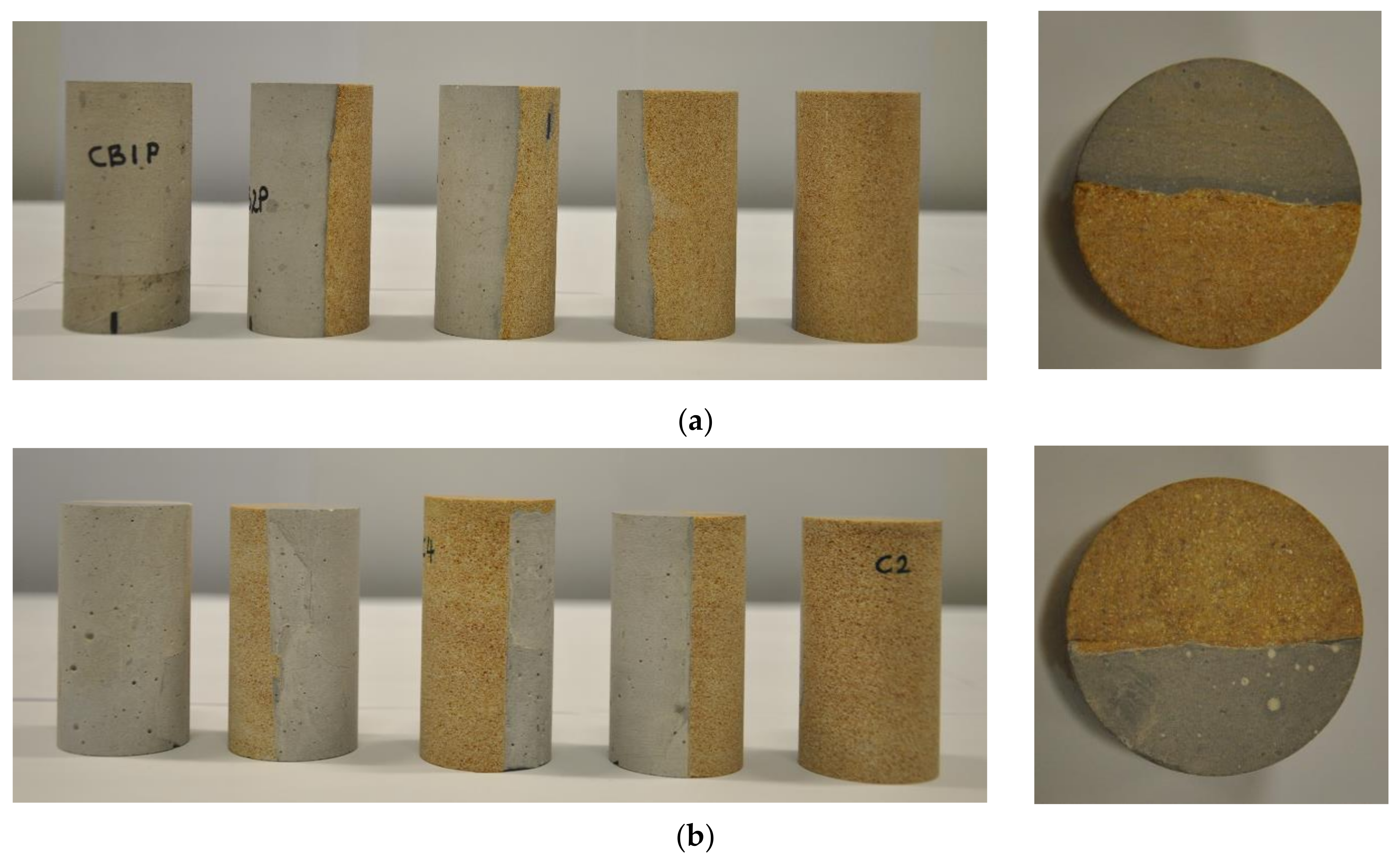
2.1. Cement–Reservoir Rock Composite Samples and Fluid Preparation

Sandstone samples collected from Cayton Bay, North Yorkshire, were used to represent the reservoir rock. This is a yellowish sandstone of the Osgodby Formation from the Callovian age of the Jurassic period. The formation was found to be fine- to medium-grained calcareous sandstone and clean at most levels, but iron-stained at others, the latter layers containing small ooliths of iron carbonate (beds of berthierine (chamosite) ooids), calcareous siltstone, and thin limestone. The sample blocks used in this study were of the clean sandstone layers and those less bioturbated with horizontal crustacean burrows (Thalassinoides), which are otherwise abundant.
A number of 38 mm diameter cement–sandstone composite core samples were prepared with a diameter-to-length ratio of 1/2 (Figure 1). API Class G Portland cement with 100 parts cement and 44 parts water was used to prepare the composite core samples [50]. The composite samples were prepared with the bedding planes of sandstone either parallel (samples labelled as CBxP) or perpendicular (samples labelled as Cx) to the cement–sandstone contact in order to investigate directional permeability and chemical-reaction-related effects near the wellbore. The samples had an average grain density of 2.35 g/cm3 and an average weight of approximately 180 g. The porosity, permeability, and mechanical and elastic properties of the cement–reservoir composite samples were measured before and after exposure to CO2-rich brine at 25 MPa and 90 °C to assess the effect of HPHT reactions on flow properties and mechanical behaviour. The porosity was measured using a helium pycnometer. Permeability to nitrogen (N2) was measured in a modified Hassler cell under 2.4 MPa confinement to prevent nitrogen bypass. Multistage triaxial compression tests at different confinement levels (1.5, 5.0, 8.0, and 14.0 MPa, before finally being brought to failure at 18.0 MPa confinement) were carried out for the stress–strain–permeability characterisation of the samples in a four-column, 2000 kN capacity servo-controlled rock-testing machine (Figure 2) following the ISRM’s suggested methods [51,52]. Destructive testing of the composite core samples could only be performed either before or after the HPHT reactor experiments. Those samples, which were tested for mechanical and elastic properties before the HPHT reactor experiments, were therefore used as reference samples to compare their properties with those of the samples tested after long-term HPHT treatment. The mean petrophysical and geomechanical properties of all the core samples tested before HPHT treatment are presented in Table 2.
The selection of the brine’s composition was based on the typical brine composition (including brines found in the North Sea), which includes Na+, K+, Mg2+, Ca2+, Sr2+, Ba2+, Fe3+, Cl, and SO42− [53]. A low-salinity brine (10,285 ppm) with major ions including Na+, K+, Mg2+, Ca2+, Sr2+, and Ba2+ was synthesised by dissolving NaCl, KCl, MgCl2·6H2O, CaCl2·6H2O, and SrCl2·6H2O in 1 L of Millipore water. Table 3 shows the concentration of the prepared synthetic brine (unreacted brine) used in the reactor experiments described here [54].

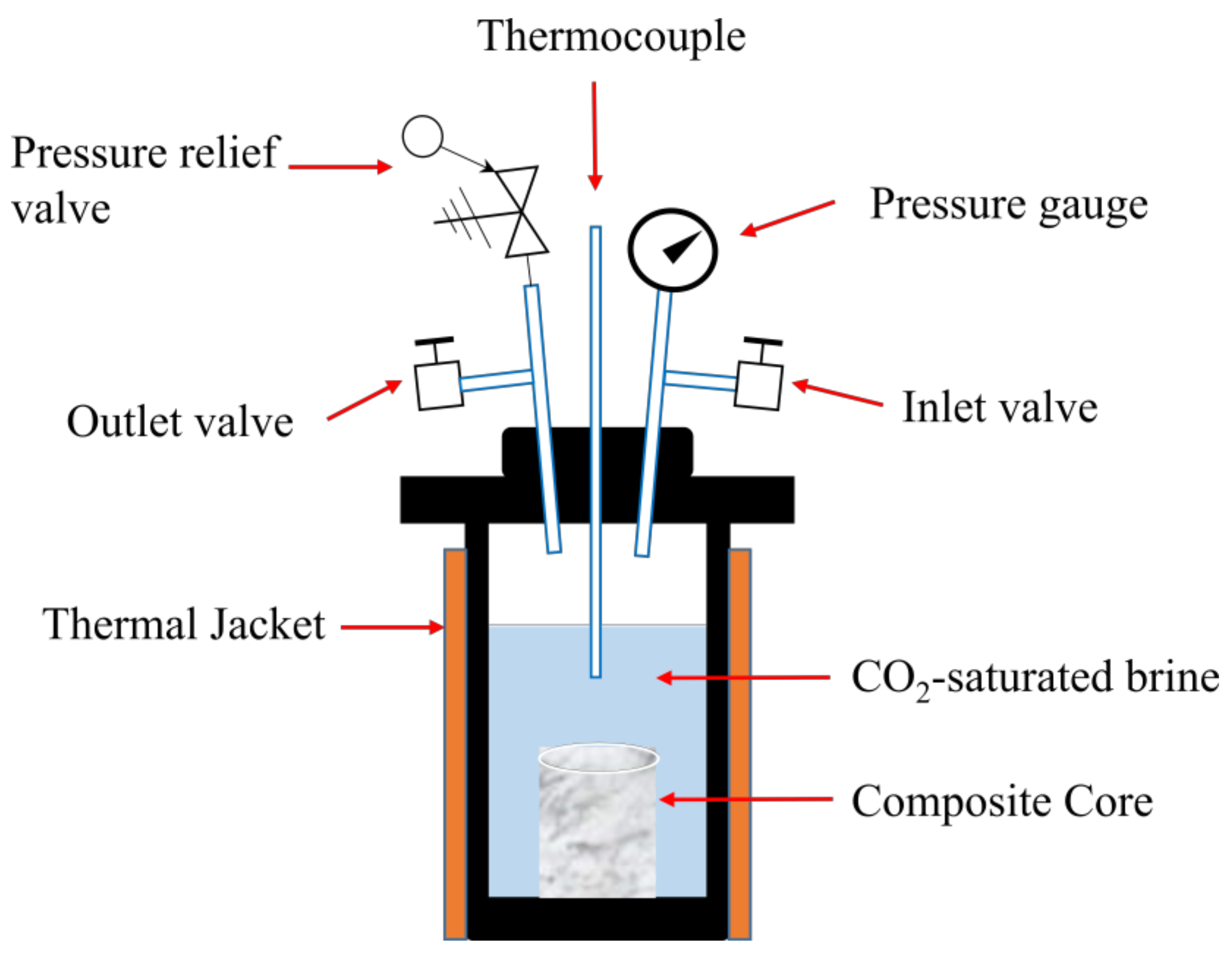
2.2. Hydrothermal Testing Experiments

The long-term CO2–brine and cement–reservoir rock interaction experiments were performed using a set of high-pressure and high-temperature reactors constructed by the authors. Each reactor, as illustrated in Figure 3, consisted of a vessel, inlet and outlet valves, a pressure relief valve (PRV), a pressure gauge, and a thermocouple. The inside of the hydrothermal reactors was fitted with corrosion-resistant polytetrafluoroethylene (PTFE) liners to avoid any possible corrosion during the course of experiments. A leak test with duration of one to two months was carried out prior to each experiment. After the leak test, a composite sample and the synthetic brine were introduced into the vessel, and the reactor was sealed and heated gradually until it reached the target temperature. Supercritical CO2 was then injected and maintained at the target value of 25 MPa. During the experiment, the pressure and temperature were monitored and controlled to avoid any abrupt pressure loss or temperature variation. Once the experiment was finished, the reactor was first cooled down gradually to ambient conditions (20–25 °C). Subsequently, the reactor pressure was slowly reduced to the atmospheric pressure, and the reacted sample and brine were taken for a series of different analyses.

3. Results and Discussion

A reference (baseline) characterisation was performed on some of the unreacted composite core samples by measuring their porosity, permeability, and mechanical and elastic properties, as well as using SEM–EDX, XRD, and X-ray µ-CT. The composites, which had not been through destructive testing, were then exposed to CO2-rich brine for two periods of 3 and 11 months using the HPHT reactors to mimic typical downhole environments (25 MPa and 90 °C). Various analytical methods were used to investigate the chemical and physical effects of CO2-rich brine on the cement and the cement–sandstone interfaces. ICP analysis showed a similar trend in the variation of ion concentration for the majority of the composite samples. The results of the chemical and mineralogical analyses of the HPHT-treated samples were consistent for all the composite samples tested; therefore, we used the composite sample CB1P to illustrate those observations made. However, depending on the bedding plane directionality of the samples tested, the changes in the flow and mechanical properties of different samples revealed important information relevant to long-term behaviour at the wellbore. These will be discussed using data from samples prepared in both orientations. Figure 4 presents examples for each of the two sets of samples tested.

3.1. Inductively Coupled Plasma Optical Emission Spectrometry (ICP-OES)

ICP-OES analysis of the synthesised unreacted brine sample was performed to obtain a baseline for the ion concentration in the solution before running the hydrothermal experiment. ICP-OES analyses were also conducted for all the solution samples after 3 and 11 months to determine any possible changes in the ion concentration.
Table 4 presents the changes in ion concentration of the reacted brine. Figure S1 in the Supplementary Materials compares the variations in ion concentrations over 3 and 11 months for two groups of samples, CB1P&CB3P and C1&C3, respectively. Generally, similar trends were observed in the variation of ion concentrations for all composite samples tested. Ba, Ca, Mg, and Sr were consumed in the early stages (within 3 months); however, they redissolved in the solution later, with the exception of Mg, which continued to decrease with time. The concentrations of Fe, S, and Si (not present in the prepared brine) increased with time, especially at the later stage of the experiment (11 months).

3.2. XRD Analysis

Sections from the top of composite samples were used for XRD analysis after exposure to CO2-rich brine for 11 months.

3.2.1. Cement

The original composition of the cement before exposure to CO2-rich brine was portlandite (Ca(OH)2), ettringite (Ca6Al2(SO4)3(OH)12 26H2O), and calcium silicate hydrate (Ca(OH)2SiO2). The XRD analysis of the cement portion of a composite sample after exposure to CO2-rich brine revealed that the phases were portlandite (Ca(OH)2), hydrotalcite (Mg6Al2CO3(OH)16 4(H2O)), hydroandradite (Ca3Fe2(SiO4)3−x(OH)4X), and potassium phosphate (K3PO4), as well as carbonates in the forms of calcite and aragonite (CaCO3). Clearly, dissolution of most of the cement phases presented in Table 1 occurred during the experiments.

3.2.2. Sandstone

The unreacted sandstone sample was mainly composed of quartz (SiO2), with small amounts of K-feldspar (KAlSi3O8) and kaolinite (Al2Si2O5(OH)4). The XRD analysis of the sandstone portion of the composite sample after the hydrothermal experiment did not show any significant changes in composition, with the exception of a weak peak assigned to calcite (CaCO3).

3.3. SEM–EDX Analysis

A series of SEM–EDX analyses was performed on thin sections taken from the top of composite samples after exposure to CO2-saturated brine for 11 months to investigate the composition changes in different parts of the sample, including the cement, sandstone, and cement–sandstone interface. No significant change was observed in the sandstone portion of the sample, and therefore, the focus of the following subsections is on cement and the interface of cement and sandstone. The SEM–EDX results of only one composite sample will be presented here, as similar observations were made for the other analysed samples.

3.3.1. Cement

The outer cement surface of the CB1P composite sample after exposure to CO2-saturated brine for 11 months displayed a crust of variable thickness presenting a different composition from the original cement. Elemental maps (Figure 5) showed enrichment in K, Fe, and Na (Figure 5c–e) within the crust, and depletion in S, Ca, Mg, and Cl (Figure 5b,f–h). This observation confirmed the findings of previous research [1,22,27]. Moreover, enrichment of Cl at the boundary between the crust and unaltered cement was also observed (Figure 5b).
Void (pore) spaces and hairline fractures within the cement exhibited darker halos (Figure S2a,e in the Supplementary Materials), and analysis of the elemental maps showed depletion in Ca and oxygen, with an increase in C (Figure S2). The differences could be due to higher porosity around bubbles and fractures. Other elements displayed little variation between cement and darker halos, unlike that seen at the alteration crusts.
A recent study by Mito et al. [55] simulated a wellbore section using a concentric arrangement of a carbon steel bar (centre), Portland cement (Class A), and a sandstone ring (outer layer), and performed batch experiments at 50 °C and 10 MPa of CO2 pressure. The composite samples were exposed to supercritical CO2, CO2-saturated brine, or both CO2 and CO2-saturated brine. Cement carbonation to a depth of few millimetres was observed. However, due to fast precipitation of CaCO3 around the cement–rock interface, no further alteration in the interior of the cement was observed after 56 days. As the composition of brine used in this study was different from that used by Mito et al., a different behaviour in the change of sampled water composition was observed in the early stages. However, there were similarities in the general trend of ion-concentration changes. The Ca concentration in brine increased over time in 56 days in their experiments, and a similar trend was observed in the current experiments from 3 to 11 months of exposure to CO2-rich brine.
Carroll et al. [56] performed batch experiments to investigate the interaction of CO2 with cement–sandstone (or shale)–brine at reservoir conditions. They observed rapid carbonation in the cement as supercritical CO2 was injected into the brine. The concentration of Ca decreased while dissolved Mg and Si increased, and a low concentration of Al was observed. Although the cement carbonation was the dominant reaction in their experiment, chemical activities also were observed in the sandstone, as concentration of Fe increased when the sandstone began reacting with the CO2-rich brine. The assemblage of cement–sandstone in the current work was not the same as the one used in Carroll et al.’s work, and therefore, we did not expect to observe similar behaviour.

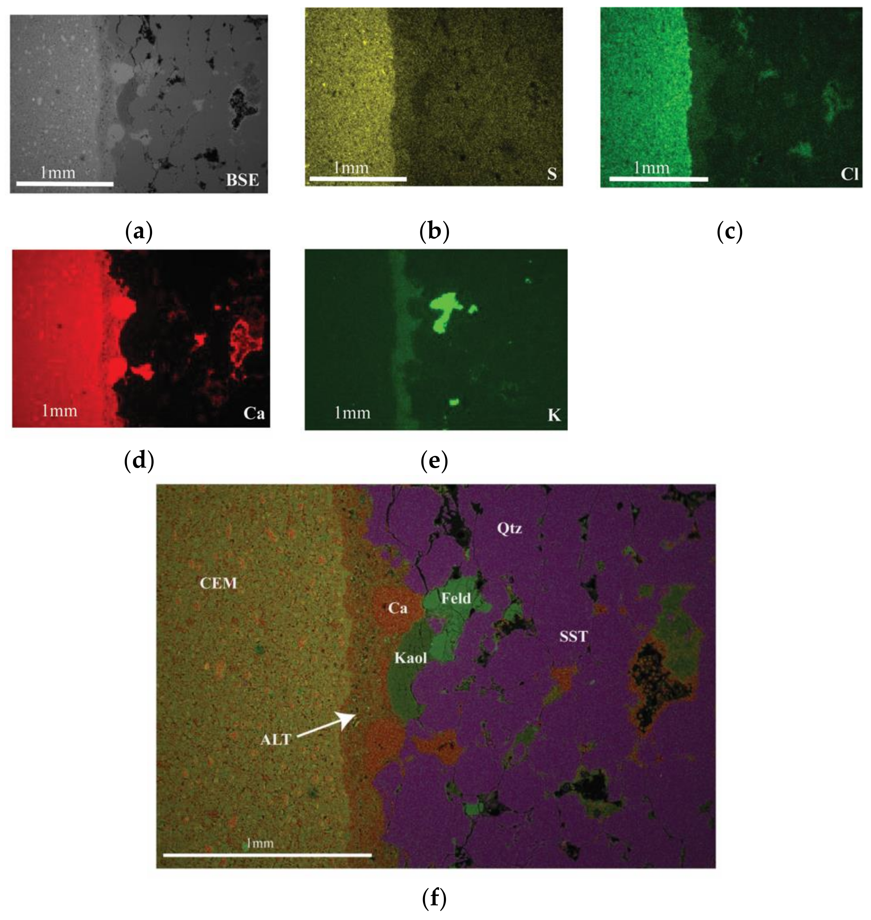
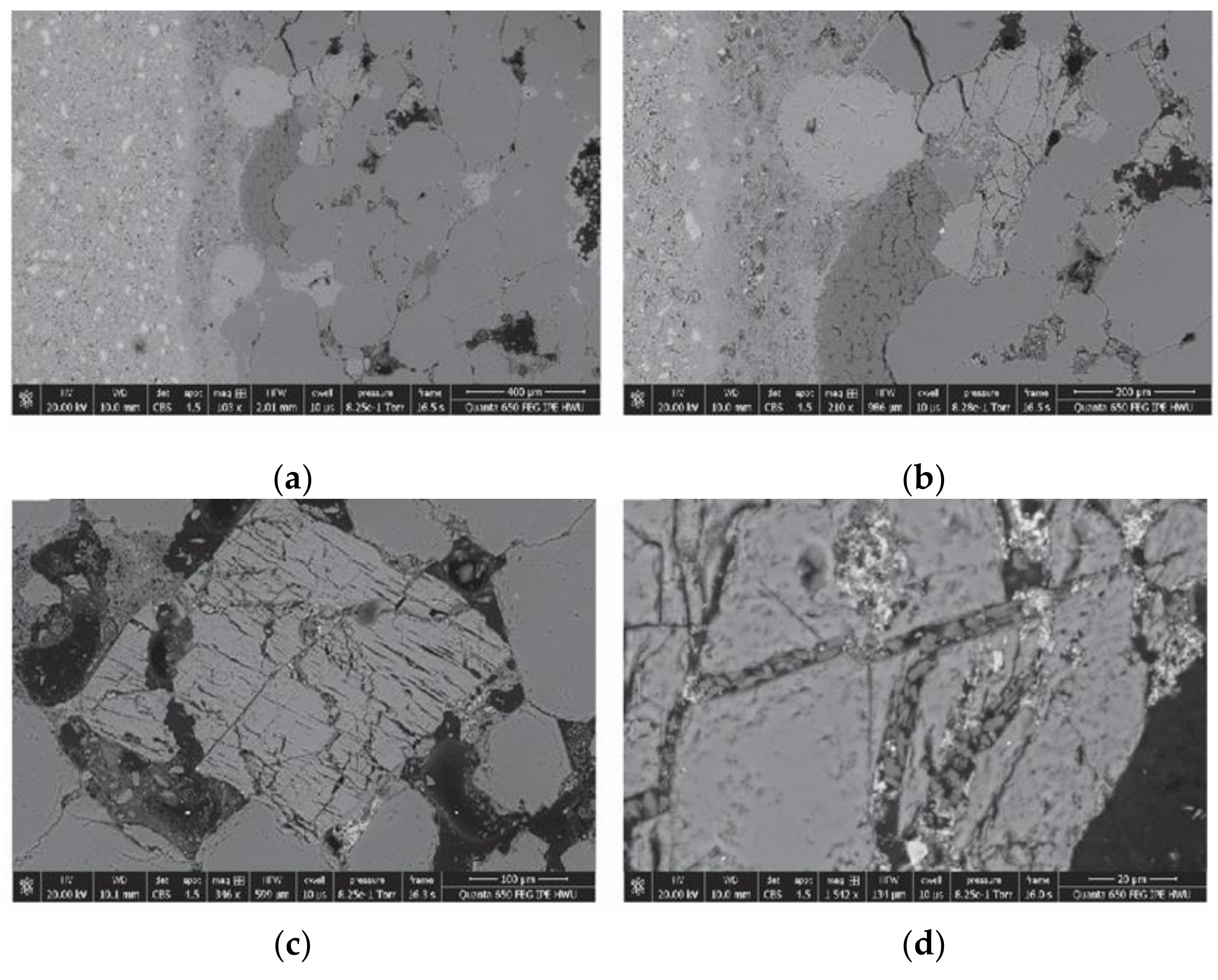
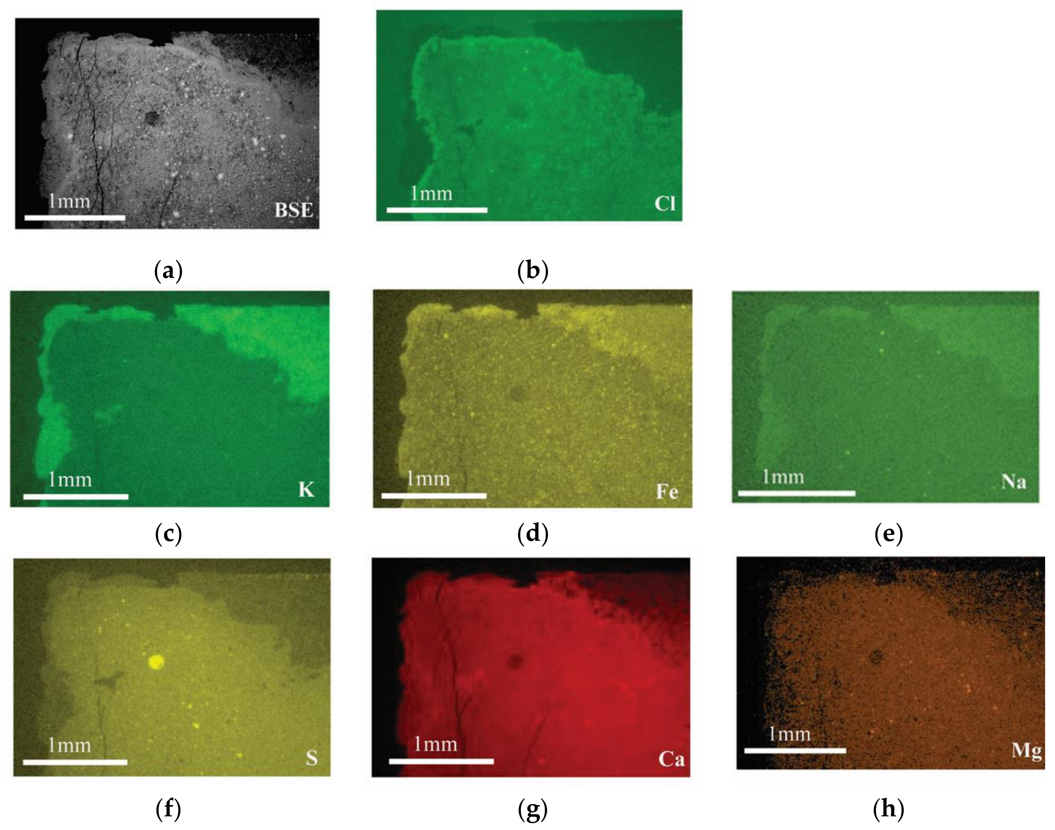
3.3.2. Cement–Sandstone Interface

The boundary between cement and sandstone also exhibited a relative depletion in S, Cl, and Ca, as well as an apparent slight enrichment in K (Figure 6). However, no clear depletion in Mg was observed, nor enrichment in Fe or Na. The zone of depletion was approximately 0.3 mm thick. Figure 6b,c show the relative depletion of S and Cl within the altered cement zone. Figure 6d shows the relative depletion of Ca within the altered cement zone, and the position of Ca-rich pods and pore linings. A relative enrichment in K from the altered cement zone, and the position of K-feldspar (bright area) within the sandstone, is shown in Figure 6e. The phase map (Figure 6f) clearly shows distinct zones of cement (CEM) and sandstone (SST) and between the two altered cement zones (ALT), as well as the occurrence of quartz (Qtz), feldspar (Feld), kaolinite (Kaol), and Ca-rich areas (Ca), which formed pods and thin layers within the altered cement zone, and occasionally lined pores within the sandstone.
This zone of alteration at the interface of the cement and rock differed from that observed on the cement surface by the lack of enrichment in Fe and Na, and did not exhibit an enrichment in Cl at the border between the cement and altered cement. Ca-rich pods occurred within the alteration zone, and lined pore spaces within the sandstone (Figure 6d,f).
The ICP analysis of the brine samples after 11 months indicated an increase in Ca, K, Na, S, Sr, and Fe. This correlated well with the SEM–EDX analysis, which showed a loss of Ca and S from the crust and alteration zone, but not with an observed enrichment in K, Na, and Fe.

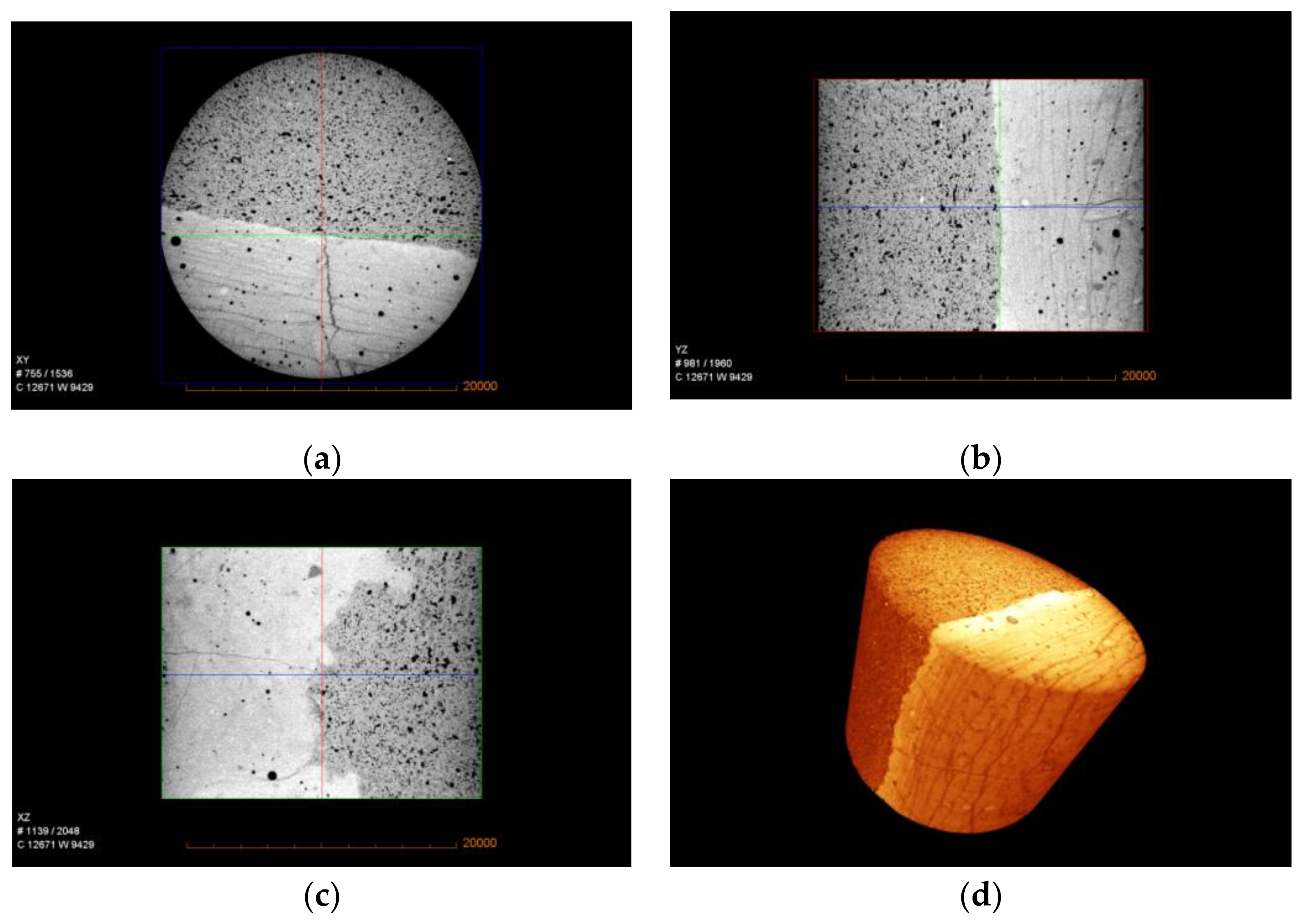
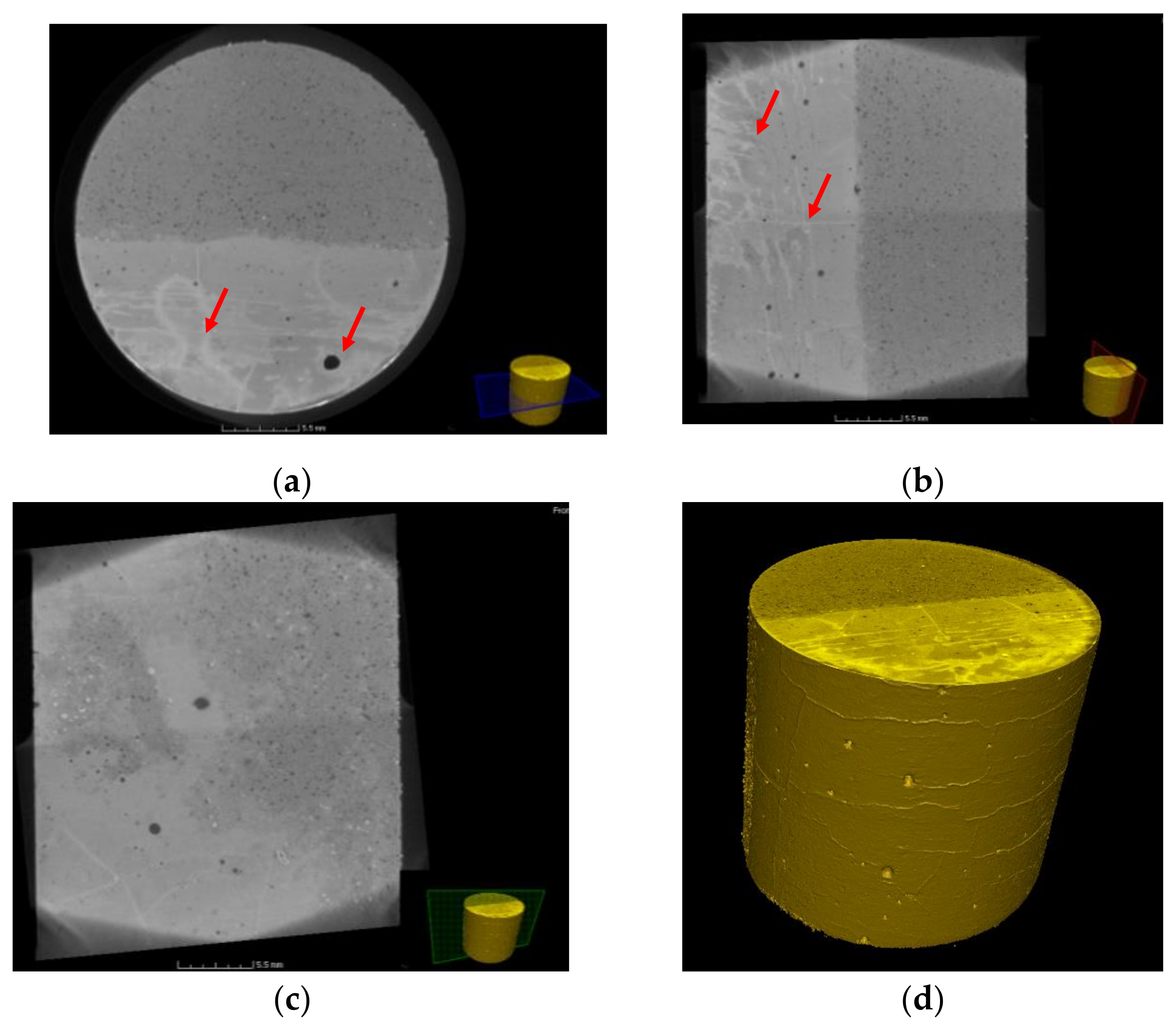
3.4. X-Ray µ-CT Image Analysis

An X-ray μ-CT image analysis was used to determine the effects of physical and chemical processes such as dissolution and precipitation on the composite samples. This was possible through scanning the composite samples using a μ-CT scanner both before and after exposure to the CO2-rich brine. Similar to Section 3.3, the image analysis of one sample is presented here. Figure 7 shows the reconstructed 3D volume and 2D cross-sections of the cement–sandstone composite sample CB1P before being exposed to CO2-rich brine. Different-sized void spaces, as well as hairline fractures (cracks), can be seen in the cement.
Figure 8 shows the reconstructed 3D volume and 2D cross-sections of the same composite sample (CB1P) after being exposed to CO2-rich brine for 11 months at 25 MPa and 90 °C. The 2D images in Figure 7 and Figure 8 represent different positions in the sample, and therefore are not comparable in terms of exact features; however, the invasion of CO2-rich brine into the cement part of the sample is clearly demonstrated in Figure 8 (red arrows). The changes in grey-scale within the cement showed how far the solution diffused, which paths were preferred, and possible dissolution and precipitation of minerals during the experiment. Hairline fractures, due to their high permeability, controlled the invasion path of the solution into the sample, particularly in the cement section. As fractures provided CO2-rich brine with easier access to some areas in the cement, dissolution mainly occurred where fractures were mostly populated. The X-ray μ-CT images showed that the interface between cement and sandstone was still intact after the HPHT experiments.
Figures S3 and S4 (in the Supplementary Materials) compare two large void spaces in the cement section (from different cross-sections), where the former shows a void space connected with a fracture, and the latter shows an isolated void space with no connection to any fracture. Precipitation of new minerals can be seen in the void space (red circles) connected to the fractures as CO2-saturation solution could pass through; however, no evidence of any precipitation reaction could be detected in the isolated void space.
It can be seen in Figures S3 and S4 that the hairline fractures also provided a flow path to the solution to reach the cement–sandstone interface. Both dissolution and precipitation of species at the interface of the cement–sandstone could be detected; these were also found in the SEM–EDX analysis.

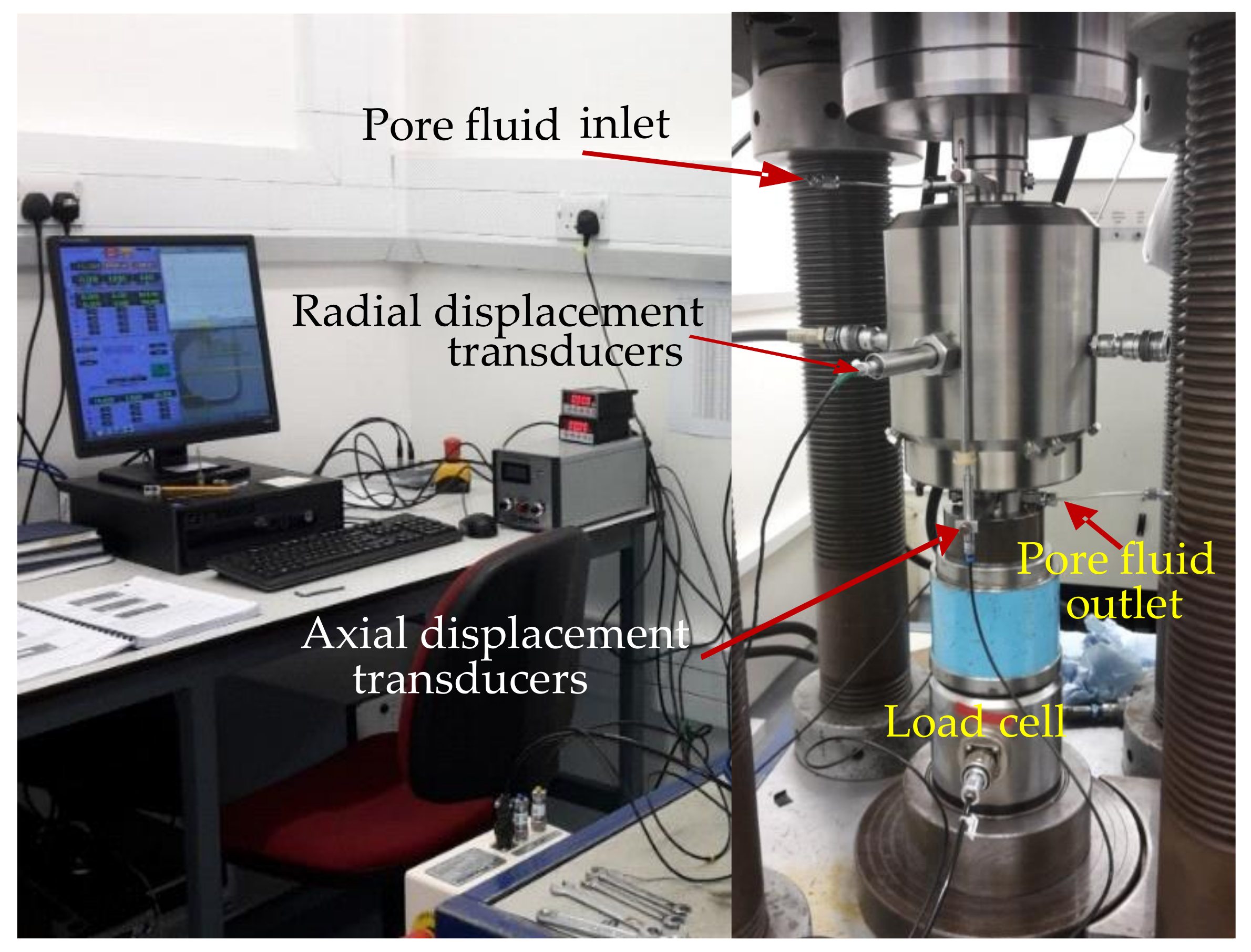
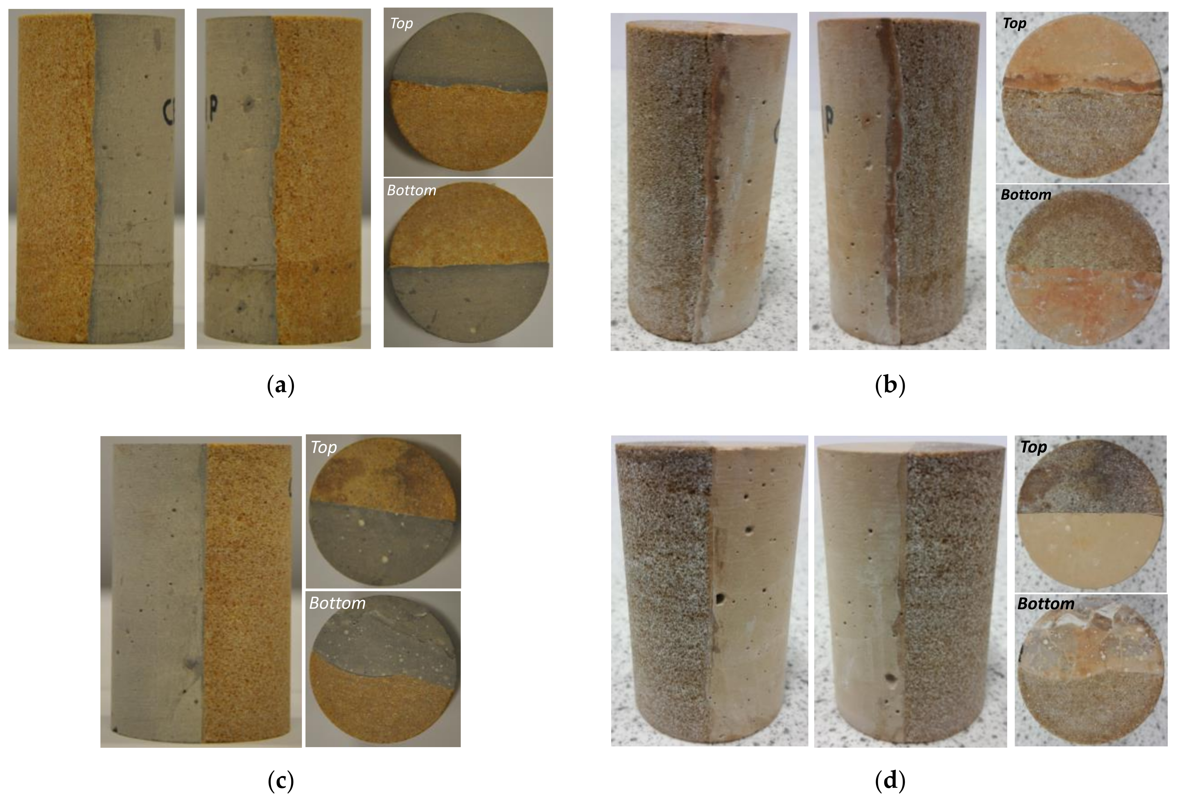
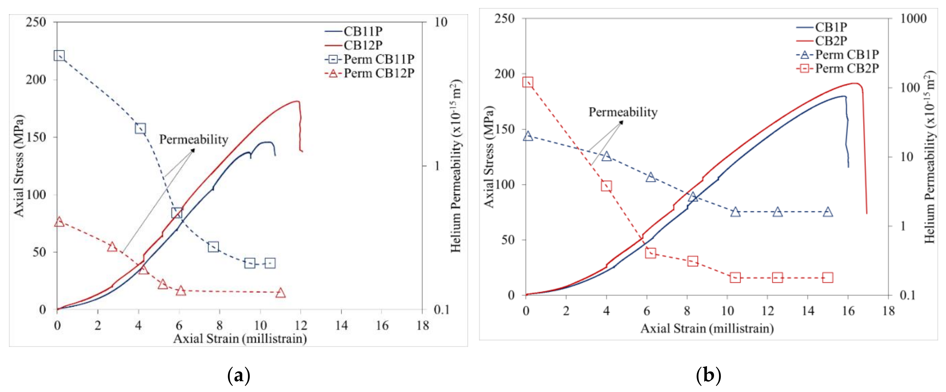
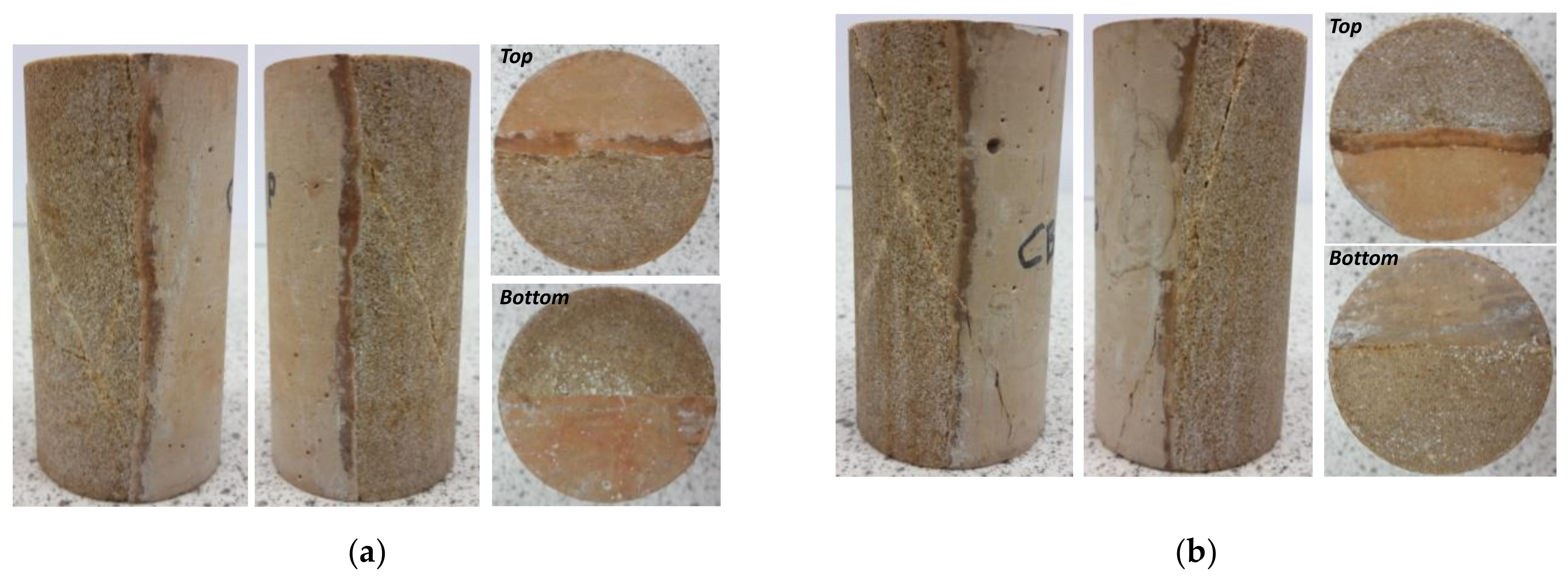
3.5. Changes in Petrophysical and Geomechanical Properties of the Cement–Sandstone Composite Samples

The composite core samples were tested for their petrophysical and mechanical properties before and after being exposed to CO2-rich brine in the HPHT reactors, and possible changes in these properties were evaluated. Figure 9 presents and compares the baseline (before HPHT experiment) stress–strain–permeability behaviour of two different cement–sandstone composite samples, CB11P and CB12P, with that of two other composite samples, CB1P and CB2P, after 11 months of treatment with CO2-rich brine. Figure 10 shows HPHT-treated composite samples CB1P (also shown in Figure 4b after HPHT treatment, but before mechanical testing) and CB2P after multistage stress–strain–permeability testing. Both samples displayed a typical shear failure pattern after being axially loaded to failure at 18.0 MPa confinement stress as illustrated in Figure 9b.
Table 5 presents the baseline Hassler cell porosities and permeabilities of the cement–sandstone composite samples, and compares these with their porosities, permeabilities, and mechanical properties after 11 months of exposure to CO2-rich brine. As Table 5 illustrates, although there was no significant change in the porosities of the treated composites, their permeabilities increased by up to an order of magnitude after 11 months. As expected, the samples, which were prepared using sandstone with bedding planes aligned perpendicular to N2 flow during the permeability measurements, began with much lower baseline permeabilities, and the increases in their permeabilities were relatively less pronounced (Table 5). The stress-dependent changes in the permeability of the composite samples shown in Figure 9 were measured during the multistage triaxial tests at each confinement level to represent permeabilities at different reservoir depths. These values have also shown an order of magnitude difference between the pre- and post-treatment permeabilities in general, showing reduction by up to two orders of magnitude for the post-treatment samples.
The Young’s modulus of the composite samples was reduced significantly (from a mean E value of 20.47 GPa to 15.25 GPa) after long-term exposure to CO2-rich brine, displaying lower stiffness overall. The Poisson’s ratio for the treated samples also was reduced from a mean υ value of 0.31 to 0.27. Note that mechanical-properties testing is destructive; therefore, the results obtained from triaxial testing of the pretreatment samples served as the baseline values. The baseline Young’s modulus and Poisson’s ratio values shown in Table 5 are therefore the mean values taken from Table 2 for comparison.
Contrary to initial expectations, the geochemical reactions that took place during 11 months of HPHT exposure to CO2-rich brine did not affect the mechanical strength or permeability of the cement–sandstone interface itself. As illustrated in Figure 4b,d and Figure 10, it was interesting to note that the well-bonded cement–sandstone interfaces in all the composite samples were not weakened or debonded during 11 months of HPHT treatment, and remained intact even after the samples were brought to failure under triaxial loading. This suggests that well-bonded and plugged cement–reservoir rock contact zones in CO2-storage wellbores may not, in the long term, create a permeable leakage pathway unless these are already mechanically failed/debonded under variable stress and pressure conditions experienced during hydrocarbon production and/or CO2 injection periods earlier.
Further analysis of the experimental data showed that the changes in overall permeability of the composite samples could be attributed to the increase in the permeability of the sandstone component in the main, rather than the cement or the cement–sandstone interface. As shown in Figure 4 and Figure 10, the permeability contrast between the cement and the sandstone created the conditions for deposition of materials that were mobilised through the reactions between the brine and the samples. It was perceived that the brine solution, which encountered minerals unstable in its presence, dissolved and almost simultaneously exchanged them for new minerals that were preferentially deposited along surfaces where there was a significant permeability contrast, as was the case along the cement and sandstone interface. As indicated in Table 4, more active chemical reactions occurred during the early stages of the experiment.
Considering the mineralogy of the samples, within the sandstone portion, the feldspars were the less-stable minerals (Figure 11), where the grain boundaries became less sharp, and newly formed flow paths were created along the feldspar mineral grain cleat. The sandstone permeability increased as a result. In the samples in which the cement was in contact with sandstone aligned perpendicular to the bedding, the reactions and pathways were more limited. Therefore, the increase in the initially low permeability of the composite samples was less pronounced.
Within the cement, which was far less permeable (Table 2), reactions occurred more readily on the surface of the core and along the contact with the sandstone, enabled by the substantially higher permeability of the rock. Therefore, the alteration zone was wider for the samples in which the bedding was parallel to the cement–sandstone interface, and substantially narrower for the samples with a perpendicular bedding (Figure 4b,d). The SEM images indicated the depletion in Ca within the cement (from reaction of the carbonate minerals with the fluid) and its mobilisation. Due to the permeability contrast between the cement and the sandstone, the fluid flow became stagnant, and replacement reactions took place within the cement. The new less-dense and smaller-grain-size mineral phases (kaolinite) were deposited and filled the space between the sandstone and the cement, further reducing the permeability of the contact between the cement and sandstone.

4. Conclusions

The aim of this study was to understand the interactions between CO2-rich brine and cement–reservoir rock, and to evaluate the integrity of wellbore cement and the interface between cement and the reservoir rock. In order to achieve this, it was critical to understand the relationship between the carbonation and dissolution mechanisms and the parameters that influenced the mechanical integrity of the cement–reservoir rock system. A wide range of laboratory techniques was used for assessing the chemical, petrophysical, and mechanical impacts of CO2–brine on the cement–reservoir rock system.
ICP-OES, XRD, SEM–EDX, and X-ray μ-CT showed degradation of the cement due to chemical reactions as a result of being exposed to CO2-saturated brine. SEM–EDX and X-ray μ-CT suggested that the alteration depth in the cement, which was controlled by a diffusion process, could be affected by the presence of hairline fractures. Cracks and fractures provided high permeability pathways to CO2-rich brine, which increased the penetration depth and influenced the dissolution and precipitation in the cement.
Precipitation or carbonation increased mechanical strength and decreased permeability in the cement, while dissolution decreased mechanical strength and increased permeability primarily within the sandstone. Our observations confirmed the findings of previous research [31,42,43] that the dissolution process in fact increased the permeability of the samples, while at the same time, lowered their mechanical and elastic properties. The relationship between the geomechanical changes and their impact on wellbore integrity is complicated and depends on several parameters, including the acidity, the brine composition, the confining pressure, the pore pressure, and the residence time [4]. Although cement degradation may have a negative impact on the wellbore integrity, the increasing compressibility due to calcium leaching may result in compression of the affected area and close any escape pathway in the cement [4,57].
Although no considerable changes in porosity were observed, permeability of composite samples increased by an order of magnitude after exposure to CO2-rich brine. Small new pores (void spaces), which may not have been connected, were generated as a result of dissolution in the cement half of the composite samples. However, most of the hairline fractures in the cement were filled due to precipitation. Therefore, the overall effect of the dissolution and precipitation processes was more pronounced on the permeability and less on the porosity of the cement. Geomechanical analysis showed significant reduction in both the Young’s modulus and the Poisson’s ratio of the composite samples, while the overall mechanical strength of the samples increased slightly.
After long-term HPHT treatment of the composite samples, an order of magnitude increase in the mean permeabilities of the samples prepared with the sandstone bedding planes either parallel and perpendicular to the cement/rock contact was observed. The analysis of the data obtained from all the experiments confirmed that this was mainly due to an increase in the permeability of the sandstone component of the composite samples, rather than the cement or the cement–sandstone interface. Furthermore, both the initial and post-HPHT treatment permeabilities of the perpendicular samples, which were representative of the primary fluid flow direction in the reservoir rock at the wellbore, were relatively small, and an order of magnitude smaller than those of the parallel samples. These observations suggested that long-term chemical reactions that take place at the wellbore are not likely to affect upward mobility of CO2 significantly along well-bonded cement–reservoir rock interfaces.
The experiments we carried out suggested that well-bonded and plugged cement–reservoir rock interfaces in CO2-storage reservoirs may not create a permeable leakage pathway unless the interfaces are already mechanically failed/debonded under variable stress and pressure conditions experienced during earlier production/injection periods.

Supplementary Materials

The following are available online at https://www.mdpi.com/article/10.3390/en14165033/s1, Figure S1. Concentration of ions present in the brine at initial conditions, after CO2 injection for 3 months (for samples CB1P and C3) and 11 months (for samples CB3P and C1), Figure S2. Top left corner of CB1P after exposure to CO2–rich brine for 11 months (a) and (e) BSE images, and (b) to (d) and (f) to (h) EDX elemental maps of areas in (a) and (e). (b) and (f) oxygen, (c) and (g) carbon, (d) and (h) calcium, Figure S3. CB1P composite sample after 11 months exposure to CO2-rich brine; precipitation in the void spaces in the red circle where the access of solution was possible through several fractures, Figure S4. CB1P composite sample after 11 months exposure to CO2-rich brine, no significant precipitation in the voids, which are not connected to the fractures.

Author Contributions

Conceptualization, M.M.-V., A.K. and S.D.; formal analysis, A.J., M.H.M., H.A., N.M.F., J.B., M.R., M.M.-V., A.K. and S.D.; funding acquisition, M.M.-V., A.K. and S.D.; investigation, A.J., Q.L., M.H.M., H.A., N.M.F. and J.B.; methodology, Q.L., M.M.-V., A.K. and S.D.; project administration, M.M.-V., A.K. and S.D.; supervision, M.M.-V., A.K. and S.D.; visualization, A.J., M.H.M., H.A. and J.B.; writing—original draft, A.J.; writing—review and editing, A.J., J.B., M.R., M.M.-V., A.K. and S.D. All authors have read and agreed to the published version of the manuscript.

Funding

This research was carried out as part of the UK Research Councils’ Energy Programme-funded consortium project “CO2 injection and storage—short- and long-term behaviour at different spatial scales” (Grant Reference: EP/K035967/1).

Institutional Review Board Statement

Not applicable.

Informed Consent Statement

Not applicable.

Data Availability Statement

The data acquired during this study can be made available upon request from the corresponding authors.

Acknowledgments

The authors would like to thank the Engineering and Physical Sciences Research Council for the funding provided. Financial support received from the Robert M. Buchan Chair in Sustainable Energy Engineering at Heriot-Watt University is gratefully acknowledged. The authors also thank Dubravka Pokrajac of the University of Aberdeen for the micro-CT imaging.

Conflicts of Interest

The authors declare no conflict of interest.

Abbreviations

2DTwo-Dimensional
3DThree-Dimensional
CCUSCarbon dioxide Capture, Utilisation, and Storage
X-ray µ-CTX-ray Microcomputed Tomography
XRDX-ray Diffraction
SEM–EDXScanning Electron Microscopy–Energy-Dispersive X-ray
ICPInductively Coupled Plasma
ICP-OESInductively Coupled Plasma-Optical Emission Spectrometry
HPHTHigh-Pressure and High-Temperature
PRVPressure-Relief Valve
PTFEPolytetrafluoroethylene
BSEBackscattered Electron
CEMCement
SSTSandstone
ALTAltered cement zones
QtzQuartz
FeldFeldspar
KaolKaolinite

References

  1. Zhang, M.; Bachu, S. Review of integrity of existing wells in relation to CO2 geological storage: What do we know? Int. J. Greenh. Gas Control 2011, 5, 826–840. [Google Scholar] [CrossRef]
  2. Iyer, J.; Walsh, S.D.C.; Hao, Y.; Carroll, S.A. Assessment of two-phase flow on the chemical alteration and sealing of leakage pathways in cemented wellbores. Int. J. Greenh. Gas Control 2018, 69, 72–80. [Google Scholar] [CrossRef]
  3. Onishi, T.; Nguyen, M.C.; Carey, J.W.; Will, B.; Zaluski, W.; Bowen, D.W.; Devault, B.C.; Duguid, A.; Zhou, Q.; Fairweather, S.H.; et al. Potential CO2 and brine leakage through wellbore pathways for geologic CO2 sequestration using the National Risk Assessment Partnership tools: Application to the Big Sky Regional Partnership. Int. J. Greenh. Gas Control 2019, 81, 44–65. [Google Scholar] [CrossRef]
  4. Bagheri, M.; Shariatipour, S.M.; Ganjian, E. A Review of oil well cement alteration in CO2-rich environments. Constr. Build. Mater. 2018, 186, 946–968. [Google Scholar] [CrossRef]
  5. Watson, T.L.; Bachu, S. Evaluation of the potential for gas and CO2 leakage along wellbores. SPE Drill. Complet. 2009, 24, 115–126. [Google Scholar] [CrossRef] [Green Version]
  6. Gasda, S.E.; Bachu, S.; Celia, M.A. Spatial characterization of the location of potentially leaky wells penetrating a deep saline aquifer in a mature sedimentary basin. Environ. Geol. 2004, 46, 707–720. [Google Scholar] [CrossRef]
  7. Celia, M.A.; Bachu, S.; Nordbotten, J.M.; Gasda, S.E.; Dahle, H.K. Quantitative estimation of CO2 leakage from geological storage: Analytical models, numerical models, and data needs. In Proceedings of the 7th International Conference Greenhouse Gas Control Technologies, Vancouver, BC, Canada, 5–9 September 2004; pp. 663–671. [Google Scholar]
  8. Dalla Vecchia, F.; dos Santos, V.H.J.M.; Schütz, M.K.; Ponzi, G.G.D.; de Guimarães e Stepanha, A.S.; de Fraga Malfatti, C.; da Costa, E.M. Wellbore integrity in a saline aquifer: Experimental steel-cement interface degradation under supercritical CO2 conditions representative of Brazil’s Parana basin. Int. J. Greenh. Gas Control 2020, 98, 103077. [Google Scholar] [CrossRef]
  9. Sweatman, R.E.; Marsic, S.D.; McColpin, G.R. Advancements in technology and process approach reduce cost and increase performance of CO2-flow monitoring and remediation. In Proceedings of the SPE International Conference CO2 Capture, Storage and Utilization, Society of Petroleum Engineers, New Orleans, LA, USA, 10–12 November 2010; Volume 20. [Google Scholar] [CrossRef]
  10. Druckenmiller, M.L.; Maroto-Valer, M.M. Carbon sequestration using brine of adjusted pH to form mineral carbonates. Fuel Process. Technol. 2005, 86, 1599–1614. [Google Scholar] [CrossRef]
  11. Brunet, J.-P.L.; Li, L.; Karpyn, Z.T.; Kutchko, B.G.; Strazisar, B.; Bromhal, G. Dynamic evolution of cement composition and transport properties under conditions relevant to geological carbon sequestration. Energy Fuels 2013, 27, 4208–4220. [Google Scholar] [CrossRef]
  12. Carey, J.W. Geochemistry of wellbore integrity in CO2 sequestration: Portland cement-steel-brine-CO2 interactions. Rev. Mineral. Geochem. 2013, 77, 505–539. [Google Scholar] [CrossRef]
  13. Mainguy, M.; Ulm, F.-J. Coupled diffusion-dissolution around a fracture channel: The solute congestion phenomenon. Transp. Porous Media 2001, 45, 479–495. [Google Scholar] [CrossRef]
  14. Kutchko, B.G.; Strazisar, B.R.; Dzombak, D.A.; Lowry, G.V.; Thauiow, N. Degradation of well cement by CO2 under geologic sequestration conditions. Environ. Sci. Technol. 2007, 41, 4787–4792. [Google Scholar] [CrossRef] [PubMed]
  15. Duguid, A.; Scherer, G.W. Degradation of oilwell cement due to exposure to carbonated brine. Int. J. Greenh. Gas Control 2010, 4, 546–560. [Google Scholar] [CrossRef]
  16. Walsh, S.D.C.; Du Frane, W.L.; Mason, H.E.; Carroll, S.A. Permeability of wellbore-cement fractures following degradation, by carbonated brine. Rock Mech. Rock Eng. 2013, 46, 455–464. [Google Scholar] [CrossRef]
  17. Richardson, M.G. Carbonation of Reinforced Concrete: Its Causes and Management; Citis: New York, NY, USA, 1988; 205p. [Google Scholar]
  18. Thomas, M.D.A.; Matthews, J.D. Carbonation of flyash concrete. Mag. Concr. Res. 1992, 44, 217–228. [Google Scholar] [CrossRef]
  19. Loo, Y.H.; Chin, M.S.; Tam, C.T.; Ong, K.C. A carbonation prediction model for acclerated carbonation testing of concrete. Mag. Concr. Res. 1994, 46, 191–200. [Google Scholar] [CrossRef]
  20. Kutchko, B.G.; Strazisar, B.R.; Lowry, G.V.; Dzombak, D.; Thaulow, N. Rate of CO2 attack on hydrated class H well cement under geologic sequestration conditions. Environ. Sci. Technol. 2008, 42, 6237–6242. [Google Scholar] [CrossRef]
  21. Strazisar, B.; Kutchko, B.; Huerta, N. Chemical reactions of wellbore cement under CO2 storage conditions: Effects of cement additives. Energy Procedia 2009, 1, 3603–3607. [Google Scholar] [CrossRef] [Green Version]
  22. Walsh, S.D.C.; Mason, H.E.; Du Frane, W.L.; Carroll, S.A. Experimental calibration of a numerical model describing the alteration of cement/caprock interfaces by carbonated brine. Int. J. Greenh. Gas Control 2014, 22, 176–188. [Google Scholar] [CrossRef]
  23. Carey, J.W.; Svec, R.; Grigg, R.; Lichtner, P.C.; Zhang, J.; Crow, W. Wellbore integrity and CO2-brine flow along the casing-cement microannulus. Energy Procedia 2009, 1, 3609–3615. [Google Scholar] [CrossRef] [Green Version]
  24. Carey, J.W.; Wigand, M.; Chipera, S.J.; WoldeGabriel, G.; Pawar, R.; Lichtner, P.C.; Wehner, S.C.; Raines, M.A.; Guthrie, G.D., Jr. Analysis and performance of oil well cement with 30 years of CO2 exposure from the SACROC Unit, West Texas, USA. Int. J. Greenh. Gas Control 2007, 1, 75–85. [Google Scholar] [CrossRef]
  25. Crow, W.; Carey, J.W.; Gasda, S.; Williams, B.D.; Celia, M. Wellbore integrity analysis of a natural CO2 producer. Int. J. Greenh. Gas Control 2010, 4, 186–197. [Google Scholar] [CrossRef]
  26. Krilov, Z.; Loncaric, B.; Miksa, Z. Investigation of a long-term cement deterioration under a high-temperature, sour gas downhole environment. In Proceedings of the SPE International Symposium on Formation Damage Control, Society of Petroleum Engineers, Lafayette, LA, USA, 24–26 February 2000; Volume 9. [Google Scholar]
  27. Rochelle, C.A.; Milodowski, A.E. Carbonation of borehole seals: Comparing evidence from short-term laboratory experiments and long-term natural analogues. Appl. Geochem. 2013, 30, 161–177. [Google Scholar] [CrossRef] [Green Version]
  28. Taylor, H.F.W. Cement Chemistry, 2nd ed.; Thomas Teldford: London, UK, 1997. [Google Scholar]
  29. Carroll, S.; Carey, J.W.; Dzombak, D.; Huerta, N.J.; Li, L.; Richard, T.; Um, W.; Walsh, S.D.C.; Zhang, L. Review: Role of chemistry, mechanics, and transport on well integrity in CO2 storage environments. Int. J. Greenh. Gas Control 2016, 49, 149–160. [Google Scholar] [CrossRef] [Green Version]
  30. Carey, W.J.; Lichtner, P. Calcium Silicate Hydrate (C-S-H) Solid Solution Model Applied to Cement Degradation Using the Continuum Reactive Transport Model FLOTRAN. In Transport Properties and Concrete Quality: Materials Science of Concrete; Mobasher, B., Skalny, J., Eds.; American Ceramic Society: Columbus, OH, USA; John Wiley & Sons, Inc.: Hoboken, NJ, USA, 2007; Special Volume, pp. 73–106. [Google Scholar]
  31. Mason, H.E.; Du Frane, W.L.; Walsh, S.D.C.; Dai, Z.; Charnvanichborikarn, S.; Carroll, S.A. Chemical and mechanical properties of wellbore cement altered by CO2-rich brine using a multianalytical approach. Environ. Sci. Technol. 2013, 47, 1745–1752. [Google Scholar] [CrossRef]
  32. Carey, W.J.; Svec, R.; Grigg, R.; Zhang, J.; Crow, W. Experimental investigation of wellbore integrity and CO2–brine flow along the casing–cement microannulus. Int. J. Greenh. Gas Control 2010, 4, 272–282. [Google Scholar] [CrossRef]
  33. Wolterbeek, T.K.T.; Hangx, S.J.T.; Spiers, C.J. Effect of CO2-induced reactions on the mechanical behaviour of fractured wellbore cement. Geomech. Energy Environ. 2016, 7, 26–46. [Google Scholar] [CrossRef]
  34. Dusseault, M.B.; Gray, M.N.; Nawrocki, P.A. Why oilwells leak: Cement behaviour and long-term consequences. In Proceedings of the International Oil and Gas Conference and Exhibition in China, Society of Petroleum Engineers, Beijing, China, 7–10 November 2000. [Google Scholar]
  35. Ozyurtkan, M.H.; Radonjic, M. An experimental study of the effect of CO2 rich brine on artificially fractured well-cement. Cem. Concr. Compos. 2014, 45, 201–208. [Google Scholar] [CrossRef]
  36. Liteanu, E.; Spiers, C.J.; Peach, C.J. Failure behaviour wellbore cement in the presence of water and supercritical CO2. Energy Procedia 2009, 1, 3553–3560. [Google Scholar] [CrossRef] [Green Version]
  37. Onan, D.D. Effects of supercritical carbon dioxide on well cements. In Proceedings of the Permian Basin Oil and Gas Recovery Conference, Society of Petroleum Engineers, Midland, TX, USA, 8–9 March 1984; Volume 14. [Google Scholar]
  38. Šauman, Z. Effect of CO2 on porous concrete. Cem. Concr. Res. 1972, 2, 541–549. [Google Scholar] [CrossRef]
  39. Gervais, C.; Garrabrants, A.C.; Sanchez, F.; Barna, R.; Moszkowicz, P.; Kosson, D.S. The effects of carbonation and drying during intermittent leaching on the release of inorganic constituents from a cement-based matrix. Cem. Concr. Res. 2005, 34, 119–131. [Google Scholar] [CrossRef]
  40. Lea, F.M. The Chemistry of Cement and Concrete; Edward Arnold: London, UK, 1970. [Google Scholar]
  41. Robins, N.S.; Milodowski, A.E. Borehole cements and the downhole environment: A review. Q. J. Eng. Geol. Hydrogeol. 1986, 19, 175–181. [Google Scholar] [CrossRef]
  42. Claisse, P.A.; El-Sayad, H.I.; Shaaban, I.G. Permeability and pore volume of carbonated concrete. ACI Mater. J. 1999, 96, 378–381. [Google Scholar]
  43. Chi, J.M.; Huang, R.; Yang, C.C. Effects of carbonation on mechanical properties and durability of concrete using accelerated testing method. J. Mar. Sci. Technol. 2002, 10, 14–20. [Google Scholar]
  44. Boukhelifa, L.; Moroni, N.; James, S.G.; Le Roy-Delage, S.; Thiercelin, M.J.; Lemaire, G. Evaluation of cement systems for oil- and gas-well zonal isolation in a full-scale annular geometry. SPE Drill. Complet. 2005, 20, Paper SPE-87195-PA. [Google Scholar] [CrossRef]
  45. Syed, A.; Shi, J.-Q.; Durucan, S.; Korre, A.; Nash, G. Experimental and numerical investigations into CO2 interactions with well infrastructure and its impact on long term well integrity. Energy Procedia 2014, 63, 5707–5714. [Google Scholar] [CrossRef]
  46. van Eijden, J.; Cornelissen, E.; Ruckert, F.; Wolterbeek, T. Development of experimental equipment and procedures to evaluate zonal isolation and well abandonment materials. In Proceedings of the SPE/IADC Drilling Conference and Exhibition, Society of Petroleum Engineers, The Hague, The Netherlands, 14–16 March 2017. SME/IADC-184640-MS. [Google Scholar] [CrossRef]
  47. Wolterbeek, T.K.T.; Ruckert, F.; van Moorsel, S.G.; Cornelissen, E.K. Reactive transport and permeability evolution in wellbore defects exposed to periodic pulses of CO2-rich water. Int. J. Greenh. Gas Control 2019, 91, 102835. [Google Scholar] [CrossRef]
  48. Rhino, K.; Iyer, J.; Walsh, S.D.C.; Carroll, S.A.; Smith, M.M. Influence of effective stress and transport on mechanical and chemical alteration processes at the Cement-Caprock interface. Int. J. Greenh. Gas Control 2021, 109, 103340. [Google Scholar] [CrossRef]
  49. Jung, H.B.; Kabilan, S.; Carson, J.P.; Kuprat, A.P.; Um, W.; Martin, P.; Michael, D.; Kafentzis, T.; Varga, T.; Stephens, S.; et al. Wellbore cement fracture evolution at the cement–basalt caprock interface during geologic carbon sequestration. Appl. Geochem. 2014, 47, 1–16. [Google Scholar] [CrossRef]
  50. American Petroleum Institute. Specification for Cements and Materials for Well Cementing, 25th ed.; API Spec 10A; American Petroleum Institute (API): Washington, DC, USA, 2019. [Google Scholar]
  51. Kovari, K.; Tisa, A.; Einstein, H.H.; Franklin, J.A. Suggested methods for determining the strength of rock materials in triaxial compression: Revised version. Int. J. Rock Mech. Min. Sci. Geomech. Abstr. 1983, 20, 285–290. [Google Scholar]
  52. Brown, E.T. Rock Characterization, Testing & Monitoring: ISRM Suggested Methods; Pergamon Press: Oxford, UK, 1981. [Google Scholar]
  53. Steal, L. An Investigation of CO2-Brine Interactions Using North Sea Oil Well Data with Respect to Geological Storage of Carbon Dioxide and Enhanced Oil Recovery. Ph.D. Thesis, Heriot-Watt University, Edinburgh, UK, 2017. [Google Scholar]
  54. Farooqui, N.M.; Liu, Q.; Maroto-Valer, M.M.; Hadi Mosleh, M.; Korre, A.; Durucan, S. Understanding CO2-brine-wellbore cement-rock interactions for CO2 storage. Energy Procedia 2017, 114, 5206–5211. [Google Scholar] [CrossRef]
  55. Mito, S.; Xue, Z.; Sato, H. Experimental assessment of well integrity for CO2 geological storage: Batch experimental results on geochemical interactions between a CO2–brine mixture and a sandstone–cement–steel sample. Int. J. Greenh. Gas Control 2015, 39, 420–431. [Google Scholar] [CrossRef]
  56. Carroll, S.A.; McNab, W.W.; Torres, S.C. Experimental study of cement-sandstone/shale-brine-CO2 interactions. Geochem. Trans. 2011, 12, 1–19. [Google Scholar] [CrossRef] [PubMed] [Green Version]
  57. Berkowitz, B. Characterizing flow and transport in fractured geological media: A review. Adv. Water Resour. 2002, 25, 861–884. [Google Scholar] [CrossRef]
Figure 1. Examples of well-bonded cement–sandstone composite samples before the testing programme (samples rotated by 180° for full view): (a) samples with sandstone bedding planes parallel to the cement contact (labelled as CBxP), and (b) samples with sandstone bedding planes perpendicular to the cement contact (labelled as Cx).
Energies 14 05033 g001
Figure 2. Experimental setup for stress–strain–permeability measurements for the 38 mm diameter composite core samples.
Energies 14 05033 g002
Figure 3. Schematic (vertical cross-section) of a typical hydrothermal HPHT vessel used to perform the experiments. The drawing is not to scale.
Energies 14 05033 g003
Figure 4. Cement–sandstone composite samples CB1P (a,b) and C1 (c,d) before and after CO2-rich brine exposure in the HPHT reactor for 11 months, respectively.
Energies 14 05033 g004
Figure 5. Backscatteredelectron (BSE) image and EDX elemental maps from the same area on the top left corner of CB1P after exposure to CO2-rich brine for 11 months: (a) BSE image of the area; (bh) elemental maps for chlorine, potassium, iron, sodium, sulphur, calcium, and magnesium, respectively.
Energies 14 05033 g005
Figure 6. BSE image, EDX elemental maps, and phase map for the interface of cement and sandstone from the same area on CB1P after exposure to CO2-rich brine for 11 months: (a) BSE image of the area; (be) elemental maps for sulphur, chlorine, calcium, and potassium, respectively; (f) phase map.
Energies 14 05033 g006
Figure 7. Reconstructed 3D volume and 2D cross-sections of the unreacted CB1P composite cement–sandstone sample: (a) horizontal cross-section; (b) vertical cross-section perpendicular to the interface plane; (c) vertical cross-section, parallel to the interface plane; (d) reconstructed 3D volume.
Energies 14 05033 g007
Figure 8. Reconstructed 3D volume and 2D cross-sections of the CB1P composite cement–sandstone sample after exposure to CO2-rich brine for 11 months: (a) horizontal cross-section; (b) vertical cross-section perpendicular to the interface plane; (c) vertical cross-section, parallel to the interface plane; (d) reconstructed 3D volume.
Energies 14 05033 g008
Figure 9. Multistage triaxial compression test results comparing the stress–strain–permeability behaviour for (a) two representative composite cement–sandstone samples, CB11P and CB12P (tested to define the baseline properties of the samples), with that of (b) two composite cement–sandstone samples, CB1P and CB2P, after HPHT treatment with CO2-rich brine.
Energies 14 05033 g009
Figure 10. Cement–sandstone composite samples (a) CB1P and (b) CB2P displaying a typical shear failure pattern after being axially loaded to failure at 18.0 MPa confinement stress as illustrated in Figure 9b above. Note that the cement–sandstone interface in both samples remained intact after the samples were brought to failure under triaxial loading.
Energies 14 05033 g010
Figure 11. SEM image of the cement–sandstone interface: (a) a pore filled by secondary carbonate deposition; (bd) feldspar grains within the sandstone portion illustrating varying degrees of alteration.
Energies 14 05033 g011
Table 1. Dissolution of major cement phases in CO2-rich brine.
Cement Phase
Dissolution
Reaction
PortlanditeCa(OH)2 + 2H+ Ca2+ + 2H2O (Ca(OH)2(s) + 2H+ + CO3−2 CaCO3 (s) + 2H2O)
Calcium silicate hydrateCa1.2SiO3.2·2.06H2O + 2.4H+ 1.2Ca2+ + SiO2+3.26H2O
MonosulfateCa4Al2O6(SO4)·12H2O + 12H+ 4Ca2+ + 2Al3+ + SO42− + 18H2O
TrisulfateCa6Al2(SO4)3(OH)12·26H2O + 12H+ 6Ca2+ + 2Al3+ + 3SO42− + 38H2O
Calcium aluminate hydrateCa3Al2(OH)12 + 12H+ 3Ca2+ + 2Al3+ + 12H2O
Table 2. Mean baseline petrophysical and geomechanical properties of the samples used.
Sample TypeHe Porosity
(−)
N2 Permeability
(×10−15 m2)
Young’s
Modulus
(GPa)
Poisson’s Ratio
Cement–sandstone composites0.124.12/0.92 *20.470.31
Sandstone0.0810.3218.960.24
Portland cement0.030.1512.130.36
* Permeability of cement–sandstone composite samples when measured with the flow direction parallel/perpendicular to bedding planes, respectively.
Table 3. Initial brine composition before HPHT experiments.
SpeciesCaKNaMgBaSr
Concentration (ppm)61230354336328154
Table 4. Brine compositions before and after the HPHT experiments.
Composite SampleBaCaKMgNaSSiSrFe
(ppm)
Unreacted brine281612303635433Not detectedNot detected54.0Not detected
CB3P (3 months)18023622429940010
CB4P (3 months)25726052831100020
CB1P (11 months)4365168919617830501247
CB2P (11 months)733017001864942560966
C3 (3 months)36818484544160010
C1 (11 months)627413321166999701026
C2 (11 months)180128821821414101229
Table 5. Comparison of Hassler cell porosities, permeabilities, and mechanical properties of the cement–sandstone composite samples before and after the HPHT experiments.
Sample No.He Porosity (%)N2 Permeability (×10−15 m2)Young’s Modulus (GPa)Poisson’s Ratio
Before HPHT ExperimentAfter HPHT ExperimentBefore HPHT ExperimentAfter HPHT ExperimentAfter HPHT ExperimentAfter HPHT Experiment
CB1P0.100.126.6792.0815.180.29
CB2P0.090.105.1744.2314.620.20
C10.120.110.683.3314.470.33
C20.140.110.937.3016.820.27
Mean baseline mechanical properties before treatment with CO2-rich brine in HPHT reactors (from Table 2)
20.470.31
Publisher’s Note: MDPI stays neutral with regard to jurisdictional claims in published maps and institutional affiliations.

