
Assessment of Hybrid Solvent—Membrane Configurations for Post-Combustion CO2 Capture for Super-Critical Power Plants


Abstract
:1. Introduction
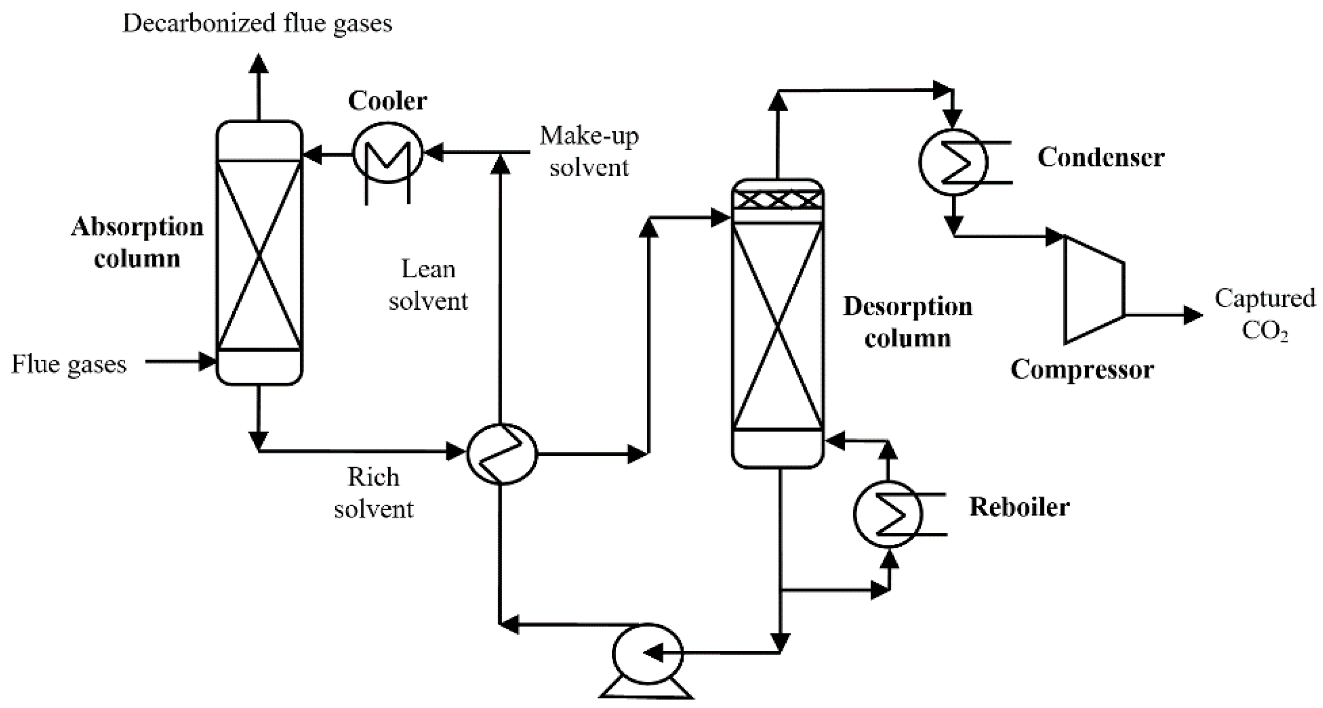
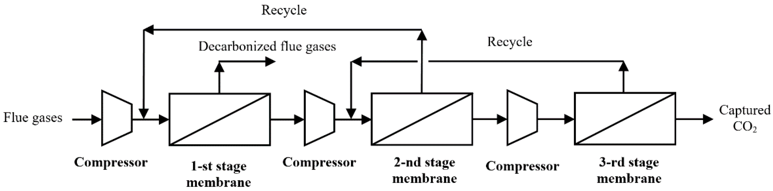
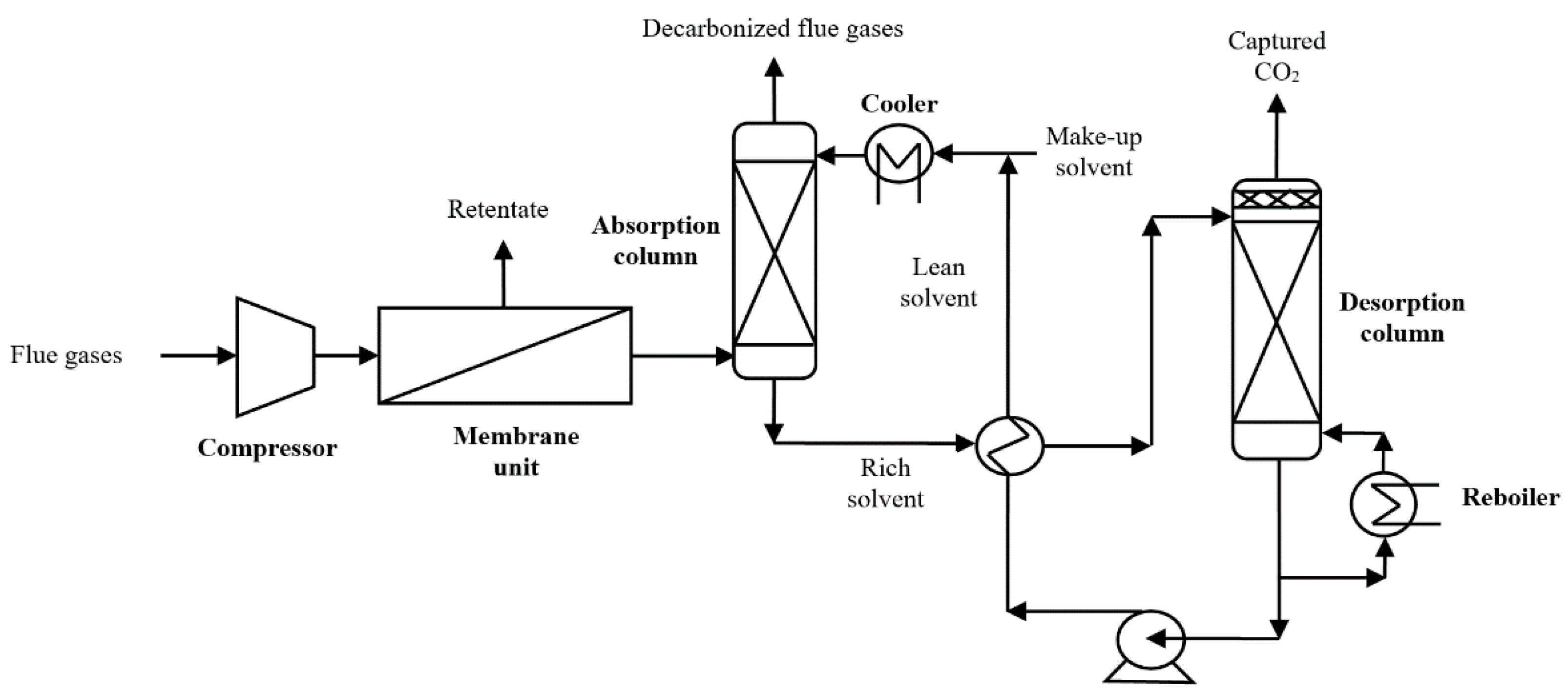
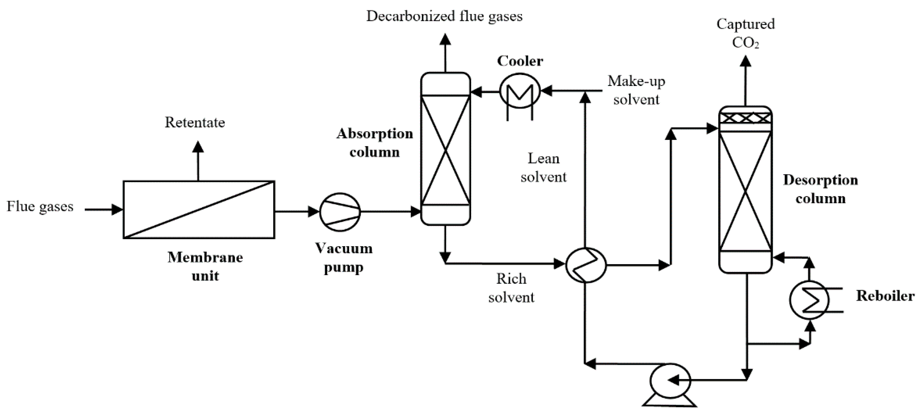
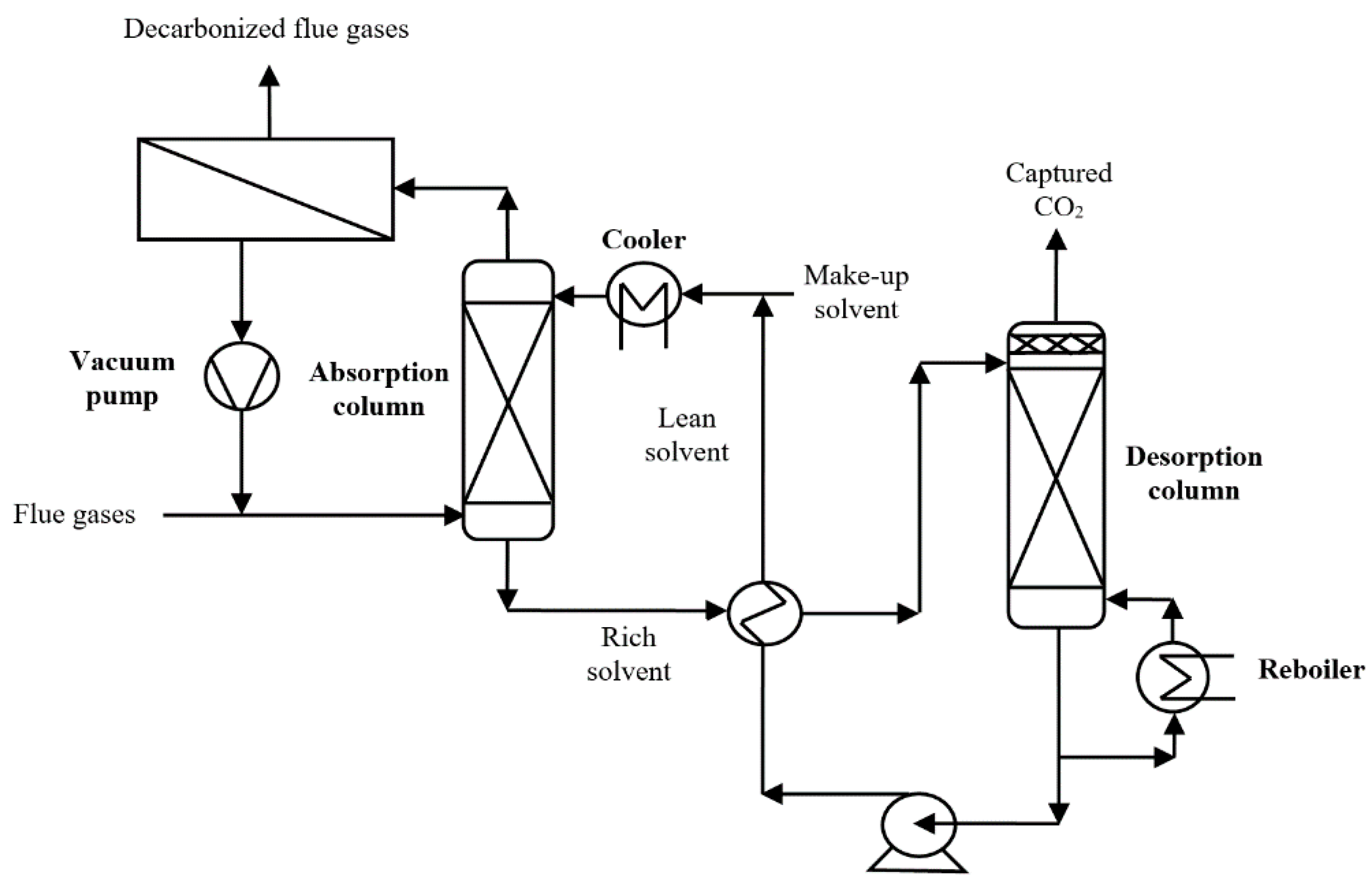
2. Hybrid Solvent-Membrane Post-Combustion CO2 Capture Configurations
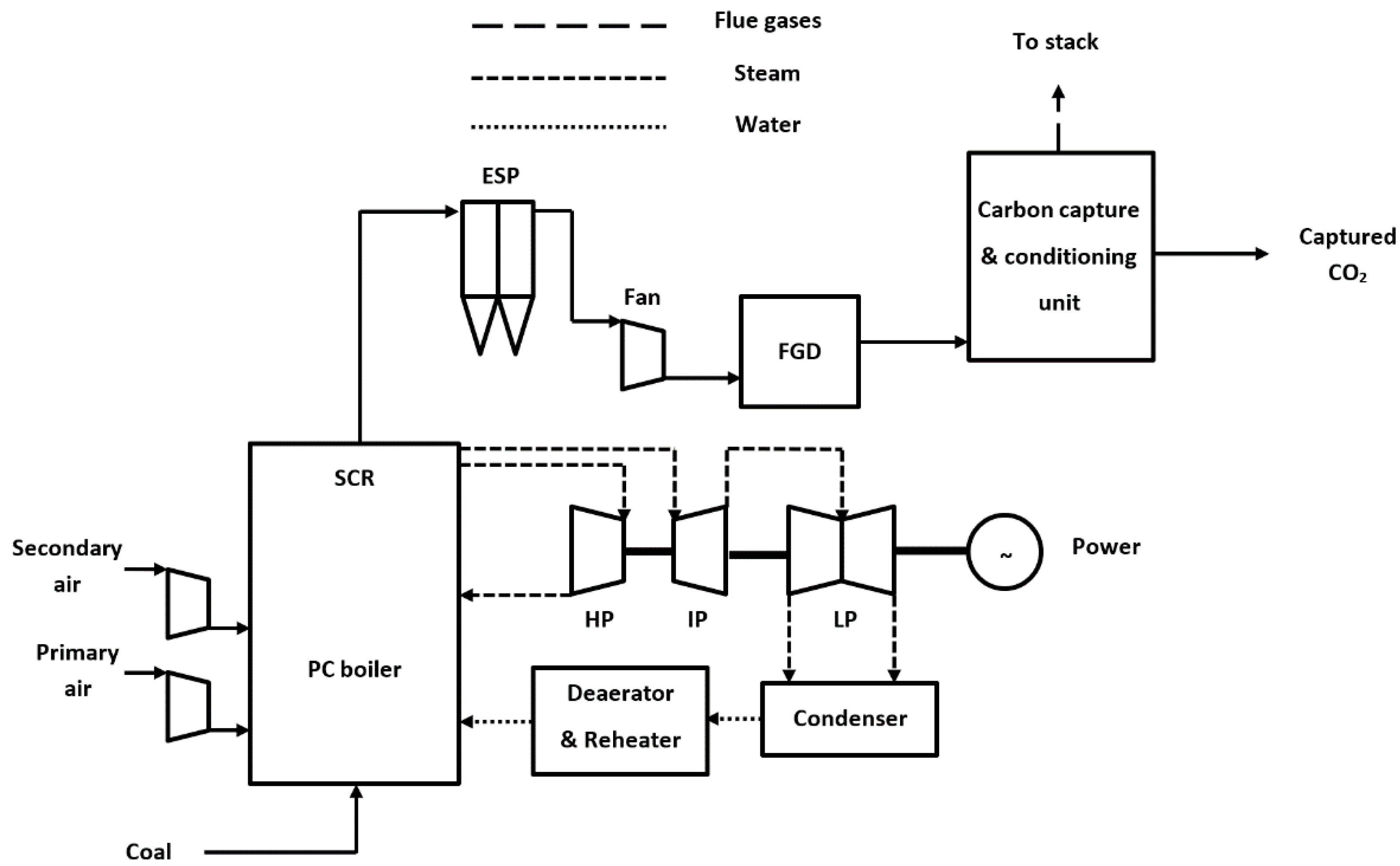
3. Decarbonized Coal-Based Super-Critical Power Plants, Main Design Characteristics and Assessment Methodology
- -
- Net and gross power plant efficiencies (ηnet/ηgross) were calculated as ratios between the net/gross power outputs (Wnet/Wgross) and coal thermal input (QFuel) as follow:
- -
- Ancillary power consumption was calculated as a sum of all electricity consumptions of various plant sub-systems:
- -
- Carbon capture rate (CCR) was calculated as a percentage of feedstock (coal) carbon to be captured:
- -
- Specific CO2 emission of the power plant (SECO2) was calculated as the ratio of emitted CO2 mass flow (FEmitted CO2) and net power output (Wnet):
- -
- Specific energy consumption for CO2 capture (SPECCA) was calculated based on net efficiencies and specific carbon emissions of both designs with and without carbon capture by the following equation [23]:
- -
- Heat duty for solvent regeneration was calculated considering the thermal energy in the reboiler divided by the mass flow of captured CO2 stream:
- -
- Ancillary power consumption for membrane separation was calculated considering the power consumption for compressor/vacuum pump of membrane unit divided by the mass flow of captured CO2 stream:
4. Results and Discussion
- Case 1.a—Super-critical power plant without carbon capture (benchmark);
- Case 1.b—Decarbonized power plant with chemical scrubbing (benchmark);
- Case 1.c—Decarbonized power plant with 3-stage membrane unit (benchmark);
- Case 2.a—Decarbonized power plant with a hybrid unit (vacuum pump);
- Case 2.b—Decarbonized power plant with a hybrid unit (compressor);
- Case 2.c—Decarbonized power plant with a hybrid unit (top absorber).
5. Conclusions
Author Contributions
Funding
Institutional Review Board Statement
Informed Consent Statement
Data Availability Statement
Conflicts of Interest
References
- Zheng, X.; Streimikiene, D.; Balezentis, T.; Mardani, A.; Cavallaro, F.; Liao, H. A review of greenhouse gas emission profiles, dynamics, and climate change mitigation efforts across the key climate change players. J. Clean. Prod. 2019, 234, 1113–1133. [Google Scholar] [CrossRef]
- Rissman, J.; Bataille, C.; Masanet, E.; Aden, N.; Morrow, W.R.; Zhou, N.; Elliott, N.; Dell, R.; Heeren, N.; Huckestein, B.; et al. Technologies and policies to decarbonize global industry: Review and assessment of mitigation drivers through 2070. Appl. Energy 2020, 266, 114848. [Google Scholar] [CrossRef]
- European Commission. The European Green Deal; COM (2019) 640 final; European Commission: Brussels, Belgium, 2019. [Google Scholar]
- Wilberforce, T.; Olabi, A.G.; Sayed, E.T.; Elsaid, K.; Abdelkareem, M.A. Progress in carbon capture technologies. Sci. Total Environ. 2021, 761, 143203. [Google Scholar] [CrossRef]
- Kohl, A.L.; Nielsen, R.B. Gas Purification, 5th ed.; Gulf Publishing Company: Houston, TX, USA, 1997. [Google Scholar]
- Bravo, J.; Drapanauskaite, D.; Sarunac, N.; Romero, C.; Jesikiewicz, T.; Baltrusaitis, J. Optimization of energy requirements for CO2 post-combustion capture process through advanced thermal integration. Fuel 2021, 283, 118940. [Google Scholar] [CrossRef]
- Luis, P.; Van Gerven, T.; Van der Bruggen, B. Recent developments in membrane-based technologies for CO2 capture. Prog. Energy Combust. Sci. 2021, 38, 419–448. [Google Scholar] [CrossRef]
- Cormos, C.C.; Dinca, C. Techno-economic and environmental implications of decarbonization process applied for Romanian fossil-based power generation sector. Energy 2021, 220, 119734. [Google Scholar] [CrossRef]
- Power, C.E.; Qiao, G.G. Polymeric CO2/N2 gas separation membranes for the capture of carbon dioxide from power plant flue gases. J. Membr. Sci. 2006, 279, 1–49. [Google Scholar] [CrossRef]
- Song, C.; Liu, Q.; Ji, N.; Deng, S.; Zhao, J.; Li, Y.; Song, Y.; Li, H. Alternative pathways for efficient CO2 capture by hybrid processes—A review. Renew. Sustain. Energy Rev. 2018, 82, 215–231. [Google Scholar] [CrossRef]
- Freeman, B.; Hao, P.; Baker, R.; Kniep, J.; Chen, E.; Ding, J.; Zhang, Y.; Rochelle, G.T. Hybrid membrane-absorption CO2 capture process. Energy Procedia 2014, 63, 605–613. [Google Scholar] [CrossRef] [Green Version]
- Dong, W.; Fang, M.; Wang, T.; Liu, F.; Yi, N. CO2 capture by using a membrane-absorption hybrid process in the natural gas combined cycle power plants. Aerosol Air Qual. Res. 2020, 21, 1–12. [Google Scholar] [CrossRef]
- Freeman, B. Bench-Scale Development of a Hybrid Membrane-Absorption CO2 Capture Process; Report DE-FE0013118; Department of Energy: Washington, DC, USA, 2020. [Google Scholar]
- Pettinau, A.; Ferrara, F.; Tola, V.; Cau, G. Techno-economic comparison between different technologies for CO2-free power generation from coal. Appl. Energy 2017, 193, 426–439. [Google Scholar] [CrossRef]
- Wu, H.; Li, Q.; Sheng, M.; Wang, Z.; Zhao, S.; Wang, J.; Mao, S.; Wang, D.; Guo, B.; Ye, N.; et al. Membrane technology for CO2 capture: From pilot-scale investigation of two-stage plant to actual system design. J. Membr. Sci. 2021, 624, 119137. [Google Scholar] [CrossRef]
- Vega, F.; Baena-Moreno, F.M.; Gallego Fernández, L.M.; Portillo, E.; Navarrete, B.; Zhang, Z. Current status of CO2 chemical absorption research applied to CCS: Towards full deployment at industrial scale. Appl. Energy 2020, 260, 114313. [Google Scholar] [CrossRef]
- U.S. Department of Energy-National Energy Technology Laboratory (NETL). Cost and Performance Baseline for Fossil Energy Plants. Volume 1a: Bituminous Coal (PC) and Natural Gas to Electricity; Report DOE/NETL-2015/1723; Department of Energy-National Energy Technology Laboratory: Pittsburgh, PA, USA, 2015.
- International Energy Agency-Greenhouse Gas R&D Programme (IEAGHG). CO2 Capture in Low Rank Coal Power Plants; Report 2006/1; International Energy Agency-Greenhouse Gas R&D Programme: Cheltenham, UK, 2006. [Google Scholar]
- Dinca, C. Critical parametric study of circulating fluidized bed combustion with CO2 chemical absorption process using different aqueous alkanolamines. J. Clean. Prod. 2016, 112, 1136–1149. [Google Scholar] [CrossRef]
- Luca, A.V.; Petrescu, L. Membrane technology applied to steel production: Investigation based on process modelling and environmental tools. J. Clean. Prod. 2021, 294, 126256. [Google Scholar] [CrossRef]
- Cormos, A.M.; Dinca, C.; Petrescu, L.; Chisalita, D.A.; Szima, S.; Cormos, C.C. Carbon capture and utilisation technologies applied to energy conversion systems and other energy-intensive industrial applications. Fuel 2018, 211, 883–890. [Google Scholar] [CrossRef]
- Chemstations, ChemCAD-Chemical Process Simulation. 2021. Available online: http://www.chemstations.net/ (accessed on 1 July 2021).
- Gazzani, M.; Romano, M.C.; Manzolini, G. CO2 capture in integrated steelworks by commercial-ready technologies and SEWGS process. Int. J. Greenh. Gas Control 2015, 41, 249–267. [Google Scholar] [CrossRef]
- Salim, W.; Li, Q.; Vakharia, V.; Chen, Y.; Wu, D.; Han, Y.; Ho, W.W. Fabrication and field testing of spiral-wound membrane modules for CO2 capture from flue gas. J. Membr. Sci. 2018, 556, 126–137. [Google Scholar] [CrossRef] [Green Version]
- Cristea, V.M.; Burca, M.I.; Ilea, F.M.; Cormos, A.M. Efficient decentralized control of the post combustion CO2 capture plant for flexible operation against influent flue gas disturbances. Energy 2020, 205, 117960. [Google Scholar] [CrossRef]
- Giordano, L.; Roizard, D.; Bounaceur, R.; Favre, E. Evaluating the effects of CO2 capture benchmarks on efficiency and costs of membrane systems for post-combustion capture: A parametric simulation study. Int. J. Greenh. Gas Control 2017, 63, 449–461. [Google Scholar] [CrossRef]
- Cormos, A.M.; Sandu, V.C.; Cormos, C.C. Assessment of main energy integration elements for decarbonized gasification plants based on thermo-chemical looping cycles. J. Clean. Prod. 2020, 259, 120834. [Google Scholar] [CrossRef]
- Liang, H.Z.; Rongwong, W.; Liu, H.; Fu, K.; Gao, H.; Cao, F.; Zhang, R.; Sema, T.; Henni, A.; Sumon, K.; et al. Recent progress and new developments in post-combustion carbon-capture technology with amine based solvents. Int. J. Greenh. Gas Control 2015, 40, 26–54. [Google Scholar] [CrossRef] [Green Version]
- Xu, J.; Wang, Z.; Qiao, Z.; Wu, H.; Dong, S.; Zhao, S.; Wang, J. Post-combustion CO2 capture with membrane process: Practical membrane performance and appropriate pressure. J. Membr. Sci. 2019, 581, 195–213. [Google Scholar] [CrossRef]
- Zhang, X.; He, X.; Gundersen, T. Post-combustion carbon capture with a gas separation membrane: Parametric study, capture cost, and exergy analysis. Energy Fuel 2013, 27, 4137–4149. [Google Scholar] [CrossRef]
- De Visser, E.; Hendriks, C.; Barrio, M.; Mølnvik, M.J.; De Koeijer, G.; Liljemark, S.; Le Gallo, Y. Dynamis CO2 quality recommendations. Int. J. Greenh. Gas Control 2008, 2, 478–484. [Google Scholar] [CrossRef]


| Plant Sub-System | Value |
|---|---|
| Coal composition (% wt. dry) and lower heating value (LHV) | 72.31% C, 4.10% H, 1.70% N, 7.46% O, 0.57% S, 13.90% ash; Moisture: 8.00%; Calorific value: 25.17 MJ/kg |
| Steam cycle [18] | |
| Live/reheated temperature | 585 °C/580 °C/580 °C |
| Live/reheated pressure | 290 bar/80 bar/25 bar |
| BFW temperature | 220 °C |
| BFW pressure | 312 bar |
| Turbine efficiency | 90% (HP)/92% (MP)/95% (LP) |
| Condensing pressure | 46 mbar |
| Cooling water inlet temperature | 15 °C |
| Minimum approach temperature ΔTmin. | 10 °C |
| Pump efficiency | 85% |
| CO2 capture unit by chemical scrubbing [19] | |
| Solvent used | MDEA solution (50% wt.) |
| Decarbonization rate | 90% |
| Absorber | 20 trays |
| Desorber | 15 trays |
| Desorber bottom maximum temperature | 125 °C |
| Solvent regeneration thermal duty | 3 GJ/t CO2 |
| Solvent losses | 1 kg/t CO2 |
| Steam pressure for solvent regeneration | 4 bar |
| Steam temperature for solvent regeneration | 144 °C |
| CO2 capture unit by membrane [20] | |
| Membrane type | Spiral wound-Cross flow |
| Carbon capture rate | 90% |
| Permeance data | CO2: 370 GPU |
| O2: 7.41 GPU | |
| N2: 1.85 GPU | |
| Operating temperature | 45–55 °C |
| Pressure ratio | 5–10 |
| Compressor/vacuum pump efficiency | 85% |
| CO2 conditioning unit [21] | |
| Drying unit | Tri-Ethylene-Glycol (TEG) system |
| Compression unit | Four-stage compression |
| Efficiency of compressor | 85% |
| Final compressing pressure | 120 bar |
| CO2 quality specification (vol. %) | min. 95% CO2, max. 1500 ppm CO, max. 300 ppm H2O, max. 50 ppm H2S, max. 4% other non-condensable gases (N2, Ar, etc.) |
| Power plant auxiliaries | |
| Power consumption for fuel handling | 0.5% of thermal input |
| Efficiency of denitrification unit | 98% NOx removal efficiency |
| Efficiency of desulfurization unit | 98–99% SOx removal efficiency |
| Efficiency of pumps, fans | 85% |
| Heat exchanger pressure drops | 2–4% of inlet pressure |
| Main Plant Data | Units | Case 1.a | Case 1.b | Case 1.c |
|---|---|---|---|---|
| Coal input | t/h | 330.07 | 420.14 | 459.00 |
| Coal calorific value | MJ/kg | 25.17 | ||
| Coal thermal energy (A) | MW | 2307.78 | 2937.51 | 3209.17 |
| Steam turbine output | MW | 1057.82 | 1138.73 | 1473.69 |
| Gross electric power output (B) | MW | 1057.82 | 1139.82 | 1473.69 |
| Coal processing | MW | 11.53 | 14.68 | 16.07 |
| Carbon capture & compression | MW | - | 64.97 | 393.10 |
| Power island consumption | MW | 46.32 | 60.17 | 64.52 |
| Ancillary electricity consumption (C) | MW | 57.82 | 139.82 | 473.69 |
| Net power output (D = B − C) | MW | 1000.00 | 1000.00 | 1000.00 |
| Gross efficiency (B/A × 100) | % | 45.83 | 38.76 | 45.92 |
| Net efficiency (D/A × 100) | % | 43.33 | 34.04 | 31.16 |
| Plant decarbonization yield | % | 0.00 | 90.00 | 90.00 |
| CO2 specific emission | kg/MWh | 800.27 | 101.80 | 110.95 |
| SPECCA | MJ/kg | - | 3.24 | 4.71 |
| Heat duty solvent regeneration | GJ/t | - | 2.99 | - |
| Power consumption membrane | kWh/t | - | - | 273.59 |
| Main Plant Data | Units | Case 2.a | Case 2.b | Case 2.c |
|---|---|---|---|---|
| Coal input | t/h | 471.79 | 472.83 | 433.97 |
| Coal calorific value | MJ/kg | 25.17 | ||
| Coal thermal energy (A) | MW | 3298.59 | 3305.87 | 3034.16 |
| Steam turbine output | MW | 1322.65 | 1317.59 | 1201.14 |
| Gross electric power output (B) | MW | 1322.65 | 1317.59 | 1201.14 |
| Coal processing | MW | 16.49 | 16.62 | 15.17 |
| Carbon capture & compression | MW | 239.56 | 234.33 | 123.27 |
| Power island consumption | MW | 66.60 | 66.64 | 62.70 |
| Ancillary electricity consumption (C) | MW | 322.65 | 317.59 | 201.14 |
| Net power output (D = B − C) | MW | 1000.00 | 1000.00 | 1000.00 |
| Gross efficiency (B/A × 100) | % | 40.09 | 39.85 | 39.58 |
| Net efficiency (D/A × 100) | % | 30.31 | 30.25 | 32.95 |
| Plant decarbonization yield | % | 90.00 | 90.00 | 90.00 |
| CO2 specific emission | kg/MWh | 114.55 | 114.58 | 105.38 |
| SPECCA | MJ/kg | 5.20 | 5.24 | 3.76 |
| Heat duty solvent regeneration | GJ/t | 2.41 | 2.52 | 2.64 |
| Power consumption membrane | kWh/t | 168.93 | 163.28 | 64.27 |
| Component | Case 1.b | Case 1.c | Case 2.a | Case 2.b | Case 2.c |
|---|---|---|---|---|---|
| Carbon dioxide | 99.95 | 96.34 | 99.96 | 99.96 | 99.96 |
| Nitrogen | 0.02 | 0.89 | 0.01 | 0.01 | 0.02 |
| Oxygen | 30 ppm | 2.75 | 38 ppm | 35 ppm | 34 ppm |
| Water | 172 ppm | 200 ppm | 190 ppm | 192 ppm | 168 ppm |
| Other species | <0.01 | <0.01 | <0.01 | <0.01 | <0.01 |
Publisher’s Note: MDPI stays neutral with regard to jurisdictional claims in published maps and institutional affiliations. |
© 2021 by the authors. Licensee MDPI, Basel, Switzerland. This article is an open access article distributed under the terms and conditions of the Creative Commons Attribution (CC BY) license (https://creativecommons.org/licenses/by/4.0/).
Share and Cite
Cormos, C.-C.; Petrescu, L.; Cormos, A.-M.; Dinca, C. Assessment of Hybrid Solvent—Membrane Configurations for Post-Combustion CO2 Capture for Super-Critical Power Plants. Energies 2021, 14, 5017. https://doi.org/10.3390/en14165017
Cormos C-C, Petrescu L, Cormos A-M, Dinca C. Assessment of Hybrid Solvent—Membrane Configurations for Post-Combustion CO2 Capture for Super-Critical Power Plants. Energies. 2021; 14(16):5017. https://doi.org/10.3390/en14165017
Chicago/Turabian StyleCormos, Calin-Cristian, Letitia Petrescu, Ana-Maria Cormos, and Cristian Dinca. 2021. "Assessment of Hybrid Solvent—Membrane Configurations for Post-Combustion CO2 Capture for Super-Critical Power Plants" Energies 14, no. 16: 5017. https://doi.org/10.3390/en14165017
APA StyleCormos, C.-C., Petrescu, L., Cormos, A.-M., & Dinca, C. (2021). Assessment of Hybrid Solvent—Membrane Configurations for Post-Combustion CO2 Capture for Super-Critical Power Plants. Energies, 14(16), 5017. https://doi.org/10.3390/en14165017