1. Introduction
Servovalves are electro-hydraulic, continuously acting valves that transform a changing analog or digital input signal into a stepless hydraulic output (flow rate) [
1]. The term servovalve describes a valve design with bushing spool assembly, characterized by high precision metering edges [
1]. Their invention in the late 1930s was a breakthrough for many industries, as they proved to be high-performance modulating valves due to their excellent high frequency response and short step response time [
1]. By virtue of their reliability and low weight, servovalves are widely used in aerospace for primary and secondary flight controls and for fuel control [
2,
3]. A servovalve is also used in many industrial control systems where high-performance levels are needed [
3].
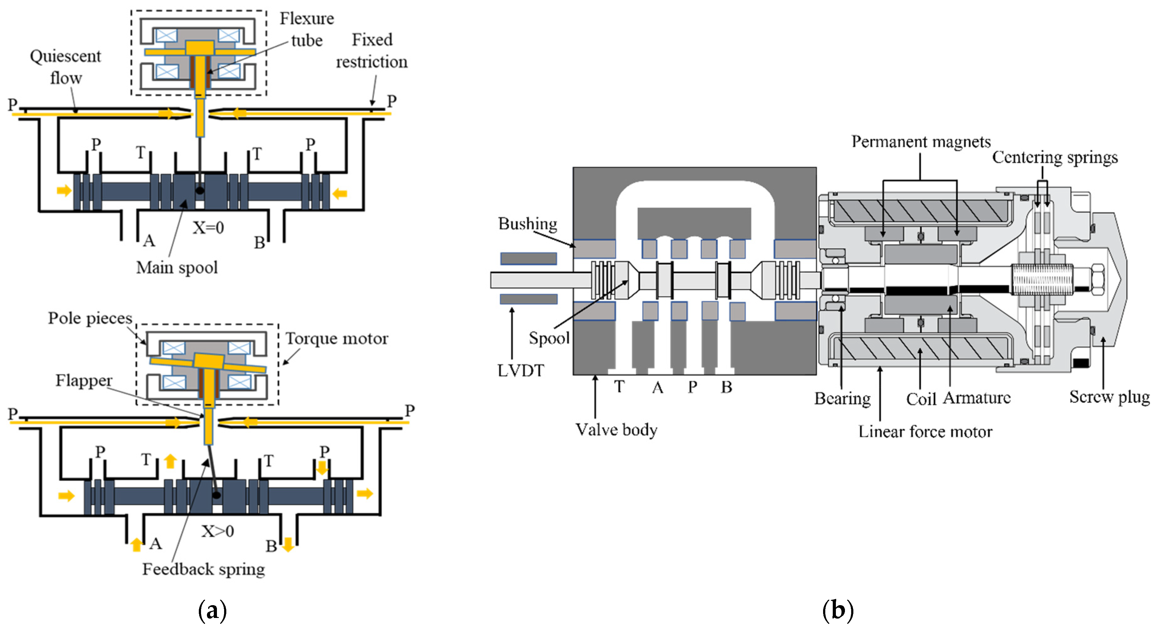
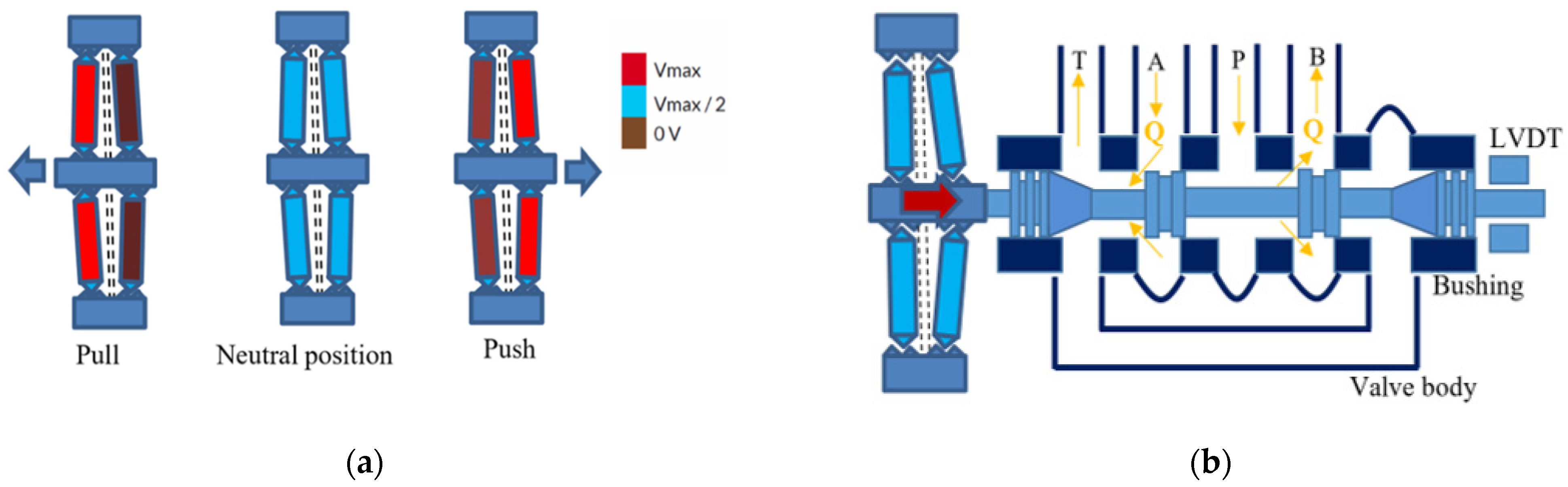
There are mainly two types of commercially available servovalves: the two-stage type (
Figure 1a), in which a modulating flow piston, called a spool, is controlled by a pilot stage, and the direct drive type (
Figure 1b), in which a linear force motor directly moves the spool [
3,
4,
5,
6]. Concerning the former, there are three main types depending on the architecture of the pilot stage: the double-nozzle-flapper, the deflector jet, and the jet pipe.
Figure 1a shows the architecture of a four-way three-position (4/3) double nozzle-flapper servovalve. The pilot stage is equipped with a torque motor consisting of permanent magnets, pole pieces, and an armature. A flexure tube is used to support the flapper while separating the torque motor from the hydraulic fluid. A feedback spring connects the main spool with the flapper to achieve mechanical feedback (electrical feedback in two-stage servovalves is also possible using a position transducer). When the coil is energized, a proportional torque is generated on the flapper, which is deflected according to the direction and intensity of the applied current (usually less than 0.05 A [
2]). The deflection of the flapper partially restricts the pilot oil flowing out of one of the nozzles, creating a pressure difference on the lateral faces of the spool, which is forced to move, bending the feedback spring. The spool stops in a final position determined by the equilibrium of the forces acting on the spool (actuation force = flow force + feedback spring force) [
1,
2,
3,
4,
5]. The electrical input power has an order of magnitude of 0.1 W, which is amplified to at least 10 W of hydraulic power in the first stage and is then converted by the main spool to control around 10 kW of hydraulic output power. Therefore, the valve power amplification factor is 10
5 [
2].
Direct drive servovalves are also manufactured despite being used less than two-stage configurations are. Linear force motors (LFMs) are used to directly move the spool, providing better performance than solenoids. Compared to a two-stage design, a direct drive architecture has the advantage of being simpler to construct but has the disadvantage of having worse performance in terms of response speed and chip shear force capability [
6].
The main difference between a servovalve (both two-stage and single-stage) and a proportional valve is that the former employs a bushing sleeve, which allows finer tolerances to be achieved and hence lower overlaps between spool lands and slots [
3,
7].
Although the architectures of these vales have not substantially changed for many years, there are a few drawbacks that are still unsolved. Concerning two-stage servovalves, there is sensitivity to contamination in the pilot stage, which can cause premature wear and failure, and a significant quiescent flow in the pilot stage, which consumes a significant part of the input power since oil continuously flows through the pilot stage even when the spool is in the neutral position [
1,
2,
3,
4]. Another issue concerned with two-stage servovalves is the complexity of the torque motor, which is made up of many sensitive mechanical and electrical parts, such as the flexure tube, being manufactured very accurately in order to achieve the required stiffness. The pilot stages of two-stage servovalves are also subject to intense cavitation, as shown by very interesting research studies [
8,
9,
10,
11], which also highlight that commercially available pilot stages are not optimized geometries [
8,
9,
10,
11,
12].
Concerning single stage servovalves, the main issues are the high weight and large dimensions caused by the large linear force motors employed to directly move the spool.
A way to solve these problems could be to use piezoelectric actuators, which can provide high frequency response and high actuation forces [
13]. A piezo valve, a valve actuated by a piezoelectric actuator, can give the advantage of removing both the torque motor and the flexure tube from a two-stage servovalve design, thus reducing complexity and manufacturing costs. Furthermore, by using piezoelectric actuators for the direct actuation of single-stage servovalves, advantages such as faster dynamic response and lower weight can be obtained compared to linear force motors.
Some piezo valves developed in the scientific literature were described in [
3] and in [
14]. In this paper, the analysis is deepened by discussing more designs and new architectures of electro-hydraulic servovalves that exploit actuation systems based on piezo actuators. Their operating principles will be introduced, and their performance parameters will be discussed in detail.
2. Piezoelectric Actuators
Piezoelectric actuators (PEAs) use the piezoelectric inverse effect to convert electrical energy into mechanical energy. The most used material for these actuators is lead zirconate titanate. As explained in the introduction, the use of PEAs instead of electromagnetic actuators in servovalves could help to solve the typical problems associated with these valves. In addition, the piezoelectric actuation could be capable of extending the bandwidth of current servovalves (up to 150–300 Hz) into a kiloHertz range [
15]. It has also been proven that PEAs can be employed for several working cycles without being damaged [
16]. PEAs are susceptible to temperature variation, have a low Curie temperature, and their actuation force decreases with temperature [
17]. However, these weaknesses should not be an issue for the typical operating range of the hydraulic oil used in servovalves (30–60 °C). The main problems of PEAs to be managed in servovalves are hysteresis (which can be as high as 20%) and creep, which could affect the accuracy of control [
18]. Therefore, closed-loop control is mandatory to tackle this problem, and techniques to deal with these problems have been shown in the literature [
19,
20,
21].
Commercially available piezo actuators are produced by a few manufacturers such as Thorlabs [
22], Noliac [
23], Piezodirect [
24], Piceramic [
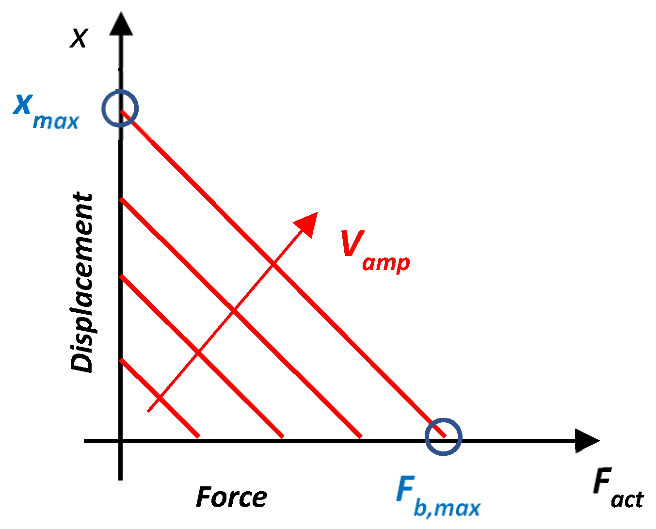
25], etc. In order to produce displacement, an amplified voltage (
), usually up to 100 or 200 V, must be applied to a PEA. The PEA in turn exerts an actuation force linearly decreasing with its displacement.
Figure 2 qualitatively shows the relationship between the actuation force
and the displacement (
). For a given voltage applied to the PEA, the relation is a straight line with a certain slope, which translates along the horizontal axis when the voltage is changed.
Therefore, the maximum actuation force, called the blocking force (
, is obtained when an actuator is blocked from moving. When the maximum voltage is applied, the maximum blocking force is obtained (
. The blocking force can be put in relation to the voltage using a force/voltage coefficient (
), thus obtaining:
where
is the actuator stiffness. The maximum displacement (
), called the free stroke, is obtained for a null actuation force, namely, when a free actuator experiences no resistance to movement, and when the maximum voltage is applied.
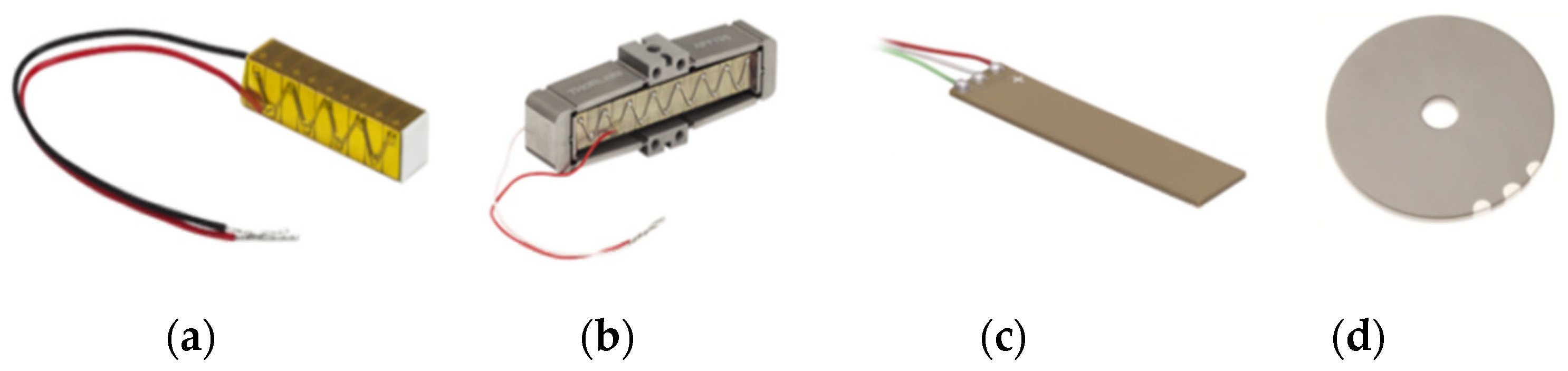
The main types of commercially available PEAs include piezo stacks (
Figure 3a), amplified piezo stacks (
Figure 3b), bimorph (rectangular) benders (
Figure 3c), and ring benders (
Figure 3d).
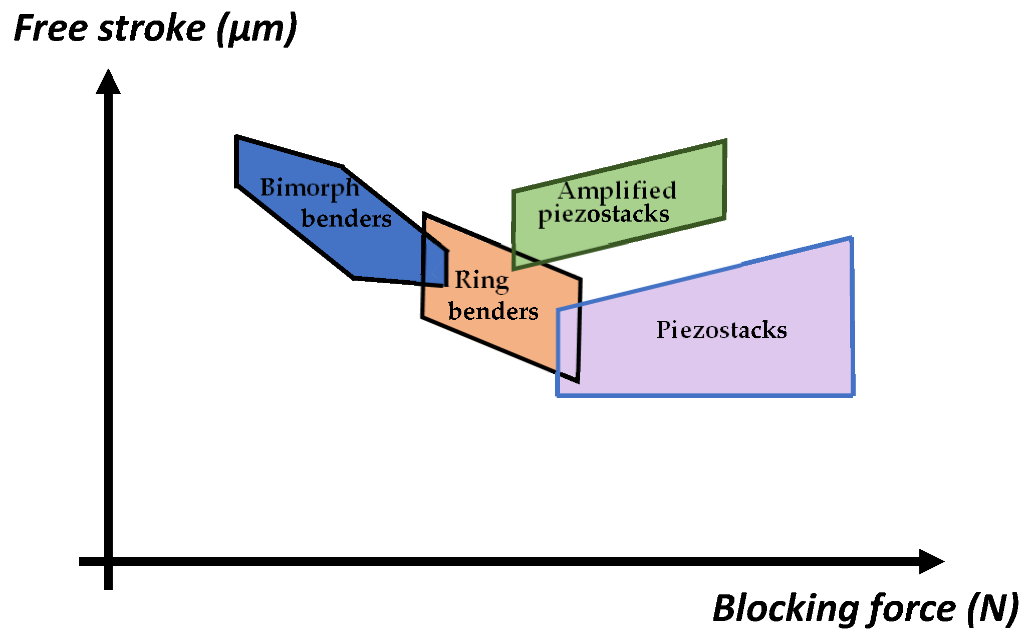
Piezo stacks are very large and can generate very high actuation forces but low displacement; amplified piezo stacks use amplification systems to reach higher displacement but at the expense of the actuation force, which is lower than that of piezo stacks. Bimorph (rectangular) benders and ring benders are much smaller than piezo stacks and amplified piezo stacks but generate lower actuation forces. A ring bender generates a higher actuation force than a rectangular bender, but the latter achieves higher displacement. A comparison among these actuators is provided in
Table 1 and in
Figure 4. As shown in
Table 1, the different actuator designs have different characteristics. Blocking force and free displacement are plotted in
Figure 4 for these actuators [
23].
3. Servovalves Driven by Piezo Stack Actuators
A piezo stack actuator, shown in
Figure 3a, consists of a series of piezoelectric elements stacked one on top of the other and are enclosed between two electrodes. The thickness of the layers is to the order of 25–100 µm. The voltage to be applied depends on the material and the thickness of each element. The longer the stack, the higher the displacement achieved by the stack. As an example, a commercially available piezo stack actuator, model NAC2023 produced by Noliac, is 15 cm long and can produce a blocking force of 9450 N with a free stroke of 244.2 μm [
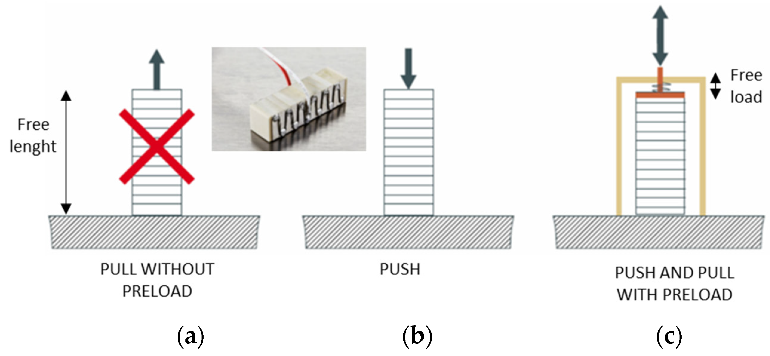
23]. Without preload, piezo stacks are sensitive to pulling forces; therefore, it is recommended to apply a pre-load in order to optimize the performance of the actuators [
23].
It has been proven that selecting a correct value for the preload allows a longer lifetime to be achieved for this type of PEA. The values for the optimum preload ranges from 20 to 50 percent of the maximum blocking force [
26]. The force must be applied to the full surface of the actuator in order to ensure good load distribution.
Figure 5 shows the wrong and correct operation of a piezo stack.
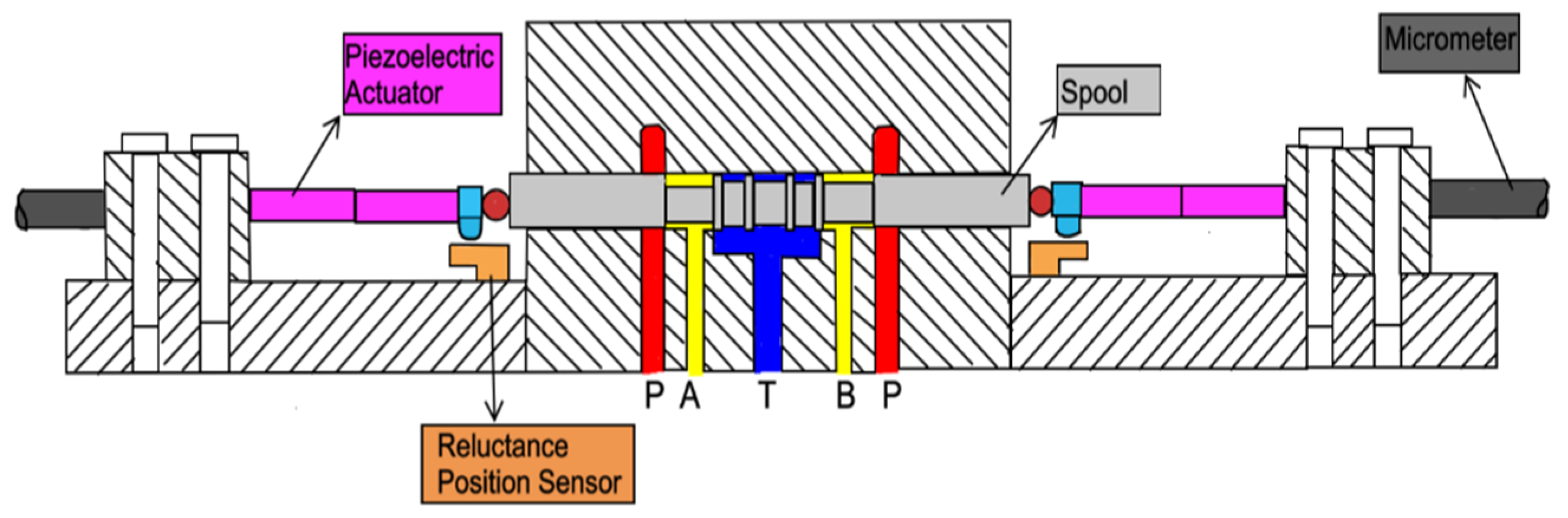
Back in the 1990s, a research study was conducted on the application of piezo stacks to servovalves [
27]. There were two piezo stack actuators that were connected to both sides of a spool through steel balls to directly actuate the spool of the servovalve, as shown in
Figure 6. The piezoelectric multilayer actuators were pre-compressed by about 20 µm. The displacement of the spool was measured by a non-contact reluctance-type position sensor. Feed forward control was employed in order to obtain high speed response. The authors stated that this servovalve had a bandwidth of over 5 kHz and could pass a flow of 5.4 L/min for a pressure drop of 100 bar. The application of this valve architecture to higher flow rate values is not documented in the paper. This research study can be regarded as the pre-cursor for more recent studies.
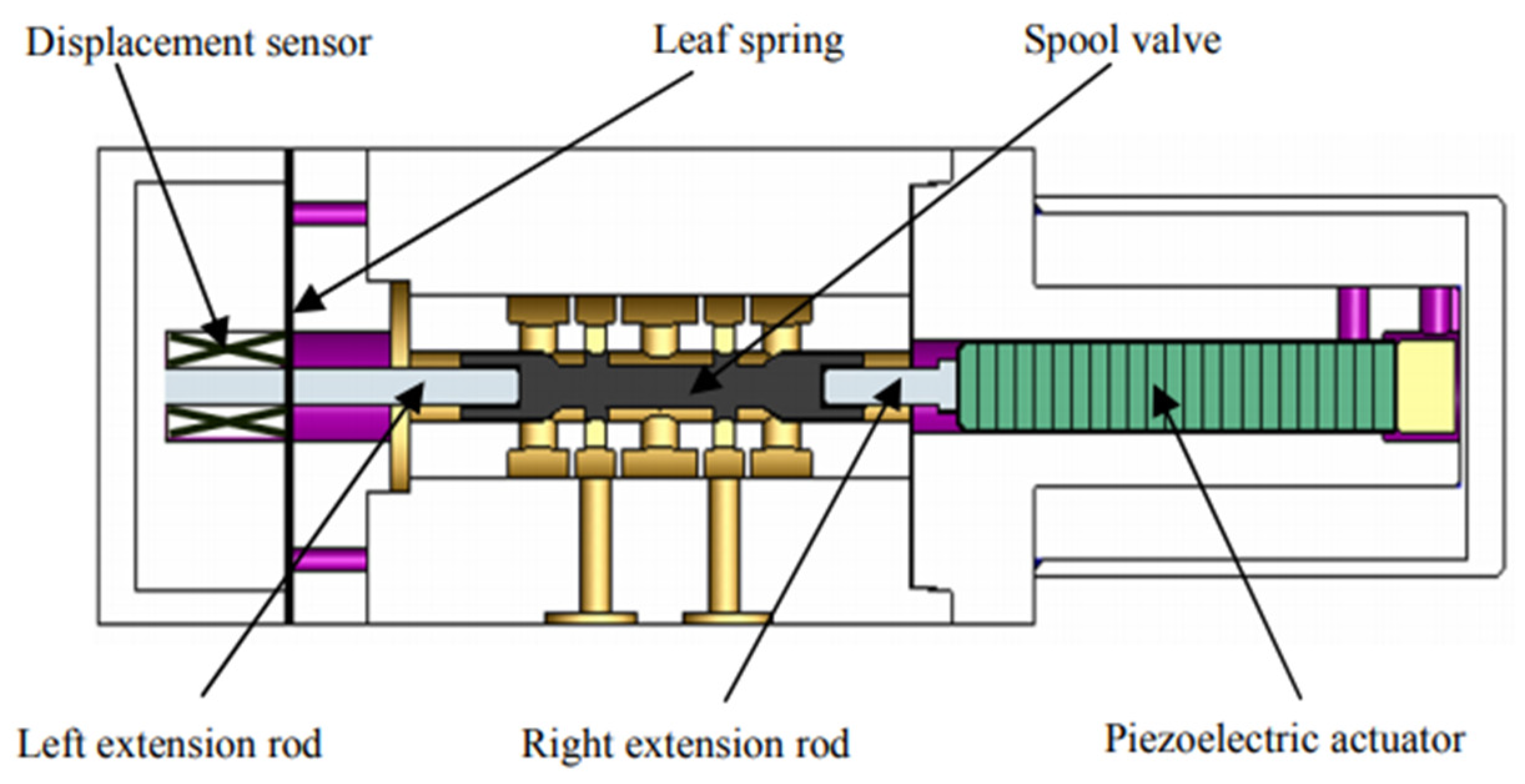
The main problems of that architecture are the high cost of using two piezo stack actuators. To cope with this problem, in [
28], a spring mechanism and only one piezo stack were used to obtain bidirectional spool control, as shown in
Figure 7. A leaf spring allowed the spool to be kept in the neutral position when no voltage was applied to the piezo stack. Nonlinear effects such as hysteresis and creep were managed using a Fuzzy Logic control algorithm with a Preisach hysteresis nonlinear model in a feedforward loop. The valve was tested at a very low flow rate (up to 4 L/min for a supply pressure of 7 MPa). In these conditions, the results illustrated that the piezo valve had a frequency response bandwidth of 470 Hz, and the system could reach the steady state in 4.77 ms.
Again, the application of this valve architecture to higher values of flow rate and pressure was not addressed in the paper.
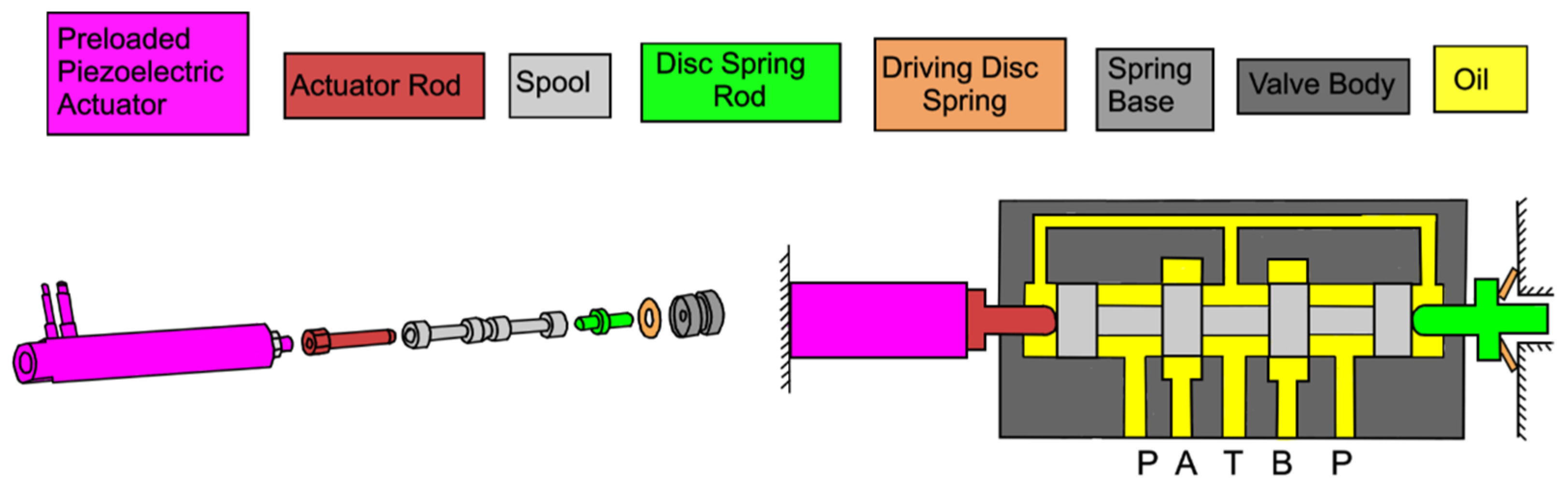
In [
29], a similar servovalve was developed but using four components: a piezoelectric stack coupled with a rod, a spool, a disc spring rod, and a driving disc spring, as shown in
Figure 8. The four components were not fixed together but were in contact with each other to drive the spool. An internal preload was applied to the piezo stack to cope with the pulling forces generated by the inertia and the friction of the spool. With a supply pressure of 21 MPa, the flow rate was measured to be 4.45 L/min at a maximum input voltage of 5 V. The −3 dB frequency was 710 Hz, and the step response time of the spool displacement was 0.52 ms.
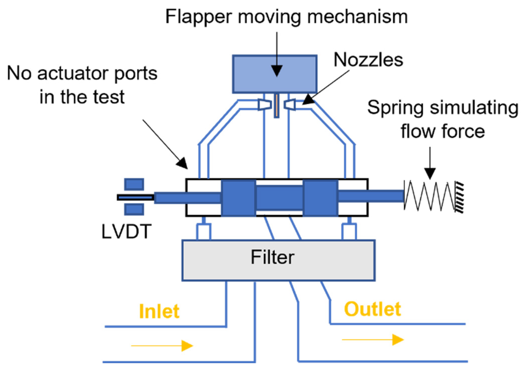
In [
30,
31], piezo stack actuators were used in place of the torque motor for the actuation of the flapper in a double nozzle-flapper servovalve. There were two flapper moving mechanisms that were proposed to compensate for the hysteresis and the thermal expansion of the piezo stacks, and these systems were experimentally assessed. A simplified valve was used in the experimental test; there were no actuator ports, and a spring was used to simulate the flow force, as shown in
Figure 9. The experimental results showed that with a supply pressure of 210 bar, a high dynamic response could be obtained: concerning the first moving mechanism, the phase lag was −90 deg for a frequency of 200 Hz, and the amplitude ratio was −3 db for a frequency of 150 Hz. The results were further improved by using the second mechanism, the phase shift being −90 deg for a frequency of 300 Hz.
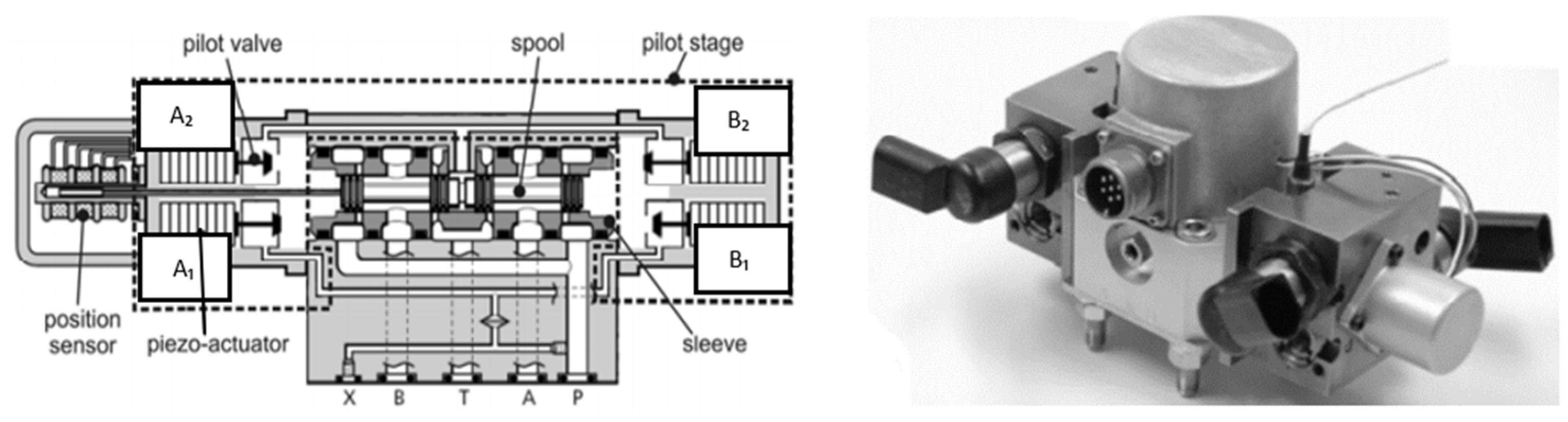
In [
32], four two-way two position (2/2) poppet valves, each driven by a piezo stack actuator, were used as flow variable resistors in place of the torque motor to actuate the main stage of a conventional two-stage servovalve, as shown in
Figure 10. Each piezo actuator had a nominal full stroke of 40 µm and a driving force of 2000 N at an operating voltage of 160 V. A linear variable differential transformer (LVDT) was used to measure the main spool position and to achieve closed-loop control.
The operation principle of this valve configuration can be described in the following way: while valves A2 and B1 are closed, valves B2 and A1 are open, and vice-versa. By changing the stroke of each pilot valve and the phase lag between them, flow modulation can be achieved. The valve was capable of controlling 32 L/min at a pressure drop of 70 bar. This architecture provided better dynamics than a conventional servovalve. Indeed, tests performed at 210 bar showed that the rise time was only 1.07 ms to reach an opening of 0.52 mm. The frequency values corresponding to an amplitude decrease of −3 dB and a phase lag of −90 deg were 340 Hz and 300 Hz, respectively, with reference to the maximum opening.
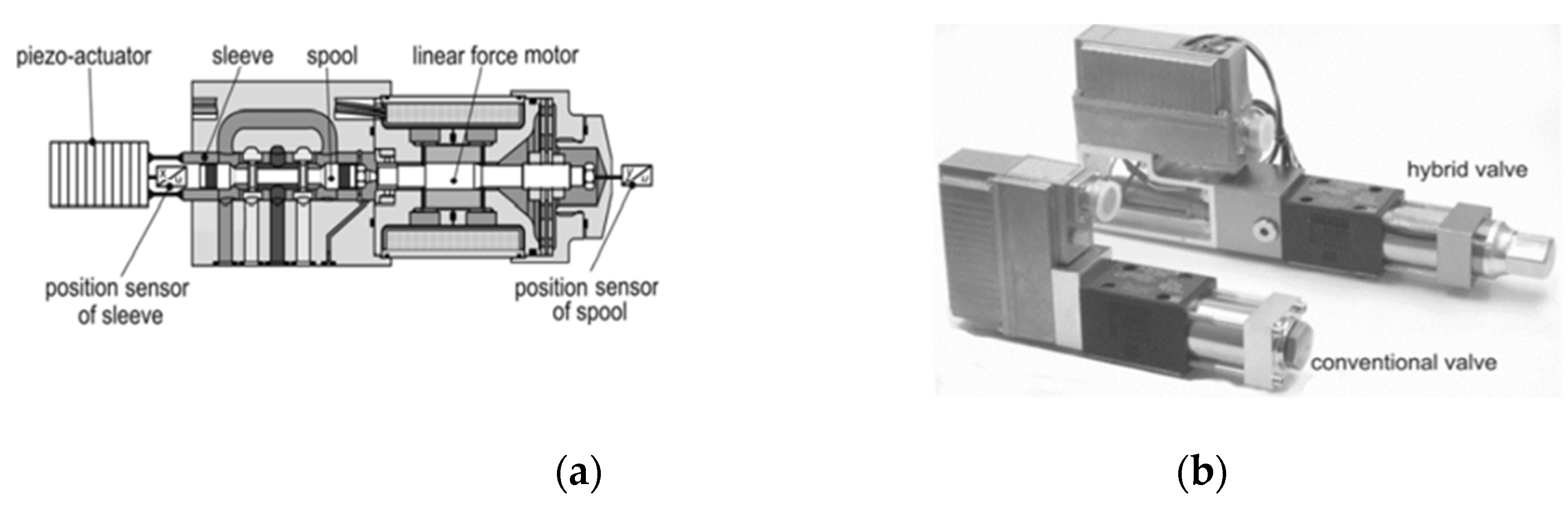
In [
32], a new design for a direct drive servovalve was also proposed, called a hybrid valve, in which the bushing sleeve was actuated by a piezo stack with a stroke of ±50 µm, and the spool was driven by a linear force motor with a stroke of ±0.5 mm, as shown in
Figure 11. A closed-loop control system was used to simultaneously control the position of the spool and the position of the sleeve while compensating for hysteresis. The experimental results, performed with a pressure drop of 35 bar across each metering chamber, showed that the hybrid valve had a nominal flow rate of 40.5 L/min. The frequency values corresponding to an amplitude decrease of −3 dB and a phase lag of −90 deg were 620 Hz and 850 Hz, respectively. Due to the additional leakage between the moving sleeve and the valve housing, the overall internal leakage of the hybrid valve was about 1 L/min, thus being greater than that of commercially available direct drive valves.
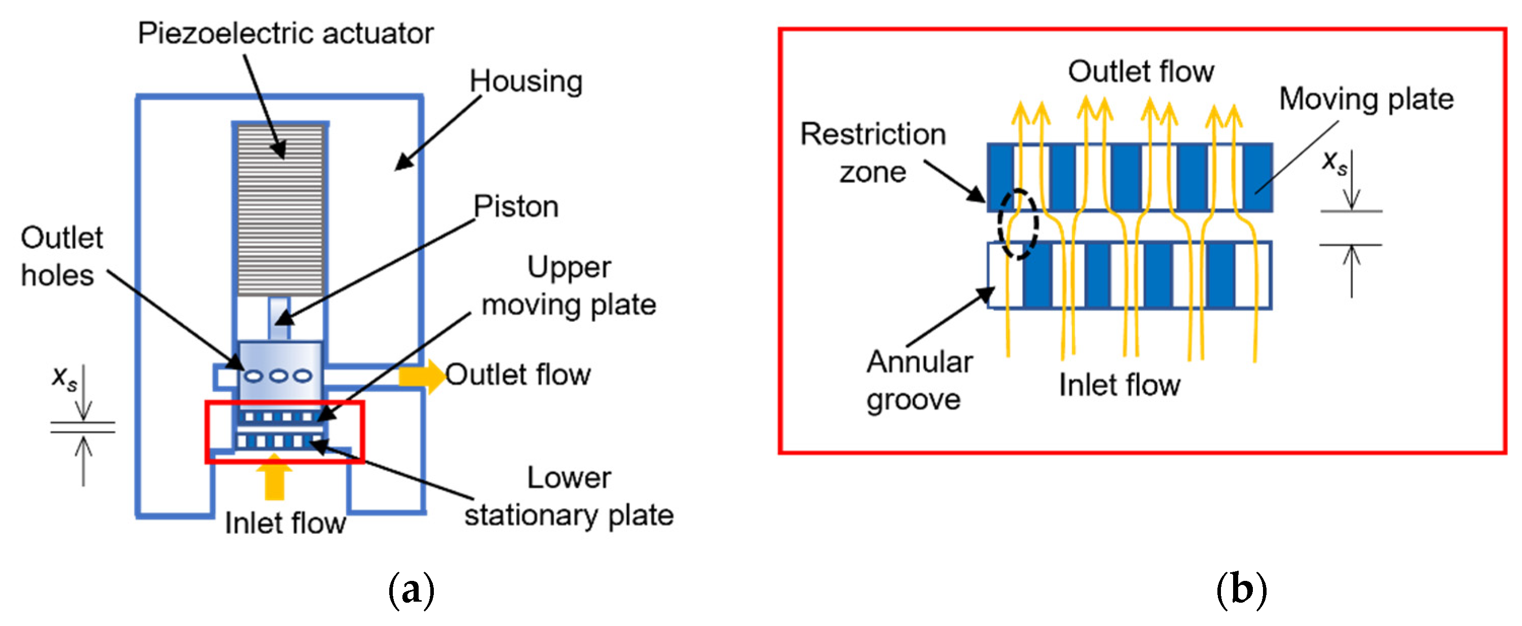
In [
15], a piezo stack actuator was used to move an upper moving plate coupled with a stationary plate, as shown in
Figure 12. Annular grooves were built in the two opposing plates to form multiple metering edges (
Figure 12b). The working principle was to control the flow rate by adjusting the axial distance between the two plates,
xs. This piezo valve provided several advantages, such as the reduction of internal leakage, very good valve response, an increase in the flow area, and high flow rates for a given pressure drop.
The piezo valve prototype used a piezoelectric actuator which had a free stroke of 68 µm and could produce a blocking force of up to 12 kN. The valve was capable of opening or closing fully in less than 1.5 ms and could pass a flow of 65 L/min at a pressure drop of 20 bar. The bandwidth performance of the valve was also investigated experimentally: it was up to 425 Hz for input voltage amplitudes up to 85 per cent of the maximum [
15].
4. Servovalves Driven by Amplified Piezo Stack Actuators
The main weakness concerning the use of a piezo stack actuator is its low stroke, which is very small compared to its length. Indeed, these PEAs generate values of displacement that are usually less than 100 µm. Therefore, the main issue associated with piezo stacks is the large dimensions of the valve; in the case of direct actuation, the low stroke of the spool causes low flow rate through the valve. In addition, asymmetrical piezo stack designs, e.g., [
15,
28,
29], will suffer from the offset and hence reduced amplitude because of thermal expansion as they heat up (stack heating is significant when operating at high voltage and high frequency due to the high peak current that is generated).
To increase the displacement (hence, the flow rate) and to reduce thermal problems, amplification systems can be adopted.
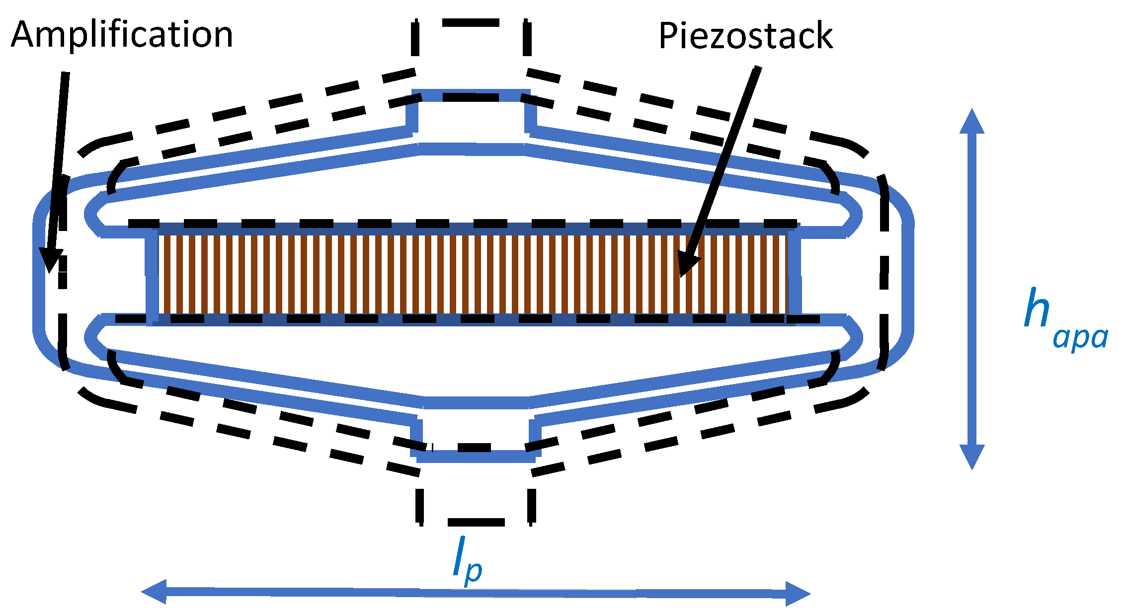
Figure 13 shows an example of an amplified piezo stack actuator (APA) based on an elliptical shell used to transform the deformation occurring along the main axis (
into deformation along the short axis (
, which is amplified [
33]. This amplification mechanism allows the PEA to achieve large deformation (up to 1000 µm) but at the expense of the actuation force, which is much lower than a piezo stack [
34]. This amplified piezo stack design can give a significant advantage over other piezo stack designs in terms of temperature independence since the thermal expansion coefficient of the shell is designed to match the stack, so there will be no thermal effect.
In [
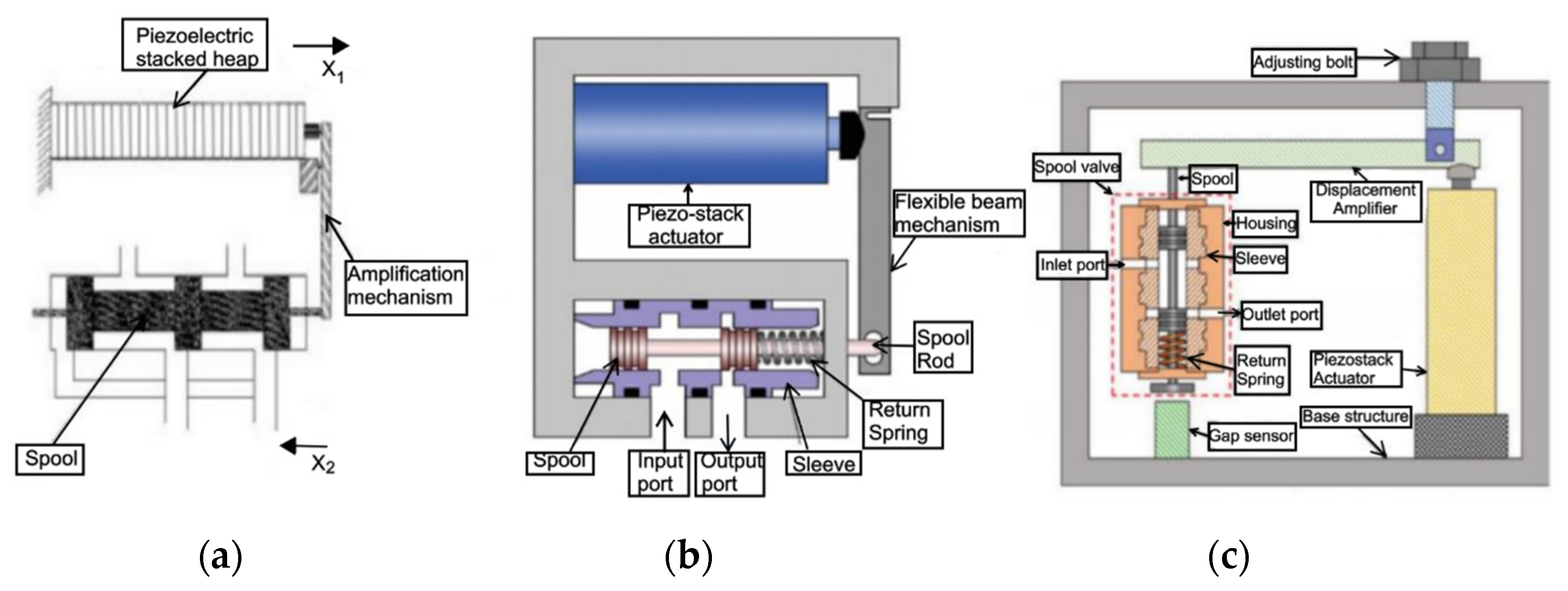
35], an amplified piezo stack actuator was adopted to directly actuate the spool, as shown in
Figure 14. A prototype was constructed. The amplification system was a lever mechanism connecting the spool to a preloaded piezo stack. The lever was able to amplify the displacement of the piezo stack from 0.06 mm to 0.3 mm. The maximum voltage applied to the piezoelectric actuator was 800 V. The valve was constructed to obtain 7.5 L/min for an inlet pressure of about 100 bar. A very lightly damped mode at about 340 Hz was noticed.
Similar valve architectures were developed in [
36,
37,
38], in which a piezo stack actuator with a lever amplification mechanism was used to directly actuate the main stage valve, as shown in
Figure 15. To control the position of the spool, closed-loop control was used.
The direct drive piezo valve developed in [
36] was a pneumatic valve, which proved to be much faster than a normal solenoid valve. The architecture proposed in [
37] was very similar but used with oil. With the maximum input voltage, the spool displacement reached 0.56 mm, and the maximum flow rate was 22.8 L/min for a pressure drop of 30 bar. The −3 dB frequency was 181 Hz.
A similar piezo valve, developed in [
38], was tested at various operating temperatures by the use of a heat chamber. It was shown that good control was achieved even at very high temperatures. The experimental results showed that at 30 °C, the input voltage necessary to reach a maximum spool position of 0.3 mm was 80 V, and the valve was capable of passing 9 L/min (the pressure drop through the valve was not reported in the paper).
The problem associated with these designs is that the lever mechanism does not provide temperature compensation; therefore, changes in performance can be expected because of thermal expansion when the stack heats up during operation.
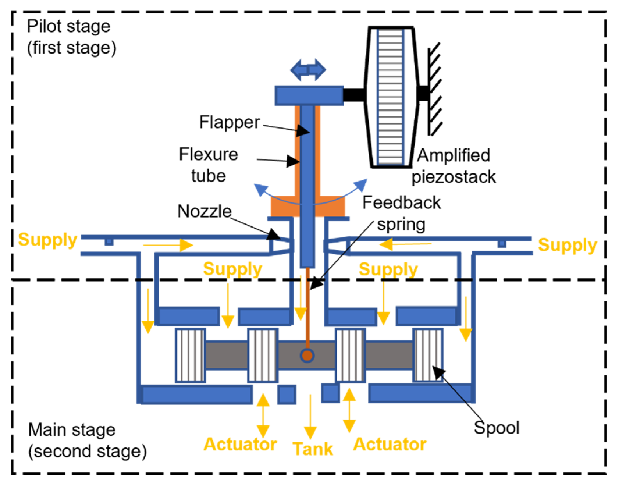
In [
39], a commercially available piezo stack actuator with a mechanical flexure amplification system similar to that shown in
Figure 13 was used in place of a conventional torque motor to move the flapper in a double nozzle-flapper pilot stage, as shown in
Figure 16.
The working principle was very similar to that of a conventional two-stage servovalve. Indeed, the force generated by the voltage applied to the piezo stack actuator moved the flapper, which in turn created a differential pressure at the main spool ends and allowed the main spool to move. The negative values of the operating voltage moved the main spool to the left, while the positive values moved to the right. For a supply pressure of 210 bar, a flow rate of 10.5 L/min was obtained at the maximum input voltage of 35 V from null. In these conditions, the −90 deg phase lag was obtained for a frequency of 284 Hz; the response time was 0.8 ms.
In this design, the use of an amplified piezo stack in place of the torque motor can lead to an increase in the size and weight of the pilot stage, thus affecting the main characteristics of a two-stage servovalve, which are the low weight and small size.
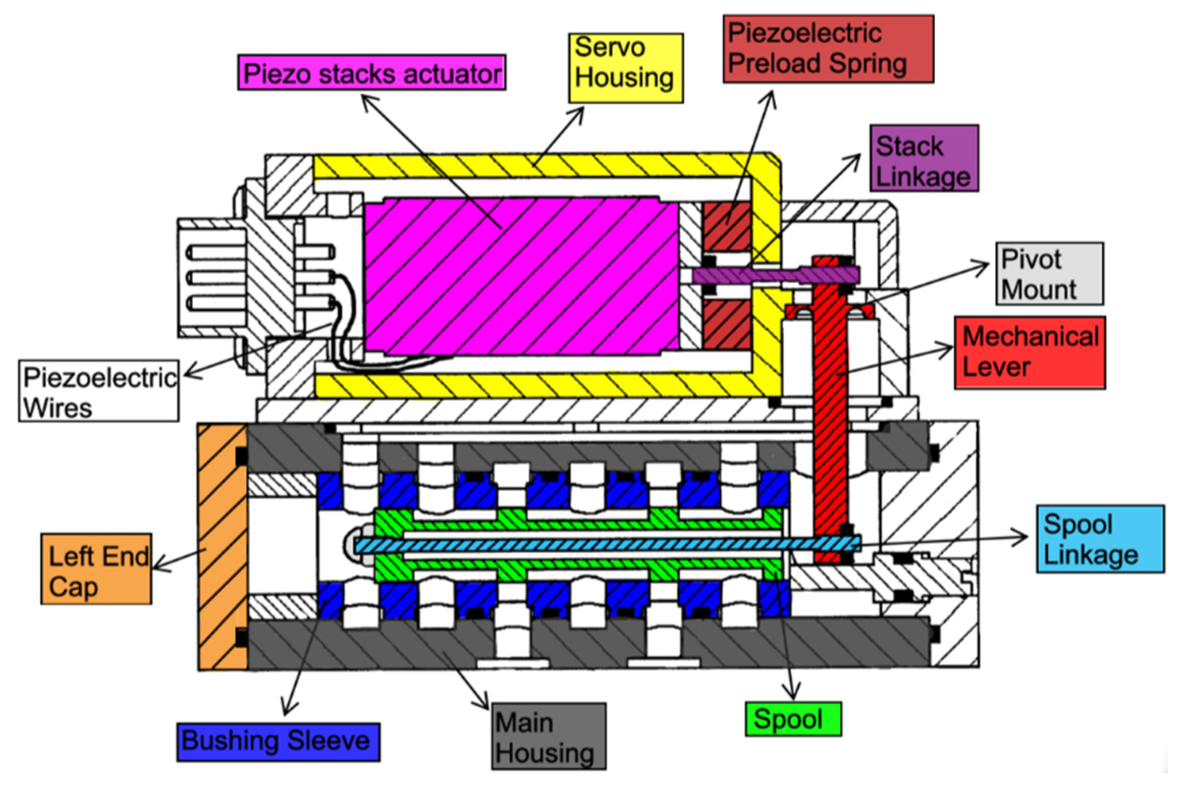
In [
40,
41], a commercially available amplified piezo stack actuator with a diamond amplification mechanism (model NAC2645 produced by Noliac [
23]) was proposed to be used in place of heavier linear force motors for the actuation of a direct drive servovalve, as shown in
Figure 17. A linear variable differential transformer (LVDT) was proposed to be employed to compensate for hysteresis and to achieve closed-loop control.
With the diamond amplification mechanism, any change in the operating temperature will have no effect on the displacement despite stack thermal expansion due to the symmetry of the mechanism [
41]. The diamond amplification mechanism is capable of providing a maximum blocking force of 332 N and producing a maximum free stroke of 0.475 working in both directions [
23]. To cope with the small spool displacement and to achieve high values of flow rate, the slot width of the bushing sleeve was proposed to be taken as equal to 2/3 of the whole perimeter of the spool.
A detailed Simulink model making use of the libraries of Simscape was employed to study the performance of this valve configuration [
42]. A maximum displacement of about 0.45 mm was predicted, very similar to that achievable with linear force motors (±0.5 mm). The simulation results were first obtained with an open-loop control system. Using a large spool, the time interval predicted to reach 90% of the maximum opening was less than 5 ms using an amplifier with a natural frequency of 1400 rad/s. High inlet pressure levels were sustained by the valve, and therefore, high flow rates were achieved (about 70 L/min at 200 bar) in the simulations. The use of closed-loop control allowed hysteresis to be successfully managed. A very good closed-loop frequency response was predicted, the phase shift being −105 deg for a frequency of 100 Hz and an amplitude of 0.4 mm, using an amplifier with 1400 rad/s natural frequency.
The manufacturer advises against exceeding the limit of the actuation force in order to protect the internal mechanism. This limit in the actuation force, which changes with the temperature, being 250 N at 20 °C and 200 N at 50 °C, is sufficiently high enough to allow the opposing forces in a spool valve (i.e., flow forces and friction) to be counteracted; however, this represents a limitation as far as the chip shear capability is concerned, since the force required to shear the contamination particles that can be caught between the edges of a metering section can exceed 200 N [
41]. The cost of the amplified piezo stack actuators with a diamond amplification mechanism is currently high (about EUR 2000) [
23]; however, the cost could be reduced in the future by the large-scale production of these actuators.
5. Servovalves Driven by Bimorph Bender Actuators
To increase the displacement to volume ratio, bimorph (rectangular) benders have been developed by a few manufacturers [
22,
23,
24,
25].
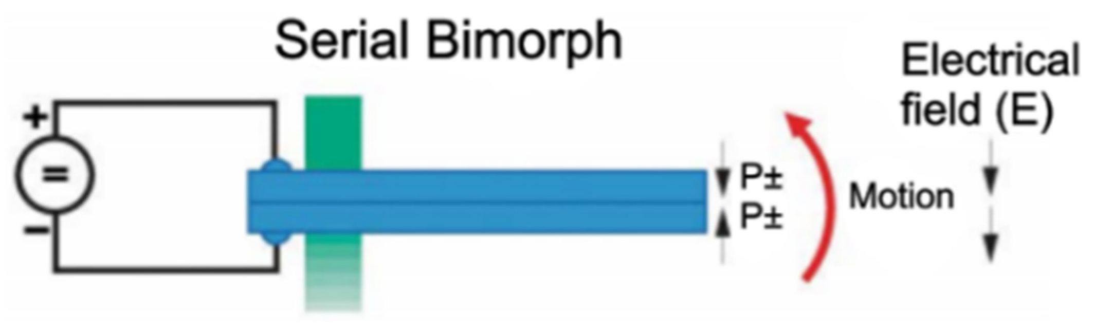
A bimorph bender actuator (also called plate actuator) consists of two or three layers sandwiched between electrodes, as shown in
Figure 18. The piezo layers are operated in opposite mode (contraction/expansion) by being polarized in opposite directions. A layer of a metal alloy can be positioned between the ceramic elements.
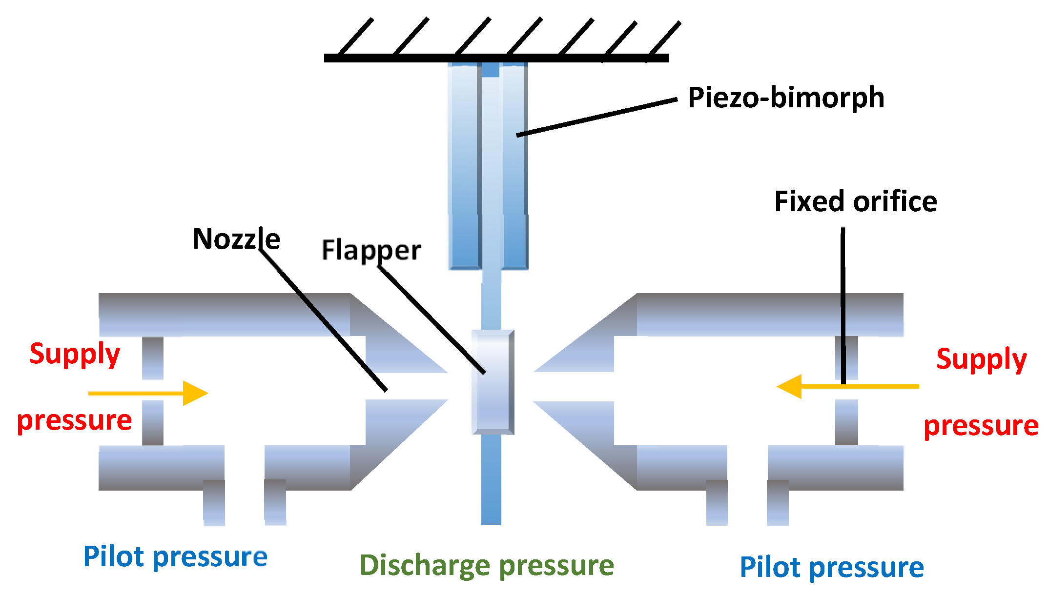
Because of their characteristics (low weight, high displacement and cost-effectiveness), bimorph bender actuators have the potential to replace the torque motor in the pilot stages of servovalves, according to the scheme of
Figure 19 [
44].
The main problem is the very low actuation force generated by these actuators, being of the order of a few Newtons. For example, model CMBP09 produced by Noliac [
23] has a length of 5 cm, a width of 7.8 mm, and a height of 1.8 mm, providing a maximum free stroke of ±635 µm and a maximum blocking force of 2.9 N.
To evaluate the effects of the hydraulic oil upon the piezoelectric bimorph actuator, a Simulink model was used in [
44] to investigate the architecture of
Figure 19. The simulation results showed that at a frequency of 200 Hz, the maximum displacement of the flapper without oil (32.5 μm) was significantly higher than the maximum displacement obtained when the flapper was immersed in oil (5 μm). This is due to the additional mass that the fluid provided to the actuator.
In [
45,
46,
47,
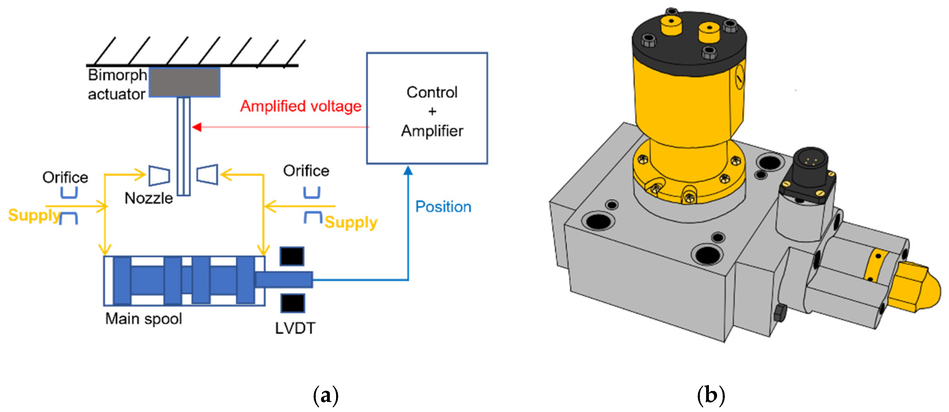
48], bimorph bender actuators were used to actuate the flapper in a complete double nozzle-flapper servovalve (pilot stage + main stage), as shown in
Figure 20a. LVDTs were used to measure the main spool position, thus achieving closed-loop control to cope with the hysteresis of the bimorph benders.
The piezo valve constructed in [
45] is shown in
Figure 20b. It employed a parallel bimorph bender actuator, which provided a free stroke of ±1 mm and a blocking force of 0.35 N for a maximum operating voltage of ±60 V. The test results showed that this piezo valve had a bandwidth of 140 Hz and could pass 7 L/min at a pressure drop of 14 bar. Similar results were also obtained in [
46,
47].
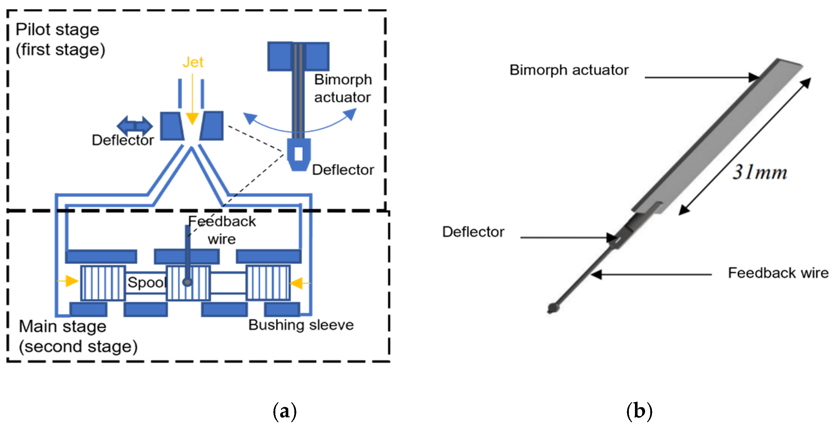
In [
49,
50], a multilayer bimorph actuator was used in place of the torque motor to move the deflector in a prototype of deflector jet piezo valve, as shown in
Figure 21. An existing design of main stage valve body was used (Moog 26 series), fitted with an integrated linear variable differential transformer (LVDT) to measure the spool position. When a voltage was applied to it, the piezoelectric actuator bent and moved the deflector, which, in turn, directed the jet of fluid to one of the two control ports. This created a pressure difference on the spool ends, thus allowing the spool to move in the opposite direction to the movement of the deflector. A feedback wire attached to the rectangular piezoelectric bimorph bender was used to achieve mechanical feedback and generate a restoring force that could center the deflector and stop the spool at a fixed position. The valve showed effectiveness and reliability during operation and good performance levels. The simulation results, predicted using Simulink, were compared to the experimental results. At a supply pressure of 140 bar, the −3 dB bandwidth of the experiment results (≈38 Hz) was 13.6% slower compared to the predictions (≈40 Hz). The −90 deg phase frequency was approximately 50 Hz in both cases. A patent concerning this novel actuation system for pilot stages was recently filed [
51].
6. Servovalves Driven by Ring Bender Actuators
The designs in which a bimorph (rectangular) bender is used to actuate the pilot stage of a two-stage servovalve might have an issue concerning the very low actuation force generated by these piezo actuators. For example, the bimorph bender employed in [
49,
50] had a maximum blocking force of only 1 N. To increase the actuation force, ring benders, which are constructed by a few manufacturers, can be used [
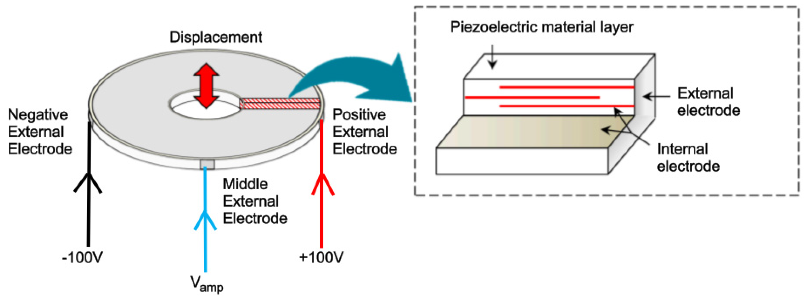
23]. The ring bender has recently become available and is composed of several thin layers of piezoceramic with internal silver palladium electrodes, which, in turn, are connected to external electrodes, as shown in
Figure 22. By applying voltage to the external electrodes, which usually ranges from −100 V to +100 V, the ring bender can deform concavely or convexly [
52,
53]. A ring bender has higher stiffness and higher blocking force than a bimorph actuator of similar size but lower displacement. For example, model CMBR07, produced by Noliac, exhibits a free displacement of ±185 µm and a maximum blocking force of 13 N at a maximum operating voltage of ±100 V [
23].
In [
53], a prototype of double nozzle-flapper pilot stage pilot stage was developed in which two ring benders were mounted with O-rings inside a housing to actuate the flapper, as shown in
Figure 23a. A total of two ring benders were used for redundancy, which is needed in aircraft applications. Experimental tests were performed on the prototype. The flapper stroke was ±50 μm. The maximum flow rate was 0.61 L/min.
In [
54], the application of this novel pilot stage to a typical 4/3 valve was assessed using a detailed Simulink model, which reproduced all of the real phenomena present in such a complex hydraulic system. Step and sinusoidal tests were simulated for a supply pressure of 210 bar, thus predicting the valve potential. It was shown that the interval time necessary to reach 90% of the set point was about 3 ms for a spool position of 0.1 mm, 4 ms for a spool position of 0.6 mm, and 6 ms for a spool position of 1 mm. With regard to the frequency response, at a 100 Hz and ±1 mm amplitude, the phase shift was around −90 deg.
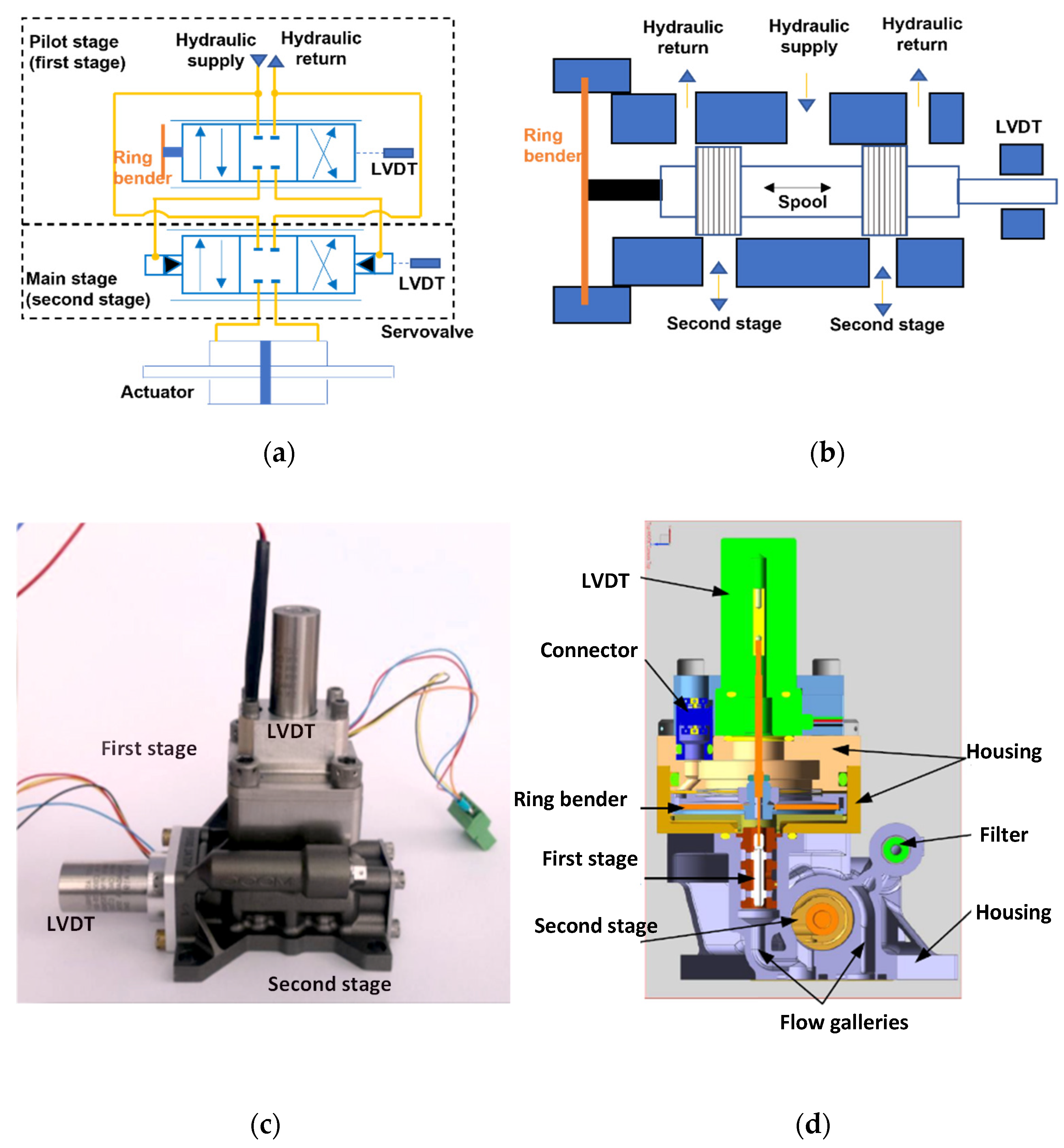
In [
55,
56,
57], a two-stage piezo valve was developed using additive manufacturing. The first stage (i.e., the pilot stage) employed a four-way three-position small spool directly driven by a ring bender, as shown in
Figure 24.
To minimize the internal leakage, a significant overlap was used between the bushing sleeve and the spool lands in the first stage. A conventional main stage was hydraulically connected to the pilot stage, and the main spool was controlled by the flow, which passed through the small spool. A total of two LVDTs were used to measure the ring bender position and the main spool position, respectively. The ring bender was characterized by a maximum displacement equal to ±115 µm and a maximum blocking force equal to ±39 N for a maximum operating voltage of ±100 V. A Simulink model, simulating the amplifier, the first stage and the second stage, was developed and validated against experimental data. The valve worked very well at different operating conditions; at a supply pressure of 210 bar, the −90 deg phase frequency was around 100 Hz.
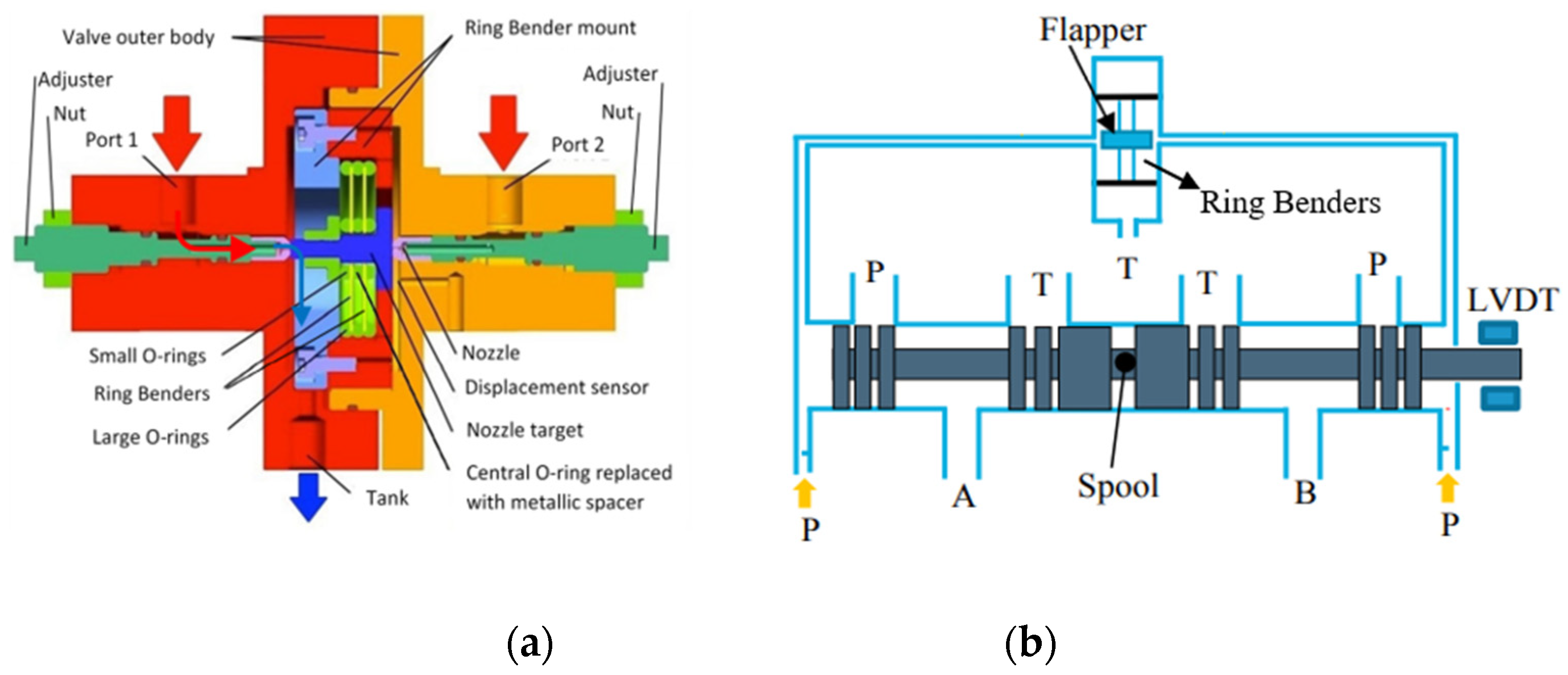
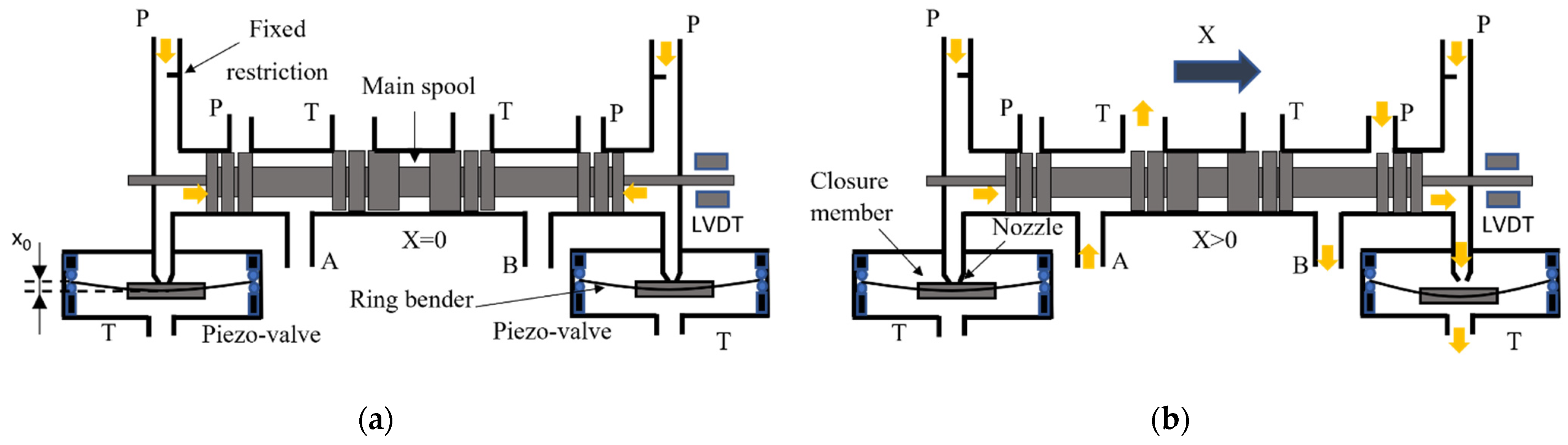
In [
4,
58,
59], a novel pilot stage configuration composed of two normally closed two-way two-position (2/2) valves actuated by two piezoelectric ring benders was developed, as shown in
Figure 25. Again, an LVDT was used to achieve closed-loop control. The differential pressure, which allows the spool to move from its neutral position, was generated by opening and closing the piezo valves. To assess the validity of this design, an experimental prototype of the 2/2 piezo valve was constructed and was experimentally tested in a hydraulic test rig. The step tests performed on the test rig show that the piezo valve had high potential in terms of response speed since the time required for the displacement and for the pilot pressure to change from 10% to 90% of their final values was less than 5 ms. After the experimental validation, a Simulink model was developed to simulate the entire valve. The results of the simulated step tests showed that the response time was very fast, with about 6 ms predicted to reach 90% of the full opening. Concerning the sinusoidal tests, the predicted phase shift was 40.8 deg for an input sine signal with an amplitude of 1 mm and a frequency of 50 Hz, and 117.7 deg for an input sine signal with an amplitude of 1 mm and a frequency of 100 Hz.
The main advantage of this architecture compared to a conventional servovalve is in terms of power consumption. Indeed, common architectures of two-stage servovalves have high internal leakage in the pilot stage. As an example, for an inlet pressure of 210 bar, the quiescent flow in a Moog double nozzle-flapper valve (series 30) is around 0.73 L/min [
60], whilst the leakage flow predicted through each piezo valve, when the spool was in the neutral position (null), was negligible and was equal to 0.029 L/min. This allowed the piezo valve to avoid a power consumption of about 0.4 kW in the neutral position, for a supply pressure of 210 bar. In addition, this novel configuration has the potential to reduce the complexity of the pilot stage because the torque motor is removed.
7. Discussion
A comparison among the main types of piezoelectric actuators (piezo stack, amplified piezo stack, bimorph bender, ring bender) was provided in this paper, highlighting advantages and disadvantages of each type. A piezo stack actuator is fragile with respect to tensile stress; to manage this and to improve its dynamic performance, a correct value of preload must be applied to it. Piezo stacks can be employed to directly drive the spool in single-stage servovalves [
27,
28,
29] or to replace the torque motor in two-stage servovalves [
30,
31,
32]; they can also be used to actuate a moving bushing sleeve in a hybrid direct drive servovalve [
32] or to actuate a moving plate with annular grooves in a novel direct drive valve design [
15]. It was shown that the direct actuation of servovalves using piezo stacks can provide some advantages, such as simplicity, fast response speed, high bandwidth, and high actuation forces (hence, high chip shear force capability). However, the main disadvantages resulting from the use of a piezo stack actuator are the low stroke and high dimensions. This means that a very large stack is needed to achieve high values of flow rate; therefore, a very large valve must be designed. It must also be taken into account that the performance of a piezo stack actuator can be affected by changes in the operating temperature.
To overcome these issues, novel designs of servovalves actuated by piezo stacks with amplification mechanisms have been proposed in the scientific literature. The mechanical amplification, which is obtained through a lever or through a diamond structure (the latter providing temperature compensation), allows higher displacement to be reached but at the expense of the actuation force, which is lower than that provided by a piezo stack. Amplified piezo stacks can replace the torque motor to actuate the pilot stage of servovalves [
39], but this causes an increase in the size of the pilot stage. Alternatively, they can replace heavier linear force motors for the actuation of direct drive servovalves [
35,
36,
37,
38,
40,
41]. The latter solution seems very promising, especially if a temperature independent diamond structure is used [
40,
41]. However, such direct drive valves will have low chip shear force capability because of the limited maximum force exerted by commercially available amplified piezo stacks [
40,
41].
Bimorph (rectangular) benders and ring benders have been suggested by a few authors as substitutes for the torque motor in two-stage servovalves in order to reduce the high complexity of the torque motor assembly. These piezo actuators are smaller than piezo stacks and amplified piezo stacks; therefore, their use will not affect an important characteristic of two-stage servovalves, which is the small size. The application of direct drive servovalves is not possible with these piezo actuators, given their low actuation force. Rectangular benders have been proposed to actuate either the flapper of double nozzle-flapper servovalves [
44,
45,
46,
47,
48] or the deflector of deflector jet servovalves [
49,
50,
51]. However, a ring bender might be preferred over a rectangular bender for the actuation of a pilot stage because of the higher actuation force of the former. Some prototypes have been developed using ring benders to actuate either the flapper of the pilot stage [
53,
54] or a small spool serving as pilot spool [
55,
56,
57]. The results are very satisfactory in terms of performance levels. A novel configuration has also been studied: making use of both two-ring benders and a different configuration for the hydraulic bridge, this novel valve can eliminate internal leakage in the pilot stage while obtaining a good step response and bandwidth [
4,
58,
59].
All piezo actuators suffer from high hysteresis; therefore, closed-loop control systems are mandatory in all configurations to cope with hysteresis. Most of the proposed piezo valves need a position sensor to obtain closed-loop control; only very few configurations make use of mechanical feedback, thus not needing a position sensor [
39,
49,
50,
51].
The characteristics of the piezo valve typologies analyzed in this paper are listed in
Table 2 in order to summarize the advantages and disadvantages of these configurations.
8. Conclusions
The architectures of commercially available servovalves have not substantially changed for many years and, for this reason, one could think that no great leaps can be made to improve these valves. Nevertheless, these valves have a few problems that have not been solved yet, such as the high complexity of the torque motor, the high internal leakage in the pilot stage concerning two-stage valves, and the large size and weight concerning direct drive valves.
The use of piezoelectric actuators could be instrumental in solving these issues, taking advantage of the fast response and simplicity of these actuators. The main drawbacks could be the high hysteresis (up to 20%) and sensitivity to creep of these actuators.
In this paper, a detailed review of novel servovalve architectures actuated by different types of piezo actuators was provided. Advantages and disadvantages of each configuration were discussed in detail. These novel piezo valve configurations showed that the piezoelectric actuation might have an important role in future designs of servovalves, with the potential to improve their response speed. A crucial factor will be the cost of these technical solutions; in fact, the price of piezo stacks and amplified piezo stacks is still high at the moment. However, the cost could be reduced in the future by the large-scale production of these actuators. Crucial factors will also be the reliability and resistance over time of these novel architectures, which could be affected by hysteresis and creep.


 ,
, 


