1. Introduction
The modular multilevel converter (MMC), first proposed in [
1,
2], has been increasingly attracting attention especially in high- and medium-voltage applications [
3,
4,
5] and grid-connected applications owing to its excellent characteristics [
6,
7,
8,
9]. Furthermore, the MMC technology has a bright future in renewable energy systems (RESs) due to its many advantages [
10]. Furthermore, with the recent advances in supercapacitor manufacturing [
11,
12,
13] the MMC technology is gaining much more attention. In recent years, intensive studies have been performed to enhance the efficiency of the MMC [
6,
14]. However, the precharging start-up control, which is a major technical problem, yet remains one of the least mentioned issues [
15]. The reason why the start-up control is considered a major technical challenge arises from the fact that, unlike the conventional voltage source converters, where DC bus capacitors are centralized, in the MMC, all the submodules’ capacitors are distributed in a dispersed manner [
16], and they need to be smoothly precharged to their rated voltage level during the converter start-up process before entering the normal operation state [
17]. Furthermore, the submodules’ capacitors’ total charging time needs to be minimized as much as possible, so that the overall time of the start-up process decreases and the MMC enters the normal operation phase faster.
In the previous literature, various MMC start-up methods were suggested. In [
1,
17], the proposed start-up method depended on charging the submodules’ capacitors one by one. A high-voltage DC circuit breaker was used in conjunction with an auxiliary DC power supply, whose value was the same as the rated voltage of the submodule’s capacitor in normal operation; however, despite being a straightforward method, its main disadvantages were extending the charging time, and the existence of a high-voltage DC circuit breaker contributed to increasing the overall cost of this method [
18]. In [
19], it was suggested that at each submodule, a charging circuit be placed where this circuit consists of a DC power supply and four thyristors. The aforementioned thyristors would be triggered in a synchronized manner, which would lead to charging all the the submodules’ capacitors together. The main advantage of this method is the reduction of the charging time; however, the main downfall would be the added cost to the system due to the control complexity. In [
20], a boost circuit was presented to completely precharge the submodule’s capacitors. However, in high-voltage applications, the insulation specifications of the external low-voltage DC power supply and blocking diode utilized by this boost circuit are more rigorous, increasing the cost of the equipment in this system. In [
21], a new start-up technique was introduced where, with each submodule, there was an arrangement of a resistor in parallel with a switch, and this arrangement was connected in series to the submodule. The main merit of this newly introduced arrangement is the ability to insert or bypass the resistor using the switch. As a result, the submodules could be charged in succession from the DC main supply. Furthermore, this method does not require an additional DC power supply. The main downfall of this method is the ohmic losses introduced during the precharging of the submodule’s capacitors. A similar approach to this method was employed in [
22].
In [
18], the concept of splitting the precharging process into two stages, the first being the uncontrollable stage and the second the controllable stage, was introduced. From the moment the aforementioned concept was introduced till now, it has been widely adopted in nearly all the literature related to the MMC’s start-up. In [
18], a new start-up method to charge the MMC from the AC grid was proposed where the diode bridge rectifier was connected to the MMC’s DC bus, and this rectifier was in turn connected to the AC grid. In the first stage, the charging of the DC bus capacitor and the MMC’s submodules’ capacitors was performed through the rectifier to the voltage levels
and
, respectively, while limiting the inrush currents by the resistors connected in series, which were bypassed after the charging process after the first stage was completed. For the second stage, by slowly reducing the number of inserted MMC submodules and the duty of the PWM working submodule, the submodules’ capacitors could be charged simultaneously from
till
while effectively suppressing the surge in the arm currents. The main advantage of using this method is that it eliminates the need for a DC circuit breaker or an auxiliary DC source. Furthermore, in [
14,
23], by progressively decreasing the number of inserted submodules, the precharging of the MMC’s submodules’ capacitors was realized.
where:
-
DC Link voltage.
- N
Number of submodules per arm.
Nonetheless, all these aforementioned methods are open-loop-based approaches, meaning that the current throughout the precharging process is uncontrollable. Accordingly, these open-loop-based approaches are very dependent on the circuit parameters, which can lead to overcurrent problems when unintended disruptions or parameter changes are present. In [
24], the first start-up method based on a closed-loop approach was introduced, and it was applied to a three phase back-to-back MMC system being charged from an AC grid. For the rectifier side, a double-closed-loop decoupling control strategy was utilized to improve the response speed and control precision of the current control. On the other hand, the inverter side of the BTB MMC started charging while the number of submodules was reduced slowly in order to suppress the output charging current. In [
15,
25,
26], a closed-loop control method was suggested where the precharging currents could be regulated—by means of feedback control—to a constant value only during the second stage, which resulted in linearly charging the submodules’ capacitors, which reduced the start-up time. In [
16], a closed-loop-based precharging method that made use of the deadbeat predictive current control was introduced, where parameter tuning was not mandatory.
2. Desired Start-Up Objectives
(1) The first objective is charging the MMC’s submodules’ capacitors with a predetermined current having a constant value during the entire start-up process (uncontrollable phase and controllable phase), which would lead to decreasing the start-up time drastically (the resulting start-up time in this case is uncontrolled, but could be easily evaluated);
(2) The second objective is the ability to set a specific start-up time value for the entire start-up process of the MMC (the resulting charging current in this case could not be set to a specific value, but could be easily evaluated and kept at a constant value throughout the entire start-up process).
3. Total Charging Time for the MMC’s Submodules’ Capacitors
Calculating the total charging time is very important for the proposed start-up method. In [
26], it was proven that it is possible to approximate the MMC start-up circuit from a second-order system to a first-order RC circuit. Therefore, based on that approximation, applying the law of conservation of energy, and assuming that there is no power loss during the charging process, Equation (
1) is obtained [
15,
25,
27]:
where:
The circulating—charging—current which is kept at a predetermined constant value of “” throughout the entire charging process.
Initial voltage of the submodule’s capacitor for the second—controllable—start-up phase which is also the submodule’s capacitor voltage at the peak current of the last stage in the sequential capacitors charging method during the first—uncontrollable—phase of the start-up process.
Rated submodule’s capacitor voltage.
The time required for charging the capacitors from a certain initial voltage to their rated voltage for the MMC to enter the normal operation phase.
The time at which the circulating-charging-current reaches its peak value at the final stage of the sequential capacitors charging method during the first—uncontrollable—phase of the start-up process.
The total time required for completing the start-up process of the MMC.
4. The Proposed Start-Up Method for the Single-Phase MMC
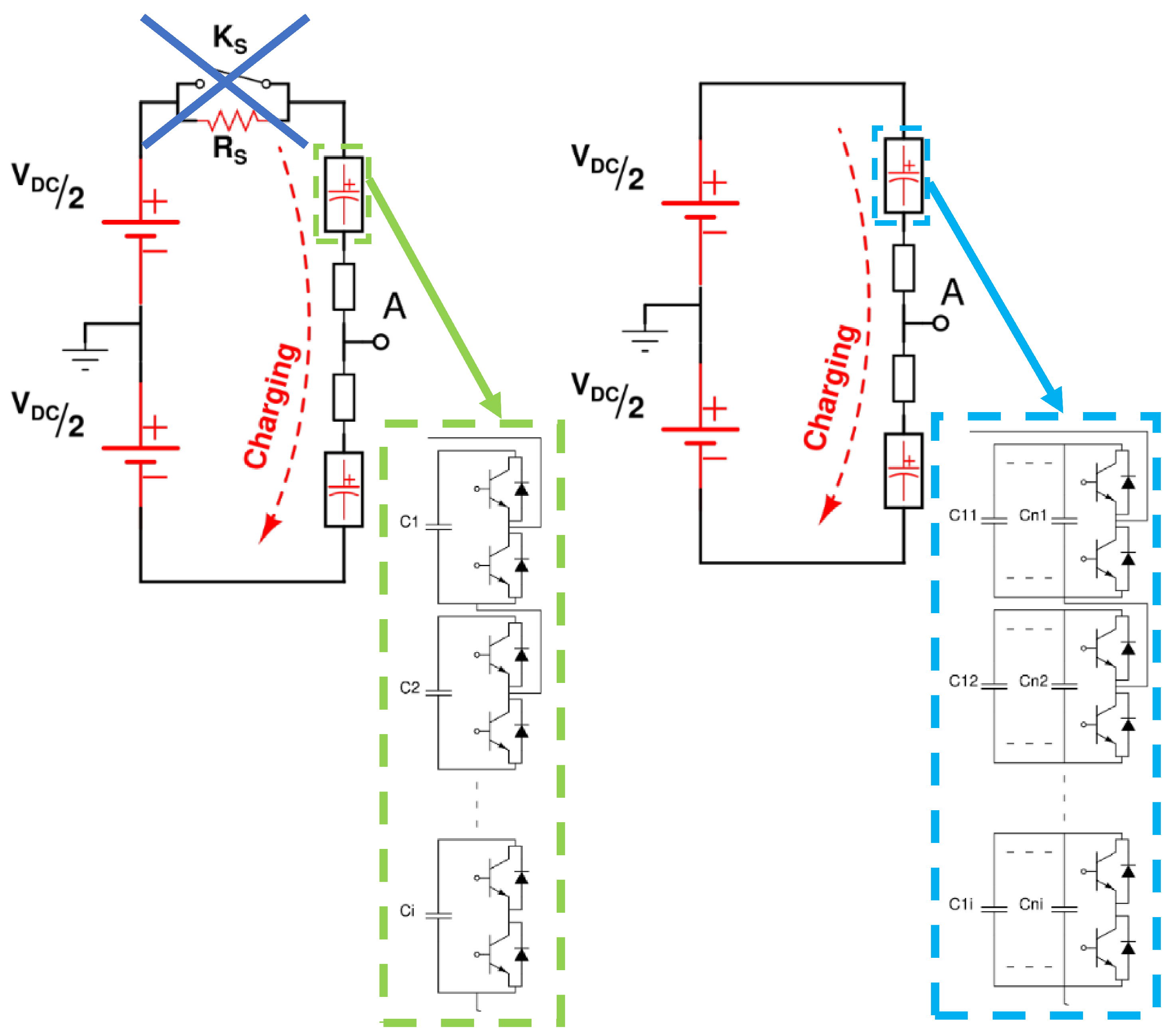
(1) The proposed start-up method utilizes, during the first—uncontrollable—phase of the start-up process, the sequential capacitors’ charging method along with the capacitor bank submodule topology, as shown in
Figure 1, resulting in reducing the peak current without the need for the contactor–resistor arrangement [
26]. Furthermore, the charging current is kept at a constant value throughout the entire phase, which is mainly the desired predetermined peak current value.
(2) After inserting the last stage of the capacitor bank at each submodule during the aforementioned phase, the voltage at the time corresponding to the occurrence of the predetermined peak current should be calculated, because this voltage would be considered as the initial voltage of the second—controllable—phase “” of the start-up process, and if this voltage is at an acceptable level for the gate drive circuits of the transistors of the submodules, then this would be the perfect moment to begin the second—controllable—phase of the start-up process.
Notice that:
(a)
Table 1 is a summary of all the equations that are used in the proposed start-up method, while
Figure 2 is the flowchart representing the the proposed start-up process for the single-phase MMC;
(b) Regarding the aforementioned flowchart, the 9th step is very important to ensure a smooth transition between the two start-up phases while keeping the circulating charging current constant, because at this step, the time “” is calculated; furthermore, this instance of time is of great significance as it would be used in the 10th step to calculate the submodule’s capacitor voltage “” at the peak current of the last inserted stage during the first phase of the start-up process, which is a critical voltage value for calculating the total charging time required.
Furthermore, represents the time value at which the closed-loop precharge control is activated;
(3) The proposed start-up method employs a closed-loop precharge control [
15,
25,
27] during the second—controllable—phase of the start-up process, thereby the circulating charging current is also kept at a predetermined design-based value during the second phase;
(4) This article specifically introduces a suitable strategy from the 8th step of the flowchart till the 11th step to combine the capacitor bank-based MMC’s submodule topology along with the sequential capacitors’ charging methods during the uncontrolled start-up phase and the closed-loop precharging control during the controllable start-up phase.
where:
| R | The MMC’s upper and lower arms’ resistance. |
| L | The MMC’s upper and lower arms’ inductance. |
| load displacement angle. |
| Load resistance. |
| Load reactance. |
| Damped natural frequency. |
| Undamped natural frequency. |
| f | Frequency of the required ac output waveform in hertz. |
| Angular frequency of the required ac output waveform. |
| Damping coefficient. |
| Damping ratio. |
| The initial capacitor current. |
| Peak current occurring during the first stage of the proposed methods. |
| The initial submodule capacitor voltage. |
| Average submodule capacitor voltage. |
| Total submodule’s capacitance. |
| Total minimum submodule capacitance. |
| Ripple factor of the SM capacitor voltage, which lies between 0 to 0.5. |
| Single phase apparent power. |
5. Deducing the Relation among the Total Charging Time of the Proposed Method, the Total Number of Stages, and the Total Submodule’s Capacitance
Using the curve fitting toolbox in MATLAB, Equation (
3) for the total charging time in terms of total submodule’s capacitance and total number of stages was obtained and
Table 2 shows the polynomial coefficients of Equation (
3).
where:
The significance of Equation (
3) is that if the start-up time was a design constraint, and given a certain total submodule capacitance value, then using any numerical method for solving Equation (
3), the number of stages could be estimated.
The number of stages is of great importance because, based on it:
(1) The capacitor bank at each submodule would be designed;
(2) All the calculations of the insertion time of each stage of the capacitor bank per submodule during the first—uncontrollable—start-up phase were performed.
Therefore, the result of the proposed method is the ability to specifically control the start-up time of the MMC.
Table 1.
Summary of the equations used in the proposed start-up method [
26].
Table 1.
Summary of the equations used in the proposed start-up method [
26].
| | Underdamped
Response | Overdamped
Response | Critically Damped
Response |
|---|
Start-up
(circulating)
current | | | |
Time of
peak
current | | | |
Submodule
capacitor
voltage | | | |
Relation among the peak current “”,
number of stages “n”,
and total submodule capacitance “” | (13) |
MMC submodule minimum total capacitance
selection criteria | |
| where: |
| | | |
| | | |
| | | |
| | | |
Table 2.
Polynomial coefficients of Equation (
3).
Table 2.
Polynomial coefficients of Equation (
3).
| = 0.3489 | = 0.07184 | = −0.06003 |
| = −0.05051 | = −0.02419 | = 0.04051 |
| = 0.385 | = 0.0456 | = −0.006539 |
| = 0.01118 | = −0.04163 | = 0.02641 |
| = −0.07829 | = 0.02523 | = −0.01608 |
6. Outcomes of the Proposed Start-Up Method
(1) The overall result of this method is that the circulating charging current is kept at a predetermined constant value during the entire start-up process, which leads to decreasing the start-up time drastically;
(2) The introduced method is immune to any parameter deviations, and that is inherited from the robustness of the closed-loop control;
(3) It is applicable to any MMC’s application, as it is independent of the number of submodules; also, to ensure equal charging for all the submodules’ capacitors, a voltage balancing control is utilized;
(4) The proposed method is very useful because getting rid of the starting resistance would eliminate the thermal resistive losses that occur during the 1st uncontrollable stage of the precharging process;
(5) The 4D plot in
Figure 3 was created using a MATLAB code to show the effectiveness of the introduced method and
Table 3 shows the base values used in the per-unit calculations.
The aforementioned 4D plot reveals an important feature of the proposed method, that is as the total number of stages of capacitors at each submodule increases, the peak current (which would be kept constant during the entire start-up process) decreases “
” [
26], and the total time of charging (the time for the entire start-up process) decreases while the total submodule’s capacitance is kept constant. “
”;
(6) One of the most important features of the proposed method is the ability to set a specific start-up time value for the start-up process of the MMC using Equation (
3).
7. Case Study and Simulation Validation
Since this article is considered to be a continuation of the MMC capacitor bank-based submodule topology accompanied by the sequential capacitors’ charging methods during the uncontrolled start-up stage. both of which where first introduced in [
26], it is most convenient to consider the same case study with the same system parameters used in [
26], to validate the newly proposed start-up method.
The case study that was discussed in [
26] had the following design specifications:
Total required capacitance = 8400 µF.
The desired peak current = 38.5 A.
Using Equation (13) from
Table 1, the resulting number of stages = 7.1797 ≈ 8 stages.
After approximating the calculated number of stages to the nearest whole integer, the the peak current would be less than 38.5 A, because as shown in
Figure 3, “
”.
In the presented case study, the peak current was the design constraint, so Equation (13) from
Table 1 was used to ensure that the peak current during the entire start-up process would be kept constant at the desired peak current value. In case that the total start-up time was the design constraint, then Equation (
3) would be used to ensure that the start-up time would not exceed the desired value.
Implementing the Proposed Start-Up Method
In order to verify the effectiveness of the proposed start-up method (sequential capacitor charging coupled with closed-loop precharge control) against the conventional start-up method, MATLAB’s Simulink software was used to simulate the operation of the single-phase MMC inverter—shown in [
26]—during both phases of the start-up process using both the conventional start-up method and the proposed start-up method and the control gain parameters in
Table 4 were used.
The simulation results representing the circulating current and the submodule’s capacitor voltage are shown in the following
Figure 4,
Figure 5 and
Figure 6.
An important note is that during the entire start-up process (Phases 1 and 2), the output AC current value was zero because the load was disconnected, so , , and were all equal to each other, and in this case, the circulating current could be measured directly.
In
Figure 4, the typical MMC submodule’s topology is used, where there is a single capacitor of 8400
F at each submodule. The conventional start-up method was employed where, for the first—uncontrollable—phase of the start-up process, in order to limit the value of the peak current so as not to exceed the maximum value (38.5 A), a starting resistance of “4
” was used. In the second—controllable—phase of the start-up process, the closed-loop precharging control was employed, and the value of the reference circulating current was taken as the same as the peak current value that occurred during the first phase (38.48 A) in order to make sure that the current never—in both phases of the start-up process—exceeded the maximum value (38.5 A).
As a result of the conventional start-up process employed, the process of charging all the submodules to their rated value “” would be completed after “ s”.
On the contrary, in
Figure 5 and
Figure 6, the proposed MMC’s submodule topology in [
26] was employed, where there was a capacitor bank consisting of eight stages, all of which had an overall capacitance 8400
F at each submodule. The sequential capacitors’ charging method [
26] was utilized for the first—uncontrollable—phase of the start-up process, where the charging current was kept constant, as shown in
Figure 6, at 37.57 A, which is below the maximum value (design constraint) of 38.5 A. In the second—controllable—phase of the start-up process, the closed-loop precharging control was employed, and the value of the reference circulating current was taken as the same value of the current that was kept constant during the first phase of the start-up process (37.57 A). As a result of the proposed start-up method, once the capacitors start charging the circulating charging current starts increasing till it reaches a predetermined peak value (based on the given design constraint), after which it is kept constant during both phases until all the submodules’ capacitors are fully charged to their rated value as in
Figure 5 “
”. This charging process would be completed after “
s”, after which the circulating charging current would begin decreasing as the MMC enters the normal operation phase.
Notice that the total start-up time when using the conventional start-up method was s, while when using the proposed start-up method, this time decreased to 0.124 s, which is about a 72.134% reduction from the largest start-up time (0.445 s).
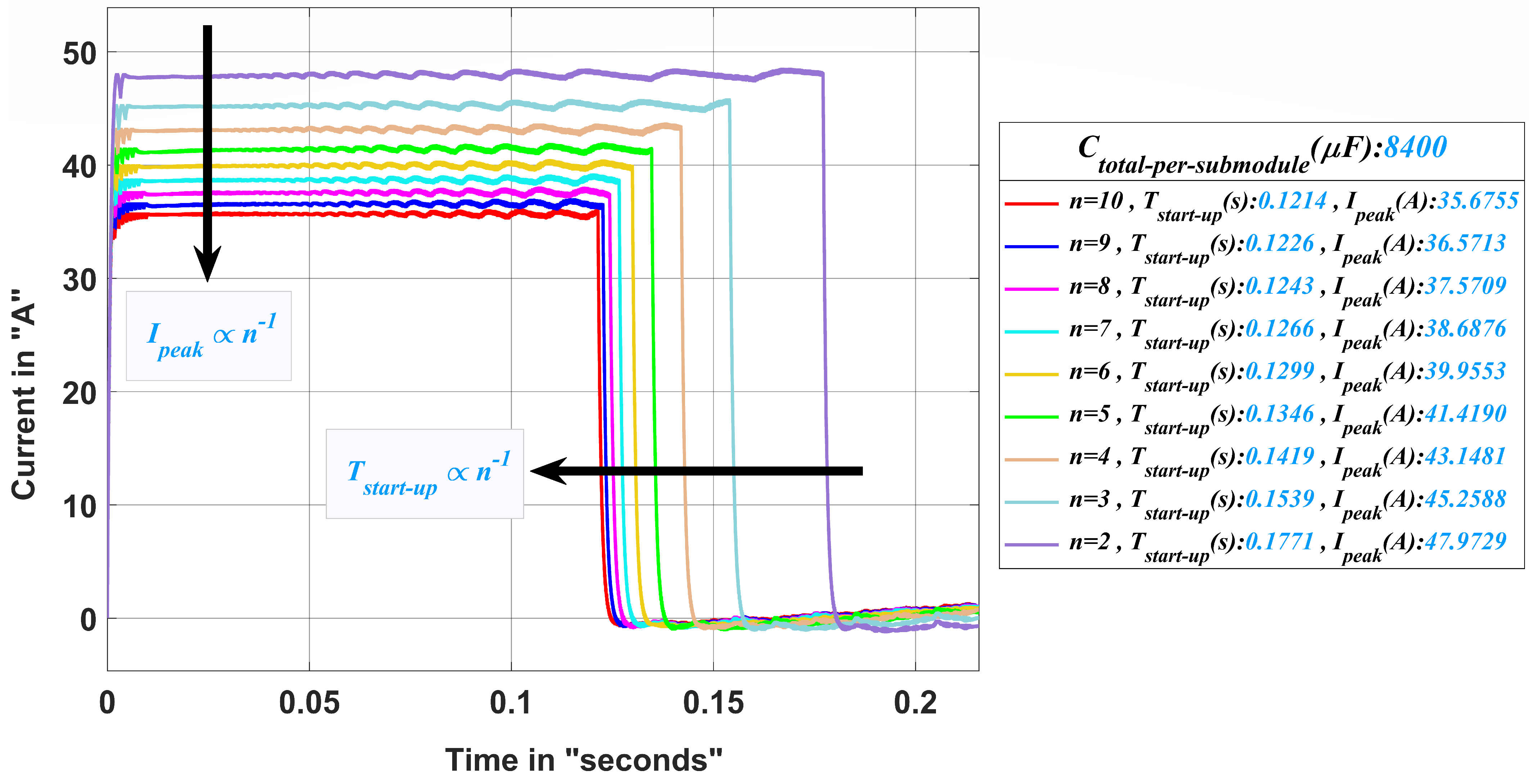
Furthermore, after it was proven that the proposed start-up method had more advantages over the conventional start-up method, the proposed start-up method was utilized in
Figure 7, and it was observed that each time the number of stages of the capacitor bank per submodule was increased, the peak current decreased and vice versa.
Also, upon increasing the number of stages, the total start-up time decreased and vice versa. These two observations were already revealed by the 4D plot in
Figure 2.
Basically, to summarize the concept of this start-up method, referring to the flowchart in
Figure 2, in the first step and second step, the capacitance of each submodule was replaced with an equivalent capacitor bank, and this capacitor bank consisted of a specific number of stages where each stage had a capacitor with a specific capacitance, and the main idea of the proposed method was to determine the number of stages of each capacitor bank; this number was chosen based on whether there was a strong need to limit the charging current to a specific value while having no interest in keeping the total start-up time bounded to a certain value, then Equation (13) would be used or the number of stages chosen in order to achieve a specific total start-up time with no regards whatsoever about the value of the resulting charging current, then Equation (
3) would be used. Keep in mind that regardless of the method by which the number of stages is chosen, the resulting charging current is kept constant during the entire start-up process. Furthermore, after the successful calculation of the number of stages, the following steps from the third step till the seventh step are the steps concerning the application of the algorithm explained in [
26] in order to calculate the time of insertion for each stage of each capacitor bank, then from the eighth step till the eleventh step, as stated earlier, this is the strategy by which the second phase of the start-up process is activated.
8. Conclusions
In this paper, a new method for precharging the single-phase MMC was introduced to reduce the total time for precharging the submodules’ capacitors and limiting the inrush current during the uncontrolled start-up phase without the use of the traditional resistor–contactor arrangement.
The usefulness of the proposed start-up method arises from the fact that as the number of stages of the capacitor bank at each submodule increases, the peak current throughout the entire start-up process decreases, accompanied by a reduction in the total time of the whole start-up process.
The newly proposed method showed great potential, as it successfully precharged the MMC submodules’ capacitors with a constant predetermined current value throughout the entire start-up process, which resulted in reducing the total charging time significantly by 72.134% in comparison with the conventional method.
A detailed design algorithm of the proposed start-up method was introduced. The feasibility of this method was shown by simulations using MATLAB’s Simulink, making it a viable alternative to the traditional start-up method.
9. Future Work
The suggested start-up approach in this paper dealt with the precharging of a single-phase MMC from the DC grid, so finding an adequate strategy to apply this procedure to a multiphase MMC would be useful.
Furthermore, finding a suitable way in order to utilize the method represented here to precharge a single- or three-phase MMC from an AC grid would be of great significance.
Author Contributions
Conceptualization, A.A.A.; Data curation, A.A.A.; Formal analysis, A.A.A.; Funding acquisition, W.A.M.G.; Investigation, A.A.A.; Methodology, W.A.M.G.; Project administration, W.A.M.G.; Resources, A.A.A.; Software, A.A.A.; Supervision, W.A.M.G.; Validation, A.A.A.; Visualization, A.A.A.; Writing—original draft, A.A.A.; Writing—review & editing, W.A.M.G. All authors have read and agreed to the published version of the manuscript.
Funding
This research received no external funding.
Acknowledgments
The authors are grateful for the facilities provided by the Arab Academy for Science, Technology, and Maritime Transport in Alexandria, Egypt, as well as the staff’s and administration’s efforts and encouragement.
Conflicts of Interest
The authors declare that they have no known competing financial interest or personal relationships that could have appeared to influence the work reported in this paper.
References
- Lesnicar, A.; Marquardt, R. An innovative modular multilevel converter topology suitable for a wide power range. In Proceedings of the 2003 IEEE Bologna Power Tech Conference Proceedings, Bologna, Italy, 23–26 June 2003; pp. 1–6. [Google Scholar]
- Lesnicar, A.; Marquardt, R. A new modular voltage source inverter topology. In Proceedings of the EPE, Toulouse, France, 2–4 September 2003; pp. 1–6. [Google Scholar]
- Glinka, M.; Marquardt, R. A new AC/AC multilevel converter family. IEEE Trans. Ind. Electron. 2005, 52, 662–669. [Google Scholar] [CrossRef]
- Marquardt, R. Modular Multilevel Converter: An universal concept for HVDC-Networks and extended DC-Bus-applications. In Proceedings of the The 2010 International Power Electronics Conference—ECCE ASIA, Sapporo, Japan, 21–24 June 2010; pp. 502–507. [Google Scholar]
- Debnath, S.; Qin, J.; Bahrani, B.; Saeedifard, M.; Barbosa, P. Operation, control, and applications of the modular multilevel converter: A review. IEEE Trans. Power Electron. 2015, 30, 37–53. [Google Scholar] [CrossRef]
- Antonopoulos, L.A.; Nee, H.-P. On dynamics and voltage control of the modular multilevel converter. In Proceedings of the 2009 13th European Conference on Power Electronics and Applications, Barcelona, Spain, 8–10 September 2009; pp. 1–10. [Google Scholar]
- Rohner, S.; Bernet, S.; Hiller, M.; Sommer, R. Modulation, Losses and Semiconductor Requirements of Modular Multilevel Converters. IEEE Trans. Ind. Electron. 2010, 57, 2633–2642. [Google Scholar] [CrossRef]
- Hagiwara, M.; Akagi, H. Control and experiment of pulse-width modulated modular multilevel converters. IEEE Trans. Power Electron. 2009, 24, 1737–1746. [Google Scholar] [CrossRef]
- Munch, P.; Gorges, D.; Izak, M.; Liu, S. Integrated Current Control, Energy Control and Energy Balancing of Modular Multilevel Converters. In Proceedings of the IECON 2010—36th Annual Conference on IEEE Industrial Electronics Society, Glendale, AZ, USA, 7–10 November 2010; pp. 150–155. [Google Scholar]
- Priya, M.; Ponnambalam, P.; Muralikumar, K. Modular-multilevel converter topologies and applications—A review. IET Power Electron. 2019, 12, 170–183. [Google Scholar] [CrossRef]
- Yedluri, A.K.; Anitha, T.; Kim, H.-J. Fabrication of Hierarchical NiMoO4/NiMoO4 Nanoflowers on Highly Conductive Flexible Nickel Foam Substrate as a Capacitive Electrode Material for Supercapacitors with Enhanced Electrochemical Performance. Energies 2019, 12, 1143. [Google Scholar] [CrossRef] [Green Version]
- Yedluri, A.K.; Araveeti, E.R.; Kim, H.-J. Facilely Synthesized NiCo2O4/NiCo2O4 Nanofile Arrays Supported on Nickel Foam by a Hydrothermal Method and Their Excellent Performance for High-Rate Supercapacitance. Energies 2019, 12, 1308. [Google Scholar] [CrossRef] [Green Version]
- Kumar, Y.A.; Kumar, K.D.; Kim, H.-J. Reagents assisted ZnCo2O4 nanomaterial for supercapacitor application. Electrochim. Acta 2020, 330, 135261. [Google Scholar] [CrossRef]
- Peng, H.; Hagiwara, M.; Akagi, H. Modeling and analysis of switching-ripple voltage on the DC link between a diode rectifier and a modular multilevel cascade inverter (MMCI). IEEE Trans. Power Electron. 2013, 28, 75–84. [Google Scholar] [CrossRef]
- Li, B.; Xu, D.; Zhang, Y.; Yang, R.; Wang, G.; Wang, W. Closed-loop precharge control of modular multilevel converters during start-up processes. IEEE Trans. Power Electron. 2015, 30, 524–531. [Google Scholar] [CrossRef]
- Wang, J.; Tang, Y.; Qi, Y.; Lin, P.; Zhang, Z. A Unified Startup Strategy for Modular Multilevel Converters with Deadbeat Predictive Current Control. IEEE Trans. Ind. Electron. 2021, 68, 6401–6411. [Google Scholar] [CrossRef]
- Marquardt, R.; Lesnicar, A. New concept for high voltage—Modular multilevel converter. In Proceedings of the IEEE PESC, Aachen, Germany, 20–25 June 2004; pp. 1–5. [Google Scholar]
- Shi, K.; Shen, F.; Lv, D.; Lin, P.; Chen, M.; Xu, D. A novel start-up scheme for modular multilevel converter. In Proceedings of the 2012 IEEE Energy Conversion Congress and Exposition (ECCE), Raleigh, NC, USA, 15–20 September 2012; pp. 4180–4187. [Google Scholar]
- Xu, J.; Zhao, C.; Zhang, B.; Lu, L. New Precharge and Submodule Capacitor Voltage Balancing Topologies of Modular Multilevel Converter for VSC-HVDC Application. In Proceedings of the 2011 Asia-Pacific Power and Energy Engineering Conference, Wuhan, China, 25–28 March 2011; pp. 1–4. [Google Scholar] [CrossRef]
- Tian, K.; Wu, B.; Du, S.; Xu, D.; Cheng, Z.; Zargari, N.R. A Simple and Cost-effective Precharge Method for Modular Multilevel Converters by Using a Low-Voltage DC Source. IEEE Trans. Power Electron. 2016, 31, 5321–5329. [Google Scholar] [CrossRef]
- Das, A.; Nademi, H.; Norum, L. A method for charging and discharging capacitors in modular multilevel converter. In Proceedings of the IECON 2011—37th Annual Conference on IEEE Industrial Electronics Society, Melbourne, VIC, Australia, 7–10 November 2011; pp. 1058–1062. [Google Scholar]
- Xue, Y.; Xu, Z.; Tang, G. Self-Start Control With Grouping Sequentially Precharge for the C-MMC-Based HVDC System. IEEE Trans. Power Deliv. 2014, 29, 187–198. [Google Scholar] [CrossRef]
- Qin, J.; Debnath, S.; Saeedifard, M. Precharging strategy for soft start-up process of modular multilevel converters based on various SM circuits. In Proceedings of the 2016 IEEE Applied Power Electronics Conference and Exposition (APEC), Long Beach, CA, USA, 20–24 March 2016; pp. 1528–1533. [Google Scholar]
- Yu, Y.; Ge, Q.; Lei, M.; Wang, X.; Yang, X.; Gou, R. Pre-charging control strategies of modular multilevel converter. In Proceedings of the 2013 International Conference on Electrical Machines and Systems (ICEMS), Busan, Korea, 26–29 October 2013; pp. 1842–1845. [Google Scholar] [CrossRef]
- Li, B.; Zhang, Y.; Xu, D.; Yang, R. Start-up control with constant precharge current for the modular multilevel converter. In Proceedings of the 2014 IEEE 23rd International Symposium on Industrial Electronics (ISIE), Istanbul, Turkey, 1–4 June 2014; pp. 673–676. [Google Scholar] [CrossRef]
- Ghoneim, W.A.M.; Aziz, A.A. Sequential Capacitors Charging Methods During Single Phase Modular Multilevel Converter Uncontrolled Start-Up Pre-Charging Phase. IEEE Access 2020, 8, 209043–209054. [Google Scholar] [CrossRef]
- Yang, X.; Chen, H.; Shi, J.; Hu, W.; Wang, L.; Liu, J.; Hu, P. A novel precharge control strategy for modular multilevel converter. In Proceedings of the 2015 IEEE PES Asia-Pacific Power and Energy Engineering Conference (APPEEC), Brisbane, Australia, 15–18 November 2015; pp. 1–5. [Google Scholar]
| Publisher’s Note: MDPI stays neutral with regard to jurisdictional claims in published maps and institutional affiliations. |
© 2021 by the authors. Licensee MDPI, Basel, Switzerland. This article is an open access article distributed under the terms and conditions of the Creative Commons Attribution (CC BY) license (https://creativecommons.org/licenses/by/4.0/).


