Article

Stability Domain Analysis and Enhancement of Squirrel Cage Induction Generator Wind Turbines in Weak Grids

by
Jonathan Devadason
1,*,
Paul S. Moses
1 and
Mohammad A. S. Masoum
2
1
School of Electrical and Computer Engineering, The University of Oklahoma, Devon Energy Hall, 110 W. Boyd St., Norman, OK 73019, USA
2
Department of Engineering, Utah Valley University, 800 West University Parkway, Orem, UT 84058, USA
*
Author to whom correspondence should be addressed.
Energies 2021, 14(16), 4786; https://doi.org/10.3390/en14164786
Submission received: 24 June 2021 / Revised: 29 July 2021 / Accepted: 29 July 2021 / Published: 6 August 2021

Abstract

:
There are significant concerns regarding the stability of increased wind power generation in weak power grids. This paper investigates and improves the stability of Wind Turbine Squirrel Cage Induction Generators (WT-SCIGs) with series compensation and weak interconnections to the power grid. Detailed time-domain and state-space modeling have revealed new bifurcations and oscillatory modes for a WT-SCIG connected radially to a weak grid through a series compensated line. The stability domain analyses are carried out by computing bifurcations in the system by analyzing eigenvalues of the linearized system. The analyses demonstrate for the first time how the degree of compensation at which the Hopf bifurcation occurs depends on the X / R ratio of the line, operating slip of the induction generator, and voltage regulator parameters as well as the time delays in measurements. A new damping controller is proposed, which greatly improves the dynamic stability of the WT-SCIG and eliminates destructive Hopf bifurcations in weak grids for a wide range of series compensation. This allows for a much larger percentage of series compensation than what is usually possible, while avoiding instabilities, thereby maximizing the power transfer capability.

Graphical Abstract

1. Introduction

Utilizing series capacitors in power systems is one of the most economical ways to improve the power flow through existing transmission lines [1]. Unfortunately, the level of series compensation is often limited in many systems by the existence of Hopf bifurcations giving rise to subsynchronous resonance (SSR), which has been known to cause severe instabilities in transmission systems [2,3,4].
Subsynchronous interactions in Doubly Fed Induction Generator (DFIG)-based wind farms are well documented. However, only a few articles [5,6,7,8] have been published on SSR in Wind Turbine—Squirrel Cage Induction Generators (WT-SCIGs). WT-SCIGs operate at a fixed speed mostly in grid-connected mode. Their main advantages are simplicity in construction and maintenance [9]. The generator requires reactive power for its operation, which results in a poor power factor and is sometimes corrected using shunt capacitor banks at the generator terminals [10] or a Static Var Compensator (SVC). In this paper, it is shown that an SVC can be modified with an improved controller to eliminate all critical Hopf bifurcations in a weak grid.
Since renewable energy sources, such as wind power, may be located in remote areas, their connections to the grid are usually through long feeders of high impedance, making the interconnection weak. This has raised significant concerns about the stability of renewable power generations in weak power grids. In reference [11], the stability of voltage source inverters is investigated in a weak grid characterized by a low Short Circuit Ratio (SCR), low inertia and high impedance. In [5], a detailed eigenvalue analysis is presented for a Type-1 wind turbine to study the influence of series compensation and mechanical parameter variations. It is shown that the SSR due to the Induction Generator Effect (IGE) occurs at very high levels of series compensation. However, in this study, IGE is observed for realistic smaller values of percentage series compensation close to 62% for a weak interconnection. In references [6,7], the mitigation of SSR is achieved using a supplementary damping controller, which is analyzed through time domain simulations. The SVC damping controller considered in [6,7] to mitigate SSR is a simple proportional controller, which uses the generator speed deviation signal at the input where the damping controller is tuned to achieve a small settling time. However, the detailed eigenvalue analysis of the system is not presented. Additionally, the time constant of the voltage measurement transducer appears to be neglected. However, in this paper, it is shown that the stability domain of the system is significantly affected by the values of time constants of the measurement transducers, which affects the tuning of the PI controls of the SVC.
This research uses the weak power grid of [11] and focuses on the analysis of a Type-1 (WT-SCIG) wind turbine with reactive power supplied by fixed shunt capacitors and a Static Var Compensator (SVC). The SVC is used to regulate the terminal voltage of the generator at a fixed level, which is achieved by controlling the susceptance of the shunt capacitor based on the reactive power error signal. The goal is to highlight critical and non-critical bifurcations in a SCIG-based wind farm and to present a control scheme to eliminate the critical bifurcations causing instability to the system.
The major contributions of this paper are as follows:
  • Comprehensive analysis of bifurcations in weak grids and uncovering new modes, which have not been reported in previous research.
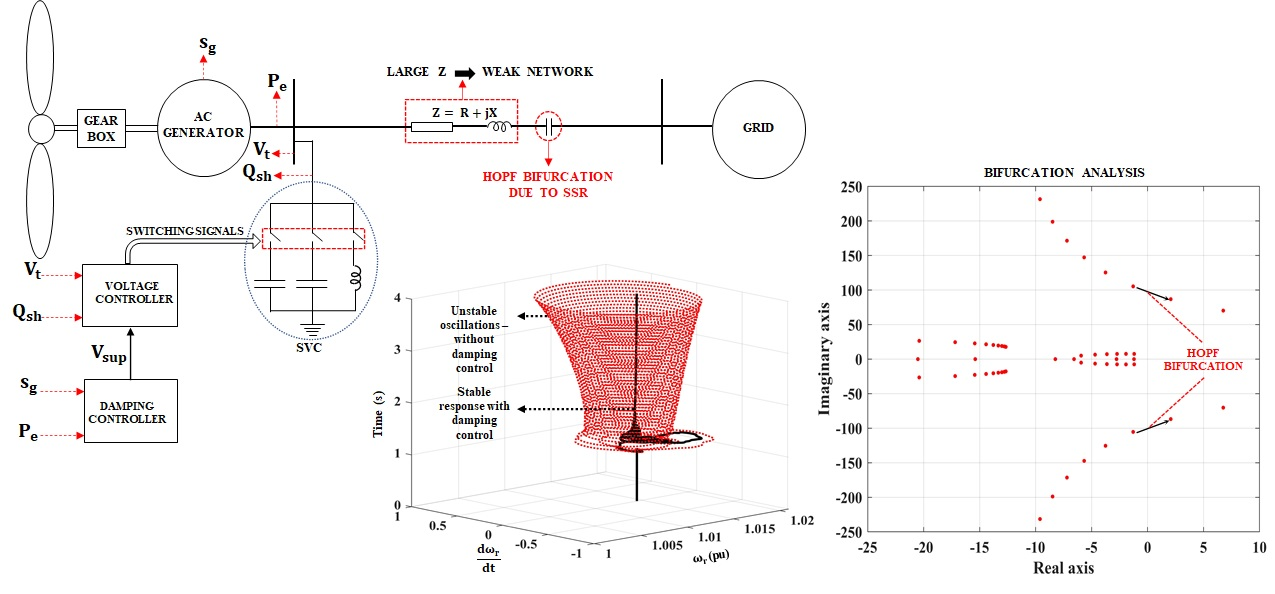
  • Proposing a new voltage regulator design for the SVC to aid in damping SSR along with a design of a new damping controller.
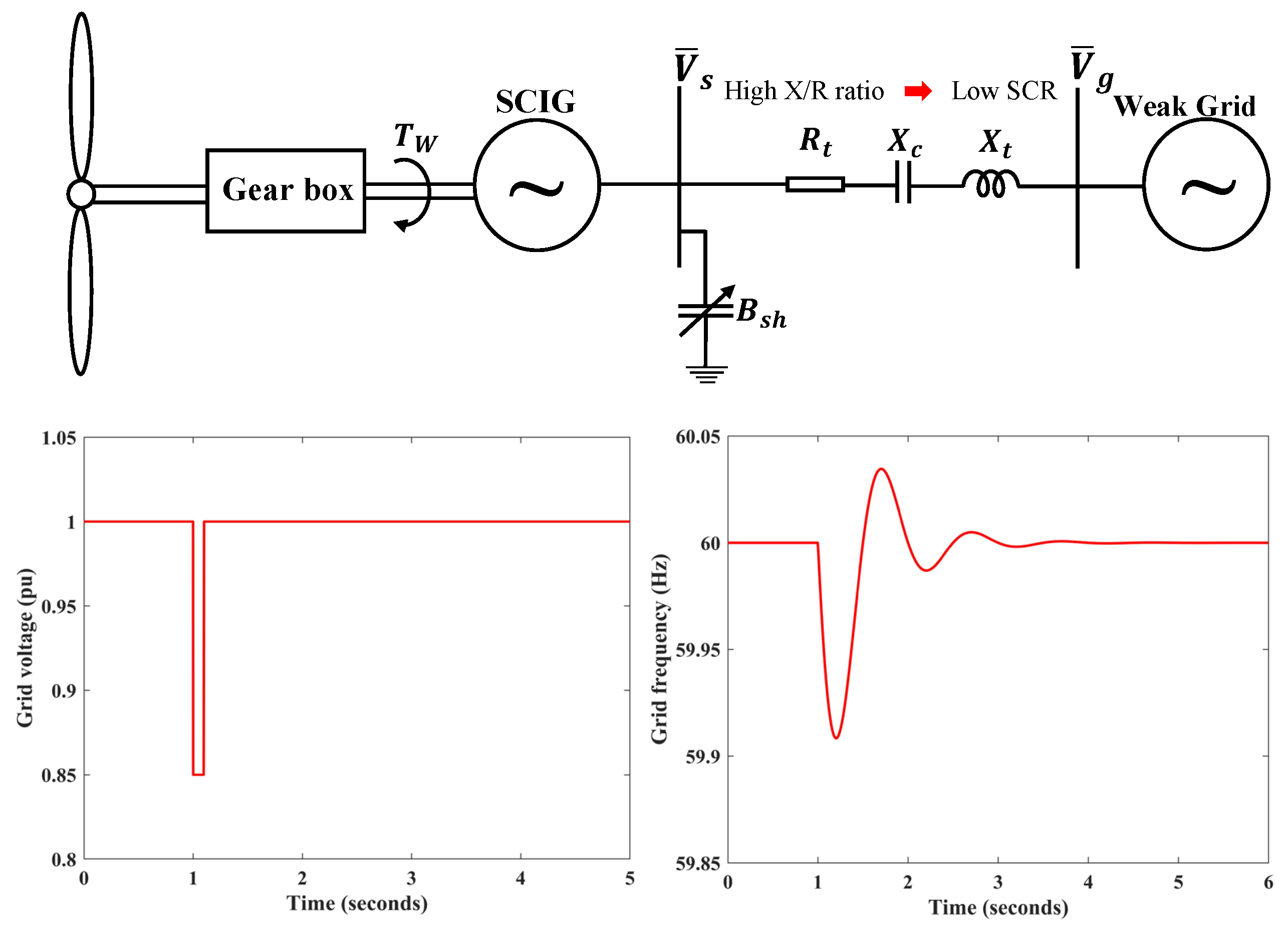
  • Validating the performance of the proposed controller through detailed time domain simulations when the system is subjected to frequency disturbances on the grid side, mimicking the action of speed governors, which has not been documented in the earlier research.

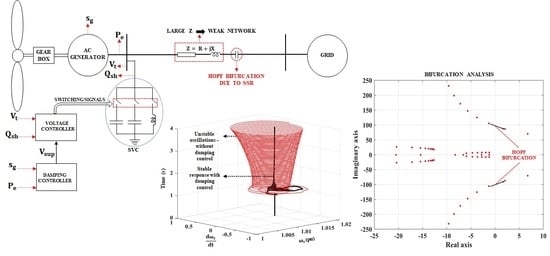
2. Dynamic Modeling of WT-SCIG and Controller

The single line diagram of the WT-SCIG system considered in this study is shown in Figure 1. The mathematical model of the induction generator and the network was developed based on [12] and is presented below. Following this, the mathematical models of the voltage regulator and the subsynchronous damping controller (SSDC) are presented.

2.1. Dynamics of Induction Generator

The detailed dynamic model of the SCIG is presented in this section. The dynamics of the stator and rotor windings are described by the following equations:
1 ω s X s 0 X m 0 0 X s 0 X m X m 0 X r 0 0 X m 0 X r d d t I d s I q s I d r I q r = V d s V q s 0 0 + R s X s 0 X m X s R s X m 0 0 s g X m R r s g X r s g X m 0 s g X r R r I d s I q s I d r I q r
where X s = X l s + X m , X r = X l r + X m , s g is the slip of the induction generator, which is given by s g = 1 ω r , and ω s is the synchronous speed in rad/s. The electromechanical dynamics of the wind turbine are described by the swing equation given as the following:
2 H g d s g d t = T e T w
where T e = X m ( I q s I d r I d s I q r ) is the electrical torque output of the wind turbine, T w is the torque input from the wind and H g is the inertia constant of the wind turbine in seconds. It is to be noted that Equations (1) and (2) are nonlinear.

2.2. Dynamics of Transmission Line, Shunt and Series Capacitors

The dynamics of the series capacitor compensated transmission line connecting the terminals of the SCIG to the grid is given by the following equation:
1 ω s X t 0 0 X t d d t I d I q = R t X t X t R t I d I q V d c V q c V d g V q g + V d s V q s
Shunt capacitors are installed at the terminals of the SCIG to supply the necessary reactive power to maintain the terminal voltage of the generator at an acceptable level. Equation (4) determines the dynamics of voltage across the shunt capacitor. Depending on whether the shunt compensation is fixed or variable, the susceptance of the shunt capacitor B s h = 1 / X s h is constant or is the output of the voltage regulator of the SVC, which is described in more detail in Section 2.3.
1 ω s d d t V d s V q s = 0 1 1 0 V d s V q s + X s h { I d s I q s I d I q }
Voltage across the series capacitor is described by the following differential equation:
1 ω s d d t V d c V q c = 0 1 1 0 V d c V q c + X c I d I q

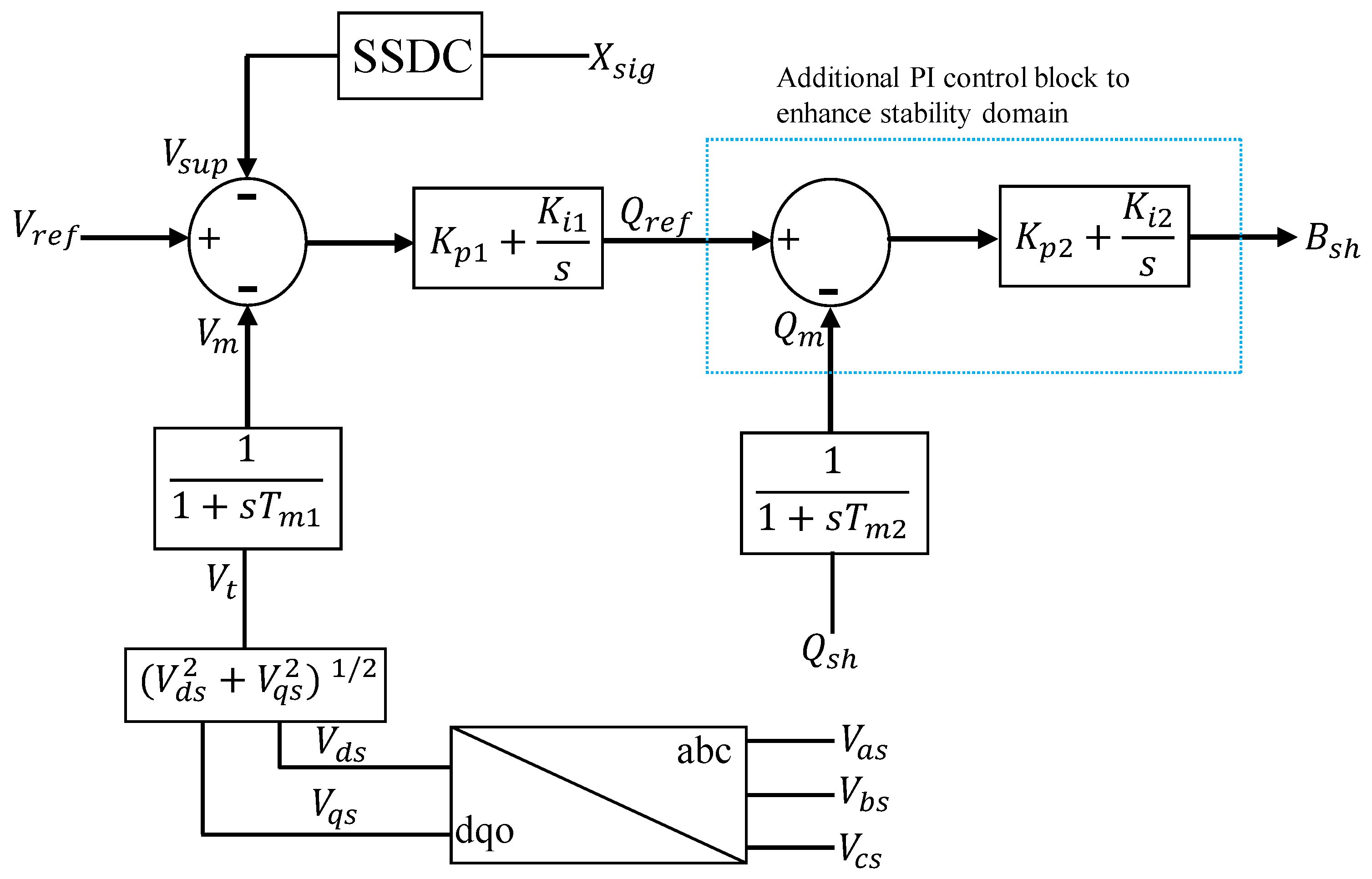
2.3. Design of Voltage Regulator

The block diagram of the voltage regulator for the SVC is given in Figure 2. The terminal voltage of the generator is sensed through a transducer, which has a time constant of T m 1 seconds and is compared with the reference voltage. The voltage error is processed by a PI controller, having proportional and integral gains K p 1 and K i 1 , respectively. The output of the PI controller gives the reactive power reference ( Q r e f ) for the shunt capacitor. This is compared with the actual value of the reactive power injected by the shunt capacitor ( Q s h = V m 2 B s h ) at the generator terminals, which is measured by a transducer with time constant T m 2 seconds. The reactive power error is processed by a second PI controller with proportional and integral gains K p 2 and K i 2 , respectively. The output of the second PI controller gives the susceptance B s h of the SVC. The proportional gain of the second PI controller enhances the stability domain (up to 95 % series compensation) of the system with measurement transducers with higher values of time constants, which is shown in Section 3.3.3. The presence of a second PI controller is helpful in tuning the response of the system if there are limits imposed on the gains of the first PI controller. There is an additional signal V s u p , which is a supplementary signal added to the first summing junction of the voltage regulator, which is used to control critical bifurcations in the system due to SSR. This is explained in more detail in the following section. The dynamics of the measurement blocks of the voltage regulator are described by the following equations:
T 1 d V m d t = V m + V t
T 2 d Q m d t = Q m + Q s h
Equations (8)–(11) define the dynamics of the two PI controllers.
d W 1 d t = K i 1 ( V r e f V m V s u p )
Q r e f = K p 1 ( V r e f V m V s u p ) + W 1
d W 2 d t = K i 2 ( Q r e f Q m )
B s h = K p 2 ( Q r e f Q m ) + W 2

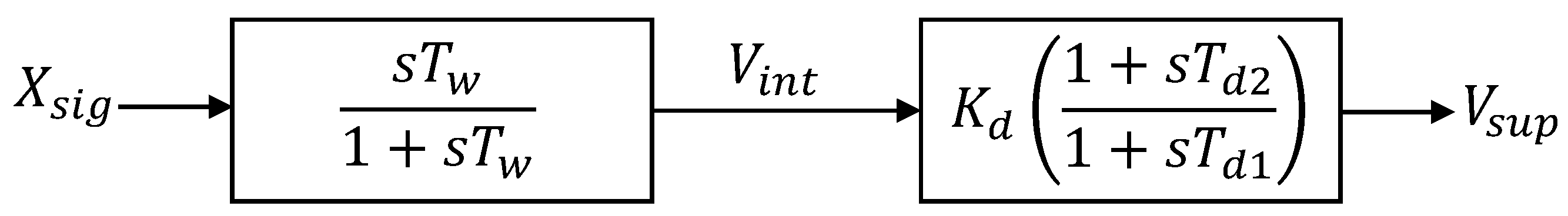
2.4. Design of the SSDC

The design of the subsynchronous damping controller (SSDC) consists of a washout block in series with a compensator, which provides a phase lead. The structure of the SSDC is very similar to that of a power system stabilizer used in synchronous generators to eliminate negative damping introduced by high gain exciters [13,14]. The signals X s i g in Figure 3 considered in this paper are the generator slip ( s g ) and the real power at the generator terminals ( P e ). The dynamics of the SSDC are given by the following equations:
T w ( d X s i g d t d V i n t d t ) = X s i g
T d 1 d V s u p d t K d T d 2 d V i n t d t = K d V i n t V s u p

3. Results

Eigenvalue analysis and time domain simulations were performed on the system under study and the results are presented in the sections that follow. The parameters of the induction generator, network and wind turbine can be found in Appendix A.

3.1. Stability Domain Analysis of WT-SCIG with Fixed Shunt Capacitor Compensation

Bifurcations are identified in the system under study by computing the eigenvalues of the linearized mathematical model. The critical bifurcations encountered in this study are the Hopf bifurcation and the saddle-focus [15] bifurcation, which result in a change in the stability of the equilibrium point. In addition to this, node-focus bifurcations were also observed in the power system, which may or may not cause a change in the stability of the equilibrium point and is, therefore, non-critical [16]. Stability domain of the system with respect to series compensation is defined by the Hopf bifurcation point at which SSR occurs.

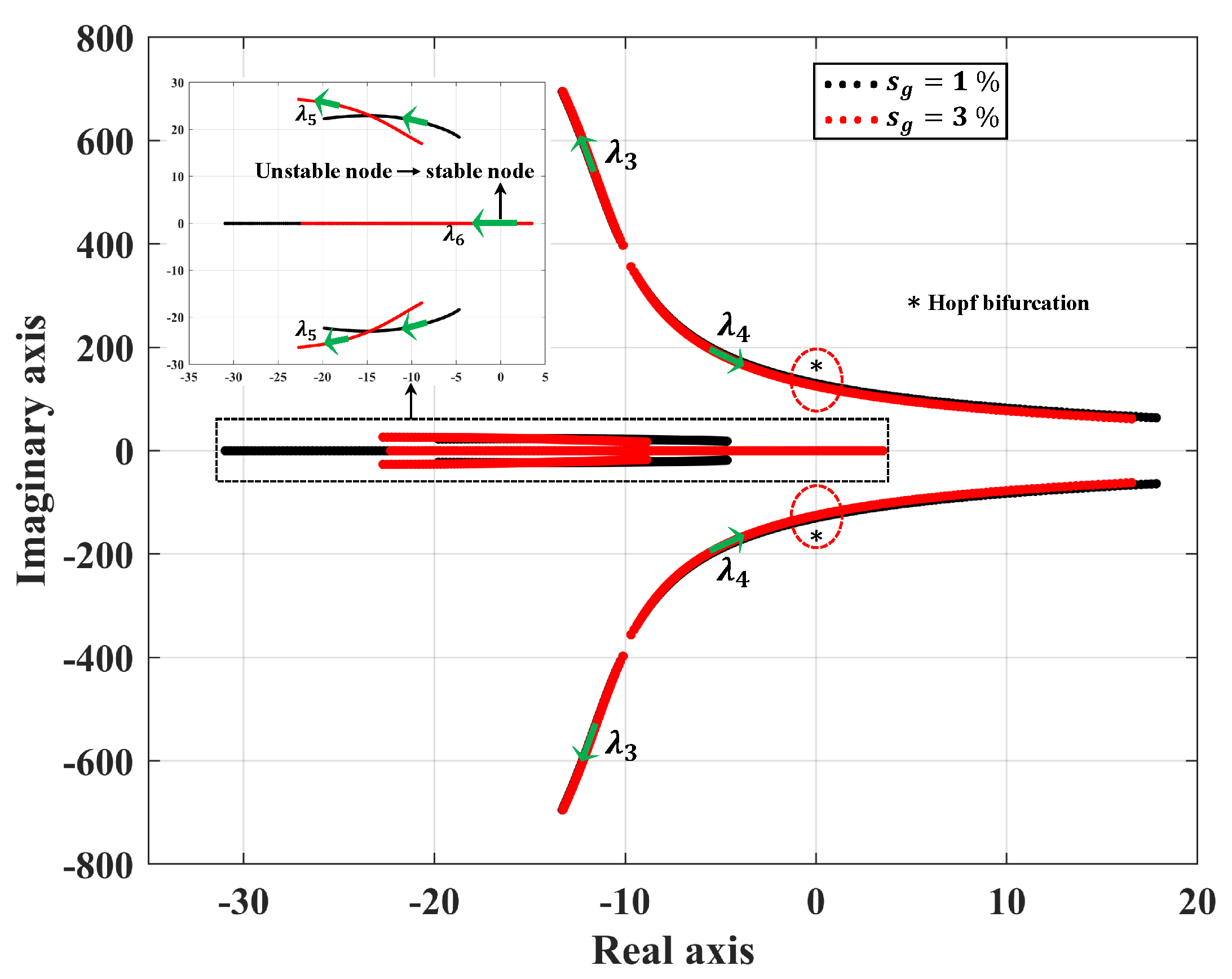
3.1.1. Eigenvalue Trajectories for Different Generator Slips

Bifurcations in the system with fixed shunt capacitor compensation at the SCIG terminals are analyzed, considering the degree of series compensation K c = X c / X t as the bifurcation parameter. Eigenvalues of the system with an X / R ratio of 30 are calculated and plotted on the complex plane when K c is varied from 0.005 to 0.98 for two different generator slips s g = 1 % and s g = 3 % , which correspond to low and high value wind speeds, respectively, as shown in Figure 4. The variations in torque input from the wind are assumed to be slow and hence are neglected in this analysis ( Δ T w 0 ). This greatly simplifies the computations, as the operating slip s g does not have to be calculated for each level of series compensation. Eigenvalues are presented for the system for 60 % series compensation in Table 1 for a slip of 1 % . It can be observed from the table that the system consists of 5 pairs of complex conjugate eigenvalues and 1 real eigenvalue. Among the complex conjugate eigenvalues, there are 3 pairs, which have frequencies above 60 Hz (Supersynchronous modes λ 1 , λ 2 , λ 3 ), and 2 pairs have frequencies below 60 Hz (Subsynchronous modes λ 4 , λ 5 ). The complex eigenvalues corresponding to λ 4 has a positive real part resulting in an unstable system making it the critical eigenvalue pair. The participation factors of the critical eigenvalue pair are presented in Table 2.
It was observed from the eigenvalue analysis that the supersynchronous modes are stable for the entire range of series compensation considered for s g of 1 % and 3 % . However, the damping of the subsynchronous mode decreases as K c increases, and when K c is between 0.575 and 0.58 , a Hopf bifurcation occurs due to SSR when s g is 1 % . However, at a higher slip s g of 3 % , the system is unstable for K c = 0.005 due to the presence of a real eigenvalue on the right half of the complex plane, resulting in the system being unstable. The equilibrium is called a ‘saddle-focus’, characterized by three leading eigenvalues given by λ 1 , 2 = 8.8894 ± j 16.957 and λ 3 = 3.5009 . The participation factors for these leading eigenvalues are presented in Table 3.
As the compensation increases, the unstable eigenvalue moves to the left half of the complex plane, and when K c > 0.315 , λ 3 mode crosses over from the right half to the left half of the complex plane, resulting in a bifurcation, making the system stable. The system remains stable as the percentage series compensation ( % K c = K c × 100 % ) increases to 60 % ( K c = 0.60 ) beyond which a Hopf bifurcation results, making the system unstable due to SSR. The critical percentage series compensation at which instability due to Hopf bifurcation is observed is slightly larger for a higher operating slip of the induction generator.

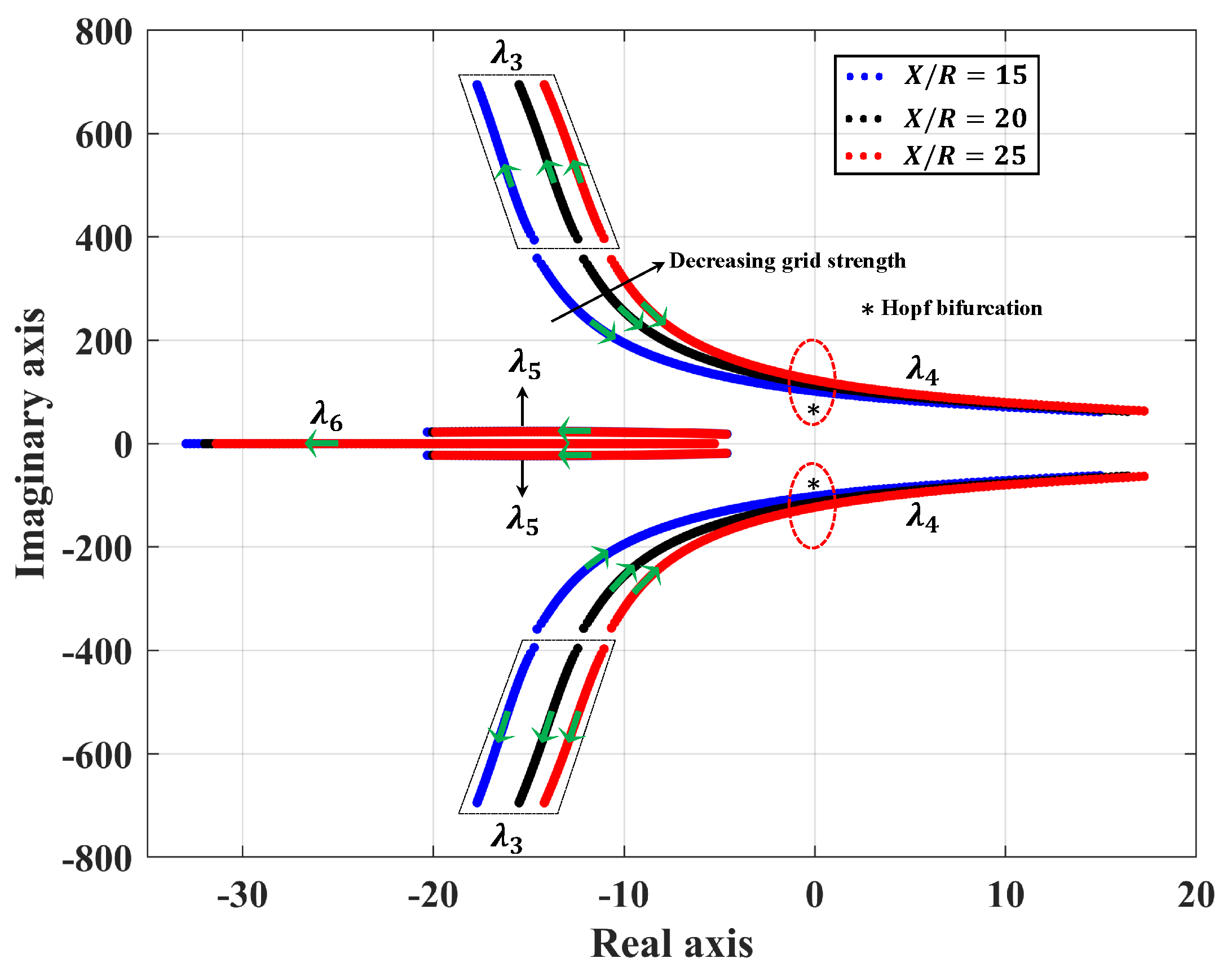
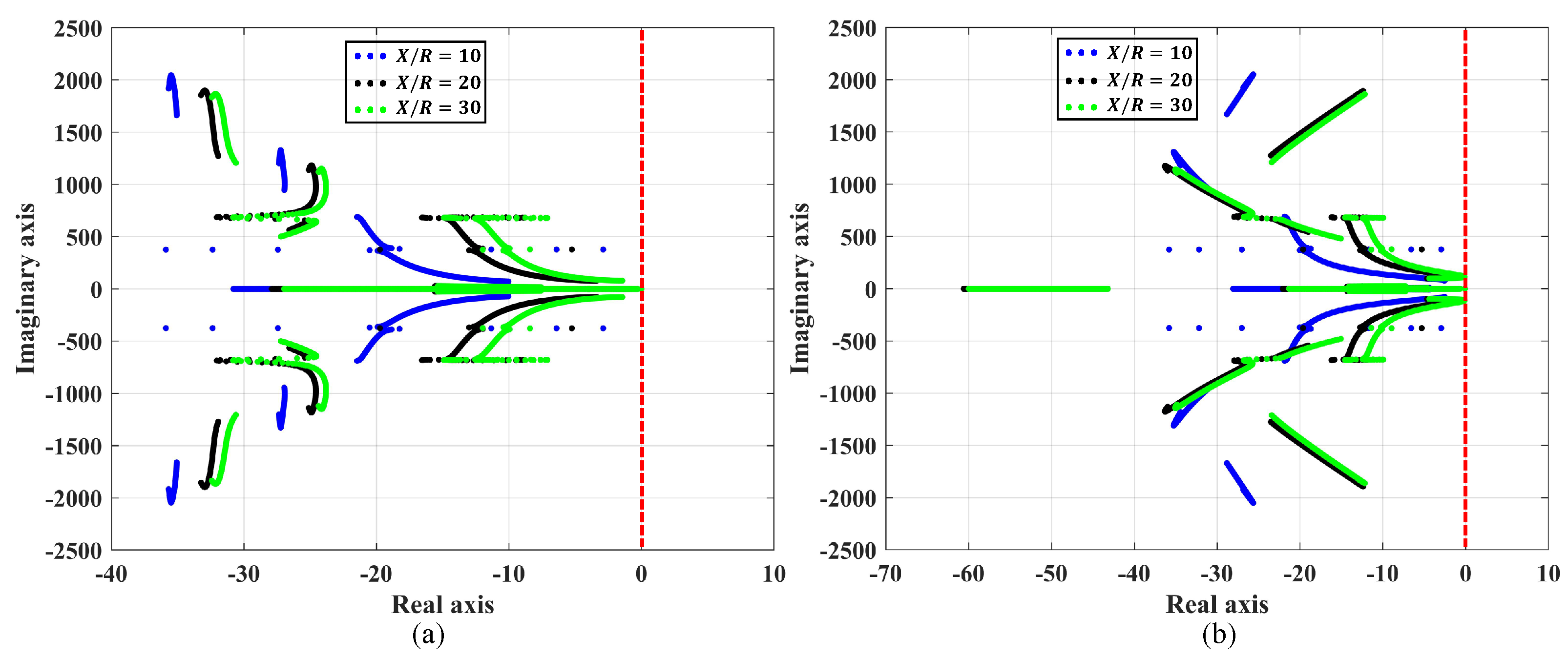
3.1.2. Eigenvalue Trajectories for Different Grid Strengths

Increasing the X / R ratio of the line decreases the Short Circuit Ratio (SCR) at the point of interconnection (POI), as the Thevenin impedance of the system up to the POI increases as the reactance of the line increases. This results in a weak interconnection to the grid. The eigenvalues of the system for a generator slip of 1 % are calculated for X / R ratios of 15, 20 and 25 and are plotted in Figure 5. Supersynchronous modes are stable for the entire range of series compensation considered but the subsynchronous mode becomes less damped as the degree of series compensation is increased. The non-oscillatory mode is stable for the entire range of compensation. SSR occurs as the percentage series compensation approaches 71.8 % , 65.6 % and 61.2 % for X / R ratios of 15, 20 and 25, respectively, which shows that as the grid becomes weaker, there is a higher possibility of SSR at lower values of series compensation. This is further evident in Figure 6, where the critical value of series compensation is plotted as a function of X / R ratio of the network, which gives the stability boundary with respect to series compensation.

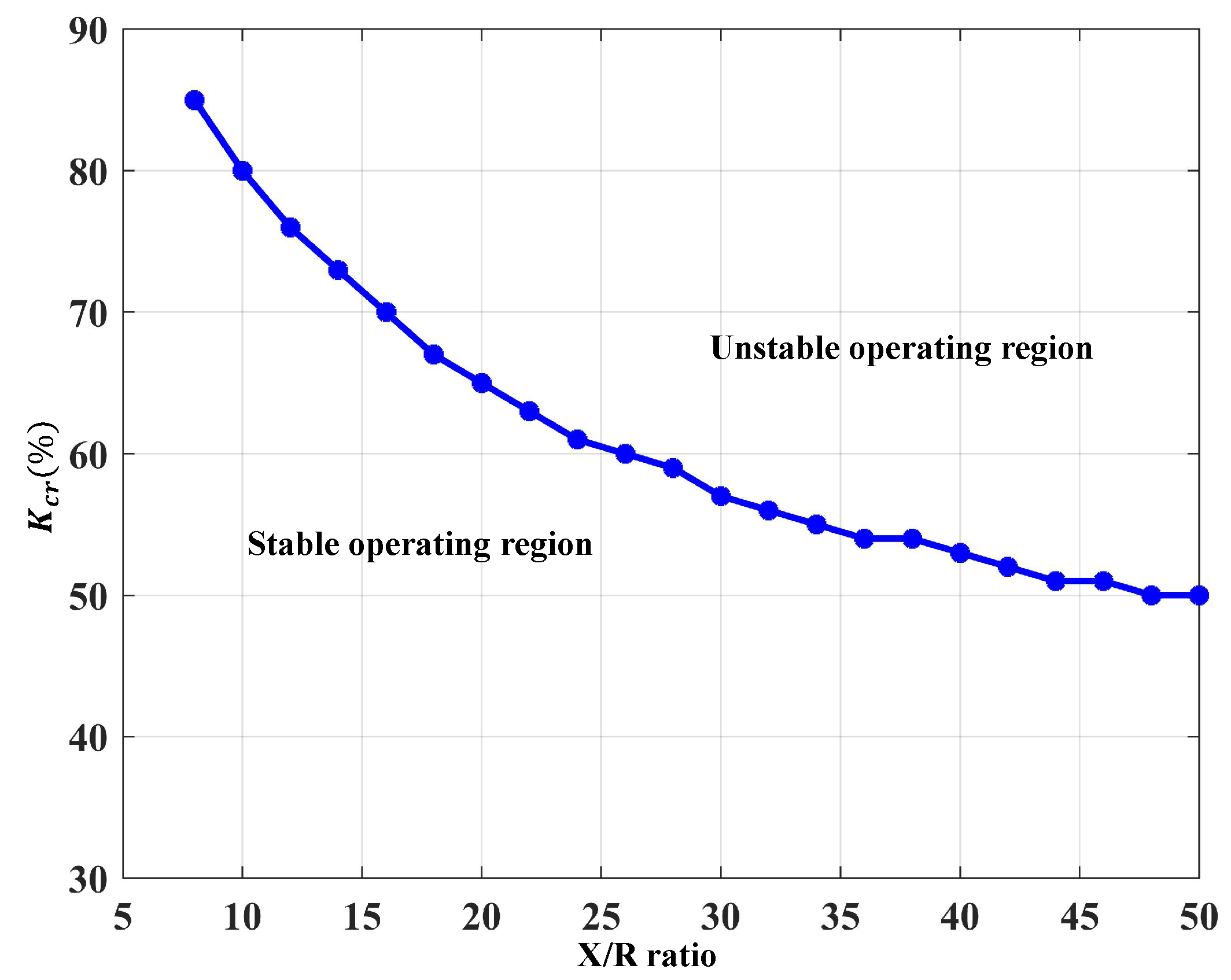
3.2. Stability Domain Analysis of WT-SCIG with SVC at the Stator Terminals

An SVC equipped with a voltage controller is used at the generator terminal in place of a fixed capacitor to supply the needed reactive power to maintain the voltage at the bus at V r e f . The voltage controller introduces 4 new states in the analysis: V m and Q m , which correspond to measured signals of terminal voltage and reactive power, and W 1 and W 2 , which correspond to the intermediate states of the PI controllers. The parameters of the SVC voltage regulator for this system under consideration (unless otherwise specified) are presented in Table 4.
Eigenvalues of the system are plotted on the complex plane as K c is varied from 0.001 to 0.95 for different operating conditions. It should be noted that the equilibrium point corresponding to the slip of the generator does not change as the series compensation is varied because the generator terminal voltage is held constant by the SVC.

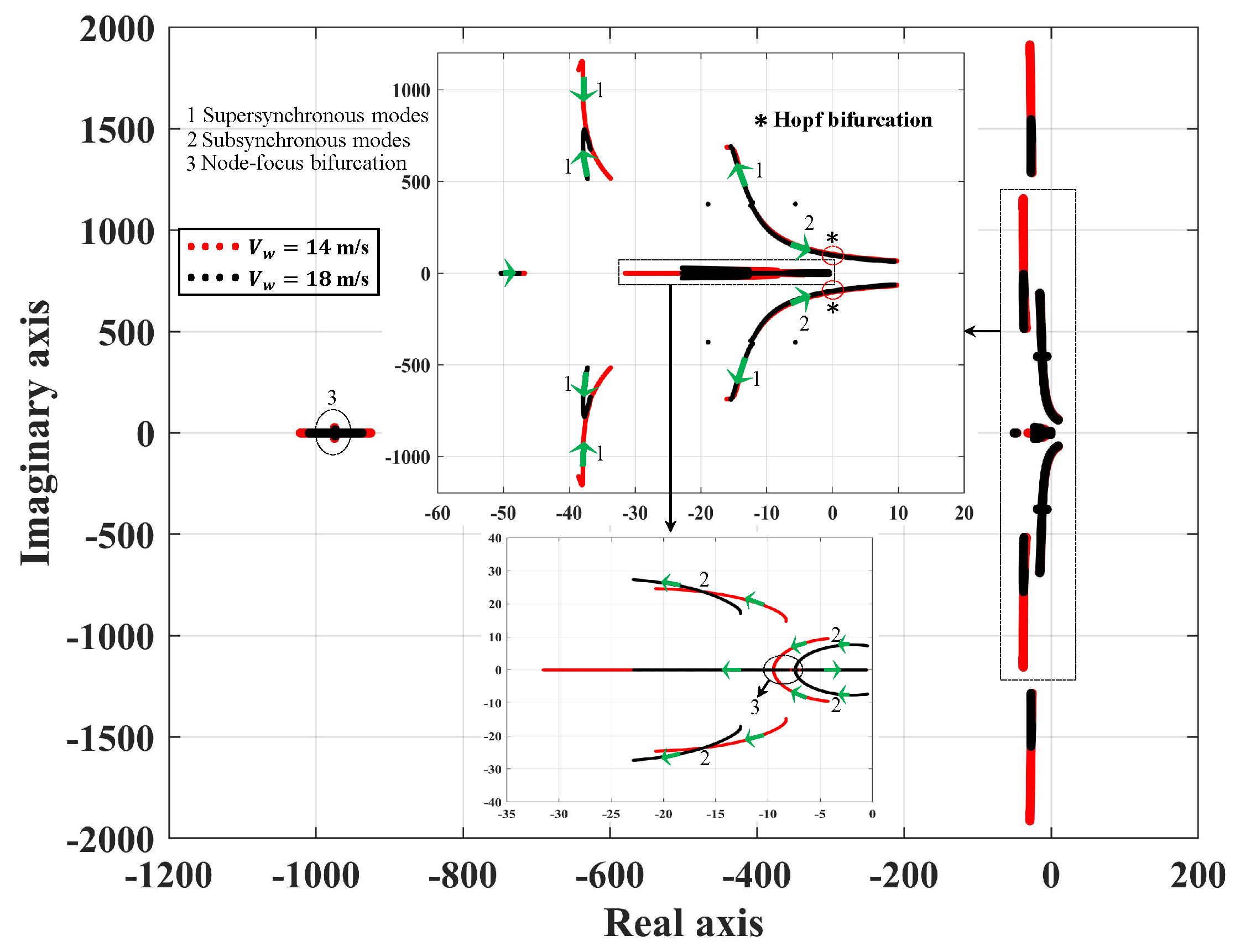
3.2.1. Eigenvalues for Low and High Wind Speeds

Eigenvalues of the system with an SVC at the generator terminal are plotted in Figure 7 for wind speeds of 14 and 18 m/s. When the wind speed is 18 m/s, the operating slip of the SCIG is 3.051 % . For a small value of compensation K c = 0.001 , 7 complex conjugate pairs of eigenvalues and one real eigenvalue all on the left half of the complex plane are observed. Among the complex conjugate pairs of eigenvalues, 4 of them are of low frequency: λ 1 = 974.04 ± j 14.893 , λ 2 = 12.633 ± j 17.108 , λ 3 = 0.4911 ± j 7.3045 and λ 4 = 18.911 ± j 376.28 , which follow different pathways on the complex plane as K c is varied. As the series compensation is increased, λ 1 starts moving toward the right half of the complex plane, and its frequency of oscillation decreases as well. When K c changes from 0.074 to 0.075 , a node-focus bifurcation results from λ 1 splitting into 2 real eigenvalues: λ 11 = 975.15 , λ 12 = 972.57 , which then move in opposite directions as K c is increased. However, these eigenvalues remain in the left half of the complex plane as K c is increased to 0.95 . As K c changes from 0.697 to 0.698 , a second node-focus bifurcation takes place where λ 3 = 7.3577 ± j 0.51245 transforms into 2 real eigenvalues: λ 31 = 7.6109 , λ 32 = 7.136 , and move in opposite directions. An increase in K c also causes λ 4 to move toward the right half of the complex plane; a Hopf bifurcation occurs in the system when K c changes from 0.742 to 0.743 as λ 4 , which is now 0.0118 ± j 97.353 , changes to 0.02075 ± j 97.166 , and the system becomes unstable due to SSR.
When the eigenvalues of the system for lower wind speed of 14 m/s are analyzed, 6 complex conjugate eigenvalue pairs (stable foci) and 3 stable nodes are observed. Among the 6 complex conjugate pairs, 3 are low frequency modes: λ 1 = 4.2745 ± j 9.4714 , λ 2 = 8.2775 ± j 14.712 and λ 3 = 18.917 ± j 376.28 . The 3 stable nodes are λ 4 = 1021.3 , λ 5 = 925.66 and λ 6 = 46.858 . As K c is increased, λ 1 moves further into the left half of the complex plane and the frequency of oscillation decreases; at K c = 0.559 , λ 1 = 9.4476 ± j 0.52247 , which is a stable focus, changes into 2 stable nodes: λ 11 = 9.6715 and λ 12 = 9.2474 , which is the result of a node-focus bifurcation. Eigenvalue λ 2 moves further into the left half of the complex plane as K c increases. When K c changes from 0.703 to 0.704 , λ 3 = 0.0259 ± j 103.85 crosses over to the right half of the complex plane and changes to λ 2 = 0.0057 ± j 103.66 as a result of a Hopf bifurcation due to SSR. When K c increases, λ 4 and λ 5 move toward each other; when K c changes from 0.938 to 0.939 , λ 4 = 979.87 and λ 5 = 968.33 collide and transform into a pair of complex-conjugate eigenvalues λ 45 = 974.14 ± j 4.0936 as the result of a node-focus bifurcation. It should be noted that the system is already unstable, due to the earlier Hopf bifurcation. Additionally, λ 6 starts moving along the real axis toward the right as K c increases, but it still remains in the left half of the complex plane.

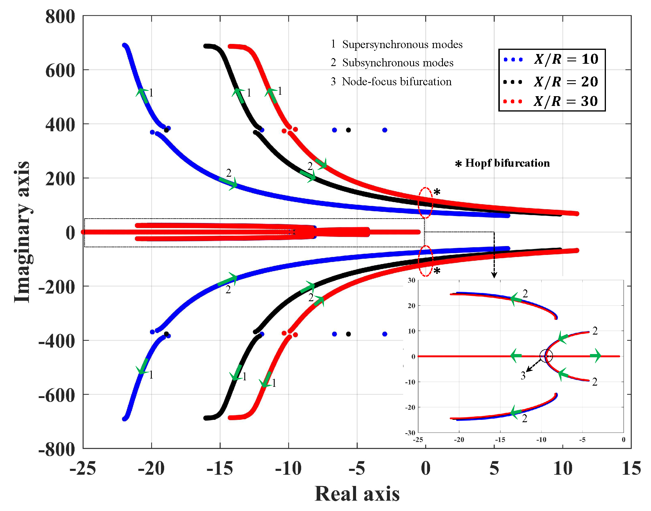
3.2.2. Eigenvalues for Different Grid Strengths

Eigenvalues are computed for various levels of series compensation for 3 different grid strengths, which are indicated by the X / R ratio of the line and are traced on the complex plane as given in Figure 8. The system is analyzed for a lower wind speed of 14 m/s because it is observed from the previous section that subsynchronous oscillations occur at low values of K c when the power generated is low. The system with X / R = 10 has a node-focus bifurcation as K c changes from 0.563 to 0.564 as the stable focus λ = 9.5344 ± j 0.4132 transforms into 2 stable nodes each moving in the opposite direction as K c is increased. When K c changes from 0.857 to 0.858 , the complex conjugate eigenvalue pair λ c r = 0.0528 ± j 73.976 crosses over to the right half of the complex plane and becomes λ c r = 0.0069 ± j 73.81 as a result of a Hopf bifurcation, which gives rise to unstable oscillations at a subsynchronous frequency.
Similar behavior is encountered in the system for higher X / R ratios but at lower values of K c . The node-focus bifurcation occurs when K c changes from 0.558 to 0.559 and from 0.557 to 0.558 for X / R ratios of 20 and 30, respectively. The system undergoes a Hopf bifurcation when K c is close to 0.704 and 0.623 with λ c r = 0.0057 ± j 103.66 and λ c r = 0.0085 ± j 120.02 for X / R ratios of 20 and 30, respectively. This shows that as the strength of the grid decreases, the percentage series compensation at which a Hopf bifurcation occurs becomes smaller, making it crucial to implement a damping controller in order to avoid this phenomenon. The stability boundary with respect to series compensation and the X / R ratio of the network is shown in Figure 9, which confirms that the stability domain with respect to series compensation becomes smaller for weaker networks. However, the system with SVC has a slightly larger stability domain, compared to the system with fixed shunt capacitors at the stator terminals of the SCIG.

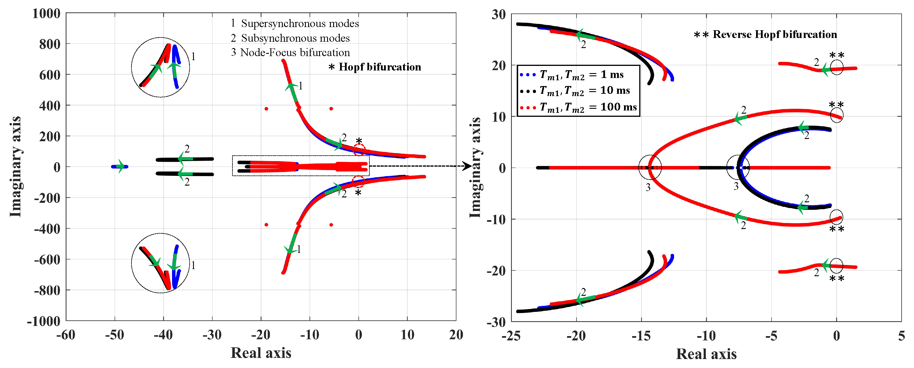
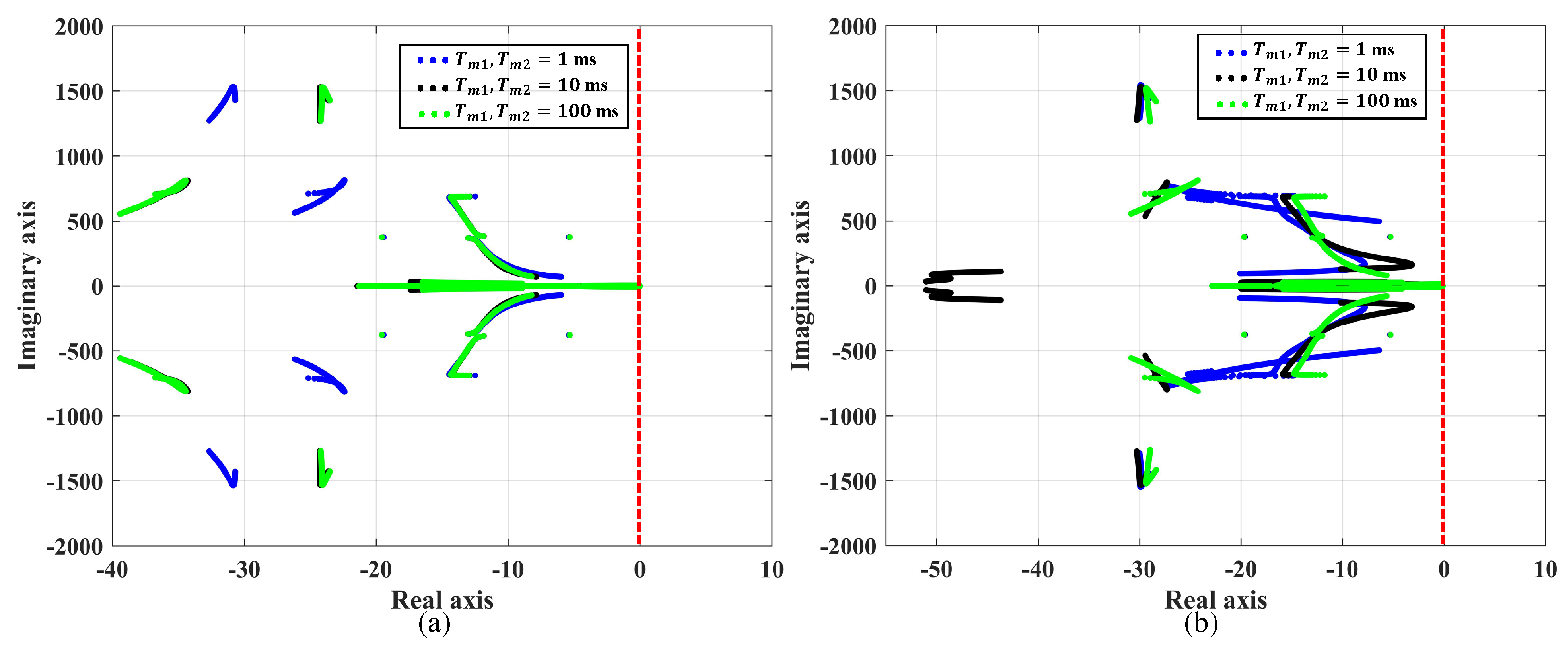
3.2.3. Eigenvalues for Different Measurement Time Delays

Time delays in measurement of voltage magnitude and reactive power are modeled using a first order transfer function. Eigenvalues of the system are traced when K c is varied from 0.001 to 0.95 and are plotted on the complex plane for 3 different measurement time delays in the voltage regulator which can be found in Figure 10. The system is analyzed for higher wind speed V w = 18 m/s because certain unique bifurcations occur in this system at this wind speed. When the measurement time delay is 1 ms, the system undergoes a node-focus bifurcation at K c = 0.075 and K c = 0.704 and a Hopf bifurcation due to SSR at K c = 0.743 . With a measurement delay of 10 ms, the system undergoes a Hopf bifurcation at K c = 0.679 and a node-focus bifurcation at K c = 0.691 as a stable focus transforms into 2 stable nodes but the system is already unstable at K c = 0.679 .
As the measurement time delay is increased to 100 ms, for K c = 0.001 , there are 2 pairs of complex conjugate eigenvalues λ 1 = 1.4651 ± j 19.368 and λ 2 = 0.2911 ± j 9.7375 on the right half of the complex plane, which results in the system being unstable. When K c increases, these two pairs move toward the left half of the complex plane and when K c = 0.038 , λ 1 = 1.1153 ± j 19.34 and λ 2 = 0.0075 ± j 10.014 . Though the real part of λ 2 is negative, the system still is unstable, as λ 1 has a positive real part. When K c approaches 0.172 , λ 1 changes to 0.0068 ± j 19.208 , which means all the eigenvalues of the system have negative real parts, indicating a stable system. Since the system changes from an unstable state to a stable state because of the movement of a complex conjugate pair of eigenvalues to the left half of the complex plane from the right, the system undergoes a reverse Hopf bifurcation.
The reason for this phenomenon can be explained as follows: the system is unstable for small values of series compensation, due to increased time delays in measurement. When the series compensation is increased, the system becomes more and more stable because increasing the series capacitive reactance decreases the effective line reactance, which decreases the time constant of the electrical circuit, thus compensating for measurement delays. Hence, the system can be stabilized by increasing the series compensation above a certain threshold when instability due to large measurement delays is experienced. The upper limit of K c is determined by the Hopf bifurcation, which occurs due to SSR at K c = 0.683 where λ c r = 0.0223 ± j 108.57 . Finally, a node-focus bifurcation takes place at K c = 0.865 , where a stable focus changes into 2 stable nodes but the system is already unstable due to SSR.

3.3. Stability Domain Analysis of WT-SCIG with SVC and SSDC

In this section, the performance of the designed damping controllers based on slip signal (SSDC-A) and real power (SSDC-B) is analyzed through computing eigenvalue trajectories as K c is varied from 0.001 to 0.95 for various X / R ratios, wind speeds and measurement time delays. The controller gains of the SVC and SSDC are tuned for the various scenarios considered to obtain a stable system characterized by all eigenvalues on the left half of the complex plane up to a series compensation of 95 % . The parameters of the network and wind speeds are the same as those considered in Section 3.2.

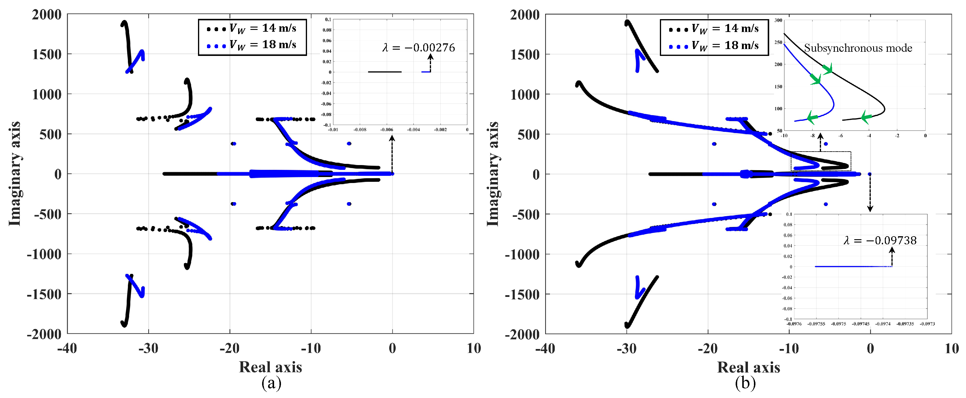
3.3.1. Eigenvalue Trajectories with SSDC for Low and High Wind Speeds

Eigenvalue trajectories of the system for an X / R ratio of 20 with SSDC-A are computed for wind speeds V w of 14 and 18 m/s and are presented in Figure 11 on the left. The subsynchronous mode starts moving toward the right half of the complex plane but even for a compensation of K c = 0.95 , the corresponding eigenvalue pairs are λ s u b = 3.2013 ± j 79.178 and λ s u b = 8.2223 ± j 72.016 for wind speeds of 14 and 18 m/s, respectively, which have negative real parts. The eigenvalue closest to the imaginary axis is λ = 0.00276 , which corresponds to V w = 18 m/s.
Similarly, for the system with SSDC-B, eigenvalue trajectories are computed for wind speeds of 14 and 18 m/s and are plotted in Figure 11 to the right. It is observed that the damping of the subsynchronous mode starts reducing as the amount of series compensation K c is increased from 0.001 up to 0.793 ; beyond that, the damping starts increasing as the compensation is increased. A similar phenomenon is observed for V w = 18 m/s, except that the damping of the subsynchronous mode decreases for K c up to 0.725 ; beyond this, the damping increases. However, all the eigenvalues of the system for both low and high wind speeds lie on the left half of the complex plane, which shows that the Hopf bifurcation is eliminated for the entire range of series compensation considered. The parameters of the SVC voltage regulator and SSDC-A and B are listed in Table 5.

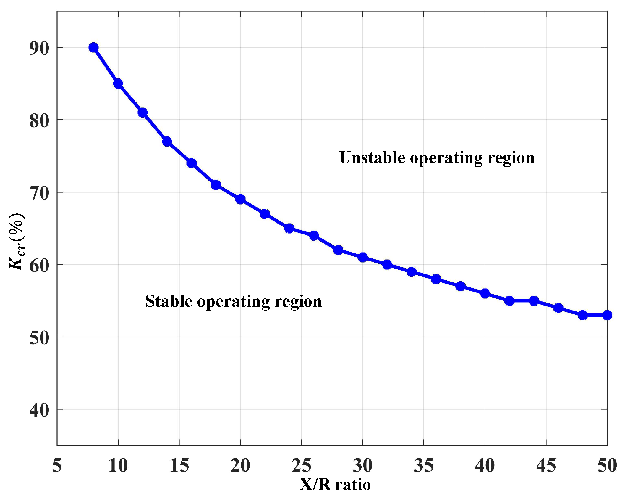
3.3.2. Eigenvalue Trajectories with SSDC for Varying Grid Strengths

Eigenvalues of the system with SSDC-A and SSDC-B are traced on the complex plane for varying grid strengths, which is a function of the X / R ratio. It was shown in Section 3.2.2 that as the strength of the grid decreases, the percentage series compensation at which the system becomes unstable due to SSR becomes smaller. In Figure 12, it is shown that with SSDC-A and SSDC-B, the eigenvalues of the system are all found to lie on the left half of the complex plane, thus eliminating the Hopf bifurcation due to SSR. In SSDC-B, with controller gains K p 1 , K p 2 = 0.1 and K i 1 , K i 2 = 50 and a stabilizer gain K S S of 0.3 , all the modes are found to be well damped for X / R ratios to about 15. Beyond that, the stabilizer gain is increased to 0.7 and all the modes are found to be well damped for X / R = { 10 , 20 , 30 } , and those are shown in Figure 12b. The values of control gains of the SVC and SSDC are presented in Table 6. Re-tuning of the stabilizer and PI controllers in the voltage regulator are not needed with SSDC-A for all the X / R ratios considered here.

3.3.3. Eigenvalue Trajectories with SSDC for Varying Measurement Time Delays

Eigenvalues of the system with SSDC for 3 values of measurement delays (1, 10 and 100 ms) are plotted on the complex plane and are presented in Figure 13. The parameters of SSDC-A and -B and that of the SVC with SSDC-A are same as those presented in Table 5. For the system with SSDC-A, all the modes are damped and no re-tuning of the PI controls of the voltage controller is needed. However, with SSDC-B, the controller gains of the SVC have to be re-tuned in order to obtain a stable system up to 95 % series compensation for each of the time delays considered here; those values are presented in Table 7. Hence, it is shown that both SSDC-A and SSDC-B are able to mitigate subsynchronous oscillations as well as the unstable low frequency modes, which appear for a time delay of 100 ms in the system without the damping controller.

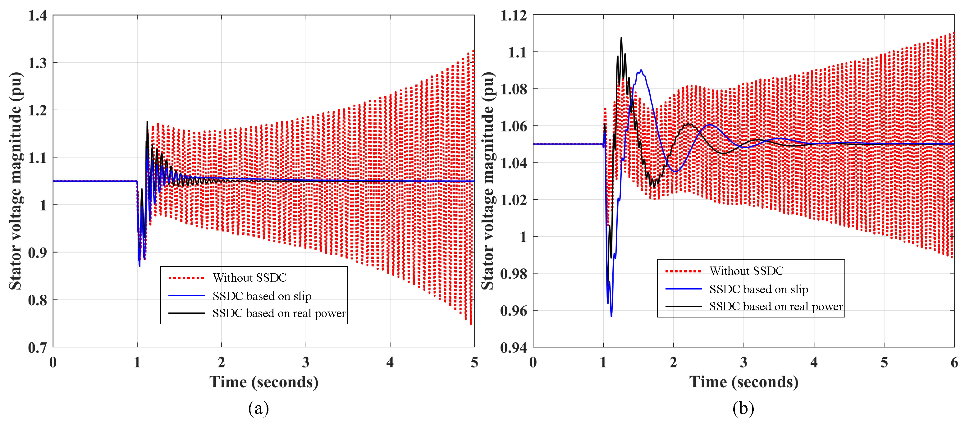
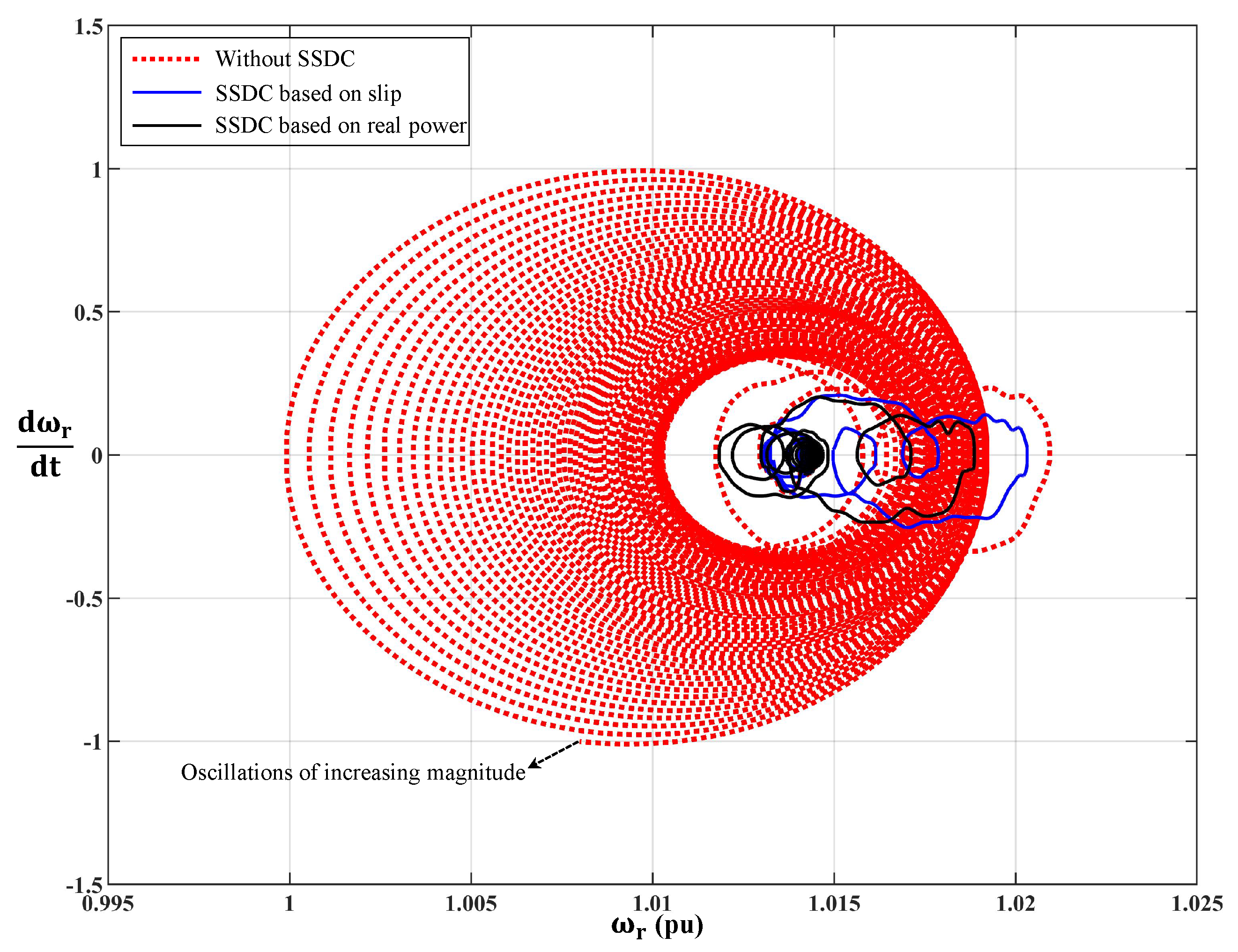
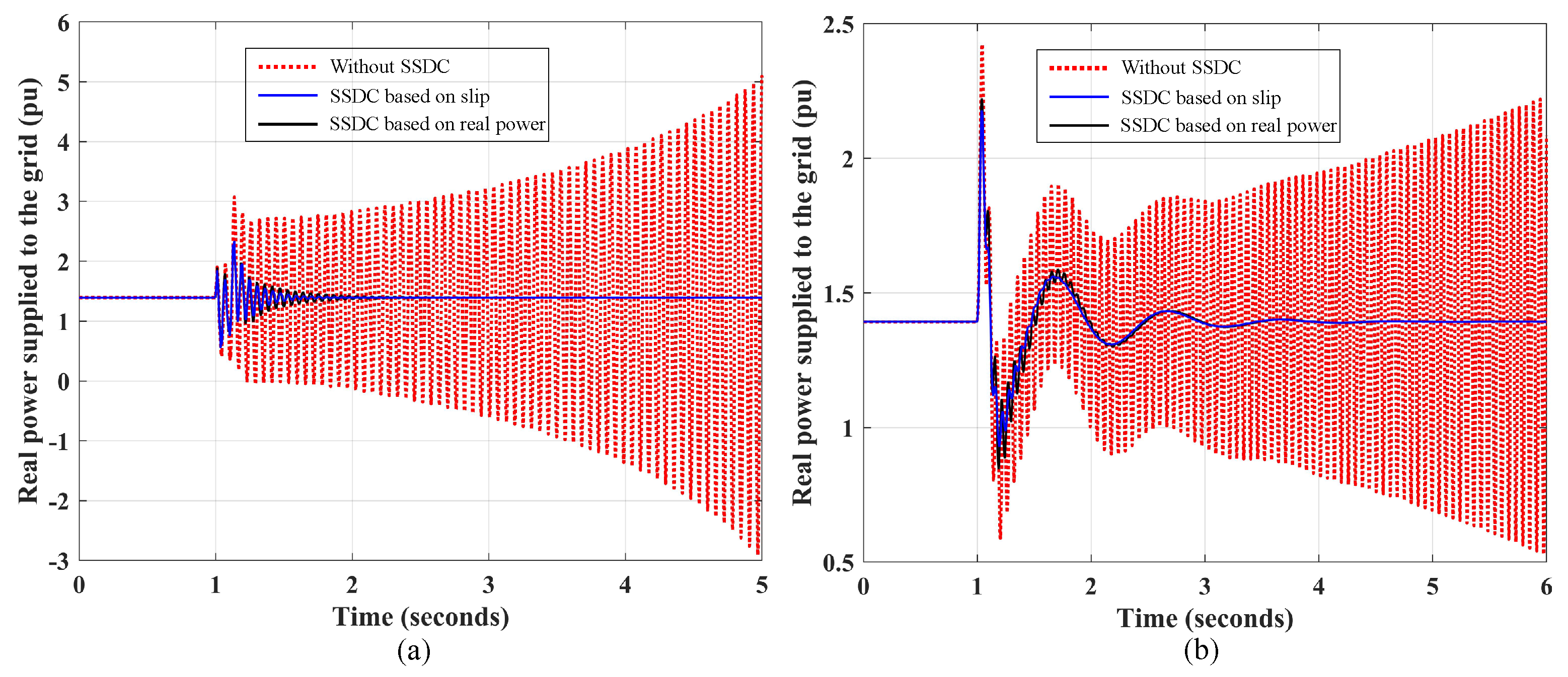
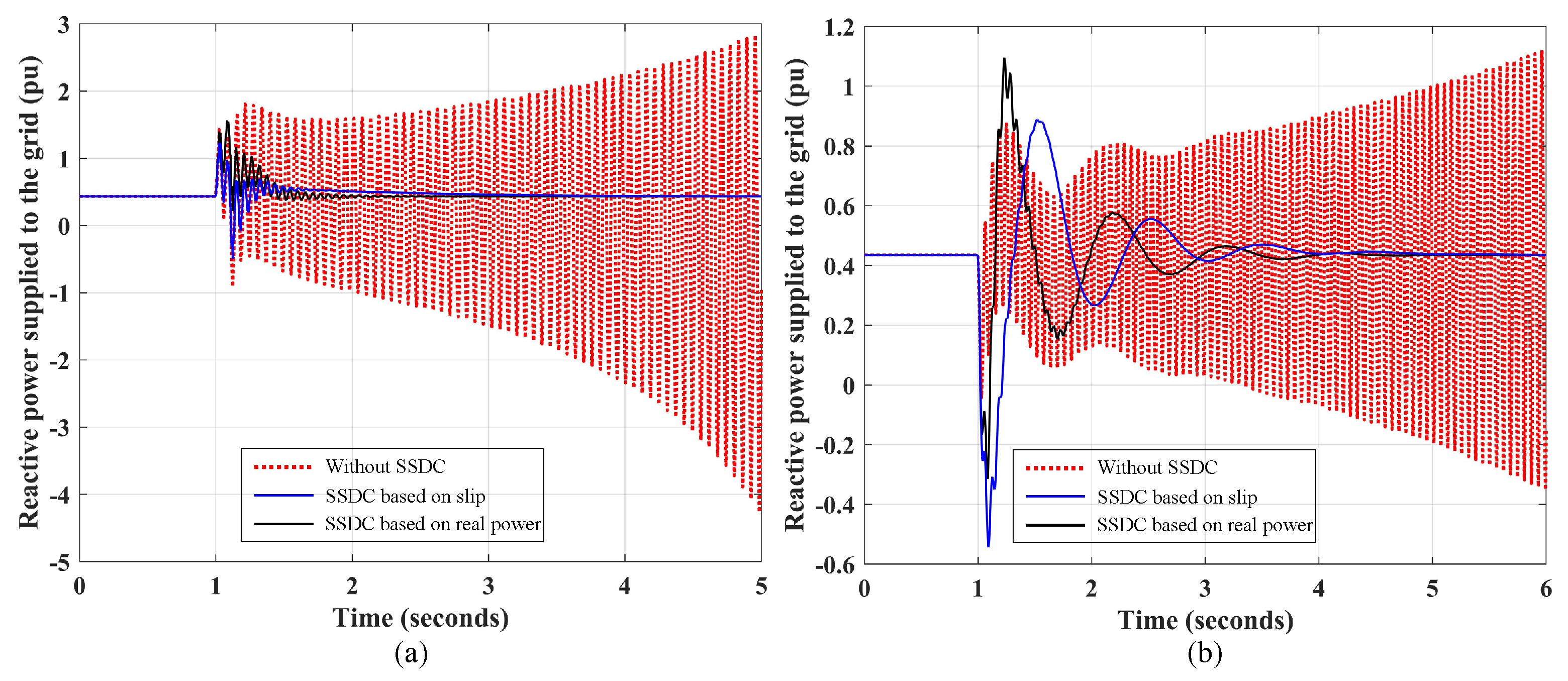
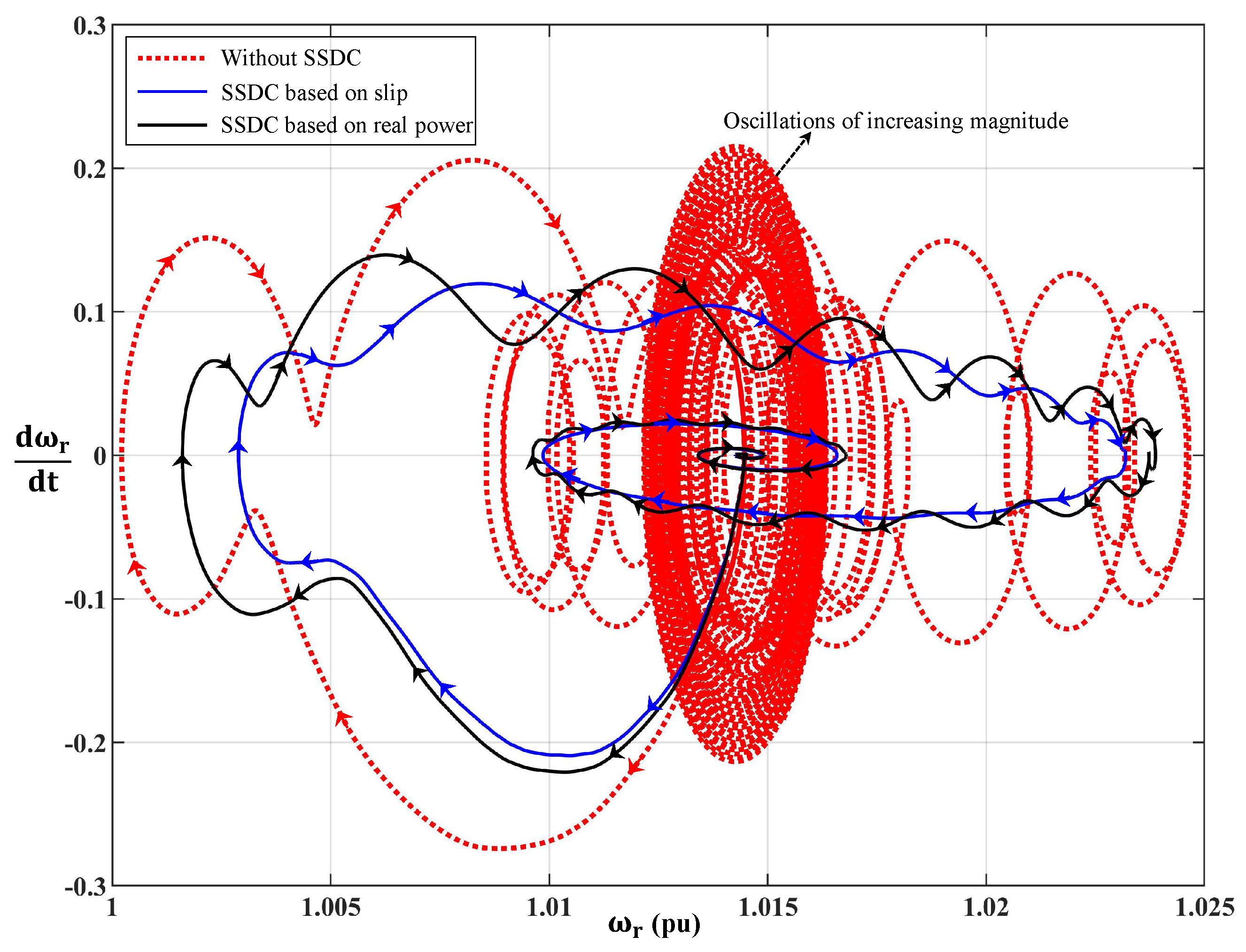
3.4. Time Domain Simulation Results

The detailed non-linear model of the system with and without the designed SSDC is simulated and the system variables are plotted. The disturbance applied in the system is a three-phase fault at 1 s on the grid side, which causes a temporary voltage reduction of 15 % . The fault is cleared in 6 cycles. In addition to this, a frequency disturbance is simulated using a mathematical function given by the following:
f ( t ) = f o e x p ( τ t ) sin ( ω n t )
where τ is the damping term and ω n is the frequency of the disturbance. Here, τ = 2.5 and ω n = 2 rad/s which is of the order of frequency involving electromechanical oscillations in the grid. This mimics the frequency changes in the grid due to the response of speed governors to disturbances in the grid. An X / R ratio of 20 is considered with a percentage series compensation of 71 % , which is slightly above the Hopf bifurcation point due to SSR in the system without SSDC at a wind speed of 14 m/s. Parameters of the SVC voltage regulator for the system without SSDC can be found in Table 4, whereas, for the system with SSDC, the parameters of the voltage regulator and SSDC are listed in Table 5.
The terminal voltage of the generator has growing oscillations due to SSR, which is seen in Figure 14. If unchecked, this will result in dangerous values of overvoltages, which is harmful to the system. With the SSDC, the oscillations are damped, which can be observed in Figure 14a,b.
The traces of real and reactive power delivered to the grid when the system is subject to disturbances are shown in Figure 15 and Figure 16, respectively. Without the SSDC, real power delivered to the grid starts oscillating between negative and positive values past 2 s (Figure 15a), implying that power flows back and forth between the SCIG and the grid. The same is observed in Figure 16 with the reactive power delivered to the grid. However, in Figure 15 and Figure 16, the oscillations due to SSR are damped by the proposed controllers.
Oscillations in the stator and rotor currents result in growing oscillations in the electrical torque produced, which causes a mismatch in the mechanical torque input from the wind and the electrical torque output of the generator, which is manifested as oscillations of increasing magnitude in the speed of the rotor. However, the system with SSDC returns to the same operating point after a few cycles, which is observed from the dynamic torque–speed characteristics shown in Figure 17 and Figure 18.

4. Conclusions

An SCIG-based wind turbine with fixed shunt capacitors at the stator terminals connected to the grid through a series compensated line becomes unstable because of a Hopf bifurcation due to SSR for both low and high wind speeds. The percentage series compensation at which the Hopf bifurcation occurs in the system is greater for higher wind speeds. This is because as the wind speed attains higher values, the magnitude of slip is higher, resulting in a less negative rotor resistance; hence, the system requires a higher percentage of series compensation to become unstable. There is a possibility of non-oscillatory instability for small values of percentage series compensation at higher wind speeds due to the presence of a saddle-focus equilibrium point, resulting in an unstable node. This makes the operation of the system impossible without a minimum level of series compensation when the wind speed is high. An SVC used in the place of a fixed capacitor is able to eliminate the unstable node at small values of series compensation at high wind speeds. In addition to a Hopf bifurcation, a node-focus bifurcation is also introduced into the system, which may not affect the stability of the system. In addition, the percentage series compensation at which SSR occurs is increased with the SVC. The Hopf bifurcation point, which defines the stability domain with respect to series compensation, is affected by the strength of the grid in systems with fixed capacitors as well as an SVC equipped with a voltage regulator. As the strength of the grid decreases with an increase in the X / R ratio, the stability domain with respect to the series compensation becomes smaller. This is due to the fact that as the X / R ratio of the line increases, for a given reactance, the resistance of the line becomes smaller. This causes the net resistance of the system to become negative due to the ‘Induction Generator Effect’ of SSR at lower values of percentage series compensation. However, the Hopf bifurcation point can be shifted in the system with SVC by proper adjustment of controller parameters in the voltage regulator. With higher time delays, there is a possibility of unstable low frequency oscillations, which are eliminated by higher levels of series compensation. Hence, stable operation of a system with higher measurement delays might not be possible without a minimum level of series compensation. A supplementary damping controller is needed for stable operation of the system for high levels of series compensation. A damping controller based on the generator slip signal as well as the real power at the terminals is able to successfully damp subsynchronous oscillations when tuned properly. This paper highlights new bifurcations in a WT-SCIG with a weak interconnection to the grid, considering a series compensated line, using a fixed capacitor and an SVC. The existence of a saddle-focus equilibrium point is shown in the system with fixed shunt capacitor compensation. An improved design of a voltage regulator for the SVC with a supplementary controller to mitigate subsynchronous oscillations is also presented. Eigenvalue trajectories are presented for the first time for variations in series compensation considering different wind speeds, grid strengths and measurement delays. It is demonstrated that the designed controller is successful in damping subsynchronous oscillations, which allows high levels of series compensation, enabling a higher amount of power transfer to the grid.

Author Contributions

Conceptualization, J.D., P.S.M. and M.A.S.M.; methodology, J.D., P.S.M. and M.A.S.M.; software, J.D.; validation, J.D., P.S.M. and M.A.S.M.; formal analysis, J.D., P.S.M. and M.A.S.M.; investigation, J.D., P.S.M. and M.A.S.M.; resources, P.S.M.; data curation, J.D.; writing—original draft preparation, J.D.; writing—review and editing, J.D., P.S.M. and M.A.S.M.; visualization, J.D., P.S.M. and M.A.S.M.; supervision, P.S.M. and M.A.S.M.; project administration, P.S.M. and M.A.S.M.; funding acquisition, P.S.M. All authors have read and agreed to the published version of the manuscript.

Funding

The authors would like to thank the funders: Oklahoma Center for the Advancement of Science and Technology (project No. AR18-073) and the Oklahoma Gas & Electric Company (project No. A18-0274).

Institutional Review Board Statement

Not applicable.

Informed Consent Statement

Not applicable.

Data Availability Statement

Not applicable.

Conflicts of Interest

The authors declare no conflict of interest.

Abbreviations

The following abbreviations are used in this manuscript:
WT—SCIGWind Turbine—Squirrel Cage Induction Generators
SVCStatic Var Compensator
SSDCSubsynchronous Damping Controller
SSRSubsynchronous Resonance
IGEInduction Generator Effect
POIPoint of Interconnection

Appendix A

The data of the system under study are presented in the following sections. The parameters are assumed to be expressed with respect to a common base S b = 10 MVA.

Parameters of Induction Generator and Network

R s = 0.01105 pu, R r = 0.01102 pu, X l s = 0.0507 pu, X l r = 0.0507 pu, X m = 3.0729 pu, H g = 2 s, X t = 0.2 pu, B s h = 1.5604 pu

Parameters of Wind Turbine

R = 75 m, p i t c h = 0 o , ρ = 1.225 kg/ m 3 , G r = 89 , N s = 1500 rpm

References

  1. Miller, J.; Brunet-Watson, M.; Leighfield, J. Review of series compensation for transmission lines. In PSC North America Specialist Consultant to the Electricity Industry; PSC—Power Systems Consultants: Kirkland, WA, USA, 2014. [Google Scholar]
  2. Tang, J.; Achilles, R.; Agrawal, B.; Baker, D.; Bowler, C.; Concordia, C.; Cruz, C.; Dorney, J.; Edris, A.; Farmer, D.; et al. Readers Guide To Subsynchronous Resonance-IEEE Committee Report. IEEE Trans. Power Syst. 1992, 7, 150–157. [Google Scholar]
  3. Lesson Learned: Sub-Synchronous Interaction between Series-Compensated Transmission Lines and Generation. Available online: https://www.nerc.com/pa/rrm/ea/LessonsLearnedDocumentLibrary/LL20110705_Sub-Synchronous_Interaction.pdf (accessed on 26 July 2011).
  4. He, C.; Sun, D.; Song, L.; Ma, L. Analysis of subsynchronous resonance characteristics and influence factors in a series compensated transmission system. Energies 2019, 12, 3282. [Google Scholar] [CrossRef] [Green Version]
  5. Moharana, A.; Varma, R.K. Subsynchronous resonance in single-cage self-excited-induction-generator-based wind farm connected to series-compensated lines. IET Gener. Transm. Distrib. 2011, 5, 1221–1232. [Google Scholar] [CrossRef]
  6. Varma, R.K.; Auddy, S.; Semsedini, Y. Mitigation of Subsynchronous Resonance in a Series-Compensated Wind Farm Using FACTS Controllers. IEEE Trans. Power Deliv. 2008, 23, 1645–1654. [Google Scholar] [CrossRef]
  7. Varma, R.K.; Auddy, S. Mitigation of subsynchronous oscillations in a series compensated wind farm with static var compensator. In Proceedings of the 2006 IEEE Power Engineering Society General Meeting, Montreal, QC, Canada, 18–22 June 2006; p. 7. [Google Scholar]
  8. Varma, R.K.; Moharana, A. SSR in Double-Cage Induction Generator-Based Wind Farm Connected to Series-Compensated Transmission Line. IEEE Trans. Power Syst. 2013, 28, 2573–2583. [Google Scholar] [CrossRef]
  9. Ackermann, T. Wind Power in Power Systems; John Wiley & Sons: Hoboken, NJ, USA, 2005. [Google Scholar]
  10. Camm, E.H.; Behnke, M.R.; Bolado, O.; Bollen, M.; Bradt, M.; Brooks, C.; Dilling, W.; Edds, M.; Hejdak, W.J.; Houseman, D.; et al. Characteristics of wind turbine generators for wind power plants. In Proceedings of the 2009 IEEE Power Energy Society General Meeting, Calgary, AB, Canada, 26–30 July 2009; pp. 1–5. [Google Scholar] [CrossRef]
  11. Adib, A.; Mirafzal, B.; Wang, X.; Blaabjerg, F. On Stability of Voltage Source Inverters in Weak Grids. IEEE Access 2018, 6, 4427–4439. [Google Scholar] [CrossRef]
  12. Krause, P.C.; Wasynczuk, O.; Sudhoff, S.D.; Pekarek, S. Analysis of Electric Machinery and Drive Systems; Wiley Online Library: Hoboken, NJ, USA, 2002; Volume 2. [Google Scholar]
  13. Sauer, P.W.; Pai, M.A. Power System Dynamics and Stability; Wiley Online Library: Hoboken, NJ, USA, 1998; Volume 101. [Google Scholar]
  14. Kundur, P. Power system stability. In Power System Stability and Control; McGraw-Hill Education: New York, NY, USA, 2007; pp. 1–7. [Google Scholar]
  15. Kuznetsov, Y.A. Elements of Applied Bifurcation Theory; Springer Science & Business Media: Berlin/Heidelberg, Germany, 2013; Volume 112. [Google Scholar]
  16. Lerm, A.A.; Cañizares, C.A.; Lemos, F.A.; e Silva, A.S. Multi-parameter bifurcation analysis of power systems. In Proceedings of the North American Power Symposium, Cleveland, OH, USA, 19–20 October 1998; pp. 76–82. [Google Scholar]
Figure 1. Single line diagram of the WT-SCIG system with variations in grid voltage and frequency.
Energies 14 04786 g001
Figure 2. Block diagram of voltage regulator for the SCIG.
Energies 14 04786 g002
Figure 3. Block diagram of the proposed SSDC.
Energies 14 04786 g003
Figure 4. Eigenvalue trajectories for low and high generator slips.
Energies 14 04786 g004
Figure 5. Eigenvalue trajectories for different grid strengths.
Energies 14 04786 g005
Figure 6. Stability boundary with respect to X / R ratio of network.
Energies 14 04786 g006
Figure 7. Eigenvalues with SVC for low and high wind speeds.
Energies 14 04786 g007
Figure 8. Eigenvalues with SVC for different grid strengths.
Energies 14 04786 g008
Figure 9. Stability boundary of the system using SVC with respect to the X / R ratio of network.
Energies 14 04786 g009
Figure 10. Eigenvalues with SVC for different measurement time delays.
Energies 14 04786 g010
Figure 11. Eigenvalues of the system for low and high wind speeds with proposed (a) SSDC-A (b) SSDC-B.
Energies 14 04786 g011
Figure 12. Eigenvalues for various grid strengths with proposed (a) SSDC-A (b) SSDC-B.
Energies 14 04786 g012
Figure 13. Eigenvalues for different measurement delays with proposed (a) SSDC-A (b) SSDC-B.
Energies 14 04786 g013
Figure 14. Stator voltage magnitude of system in response to a (a) grid voltage disturbance, and (b) grid frequency disturbance.
Energies 14 04786 g014
Figure 15. Real power delivered in response to a (a) grid voltage disturbance, and (b) grid frequency disturbance.
Energies 14 04786 g015
Figure 16. Reactive power delivered in response to a (a) grid voltage disturbance, and (b) grid frequency disturbance.
Energies 14 04786 g016
Figure 17. Phase plane trajectory of rotor speed in response to a grid voltage disturbance.
Energies 14 04786 g017
Figure 18. Phase plane trajectory of rotor speed in response to a grid frequency disturbance.
Energies 14 04786 g018
Table 1. Eigenvalues of SCIG-WT for 60 % series compensation and s g = 1 % .
λ i σ ± j ω Participating States
λ 1 27.406 ± j 1486.5 I d s , I q s , I d r , I q r , I d , I q , V d s , V q s , V d c , V q c
λ 2 38.621 ± j 723.23 I d s , I q s , I d r , I q r , I d , I q , V d s , V q s
λ 3 12.525 ± j 627.09 I d s , I q s , I d r , I q r , I d , I q , V d s , V q s , V d c , V q c
λ 4 0.584 ± j 125.38 I d s , I q s , I d r , I q r , I d , I q , V d c , V q c
λ 5 9.204 ± j 21.68 I d s , I q s , I d r , I q r , I d , I q , V d s , V q s , V q c , s g
λ 6 16.236 I d s , I q s , I d r , I q r , s g
Table 2. Participation factors of critical eigenvalue pair for s g = 1 % and 60 % series compensation.
σ ± j ω I ds I qs I dr I qr I d I q V dc V qc
0.584 ± j 125.38 0.2460.240.2430.2370.0070.0070.0090.009
Table 3. Participation factors of leading eigenvalues for s g = 3 % at a compensation of 0.5 % .
λ = σ ± j ω I ds I qs I qs I qs s g
3.50090.1030.3070.1190.3760.093
8.8894 ± j 16.957 0.2500.1810.3100.2230.033
Table 4. Parameters of SVC voltage regulator considered in Section 3.2.
V ref T m 1 T m 2 K p 1 K p 2 K i 1 K i 2
1.05 pu1 ms1 ms0.104040
Table 5. SVC control gains and SSDC considered in Section 3.3.1.
SSDC K p 1 K p 2 K i 1 K i 2 K d T d 1 T d 2 T w
A0.50.11145010 ms150 ms10 s
B0.101001000.110 ms100 ms10 s
Table 6. SVC control gains and SSDC parameters considered in Section 3.3.2.
SSDC K p 1 K p 2 K i 1 K i 2 K d T d 1 T d 2 T w
A0.550.11145010 ms150 ms10 s
B0.1050500.710 ms100 ms10 s
Table 7. SVC control gains with SSDC-B considered in Section 3.3.3.
T m 1 , T m 2 K p 1 K p 2 K i 1 K i 2
1 ms0.10200100
10 ms0.10.2100100
100 ms0.10.330010
Publisher’s Note: MDPI stays neutral with regard to jurisdictional claims in published maps and institutional affiliations.

