Article

Harmonics Compensation by Using a Multi-Modular H-Bridge-Based Multilevel Converter

Laboratory of Power and Control Systems (LSPyC), Facultad de Ingeniería, Universidad Nacional de Asunción, Luque 2060, Paraguay
*
Author to whom correspondence should be addressed.
Energies 2021, 14(15), 4698; https://doi.org/10.3390/en14154698
Submission received: 16 June 2021 / Revised: 23 July 2021 / Accepted: 29 July 2021 / Published: 3 August 2021
(This article belongs to the Special Issue Control Strategies Applied to Active Power Filters)

Abstract

:
This paper presents an active power filter based on a seven-level cascade H-bridge where the main contribution is a control strategy that combines model-based predictive control, the voltage vectors of the converter output levels, the phase shift PWM technique, and suboptimal DC-link voltage control. The proposed scheme greatly simplified the overall control system, making it well suited to compensate the current harmonics distortion at the grid side, generated by nonlinear loads connected to the point of common coupling. In addition, the proposed method achieved a balancing of the capacitor voltages of the seven-level cascade H-bridge converter by using the minimum DC-link voltage sensors. This feature significantly reduced the control system complexity and provided a low computational burden. Experimental results confirmed the feasibility and effectiveness of the proposed controller.

1. Introduction

Currently, power quality issues play an increasingly important role in AC power distribution systems due to the complex electric scenario, where different kinds of dynamic loads such as power converters, AC motor drives, and distributed energy resources (DERs) are integrated. From a practical point of view, a power quality problem can be defined as the deviation of the magnitude and frequency from the ideal sinusoidal waveform [1,2]. These power quality problems have given rise to different developments, and these problems have been addressed in the literature from complementary aspects, depending on the type of compensation. Among these mitigation techniques used for power quality issues in the distribution system, it is possible to find the custom power devices (CPDs) based on the active power filter (APF), commonly used for reactive power compensation, harmonic mitigation, and balancing of source currents [3,4]. Additional devices such as the dynamic voltage restorer (DVR) are used to compensate unbalanced voltage disturbance [5,6], and unified power quality conditioners (UPQCs) are used to compensate both voltage and current quality problems [7,8].
Moreover, in power quality applications, regardless of the implemented compensation system, the voltage source converters (VSCs) are considered a fundamental element of the compensation systems [9,10]. A conventional two-level VSC has so far been the most widely used converter in APFs; however, it creates a poor harmonic profile, leading to additional power quality and loss issues [11,12]. In recent years, the multilevel converter (more than two levels) has drawn the attention of researchers, and the literature has reported the development of APFs based on a multilevel converter injecting current at the point of common coupling (PCC) in order to achieve the desired reactive power compensation with high-quality waveforms. Regarding the multilevel converter topology, the cascade H-bridge (CHB) is currently one of the greatest topologies due to its advantages, such as the modular converter topology (which simplifies the increase in the number of levels of the converter), and it does not require a very large number of clamping diodes or flying capacitors. Due to these advantages, the CHB APF is now considered as a very competitive topology in the new generation of reactive power compensation devices [13,14]. Commonly, the APF based on the CHB multilevel converter is designed using IGBT power electrics devices, but recently, silicon carbide (SiC) MOSFET devices have gained the focus of researchers because these devices can reach high switching frequencies, far higher that what could be achieved with a multilevel converter based on IGBTs, exhibiting higher blocking voltage, lower on state resistance, and higher thermal conductivity, enabling better efficiency [15,16]. Nevertheless, for power quality applications using an active power filter, it is not enough to integrate fast switching devices. Rather, it is necessary to address this issue together with the control algorithm [17,18].
The control strategies implemented in the APF are the PID control techniques which need a large number of variables to be measured [19], the hysteresis control, which has a high band value, producing the greater propagation of low-order harmonic distortion and a low value [20], increasing switching losses, while model-based predictive control (MPC) is a nonlinear control technique applied to power converters [21,22], having some advantages such as fast dynamic response, the ability to handle multivariable systems [23], nonlinearities, and constraints. Some disadvantages are that it depends on the model of the system, and it uses a variable switching frequency, which causes the propagation of low-order harmonics in the output current that deteriorate the performance of the system [24]. On the other hand, the MPC applied to the APF based on seven-level cascade H-bridge converters uses the switching states, which correspond to a specific voltage level, which is normally a constant reference voltage [25], but having floating capacitors such as the DC-link, by which they are charged and discharged according to the polarity of the filter current, which generates ripples in the capacitor voltages. Therefore, there is an error propagation between the measured DC-link voltages with respect to their reference value [26,27].
The main contribution of this work is the implementation of an MPC technique that combines the selection of the optimal seven-level converter output voltage vectors (VVs) together with the phase-shifted PWM (PSPWM) approach. On the other hand, the proposed control strategy combines a suboptimal solution in order to achieve the DC-link voltage balance, simplifying the control structure and the experimental test bench.
In this regard, the proposed control method optimizes the prediction model using the estimates of the DC-link voltages in combination with the iterations of the control to obtain the sign of the output voltages of each CHB, thus avoiding using a constant reference voltage. In addition, a control is added that regulates the voltages of the DC-link capacitors to the reference values, minimizing the number of DC-link voltage controllers.
The proposed control technique was tested under different operating points, considering transient and steady-state conditions. The rest of the paper is organized as follows. The next section introduces the proposed multimodular APF topology. In the same section, the three-phase seven-level CHB converter scheme is analyzed, and the mathematical model of the APF based on the three-phase seven-level converter is extracted. Subsequently, the predictive model, the DC-link voltage controller, and the modulation strategy are presented in the same section. Section 3 describes the experimental test bench. In Section 4, the experimental results are shown, in which two figures of merit are used as a reference, the current tracking and harmonics compensation. Finally, in Section 5, the conclusions of the work are given.

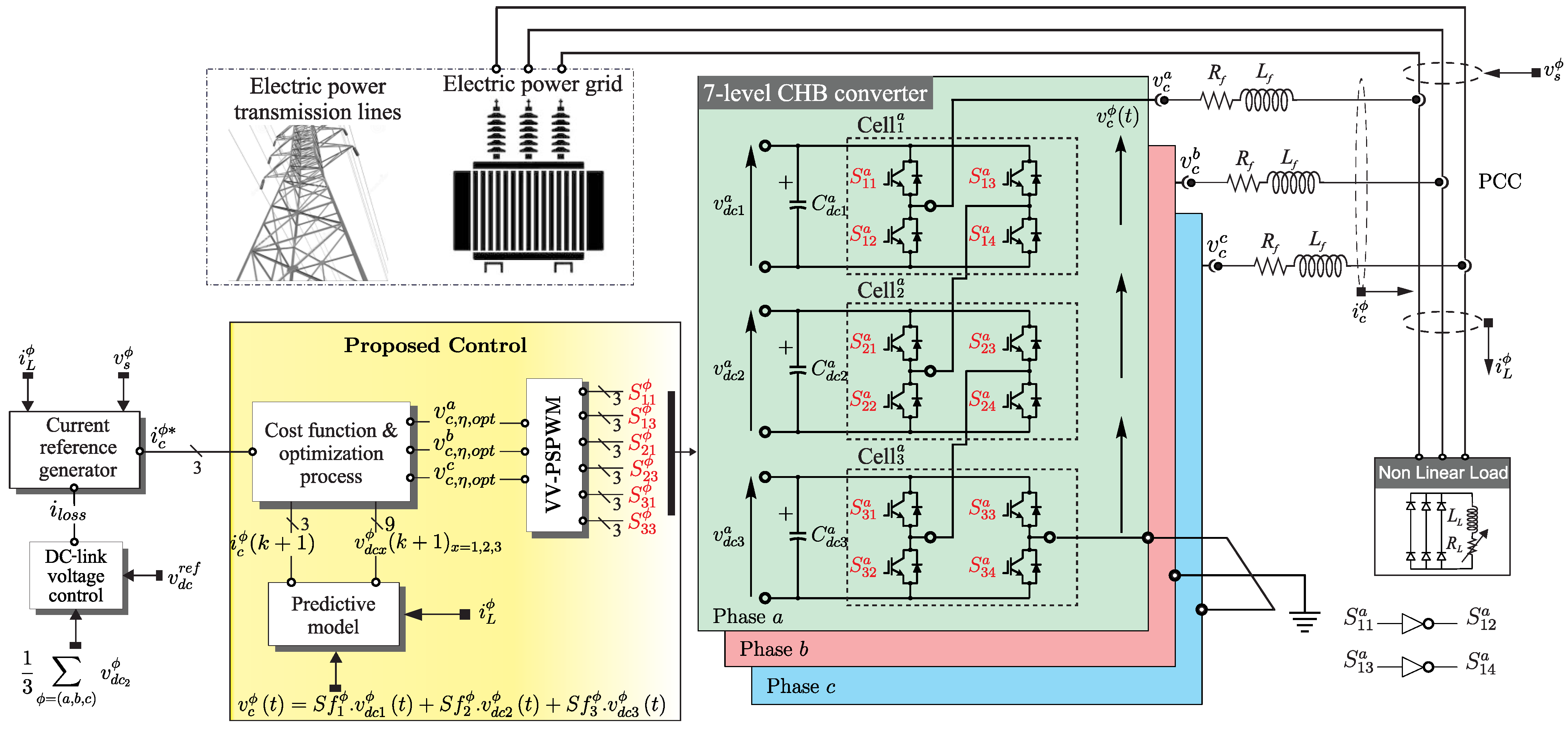
2. Multimodular APF Model

Figure 1 shows the control scheme applied to the multimodular APF based on the 7-level 3-phase CHB multilevel converter. Note that each cell of the CHB has an independent DC-link and four switching devices based on the SiC-MOSFET semiconductors. The 7-level 3-phase converter topology is implemented by connecting three cells in series per phase. Then, 36 firing signals, represented by S x y ϕ { 0 , 1 } , are used to control each cell, ϕ being the phase ( ϕ = a, b, or c), x the cell number in each phase ( x = 1 , 2 , 3 ), and y the switching device in each cell ( y = 1, 2, 3, or 4). Table 1 shows a combination of the firing signals taking phase “a” as an example in order to generate 7 voltage levels at the output of the 7-level converter. A similar analysis can be extended to other phases considering allowable combinations and avoiding short circuits in the DC-link of each cell.
To obtain an equation that describes the dynamics of the converter output voltage, the switching function of the CHB multilevel converters S f x is used. This is derived for each phase and H-bridge cell as:
S f x ϕ = S x 1 ϕ . S x 4 ϕ S x 2 ϕ . S x 3 ϕ
The value of S f x ϕ indicates the charging and discharging among the DC-link capacitors C d c 1 ϕ , C d c 2 ϕ , and C d c 3 ϕ . Supposing the current i c ϕ flows from the converter to the grid, then the capacitor C d c x ϕ is charging if S f x ϕ = 1 , discharging if S f x ϕ = 1 , and unchanged if S f x ϕ = 0 . The output voltage of the multilevel converter depends on the switching function and the voltage in each of the DC-link capacitors and can be expressed as:
v c ϕ t = S f 1 ϕ . v d c 1 ϕ t + S f 2 ϕ . v d c 2 ϕ t + S f 3 ϕ . v d c 3 ϕ t
The values of v d c 1 ϕ , v d c 2 ϕ , and v d c 3 ϕ are the estimated voltages of each DC-link previously filtered. They may not be equal to their reference voltage due to the dynamics of the system.
According to Kirchhoff’s law for the DC side and considering the ideal case ( R d c = , where R d c is a resistor that concentrates the overall losses in the DC side), the currents flowing into the electrical grid from capacitors C d c 1 ϕ , C d c 2 ϕ , and C d c 3 ϕ , whose capacitance values C d c x ϕ = C d c , can be expressed as:
i C x ϕ t = C d c . d v d c x ϕ d t = S f x ϕ . i c ϕ
On the other hand, the proposed controller is based on the explicit APF mathematical model in order to calculate the effects of control actions over the evolution of the state variables. The dynamics of the system’s model can be obtained by using Kirchhoff’s circuit laws. Notice that the APF based on the CHB 7-level converter is connected at the PCC. Next, by applying Kirchhoff’s laws for the AC side of the APF and using (2) and (3), assuming the currents flow from the converter to the electrical grid, the following equations in the state-space representation are obtained for each phase:
i c ϕ t . v d c 1 ϕ t . v d c 2 ϕ t . v d c 3 ϕ t . = F . i c ϕ t v d c 1 ϕ t v d c 2 ϕ t v d c 3 ϕ t + G . v s ϕ t 0 0 0
where v s ϕ ( t ) ϕ ∈{ a , b , c } are the grid voltages and i c ϕ ( t ) and v c ϕ ( t ) are the APF output currents and voltages, respectively. The matrices F and G are:
F = R f L f S f 1 ϕ L f S f 2 ϕ L f S f 3 ϕ L f S f 1 ϕ C 0 0 0 S f 2 ϕ C 0 0 0 S f 3 ϕ C 0 0 0
G = 1 L f 0 0 0 0 0 0 0 0 0 0 0 0 0 0 0
R f being the parasitic (series) resistance of the inductive filter  L f connected between the output of the multilevel converter and the PCC.

3. Predictive Model

The predictive model can be obtained from (4) by using a forward-Euler discretization method. Euler’s method is the most basic explicit method for numerical integration of ordinary differential equations and consequently carries a low computational burden, which benefits the experimental implementation [28,29,30]. The APF discrete-time model is given by:
i ^ c ϕ k + 1 v ^ d c 1 ϕ k + 1 v ^ d c 2 ϕ k + 1 v ^ d c 3 ϕ k + 1 = A . i c ϕ k v d c 1 ϕ k v d c 2 ϕ k v d c 3 ϕ k + B . v s ϕ k 0 0 0
where:
A = 1 R f T s L f T s . S f 1 ϕ L f T s . S f 2 ϕ L f T s . S f 3 ϕ L f T s . S f 1 ϕ C 1 0 0 T s . S f 2 ϕ C 0 1 0 T s . S f 3 ϕ C 0 0 1
B = T s L f 0 0 0 0 0 0 0 0 0 0 0 0 0 0 0
T s being the sampling time.

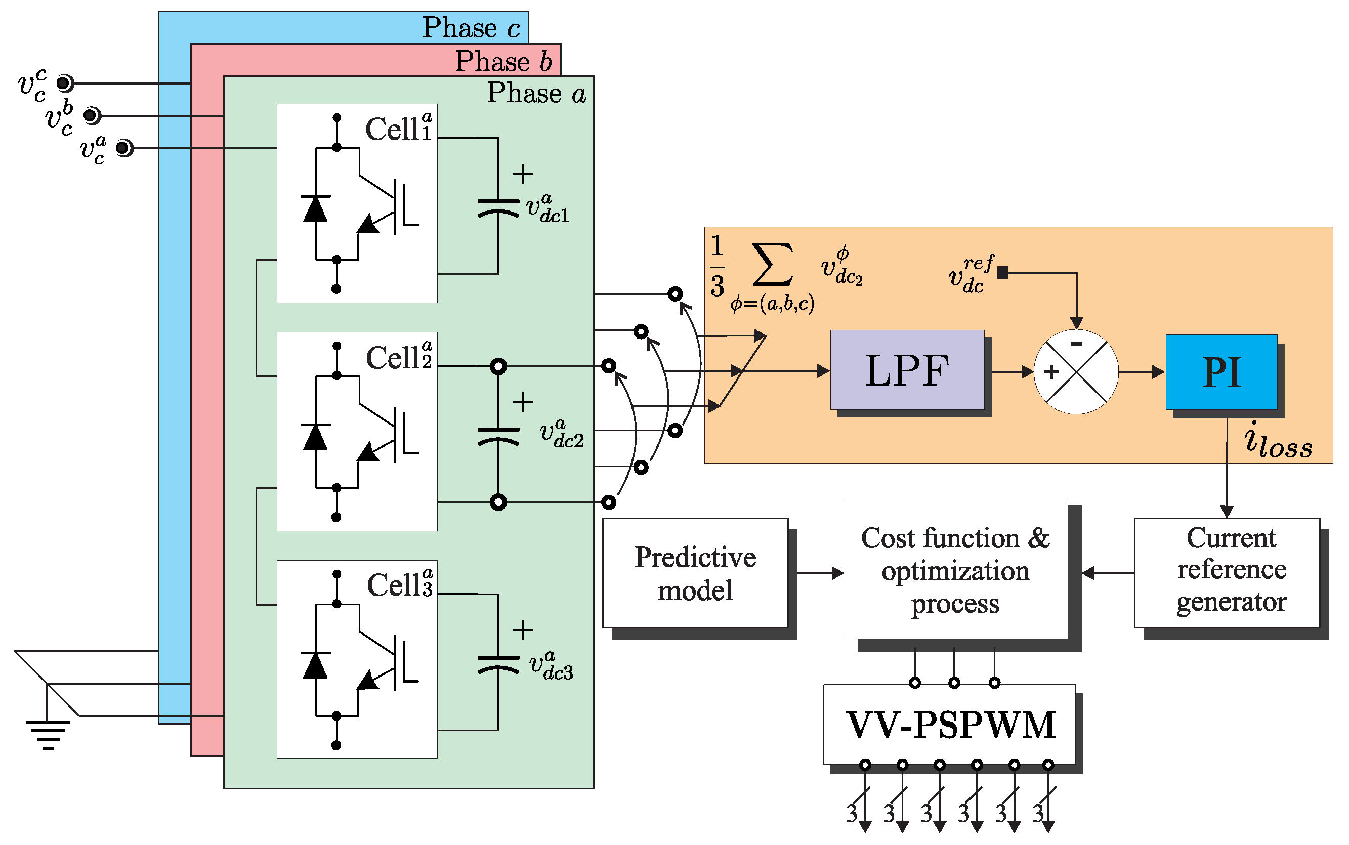
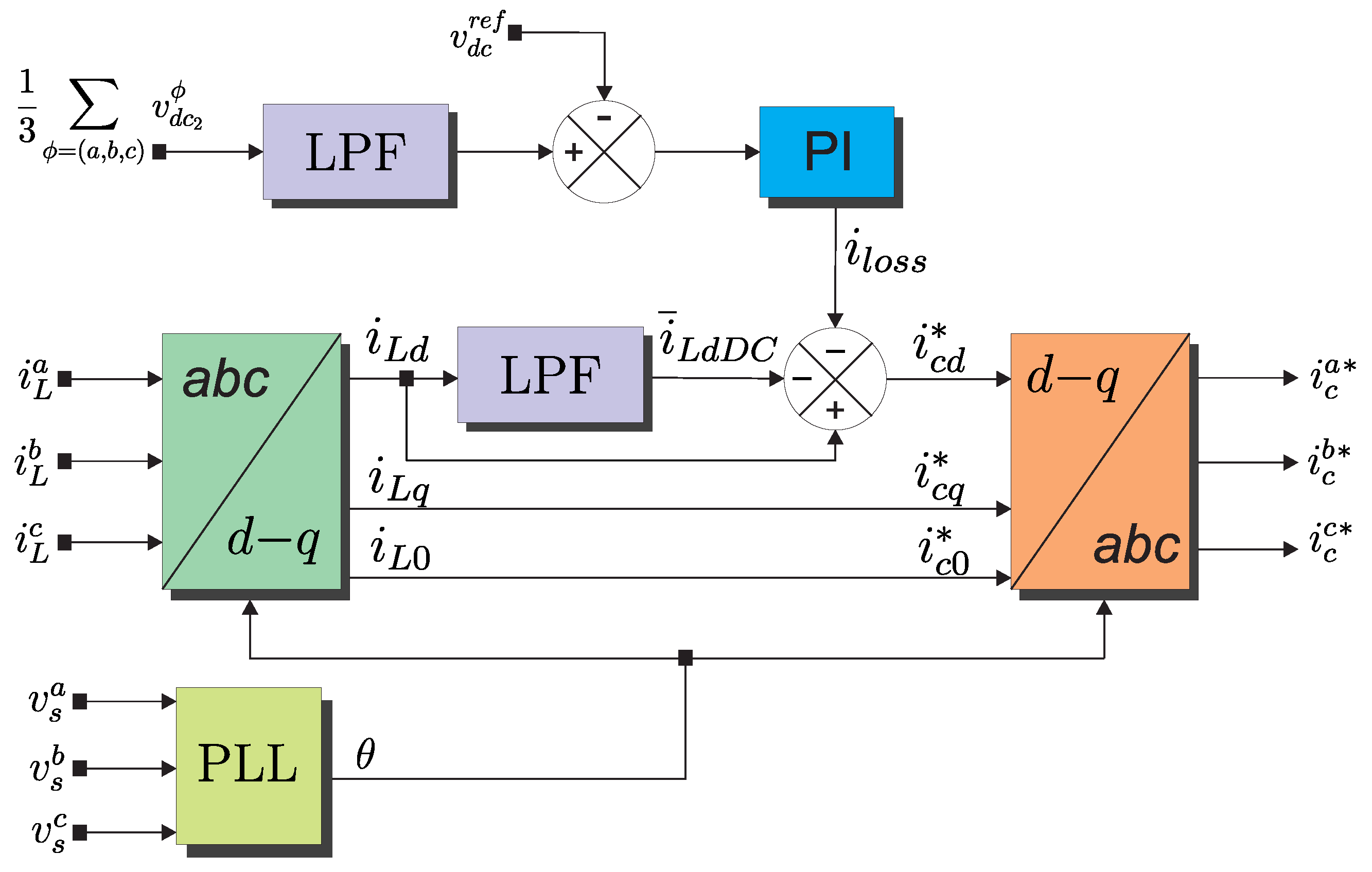
3.1. Current Reference Generation

The proposed controller requires the calculation of the reference currents in order to evaluate the cost function in (18). Figure 2 illustrates the block diagram of the current reference calculation based on synchronous reference frame (SRF) theory. As can be seen from Figure 2, the current reference generation block diagram requires the measurement of the capacitor voltages, load currents, and source voltages. The phase currents and voltages are represented in the d q 0 subspace by using Park’s transformation matrix:
T d q = 2 3 cos ( θ ) cos ( θ 2 π 3 ) cos ( θ + 2 π 3 ) sin ( θ ) sin ( θ 2 π 3 ) sin ( θ 2 π 3 ) 1 2 1 2 1 2
The use of a three-phase PLL is required to synchronize these signals with the source voltages. Due to the nonlinear loads, the components d q can be decomposed into two elements, one DC component i ¯ L d D C associated with the 50 Hz fundamental frequency power and the other one i ˜ L d associated with the harmonic frequencies. The currents in the d and q axes can be represented as the sum of their fundamental and harmonic components as follows:
i L d = i ¯ L d D C + i ˜ L d i L q = i ¯ L q + i ˜ L q
The DC component of the current i ¯ L d D C is separated using a digital second-order low-pass filter (LPF), as shown in the scheme of Figure 2. The reference currents in the time domain, based on the references i c d * , i c q * , and i c 0 * , are:
i c ϕ * = [ T d q ] 1 . i c d * i c q * i c 0 *
where:
i c d * = i L d i ¯ L d D C i l o s s
i c q * = i L q
The term i l o s s in (13) is the additional power needed to increase the average voltage across the DC-link capacitors and to balance the losses of the 7-level CHB converter associated with the switching states. This current i l o s s is obtained by using a PI controller.

3.2. DC-Link Voltage Control

Depending on how the filter injects current into the electrical power grid, the DC-link capacitors release or absorb energy, causing a drop or increase, respectively, in the v d c ϕ voltage of the capacitors. On the other hand, semiconductor losses by switching and conduction also cause a reduction of the capacitor voltages. That is why a regulation system is needed that maintains the voltage levels at a certain average reference value. To regulate the average capacitor voltages to reference values in the CHB 7-level converter, a common methodology is based on the measurement of each capacitor voltage in order to evaluate the error to implement a PI controller in discrete-time [31,32]. This procedure represents an optimal solution to the capacitor voltage regulation process; however, it increases the complexity of the overall system, especially when considering the multilevel converter. A different approach is based on the modification of the cost function of predictive control, including a term that seeks to achieve the capacitor voltages’ balance by applying an optimal switching function at each sampling period [33,34].
In this work, a suboptimal solution was proposed combining both approaches. The implemented DC-link voltage controller is shown in Figure 3. As can be seen from Figure 3, the voltage measurements performed made only in the middle cell. These capacitor voltages are used in the predictive model block to predict their voltage level, and an average of these measurements is used to calculate the voltage error applied to the PI control block, through an LPF. According to [35], an approximation to the proportional ( k p ) and integral ( k i ) gain values can be written as:
e k ϕ = v d c r e f v d c 2 ϕ i l o s s ϕ = i l o s s ( k 1 ) + k p . ( e k ϕ e k 1 ϕ ) + T m p i . k i . e k ϕ
i l o s s = 1 3 ϕ = a , b , c i l o s s ϕ
k p = C d c 2 . T c k i = k p 2
where e k ϕ represents the error between the reference and the previously filtered measured voltages v d c 2 ϕ , then the loss current i l o s s is calculated, i l o s s ( k 1 ) being the loss current estimated in the previous instant, e ( k 1 ) the voltage error calculated in the previous instant, T m p i the PI controller actuation time, and finally, i l o s s , which represents the sum of the loss currents of each phase with respect to the middle cell.

3.3. Cost Function and Optimization Process

The proposed controller was based on model-based predictive control to follow the current references and simultaneously achieve a balance in the capacitor voltages. The MPC was based on the optimization process in which a cost function is minimized. This cost function is defined as the difference between the reference values and the estimates obtained through the prediction model. In the three-phase control scheme, a general cost function is defined for each phase, which includes the reference current tracking error and the voltage tracking error for the capacitors, which are independently evaluated using the following equation:
g ϕ = i c ϕ * i ^ c ϕ k + 1 2 + λ v d c r e f v ^ d c 2 ϕ ( k + 1 ) 2
where λ is a weight factor in the optimization process.
Next, the optimization algorithm selects the optimum vector S η , o p t ϕ for each firing signal of each cell by the evaluation and minimization of the predefined multi-objective cost function represented by (18). Algorithm 1 summarizes the optimization process.
Algorithm 1 Optimization algorithm.
1  Initialize g o p t a : = , g o p t b : = , g o p t c : = , η : = 0
2 Compute the APF current references (12).
3 while η 7 do
4     S η ϕ S x y ϕ x & y = 1 , 2 , 3
5     Compute the output voltage of the multilevel converter (2).
6     Calculate the APF prediction currents and voltage (4).
7     Compute the cost function (18).
8     if  g a < g o p t a  then
9        g o p t a g a , S η , o p t a S η a
10   end if
11    if  g b < g o p t b  then
12        g o p t b g b , S η , o p t b S η b
13    end if
14    if  g c < g o p t c  then
15        g o p t c g c , S η , o p t c S η c
16    end if
17    η : = η + 1
18 end while
19 Compute the modulation signals (19).
20 Obtain the turn-on times of the firing signals according to Figure 4.
21 Apply the firing signals.
Figure 4. PSPWM waveform generation.
Energies 14 04698 g004

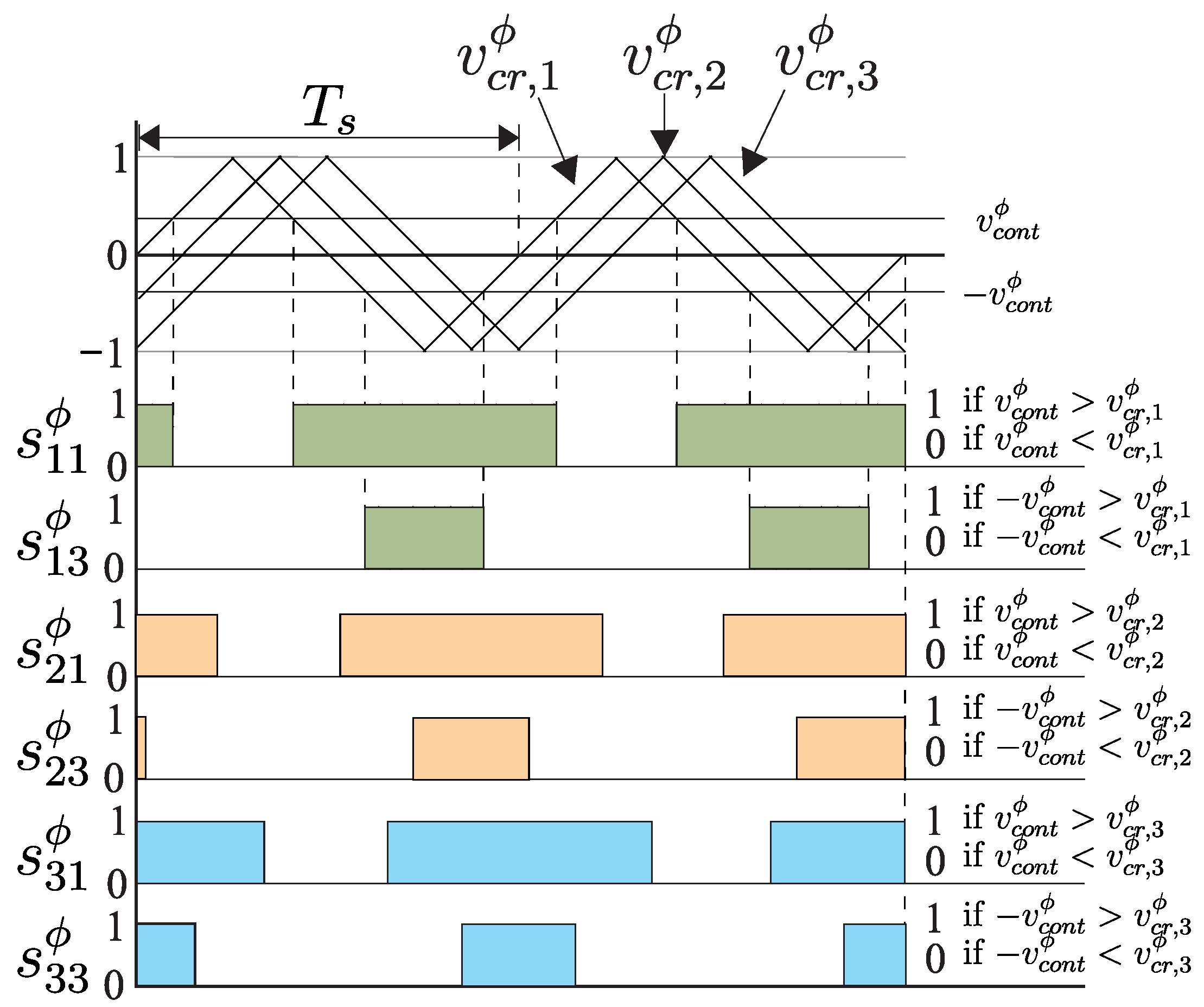
3.4. Voltage Vectors’ Phase-Shifted PWM Strategy

After selecting the optimal vector S η , o p t ϕ , which corresponds to an optimal voltage v c , η , o p t ϕ given by (2), the classic solution is to apply this output voltage during one sampling period. However, the proposed method uses a modulation stage based on the phase-shifted pulse width modulation (PSPWM) approach. Three phase-shifted triangular carrier waves (with the same frequency and magnitude peak-to-peak) are needed to obtain the turn-on times of the firing signals of each cell. The phase-shift between the two adjacent carriers is 180 /3. By comparing one specific carrier wave v c r , x ϕ with a pair of inverted modulation signals v c o n t ϕ and v c o n t ϕ , we obtain the firing signals of s x 1 ϕ and s x 3 ϕ , as shown in Figure 4. Note that the carrier frequency is equal to the sampling frequency, and the modulation signals are normalized between −1 and 1. The modulated signals are associated with the optimal voltages as:
v c o n t ϕ = v c , η , o p t ϕ 3 v d c r e f .

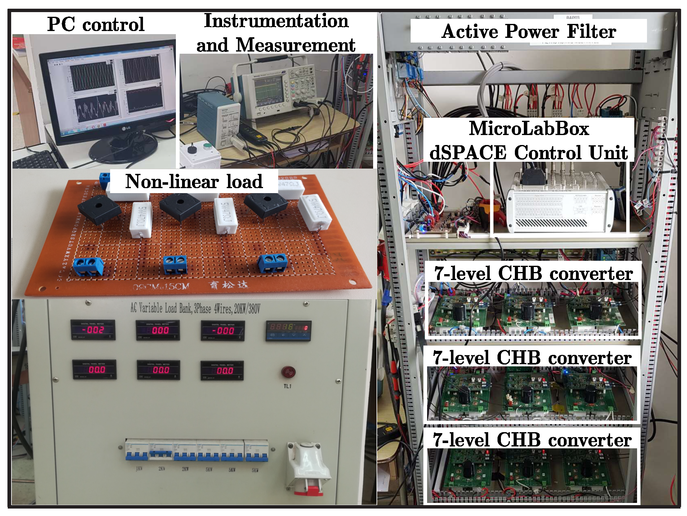
4. Experimental Test Bench

The multimodular APF built for experimental validation is shown in Figure 5. The test bench integrated three individual CHB cells per phase, interconnected in series. Control signals were conditioned in independent driver boards and were transmitted from the control board to the drivers by using fiber optics in order to avoid electromagnetic noises from the switching devices in the control signals. The control board was based on the dSPACE MicroLabBox multipurpose control system. The power semiconductor devices used were SiC-MOSFETs from Cree, CAS120M12BM2, with 120 A and 1200 V maximum drain–source current and drain–source voltage, respectively.
In order to apply the proposed controller, analog phase voltages and currents were measured using a multimodular PCB. The analog signals were digitized by using the dSPACE MicroLabBox analog-to-digital converter (ADC) modules with 16 bit resolution. Figure 5 shows the current and voltage measurement boards designed to obtain the electrical variables necessary for the implementation of the control algorithms. The sampling frequency was 18 kHz, which was the same as the equivalent switching frequency, and the carrier frequency for PWM modulation was 1 kHz.

5. Experimental Validation

In order to verify the performance of the proposed APF, this section shows the experimental results considering v s ϕ =120 Vrms, v d c r e f = 75 V, L f = 10 mH. The nonlinear load was a three-phase rectifier. The DC side of the bridge rectifier was connected to an RL load with R L = 100 Ω , 50 Ω , 25 Ω , and L L = 114 mH, respectively. The capacitance of the DC-link in all DC cells ( C d c ) was 20,000 μF. The defined cost function in (18) with λ = 0.02 was selected to evaluate the performance of the proposed controller, prioritizing the current tracking as the first control objective and the DC-link tracking voltage as the second objective.

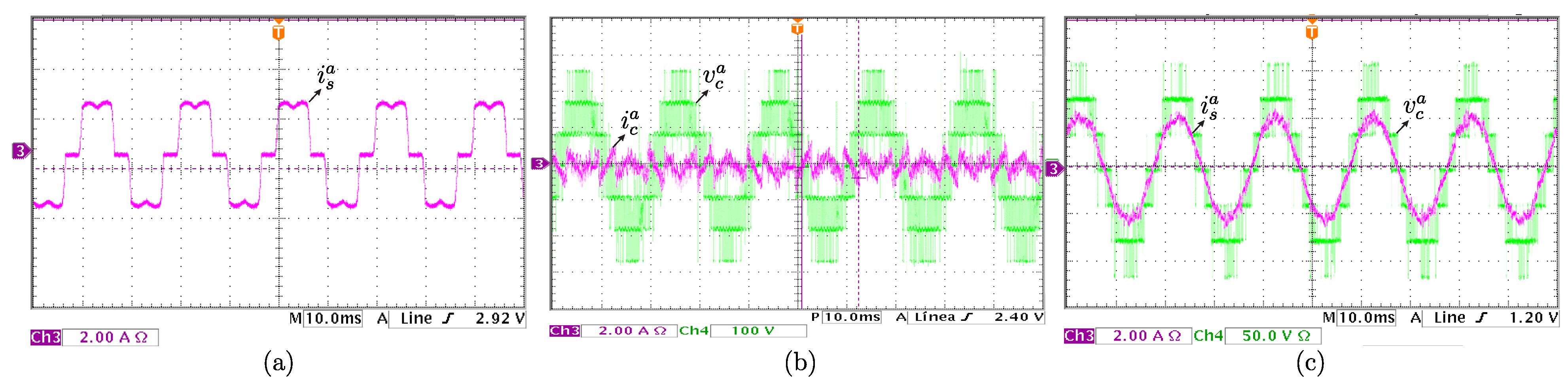
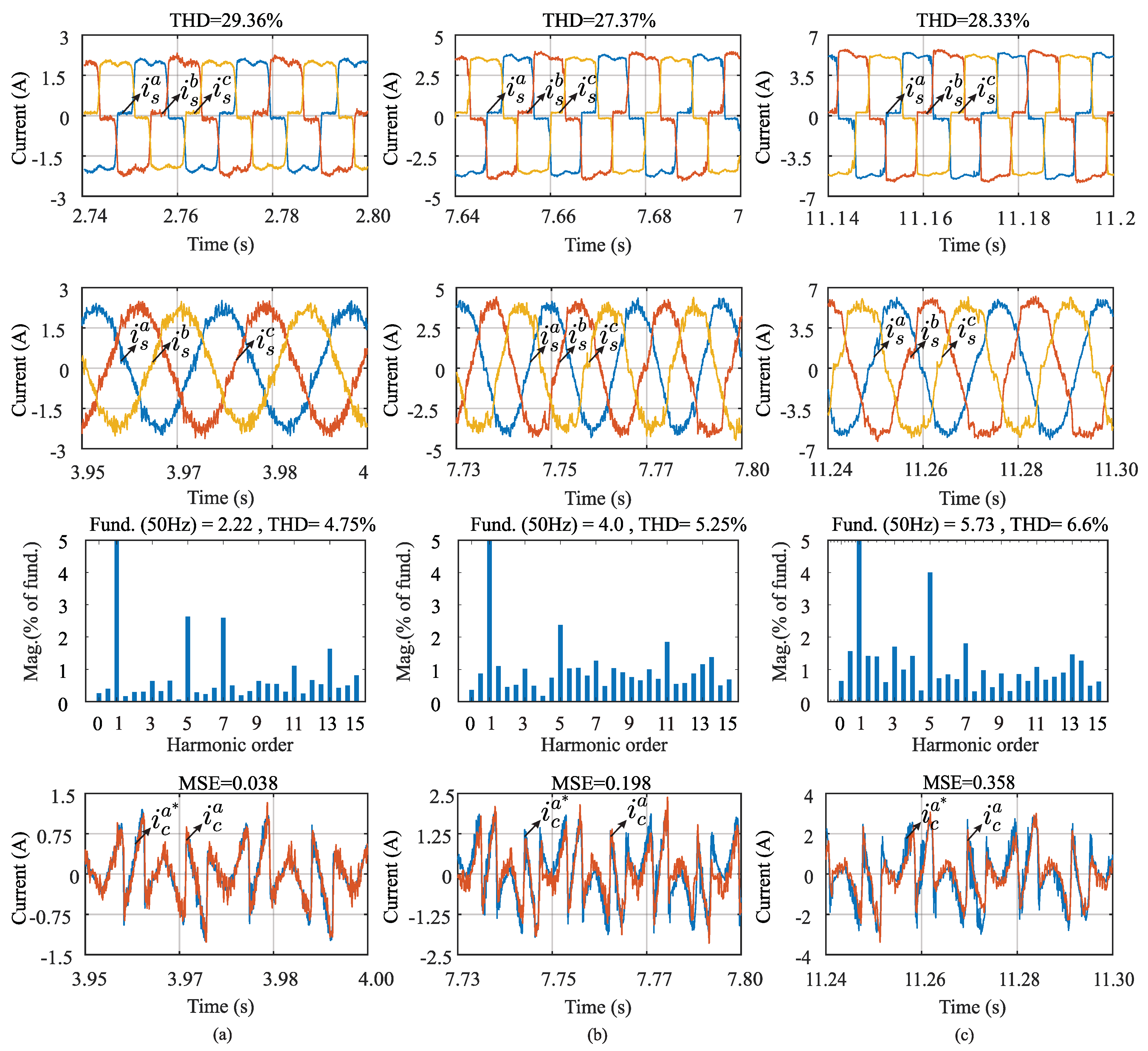
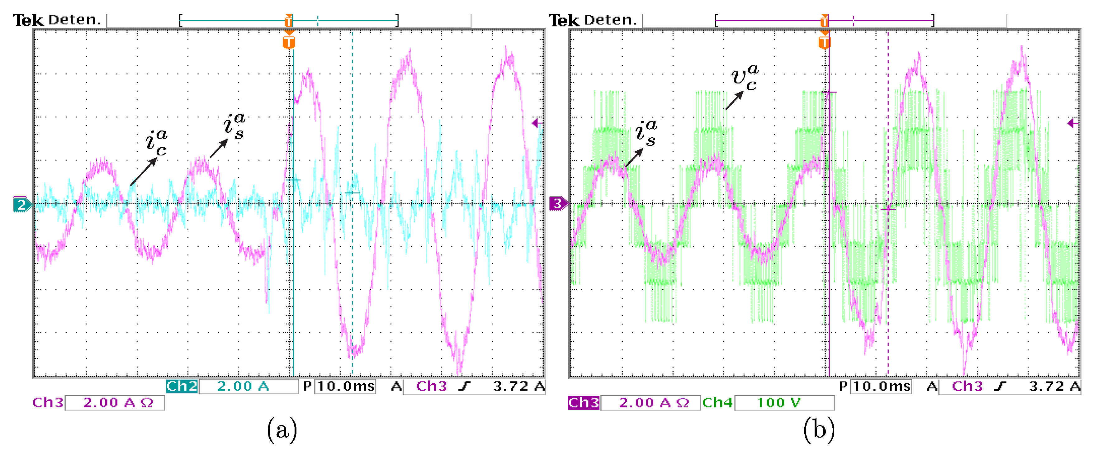
5.1. Verification of the Harmonics Compensation

The harmonics compensation performance was tested by using a nonlinear load under different grid current conditions. The experimental results of the total harmonic distortion (THD) were obtained by using the data captured with the control desk software of the dSPACE MicroLabBox. Load currents ( i L ), APF output currents ( i c ), grid currents ( i s ), as well as source voltages ( v s ) and DC-link ( V d c ) voltages were captured and analyzed. Figure 6 shows the THD level in the grid side before compensation considering three operating points R L = 100 Ω , 50 Ω , and 25 Ω , respectively. Under these operating conditions, the THD of the currents at the grid side was 29.36%, 27.37%, and 28.33%, respectively. Once the APF was connected, the compensation process started. The output APF currents ( i c ) were injected at the PCC in order to compensate the harmonics distortion at the grid side. According to the grid currents’ evolution shown in Figure 6, after connecting the APF, currents at the grid side ( i s ) quickly became sinusoidal. The THD level in the grid currents decreased to the values of 4.75%, 5.25%, and 6.6%, respectively, for each load impedance value. A significant improvement in terms of harmonic compensation was observed.
To quantify the performance of the proposed MPC based on the PSPWM algorithm, the mean-squared error (MSE) between the reference currents calculated by (12) and the measured current captured by the ADC of the dSPACE MicroLabBox were used as the figure of merit. According to the results shown in Figure 6, the MSE increased as the load power increased, being able to quantify in 0.038A, 0.198A, and 0.358A, respectively. On the other hand, Figure 7a shows the source current evolution ( i s a ) at the grid side. It shows the distortions due to the high level of THD existing in the electrical grid due to the nonlinear load connected at the PCC. Once the APF was enabled, the current injection ( i c a ) at the PCC was produced by the APF in order to compensate the harmonics distortion of the source current, as shown in Figure 7b, where the CHB seven-level converter output voltage ( v c a ) is also shown. From Figure 7c, once the harmonics compensation process starts, a significant decrease can be observed in the THD level existing in the source current at the grid side ( i s a ).
In order to analyze the APF behavior under dynamic conditions, a load resistance ( R L ) variation from 150 Ω to 50 Ω was applied. Figure 8a presents the dynamic behavior of the APF current injection ( i c a ) at the PCC in order to produce the harmonics compensation at the grid side ( i s a ) where the measured grid current rapidly rose to the nominal value without oscillations that may affect the stability of the system. On the other hand, Figure 8b shows the dynamic behavior of the APF output voltage ( v c a ) produced by the load resistance variation. It can be seen how from the transient condition, the duty cycle of the APF output voltage was modified in order to generate a current compensation ( i c a ) with greater amplitude injected at the PCC, resulting in a compensated current at the grid side ( i s a ) with a low harmonic content, even instantaneously after the transient condition.

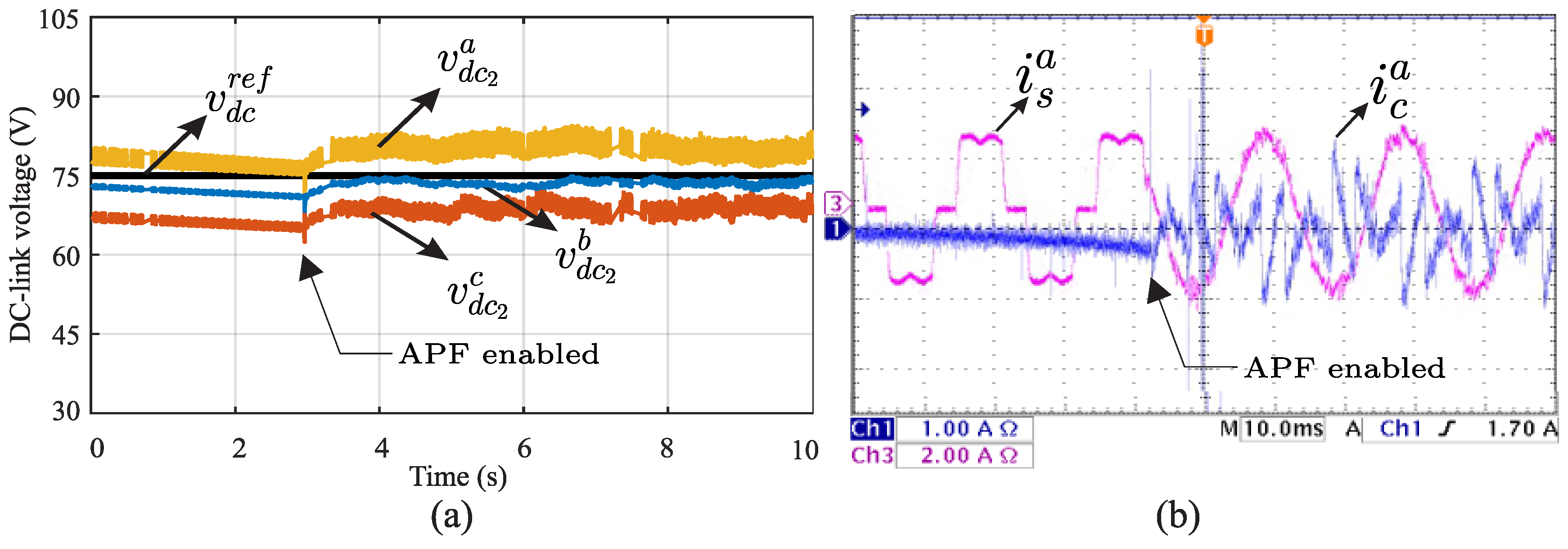
5.2. Verification of the DC-Link Voltage Control

In order to verify the effects of the DC-link voltage control under the transient condition, the APFs were intentionally disabled during the steady-state. After three seconds, the APF was suddenly connected, causing a transient in the DC-link voltages. Figure 9a shows the experimental waveforms of capacitor voltages under transient conditions. According to the experimental results, the PI control implemented on three cells was enough to achieve the stable behavior of the DC-link voltages. Once the APF was enabled, the capacitor voltages converged to their reference value. Figure 9b shows the harmonics compensation in the source current at the grid side when the APF was connected at the PCC. The experimental results demonstrated in Figure 6, Figure 7, Figure 8 and Figure 9 confirmed the feasibility and effectiveness of the proposed controller.

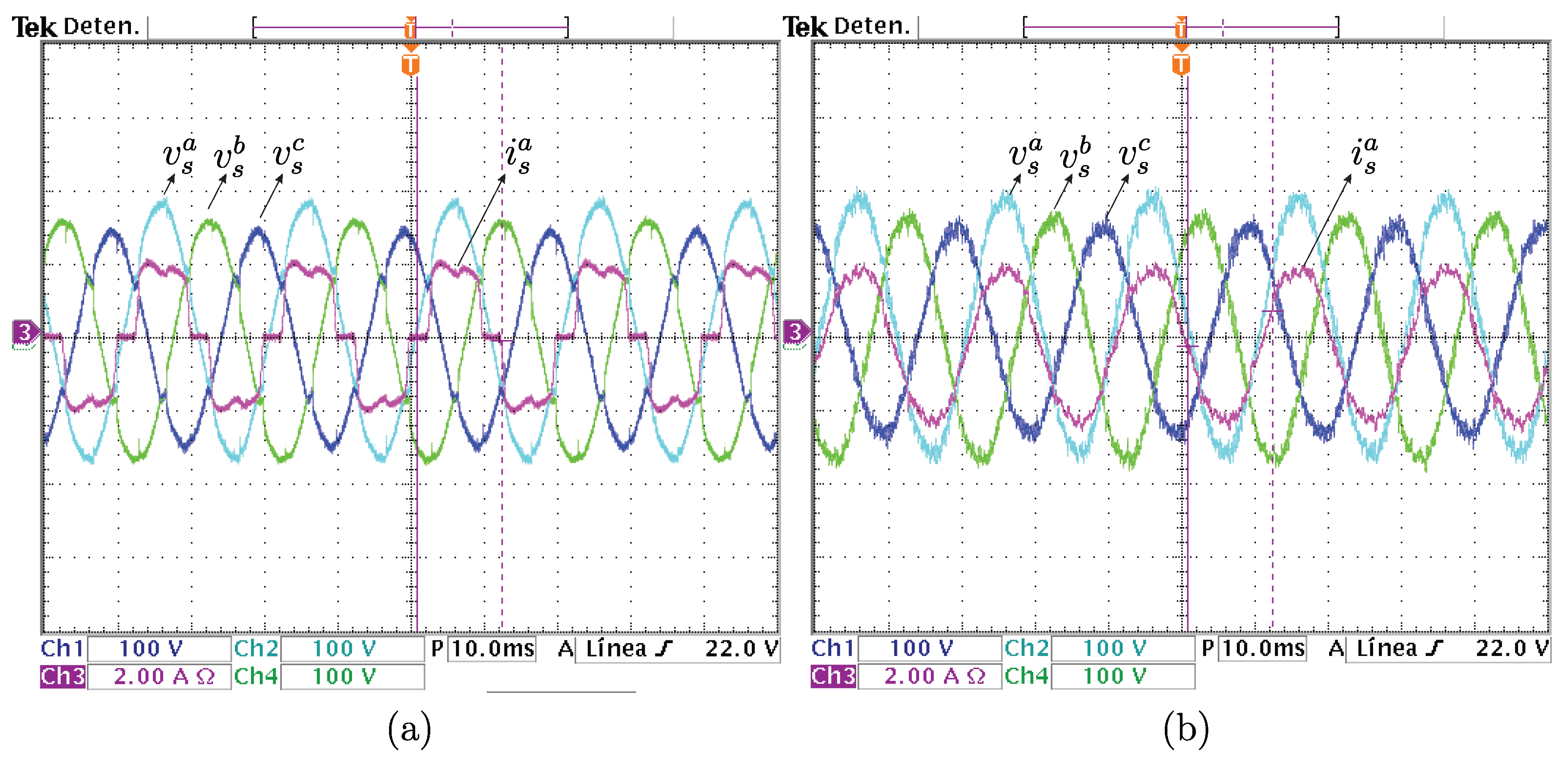
5.3. Verification of the Compensation for Unbalanced Voltages

Main currents may be unbalanced if nonlinear loads or AC source voltages are unbalanced. Figure 10a shows the measured phase voltage waveforms for the unbalanced grid voltages and nonlinear load conditions. The voltage amplitude unbalance was 20 % for the experiment. Under these operating conditions, the active power filter operated properly, reducing the harmonic distortions at the grid side, as shown in Figure 10b.

6. Conclusions

This paper presented the implementation of a multimodular H-bridge SiC-MOSFET-based APF using a simple and novel controller combining the concepts of model-based predictive control, voltage vector PSPWM, and suboptimal DC-link voltage control. The feasibility and effectiveness of the overall system was investigated and validated through experimental results. In this regard, the proposed system proved to be viable to compensate the current harmonics distortion at the grid side generated by nonlinear loads. The fifth and seventh harmonics originally present in the grid currents, with 27.30% of the THD value, were compensated after the interconnection of the APF at the PCC. The reduction of the THD of the grid currents from 27.30% to 4.75% proved the quality of the power system would be enhanced. This characteristic was evaluated under different operating points. The controller was found to be effective, and its validity was demonstrated based on the experimental results through the analysis of the MSE in the tracking reference currents obtained by the SRF theory, under both steady-state and dynamic conditions. From the point of view of the harmonics compensation of the current at the grid side, the proposed algorithm showed a good dynamic response even under transient operating regimes and unbalanced voltages.

Author Contributions

Conceptualization, R.G., J.P., A.E., A.R. and L.C.; methodology, R.G., J.P. and A.E.; software, A.E., A.R. and L.C.; validation, R.G., J.P., A.E. and A.R.; formal analysis, R.G., J.P., A.E., A.R. and L.C.; investigation, R.G., J.P., A.E., A.R. and L.C.; resources, R.G., J.P., A.E., A.R., L.C. and M.A.; data curation, R.G., J.P., A.E., A.R. and L.C.; writing, original draft preparation, R.G., J.P., A.E. and M.A.; writing, review and editing, R.G. and M.A.; visualization, R.G., J.P., A.E. and M.A.; project administration, R.G. and M.A.; funding acquisition, R.G. All authors read and agreed to the published version of the manuscript.

Funding

This research was funded through the Consejo Nacional de Ciencia y Tecnología (CONACYT)-Paraguay, Grant Number POSG16-05 and Grant 14-INV-096.

Institutional Review Board Statement

Not applicable.

Informed Consent Statement

Not applicable.

Data Availability Statement

Not applicable.

Conflicts of Interest

The authors declare no conflict of interest.

Abbreviations

The following abbreviations were employed in this work:
ACAlternating current
ADCAnalog-to-digital converter
APFActive power filter
CHBCascade H-bridge
CPDsCustom power devices
DCDirect current
DERsDistributed energy resources
DVRDynamic voltage restorer
IGBTIsolated gate bipolar transistors
LPFLow-pass filter
MOSFETMetal–oxide–semiconductor field-effect transistor
MPCModel predictive control
MSEMean-squared error
PCBPrinted circuit board
PCCPredictive current control
PIProportional–integral
PLLPhase-locked loop
PSPWMPhase-shifted PWM
PWMPulse width modulation
SiCSilicon carbide
SRFSynchronous reference frame
THDTotal harmonic distortion
UPQCUnified power quality conditioners
VSCsVoltage source converters
VVVoltage vectors
Nomenclature
ϕ Phase of power grid a, b, and c
S x y ϕ Firing signals
xCorresponding cell number
ySwitching device in each cell
CCapacitor
v d c x ϕ Voltages measured in the DC-link
v c ϕ Converter voltage output
i C x ϕ Current estimation in the capacitor
i c ϕ APF measured current
i L ϕ Load measured current
i s ϕ Power grid measured current
v s ϕ Voltage measurement in the power grid
R f Filter resistance
L f Filter inductance
i . c ϕ ( k + 1 ) APF current prediction
v . c x ϕ ( k + 1 ) APF voltage prediction
T s Sample time
v d c r e f DC-link voltage reference
i L d Active power load in synchronous frame
i L q Reactive power load in synchronous frame
i ¯ L d D C continuous component of i L d
i ˜ L d alternating component of i L d
i c d * Active power reference in synchronous frame
i c q * Reactive power reference in synchronous frame
θ Phase angle calculated by the PLL
i l o s s Estimation of the current required to charge the capacitors
T d q Transformation matrix a , b , c to d q
T d q 1 Inverse transformation matrix d q to a , b , c
i c ϕ * Reference current of phases a, b, and c.
e k ϕ Error between the reference and measured voltages
e k 1 ϕ Voltage error calculated in the previous instant
i l o s s a + b + c Sums of the loss currents of each phase
i l o s s ( k 1 ) Loss current calculated in the previous instant
T m p i PI controller actuation time
k p PI proportional constant
k i PI integral constant
S η , o p t ϕ Optimum vector
v c , η , o p t ϕ Optimal voltage
v c r , x ϕ Carrier wave
v c o n t ϕ Modulation signals

References

  1. Dash, S.K.; Ray, P.K. Power quality improvement utilizing PV fed unified power quality conditioner based on UV-PI and PR-R controller. CPSS Trans. Power Electron. Appl. 2018, 3, 243–253. [Google Scholar] [CrossRef]
  2. Zaidi, A.H.; Sunderland, K.; Conlon, M. Role of reactive power (STATCOM) in the planning of distribution network with higher EV charging level. IET Gener. Transm. Distrib. 2019, 13, 951–959. [Google Scholar] [CrossRef]
  3. Elmetwaly, A.H.; Eldesouky, A.A.; Sallam, A.A. An Adaptive D-FACTS for Power Quality Enhancement in an Isolated Microgrid. IEEE Access 2020, 8, 951–959. [Google Scholar] [CrossRef]
  4. Badoni, M.; Singh, A.; Singh, B.; Saxena, H. Real-time implementation of active shunt compensator with adaptive SRLMMN control technique for power quality improvement in the distribution system. IET Gener. Transm. Distrib. 2020, 14, 1598–1606. [Google Scholar] [CrossRef]
  5. Gregor, R.; Pacher, J.; Renault, A.; Comparatore, L.; Rodas, J. Experimental Validation of the DSTATCOM Based on SiC-MOSFET Multilevel Converter for Reactive Power Compensation. J. Syst. Cybern. Inform. 2020, 18, 57–61. [Google Scholar]
  6. Pradhan, M.; Mishra, M.K. Dual P-Q Theory Based Energy-Optimized Dynamic Voltage Restorer for Power Quality Improvement in a Distribution System. IEEE Trans. Ind. Electron. 2018, 66, 2946–2955. [Google Scholar] [CrossRef]
  7. Lakshmi, S.; Ganguly, S. An On-Line Operational Optimization Approach for Open Unified Power Quality Conditioner for Energy Loss Minimization of Distribution Networks. IEEE Trans. Power Syst. 2019, 34, 4784–4795. [Google Scholar] [CrossRef]
  8. Choudhury, S.R.; Das, A.; Anand, S.; Tungare, S.; Sonawane, Y. Adaptive shunt filtering control of UPQC for increased nonlinear loads. IET Power Electron. 2019, 12, 330–336. [Google Scholar] [CrossRef]
  9. Wang, J.; Xing, Y.; Wu, H.; Yang, T. Dual-DC-Port Dynamic Voltage Restorer With Reduced-Rating Integrated DC-DC Converter for Wide-Range Voltage Sag Compensation. IEEE Trans. Power Electron. 2018, 34, 7437–7449. [Google Scholar] [CrossRef]
  10. Li, P.; Xie, L.; Han, J.; Pang, S.; Li, P. A new voltage compensation philosophy for dynamic voltage restorer to mitigate voltage sags using three-phase voltage ellipse parameters. IEEE Trans. Power Electron. 2017, 33, 1154–1166. [Google Scholar] [CrossRef]
  11. Myneni, H.; Kumar, G.S. Simple algorithm for current and voltage control of LCL DSTATCOM for power quality improvement. IET Gener. Transm. Distrib. 2019, 13, 423–434. [Google Scholar] [CrossRef]
  12. Dheepanchakkravarthy, A.; Jawahar, M.R.; Venkatraman, K.; Selvan, M.P.; Moorthi, S. Performance evaluation of FPGA-based predictive current controller for FL-DSTATCOM in electric distribution system. IET Gener. Transm. Distrib. 2019, 13, 4400–4409. [Google Scholar] [CrossRef]
  13. Busarello, T.D.C.; Mortezaei, A.; Paredes, H.K.M.; Al-Durra, A.; Pomilio, J.A.; Simoes, M.G. Simplified small-signal model for output voltage control of asymmetric cascaded H-bridge multilevel inverter. IEEE Trans. Power Electron. 2018, 33, 3509–3519. [Google Scholar] [CrossRef] [Green Version]
  14. Ghat, M.B.; Shukla, A. A new H-bridge hybrid modular converter (HBHMC) for HVDC application: Operating modes, control, and voltage balancing. IEEE Trans. Power Electron. 2018, 33, 6537–6554. [Google Scholar] [CrossRef]
  15. Zhang, L.; Yuan, X.; Wu, X.; Shi, C.; Zhang, J.; Zhang, Y. Performance evaluation of high-power SiC MOSFET modules in comparison to Si IGBT modules. IEEE Trans. Power Electron. 2019, 34, 1181–1196. [Google Scholar] [CrossRef]
  16. Fuentes, C.D.; Kouro, S.; Bernet, S. Comparison of 1700-V SiC-MOSFET and Si-IGBT Modules Under Identical Test Setup Conditions. IEEE Trans. Ind. Appl. 2019, 55, 7765–7775. [Google Scholar] [CrossRef]
  17. Mortezaei, A.; Simões, M.G.; Busarello, T.D.C.; Marafão, F.P.; Al-Durra, A. Grid-connected symmetrical cascaded multilevel converter for power quality improvement. IEEE Trans. Ind. Appl. 2018, 54, 2792–2805. [Google Scholar] [CrossRef] [Green Version]
  18. Tanaka, T.; Ma, K.; Wang, H.; Blaabjerg, F. Asymmetrical Reactive Power Capability of Modular Multilevel Cascade Converter Based STATCOMs for Offshore Wind Farm. IEEE Trans. Power Electron. 2018, 34, 5147–5164. [Google Scholar] [CrossRef]
  19. Ye, S.; Zhang, Y.; Xie, L.; Lu, H. Shunt active power filter based on proportional integral and multi vector resonant controllers for compensating nonlinear loads. J. Electr. Comput. Eng. 2018, 2018, 1312064. [Google Scholar] [CrossRef] [Green Version]
  20. Kasmieh, T.A.; Omran, H.S. Active power filter dimensioning using a hysteresis current controller. Resonance 2009, 1, 2. [Google Scholar]
  21. Najjar, M.; Shahparasti, M.; Heydari, R.; Nymand, M. Model Predictive Controllers With Capacitor Voltage Balancing for a Single-Phase Five-Level SiC/Si Based ANPC Inverter. IEEE Open J. Power Electron. 2021, 2, 202–211. [Google Scholar] [CrossRef]
  22. Renault, A.; Ayala, M.; Pacher, J.; Comparatore, L.; Gregor, R.; Toledo, S. Current control based on space vector modulation applied to three-phase H-Bridge STATCOM. In Proceedings of the 2020 IEEE International Conference on Industrial Technology (ICIT), Buenos Aires, Argentina, 26–28 February 2020; pp. 1066–1070. [Google Scholar]
  23. Renault, A.; Ayala, M.; Pacher, J.; Comparatore, L.; Gregor, R.; Rivera, M. Analysis of H-Bridge STATCOM with Fault Phase Controlled by Modulated Predictive Current Control. In Proceedings of the 2019 IEEE CHILEAN Conference on Electrical, Electronics Engineering, Information and Communication Technologies (CHILECON), Valparaiso, Chile, 13–27 November 2019; pp. 1–5. [Google Scholar]
  24. Renault, A.; Rodas, J.; Comparatore, L.; Pacher, J.; Gregor, R. Modulated predictive current control technique for a three-phase four-wire active power filter based on H-bridge two-level converter. In Proceedings of the 2018 53rd International Universities Power Engineering Conference (UPEC), Glasgow, UK, 4–7 September 2018; pp. 1–6. [Google Scholar]
  25. Comparatore, L.; Renault, A.; Pacher, J.; Rodas, J.; Gregor, R. Finite control set model predictive control strategies for a three-phase seven-level cascade H-bridge DSTATCOM. In Proceedings of the 2018 7th International Conference on Renewable Energy Research and Applications (ICRERA), Paris, France, 14–17 October 2018; pp. 779–784. [Google Scholar]
  26. Gao, H.; Zhang, P.; Liu, X.; Feng, S.; Ma, J.; Li, R. Seven-Level Active Power Filter Based on a Novel H-Bridge Power Topology Structure. Energies 2019, 12, 2997. [Google Scholar] [CrossRef] [Green Version]
  27. Wang, Y.; Wang, Y.; Chen, S.Z.; Zhang, G.; Zhang, Y. A Simplified Minimum DC-Link Voltage Control Strategy for Shunt Active Power Filters. Energies 2018, 11, 2407. [Google Scholar] [CrossRef] [Green Version]
  28. Ayala, M.; Doval-Gandoy, J.; Rodas, J.; Gonzalez, O.; Gregor, R.; Rivera, M. A Novel Modulated Model Predictive Control Applied to Six-Phase Induction Motor Drives. IEEE Trans. Ind. Electron. 2020, 68, 3672–3682. [Google Scholar] [CrossRef]
  29. Ayala, M.; Doval-Gandoy, J.; Rodas, J.; Gonzalez, O.; Gregor, R. Current control designed with model based predictive control for six-phase motor drives. ISA Trans. 2020, 98, 496–504. [Google Scholar] [CrossRef]
  30. Toledo, S.; Maqueda, E.; Rivera, M.; Gregor, R.; Wheeler, P.; Romero, C. Improved Predictive Control in Multi-Modular Matrix Converter for Six-Phase Generation Systems. Energies 2020, 13, 2660. [Google Scholar] [CrossRef]
  31. Panda, A.; Patnaik, S. Analysis of cascaded multilevel inverters for active harmonic filtering in distribution networks. Int. J. Electr. Power Energy Syst. 2014, 66, 216–226. [Google Scholar] [CrossRef]
  32. Vazquez, S.; Leon, J.; Carrasco, J.; Franquelo, L.; Galvan, E.; Reyes, M.; Sanchez, J.; Dominguez, E. Analysis of the Power Balance in the Cells of a Multilevel Cascaded H-Bridge Converter. IEEE Trans. Ind. Electron. 2010, 57, 2287–2296. [Google Scholar] [CrossRef]
  33. Zhang, Y.; Wu, X.; Yuan, X.; Wang, Y.; Dai, P. Fast Model Predictive Control for Multilevel Cascaded H-Bridge STATCOM with Polynomial Computation Time. IEEE Trans. Ind. Electron. 2016, 63, 5231–5243. [Google Scholar] [CrossRef]
  34. Gregor, R.; Comparatore, L.; Renault, A.; Rodas, J.; Pacher, J.; Toledo, S.; Rivera, M. A novel predictive-fixed switching frequency technique for a cascade H-bridge multilevel STATCOM. In Proceedings of the IECON 2016—42nd Annual Conference of the IEEE Industrial Electronics Society, Florence, Italy, 23–26 October 2016; pp. 3672–3677. [Google Scholar] [CrossRef]
  35. Mishra, M.K.; Karthikeyan, K. A fast-acting DC-link voltage controller for three-phase DSTATCOM to compensate AC and DC loads. IEEE Trans. Power Deliv. 2009, 24, 2291–2299. [Google Scholar] [CrossRef]
Figure 1. Proposed control scheme for the multimodular APF.
Energies 14 04698 g001
Figure 2. Current reference generation based on SRF theory including the DC-link voltage controller.
Energies 14 04698 g002
Figure 3. Block diagram of the DC-link voltage control scheme.
Energies 14 04698 g003
Figure 5. Experimental test bench.
Energies 14 04698 g005
Figure 6. Experimental results of source current harmonics compensation at the grid side considering a nonlinear load and three operating points: (a) R L = 100 Ω , (b) R L = 50 Ω , and (c) R L = 25 Ω .
Energies 14 04698 g006
Figure 7. Steady operation of the APF (a) uncompensated source current, (b) compensated source current and filter output voltage, and (c) voltage and current APF output.
Energies 14 04698 g007
Figure 8. Transient behavior of the APF (a) current i c a and i s c for increased load and (b) current i s c and voltage v c a for instantaneous load resistance changes.
Energies 14 04698 g008
Figure 9. Transient behavior of the APF (a) DC-link voltage control performance and (b) source current harmonics compensation.
Energies 14 04698 g009
Figure 10. Unbalanced voltages (a) uncompensated by the source current and (b) compensated by the source current.
Energies 14 04698 g010
Table 1. Voltage vectors.
S η ϕ η v c , η ϕ
Cell 1 ϕ Cell 2 ϕ Cell 3 ϕ
S 11 ϕ S 13 ϕ S 21 ϕ S 23 ϕ S 31 ϕ S 33 ϕ
0101011−3 · v d c ϕ
0101002−2 · v d c ϕ
0100003−1 · v d c ϕ
00000040 · v d c ϕ
10000051 · v d c ϕ
10100062 · v d c ϕ
10101073 · v d c ϕ
Publisher’s Note: MDPI stays neutral with regard to jurisdictional claims in published maps and institutional affiliations.

