
Insulation Performance Comparison of Curtain Wall Systems with Existing Pipe Frames and Truss-Shaped Insulation Frames


Abstract
:1. Introduction
1.1. Background and Objective
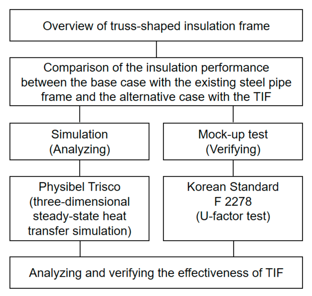
1.2. Methods and Procedures
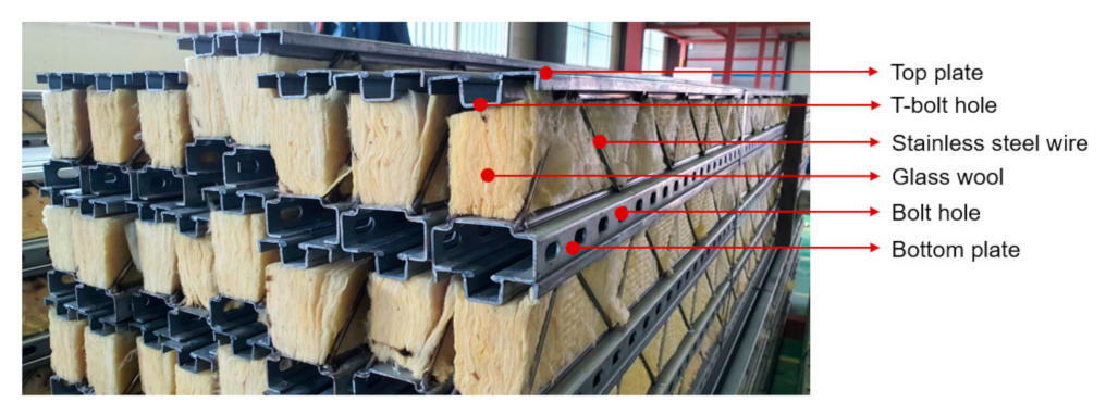
2. Overview of Truss-Shaped Insulation Frame
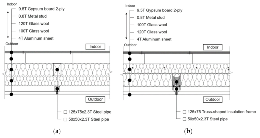
3. Setup of the Base Case and Alternative Case
4. Three-Dimensional Steady-State Heat Transfer Simulation
4.1. Overview of Simulation
4.1.1. Simulation Model
4.1.2. Simulation Method
4.1.3. Evaluation Indices of Insulation Performance
4.2. Simulation Results
5. Performance Verification through Mock-Up Test
5.1. Overview of Mock-Up Test
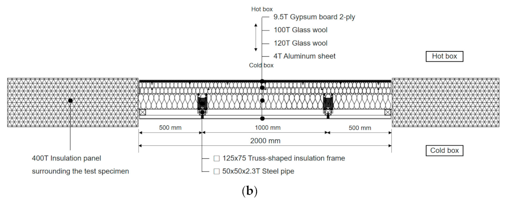
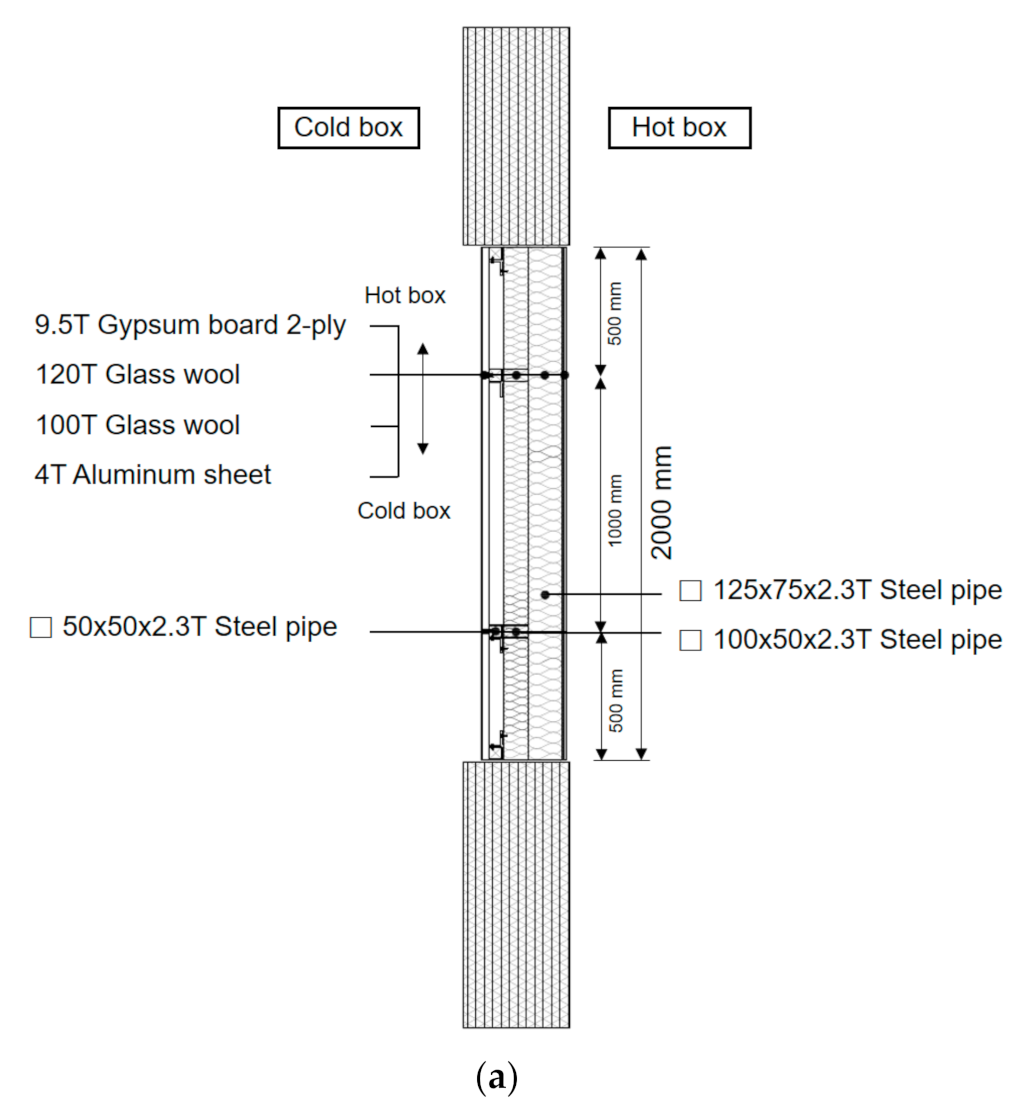
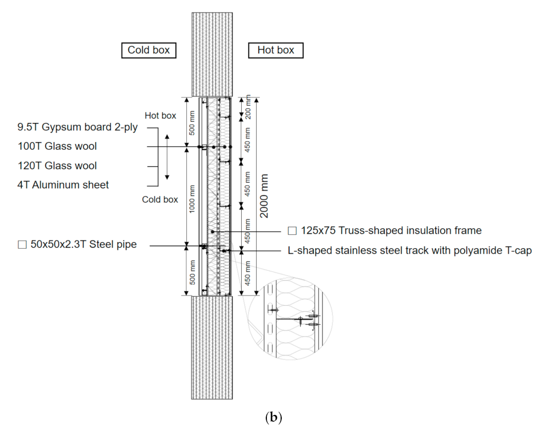
5.1.1. Mock-Up Model
5.1.2. Mock-Up Test Method
5.2. Mock-Up Test Results
6. Conclusions
- (1)
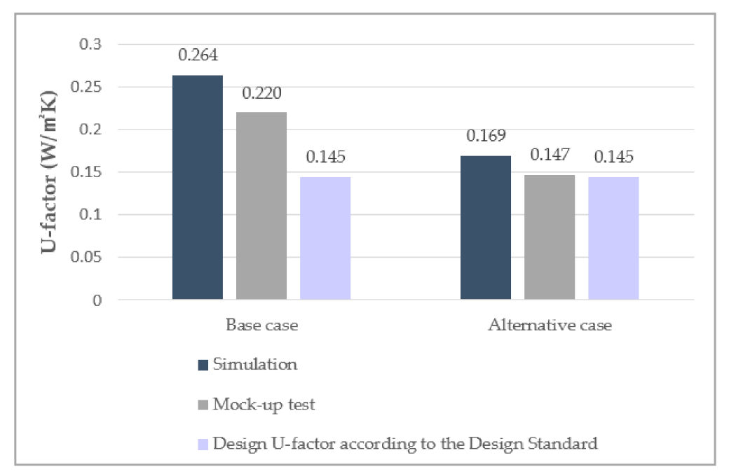
- The simulation results showed that the effective U-factor of the alternative case was 36% lower than that of the base case, indicating a significant reduction in heat loss by decreasing the thermal bridging effect. The lowest indoor surface temperature of the alternative case was 0.5 °C higher than that of the base case, showing that the surface condensation risk was also reduced.
- (2)
- In the mock-up test results, the U-factor of the alternative case was 33% lower than that of the base case in a similar to the degree of reduction of the effective U-factor in the simulation results, confirming the large heat loss reduction effect of the alternative case.
- (3)
- For the base case, both the effective U-factor by simulation and the U-factor by the mock-up test were much higher than the design U-factor according to the Design Standard, which does not consider the influence of the thermal bridge, indicating a significant increase in heat loss caused by the thermal bridge. For the alternative case, however, both were found to be similar to the design U-factor.
Author Contributions
Funding
Institutional Review Board Statement
Informed Consent Statement
Data Availability Statement
Acknowledgments
Conflicts of Interest
References
- Joint Ministries of Korean Government. Revision of the Basic Roadmap for Achieving the National Greenhouse Gas Reduction Target in 2030; Joint Ministries of Korean Government: Sejong, Korea, 2018.
- Ministry of Land, Infrastructure and Transport. Press Release, Zero Energy Building, Beyond Buildings to Cities; Korean Ministry of Land, Infrastructure and Transport: Sejong, Korea, 2019.
- Park, M.-J.; Song, J.-H.; Lim, J.-H.; Song, S.-Y. Analysis of needs for building envelope insulation regulations reflecting the thermal bridging effects through similar regulations review and case study. J. Archit. Inst. Korea Plan. Des. 2015, 31, 303–312. [Google Scholar] [CrossRef]
- Ministry of Land, Infrastructure and Transport. Design Standard for Energy-Efficient Buildings; Notification No. 2017-881; Korean Ministry of Land, Infrastructure and Transport: Sejong, Korea, 2017.
- Song, J.-H.; Lim, J.-H.; Song, S.-Y. Evaluation of alternatives for reducing thermal bridges in metal panel curtain wall systems. Energy Build. 2016, 127, 138–158. [Google Scholar] [CrossRef]
- Song, J.-H.; Park, M.-J.; Lim, J.-H.; Song, S.-Y. Energy, condensation risk and constructability evaluation of metal-exterior curtain wall panel systems for reducing heat loss through thermal bridges. J. Archit. Inst. Korea Plan. Des. 2015, 31, 283–293. [Google Scholar] [CrossRef]
- Kim, S.-S.; Yim, H.-C. Evaluation of the Thermal Transmittance of Curtain walls according to EN 13947. J. Archit. Inst. Korea Plan. Des. 2012, 28, 401–408. [Google Scholar]
- Song, J.-H.; Park, S.-H.; Park, M.-J.; Lim, J.-H.; Song, S.-Y. Influence of thermal bridges on the insulation performance of curtain wall panel systems. J. Asian Archit. Build. Eng. 2015, 14, 741–748. [Google Scholar] [CrossRef] [Green Version]
- Brent, G.; Elizabeth, F.; Mehrangiz, Y.; Dariush, A. The significance of bolts in the thermal performance of curtain-wall frames for glazed facades. In Proceedings of the ASHRAE Winter Meeting, San Francisco, CA, USA, 17–21 January 1998. [Google Scholar]
- Park, H.-Y.; Park, S.-J. A study on the thermal performance factors and effects of each part of curtain wall frame for development of curtain wall frame with thermal conductivity 1.0 W/m2K or less. J. Korean Inst. Archit. Sustain. Environ. Build. Syst. 2020, 14, 484–496. [Google Scholar]
- Theodoros, G.T.; Aikaterini, G.T.; Karolos, J.K.; Dimitrios, K.B. Thermal bridging analysis on cladding systems for building facades. Energy Build. 2015, 109, 377–384. [Google Scholar]
- Oh, J.-M.; Song, J.-H.; Lim, J.-H.; Song, S.-Y. Analysis of building energy savings potential for metal panel curtain wall building by deducing thermal bridges at joints between panels. Energy Procedia 2016, 96, 696–709. [Google Scholar] [CrossRef] [Green Version]
- Shin, D.-I. Development of thermal breaker for the dry envelope and applied case. In Proceedings of the Annual Conference of AIK 2017, Gyeongju, Korea, 25–27 October 2017. [Google Scholar]
- Song, J.-H.; Lee, D.-Y.; Shin, D.-I.; Jun, H.-D.; Park, C.-Y.; Kim, S.-K. Evaluation of building envelope Performance of a dry exterior insulation system using truss insulation frame. J. Archit. Inst. Korea Struct. Constr. 2019, 35, 153–164. [Google Scholar]
- Song, J.-H.; Park, C.-Y.; Jeong, J.-W. Energy performance evaluation for exterior insulation system consisting of truss-form wire-frame mullion filled with glass wool. Energies 2020, 13, 4486. [Google Scholar] [CrossRef]
- KS F 2278. Standard Test Method for Thermal Resistance for Windows and Doors; Korean Standard Association: Chungcheongbuk-do, Korea, 2017. [Google Scholar]
- Ministry of Land, Infrastructure and Transport. Enforcement Decree of the Building Act; Notification No. 31270; Korean Ministry of Land, Infrastructure and Transport: Sejong, Korea, 2021.
- ASHRAE Standard 90.1. Energy Standard for Buildings except Low-Rise Residential Buildings; American Society of Heating, Refrigerating and Air-Conditioning Engineers: New York, NY, USA, 2013. [Google Scholar]
- ISO 10211: 2017. Thermal Bridges in Building Construction—Heat Flows and Surface Temperatures—Detailed Calculations; International Standard Organization: Geneva, Switzerland, 2017. [Google Scholar]
- Physibel. TRISCO Manual of Version 14.0w; Physibel: Maldegem, Belgium, 2017; Available online: http://www.physibel.be (accessed on 7 May 2021).
- Korea Energy Agency. Guide to Design Standard for Energy-Efficient Buildings; Korea Energy Agency: Ulsan, Korea, 2020. [Google Scholar]
- ISO 10077-2: 2017. Thermal Performance of Window, Doors and Shutters—Calculation of Thermal Transmittance—Part2: Numerical Method for Frames; International Standard Organization: Geneva, Switzerland, 2017. [Google Scholar]
- Ministry of Land, Infrastructure and Transport. Design Standard for Preventing Condensation in Apartment Buildings; Notification No. 2016-835; Korean Ministry of Land, Infrastructure and Transport: Sejong, Korea, 2016.


| Boundary | Temperature (°C) | Surface Heat Transfer Coefficient (W/m2K) |
|---|---|---|
| Outdoor | −11.3 | 23.26 |
| Indoor | 20 | 9.09 |
| Material | Thermal Conductivity (W/mK) | Material | Thermal Conductivity (W/mK) |
|---|---|---|---|
| Concrete | 1.6 | Steel | 44 |
| Cement mortar | 1.4 | Galvanized steel | 53 |
| Gypsum board | 0.18 | Stainless steel | 15 |
| Glass wool | 0.034 | Polyamide | 0.25 |
| Mineral wool | 0.036 | Silicone sealant | 0.35 |
| Aluminum sheet | 200 | - | - |
| Performance Index | Base Case | Alternative Case | ||
|---|---|---|---|---|
Temperature distribution | 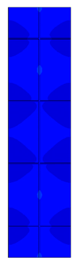 | 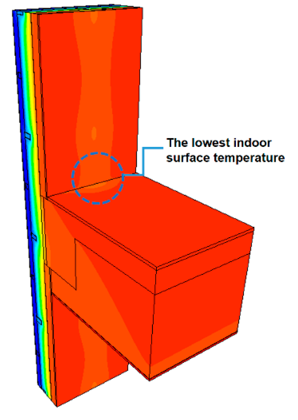 | 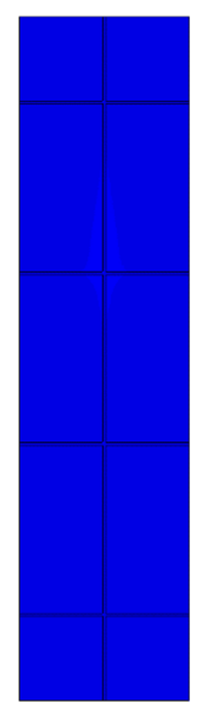 | 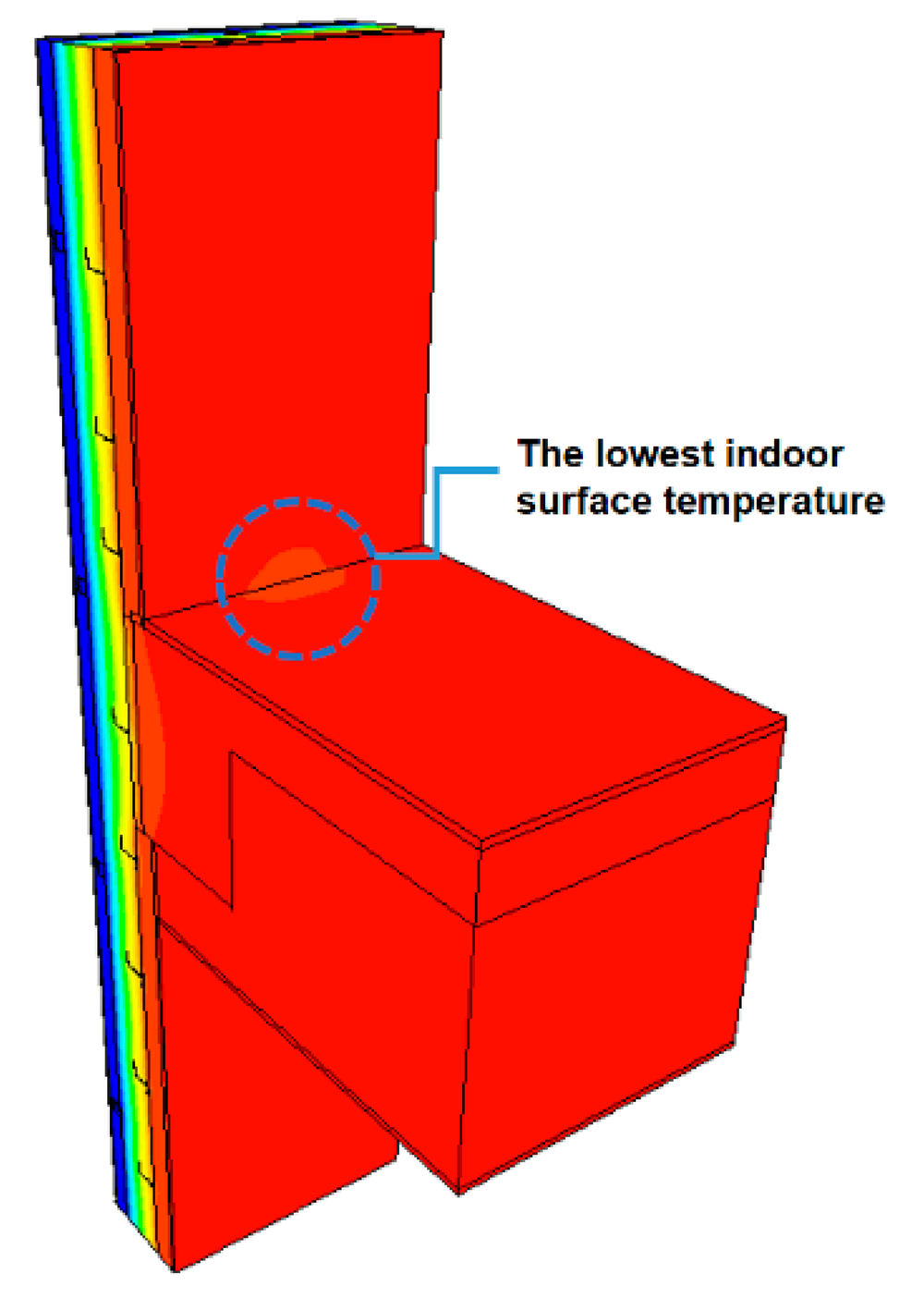 |
| Outdoor surface | Indoor surface | Outdoor surface | Indoor surface | |
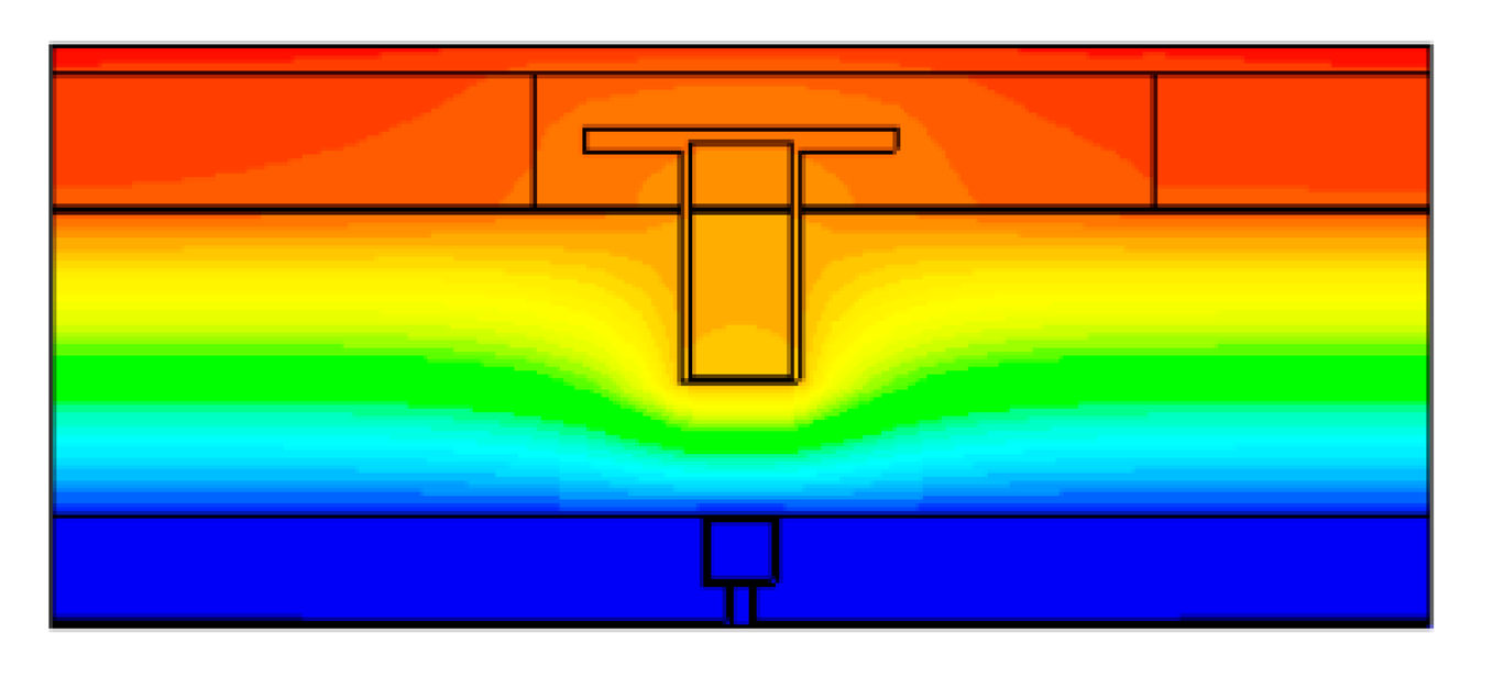 | 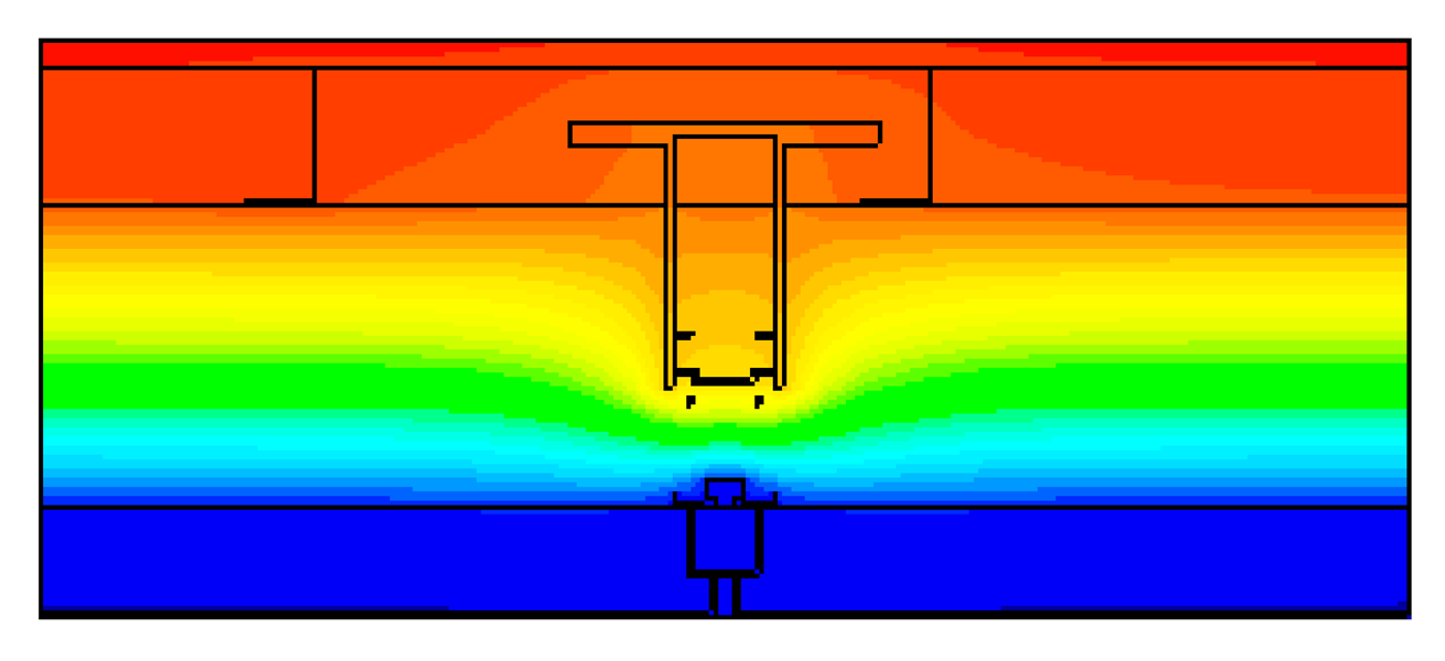 | |||
| Horizontal section (at metal fasteners) | Horizontal section (at metal fasteners) | |||
| q (W) | 33.1 | 21.1 | ||
| Ueff (W/m2K) | 0.264 | 0.169 | ||
| The lowest indoor surface temperature (°C) | 17.7 | 18.2 | ||
| TDR | 0.07 | 0.05 | ||
| Boundary | Temperature (°C) | Surface Thermal Resistance (m2K/W) |
|---|---|---|
| Cold box | 0 ± 1.0 | 0.05 ± 0.02 |
| Hot box | 20.0 ± 1.0 | 0.11 ± 0.02 |
Publisher’s Note: MDPI stays neutral with regard to jurisdictional claims in published maps and institutional affiliations. |
© 2021 by the authors. Licensee MDPI, Basel, Switzerland. This article is an open access article distributed under the terms and conditions of the Creative Commons Attribution (CC BY) license (https://creativecommons.org/licenses/by/4.0/).
Share and Cite
Choi, B.-H.; Song, S.-Y. Insulation Performance Comparison of Curtain Wall Systems with Existing Pipe Frames and Truss-Shaped Insulation Frames. Energies 2021, 14, 4682. https://doi.org/10.3390/en14154682
Choi B-H, Song S-Y. Insulation Performance Comparison of Curtain Wall Systems with Existing Pipe Frames and Truss-Shaped Insulation Frames. Energies. 2021; 14(15):4682. https://doi.org/10.3390/en14154682
Chicago/Turabian StyleChoi, Bo-Hye, and Seung-Yeong Song. 2021. "Insulation Performance Comparison of Curtain Wall Systems with Existing Pipe Frames and Truss-Shaped Insulation Frames" Energies 14, no. 15: 4682. https://doi.org/10.3390/en14154682
APA StyleChoi, B.-H., & Song, S.-Y. (2021). Insulation Performance Comparison of Curtain Wall Systems with Existing Pipe Frames and Truss-Shaped Insulation Frames. Energies, 14(15), 4682. https://doi.org/10.3390/en14154682