Article

Parking Pose Generation for Autonomous Freight Collection by Pallet Handling Car-like Robot

1
PMAR Robotics, DIME, University of Genova, 16126 Genova, Italy
2
LS2N, CNRS, Ecole Centrale de Nantes, 1 Rue de la Noë, 44300 Nantes, France
*
Author to whom correspondence should be addressed.
Current address: Room 213, LS2N, CNRS, Ecole Centrale de Nantes, 1 Rue de la Noë, 44300 Nantes, France.
Energies 2021, 14(15), 4677; https://doi.org/10.3390/en14154677
Submission received: 5 July 2021 / Revised: 29 July 2021 / Accepted: 30 July 2021 / Published: 1 August 2021
(This article belongs to the Special Issue Vehicle and Traffic Safety)

Abstract

:
This paper focuses on autonomous navigation for an electric freight vehicle designed to collect freight autonomously using pallet handling robots installed in the vehicle. Apart from autonomous vehicle navigation, the primary hurdle for vehicle autonomy is the autonomous collection of freight irrespective of freight orientation/location. This research focuses on generating parking pose for the vehicle irrespective of the orientation of freight for its autonomous collection. Freight orientation is calculated by capturing the freight through onboard sensors. Afterward, this information creates a parking pose using mathematical equations and knowledge of the vehicle and freight collection limitations. Separate parking spots are generated for separate loading bays of the vehicle depending on the availability of the loading bay. Finally, results are captured and verified for different orientations of freight to conclude the research.

1. Introduction

Vehicle FURBOT (Freight Urban RoBOTic vehicle) is a complete drive-by-wire electric freight vehicle designed to operate in last-mile delivery operations in an urban environment. The vehicle was part of the European Green Vehicles Initiative (EGVI) funded under the umbrella of the FP7-Transport European project ending in December 2015 [1,2]. The vehicle was completed as an entire drive-by-wire vehicle with the possibility of being upgraded to an autonomous vehicle. Currently, the project is being developed to convert it from a drive-by-wire to a completely autonomous vehicle. Thus, the necessity of autonomous freight collection is generated.
For autonomous vehicle navigation, a mathematical model has been built for performance evaluation of the vehicle [3] which is later used for developing sensor-based strategies for obstacle avoidance [4]. Further automation is achieved by controlling the pallet handling robot using hydraulic pressure-flow rate control [5]. Strategies are built to convert the vehicle from drive-by-wire to a completely autonomous vehicle [6]. Additionally, work on perception and control strategies for autonomous docking of the freight has also been previously studied [7]. This work is the next step in attaining the automation of the vehicle for it to auto-load its freight.
FURBOT has to take part in SHOW (SHared automation Operating models for Worldwide adoption) project where it is required to deliver freight autonomously to customers across an urban area. Currently, the vehicle is not equipped with proper algorithms for the autonomous collection of freight. However, the vehicle will be equipped with autonomous navigation software, which has its own autonomous parking algorithms [8,9]. The autonomous freight collection requires the vehicle to park next to the freight, such that it can collect freight autonomously. For that, a need for generation of correct parking pose is required so the already available parking algorithms can maneuver the vehicle to the correct parking pose. Thus, the need for our work.
The role of autonomous vehicles in an urban environment is still being studied, and there is a gap in understanding the role of urban autonomous vehicles in smart urban mobility [10]. Autonomous freight delivery and their adoption in society are in preliminary stages, and surveys are being conducted for their acceptability in the society [11]. Further studies are being conducted to understand the role of autonomous vehicles in logistics [12]. Still, the concept of using manned deliveries for last-mile delivery through autonomous vehicles is being studied [13]. Privately-owned autonomous vehicles not designed for freight delivery are being looked into, and their potential is being discussed [14]. Currently, autonomous freight delivery through a designated autonomous freight vehicle is still a new subject, and the latest research proves that the solution for autonomous freight delivery is yet to be explored.
Freight delivery in an urban environment comes with many predefined constraints, e.g., loading constraints, vehicle routing problems [15] or compartment and order fulfillment related issues [16]. Many types of loading constraints and vehicle routing problems are discussed in [15,17]. Vehicle compartment issues are further divided into the flexibility of compartment sizes, assignment of product types, and share-ability of compartments. In contrast, order fulfillment issues comprise the mode of demand fulfillment and the total number of visits per customer [16]. However, all these logistic issues do not deal with how the freight needs to be loaded in the vehicle, especially dealing with the freight loading autonomously.
The generation of a parking spot for autonomous vehicles has also been studied in-depth in the last decade. Many next-generation vehicles are already equipped with autonomous parking [18]. New research in parking solutions varies in finding niche problems within the vehicle parking solution domain, including vision-based indoor parking [19], parking of fleet of vehicles [20], collision-avoidance-based parking [21] and sensor (Lidar)-based parking solutions [22]. However, it is challenging to find parking solutions for freight vehicles, especially for freight loading. The closest work on autonomous parking for articulate vehicles is studied in [23], but it is still insufficient in resolving freight-based parking solutions. As FURBOT is a designated freight handling vehicle, the parking solution for autonomous loading of freight needs to be resolved.
Path generation and detecting correct parking pose for the vehicle are interesting subjects, especially in autonomous vehicles as they need to park by themselves. Usual work on vehicle parking pose estimation comes from parking pose marking recognition [24] or using a camera to detect these markings [25]. Apart from parking pose recognition from sensor feedback, estimation of parking pose requires solving geometrical equations for path generation or calculating current parking pose [26,27]. This research also exploits geometrical equations after freight detection to generate a parking pose that can solve the autonomous freight collection problem.
Electric freight vehicle poses a unique challenge for the creation of parking pose concerning freight for its collection. As it is not possible to make the freight perfectly align with any known orientation before loading the freight. Furthermore, there is a hassle for aligning freight to an orientation each time before loading the freight, even if a solution exists. It is much easier to consider autonomously loading the freight through aligning the vehicle w.r.t the freight. However, previous research in this domain is not available, i.e., the generation of parking pose for a freight handling vehicle for freight collection. Furthermore, the vehicle FURBOT is unique because it loads the freight sideways within itself through its loading bays, unlike typical forklift trucks.
This research is a step towards an autonomous collection of freight for the vehicle, especially the part of creating autonomous parking pose w.r.t freight keeping in line the constraints posed by vehicle FURBOT. Currently, there is no alternative solution for collecting freight autonomously for such vehicles. The ability to create a parking pose w.r.t an inanimate object, which is subject to change its orientation and position, is not previously studied and discussed, thus the need of this research. The highlight of this research is creating a parking pose for such a vehicle, keeping in mind the constraints posed by the freight and the vehicle. Finally, testing the results to validate the proposed mathematical modeling for the solution to the unique problem.
In the next section, we discuss the problem and approach to the parallel freight parking issue, discussing the issues concerning freight detection, how the vehicle should be oriented for collection of the freight, and how parking spot should be defined w.r.t freight. Following, in Section 3, the software and control architecture of the vehicle is discussed, focusing on desired parking pose for the collection of freight. In Section 4, a mathematical model for vehicle parking pose is discussed. This section also covers the vehicle kinematic model and mathematical equations and notations for creating the parking pose for each loading bay of the vehicle. Section 5 elaborates on the desired results achieved of the parking pose for each loading bay of the vehicle, and the results are further verified for different freight poses, and the parking pose is validated as per requirement. Finally, in Section 6, the conclusions of the research are discussed.

2. Problem and Approach

The considered vehicle has to park, keeping the freight on the vehicle’s right-hand side for loading the freight through the designed loading bays. There are three core steps in defining the parking spot for the vehicle for the autonomous collection of freight. The critical issues in defining the parking spot are freight detection, the vehicle’s orientation, and defining parking spot reference to freight. These issues are further elaborated in their sub-sections below.

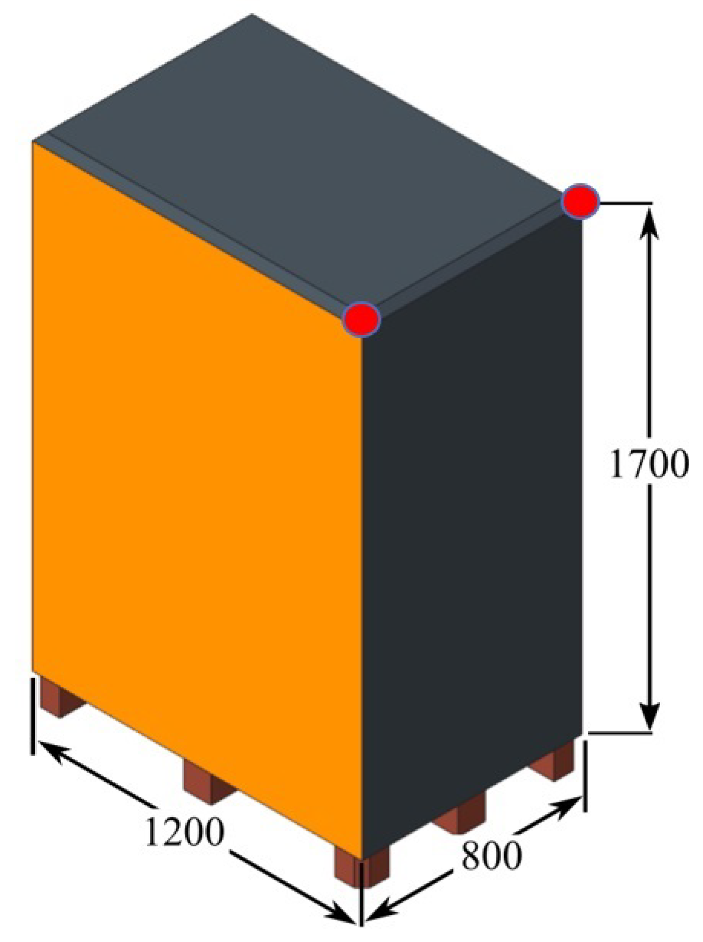
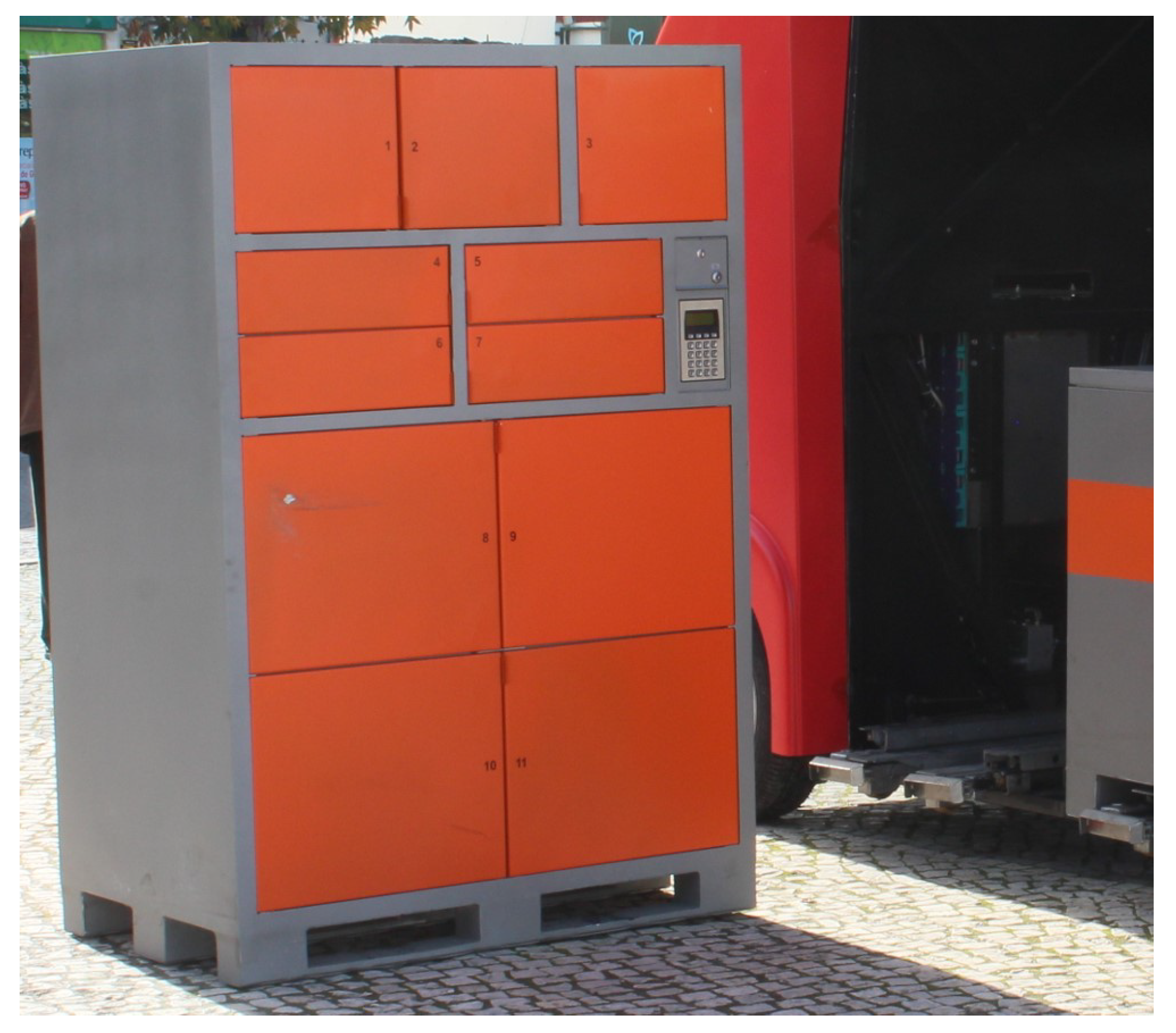
2.1. Freight Detection

The first step in defining the parking spot for the vehicle for loading freight autonomously is the detection of freight location. The freight vehicle is equipped with 3D LIDAR, which can identify and distinguish freight from the environment as the freight has a unique shape, size and color from the usual environment. Image feedback from an on-board camera is also used to distinguish freight from the environment. The design and dimensions of the vehicle freight box are given in Figure 1 (dimensions in mm), which also show the freight edges (highlighted in red) that need to be captured for correctly identifying the parking spot next to freight. Further dimensions for the freight box are available in [28].
The vehicle can load two freight boxes simultaneously, and because of the dimensions of the freight, it loads the freight from the depth edge of the freight (measuring 800 mm, as seen in Figure 1), as shown in Figure 2.

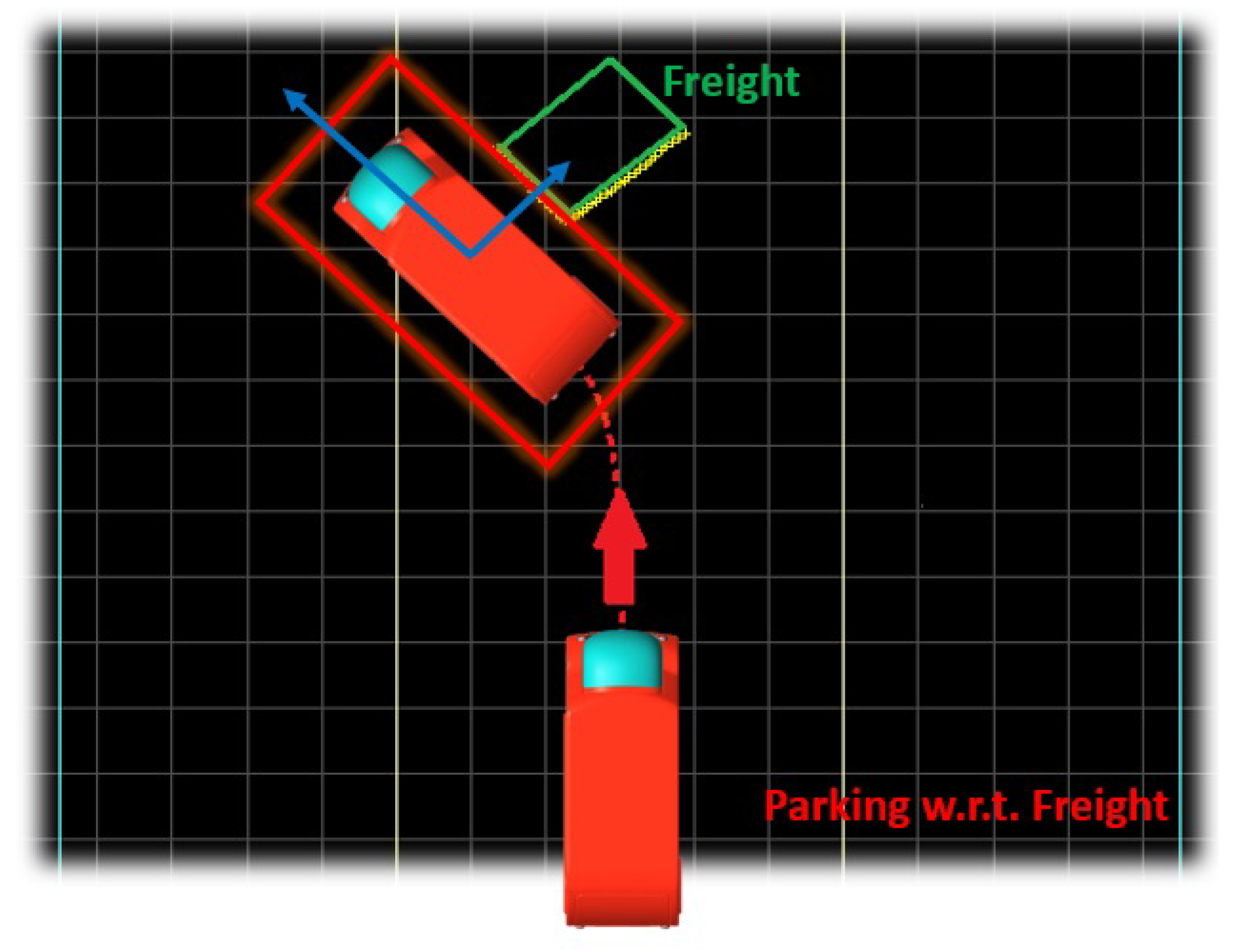
2.2. Orientation of Vehicle

The next consideration for loading is to park the vehicle next to the freight in such a manner that the vehicle’s right side is facing the freight, as shown in Figure 3, since the loading mechanism can only operate from the right-hand side of the vehicle. The maximum tolerance for collection of freight between the freight and vehicle is 300 mm [29]. This limitation, along with the width of the vehicle, defines our parking spot’s total width.
Furthermore, the vehicle is equipped with two separate loading bays, as shown in Figure 4. The freight has to be loaded in the vacant loading bay, i.e., if bay 1 is occupied, then load the freight in bay 2. As the loading bays are not centrally aligned with the freight, the vehicle has to adjust its parking spot accordingly so that the freight can be loaded in the available loading bay. Furthermore, the freight also needs to be aligned with the center of the forklift of the loading bays (as shown in Figure 4) for the forklifts to be inserted into the freight pallet.

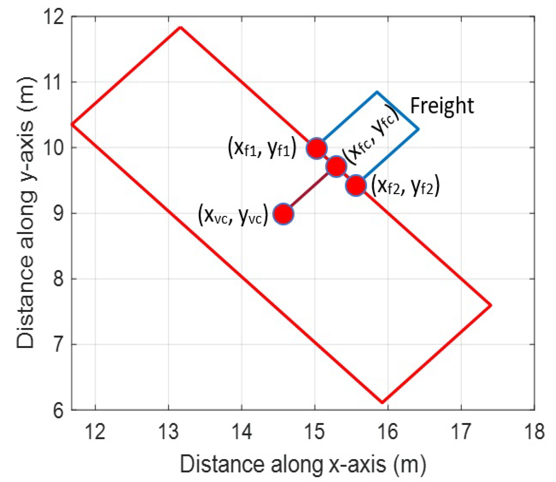
2.3. Defining Parking Spot Reference to Freight

The vehicle dimensions are given in Table 1. The width of the vehicle plus the tolerance to the freight defines the width of the parking space. To maintain a reasonable amount of parking maneuvers (≤3 for typical cases) [30], the length of the parking space is chosen to be 2 m more than the length of the vehicle.
Taking the loading of the freight and vehicle dimensions into consideration, the overall parking spot defined for the vehicle is a box of 2.1 × 6.0 m, as shown in Figure 3.

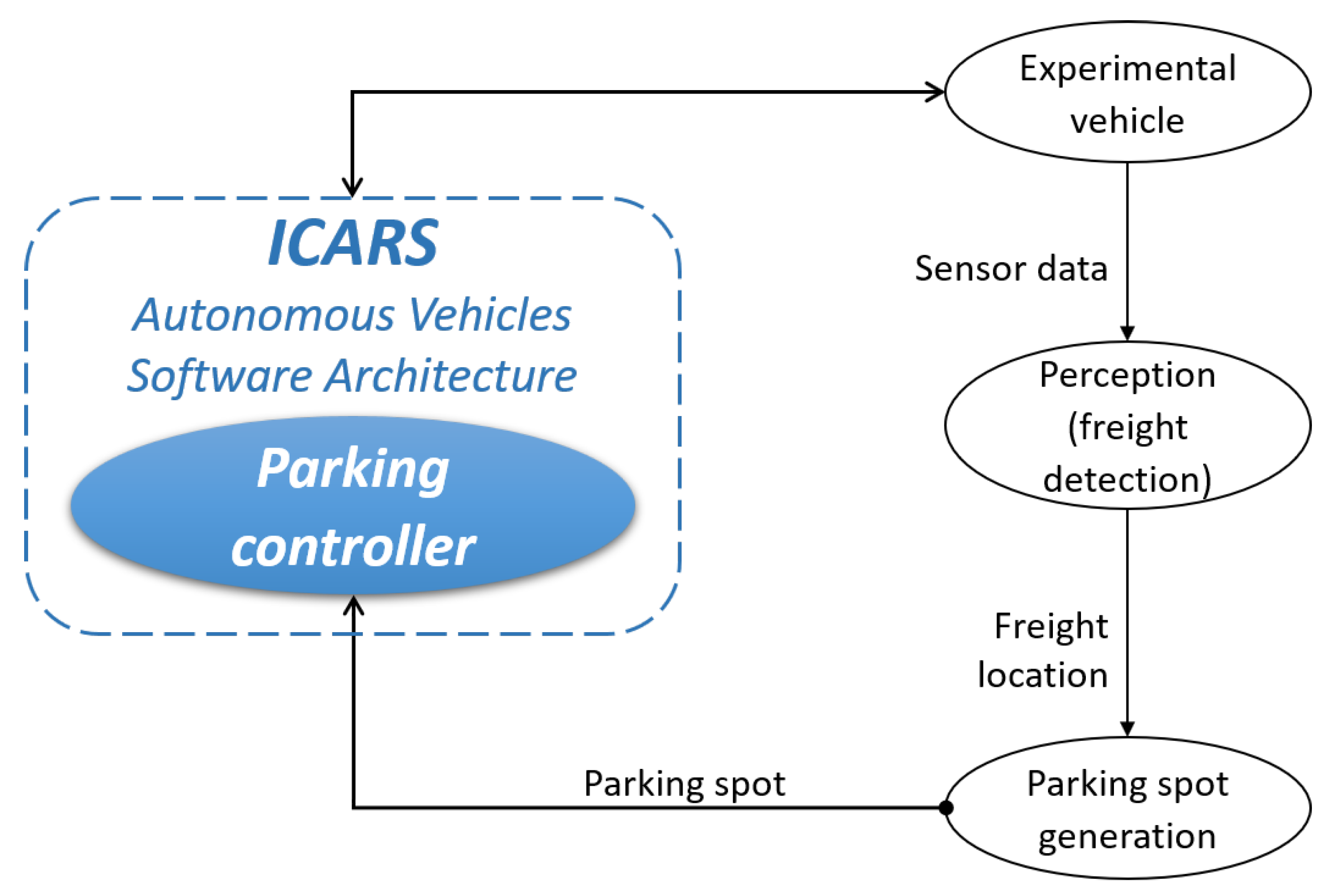
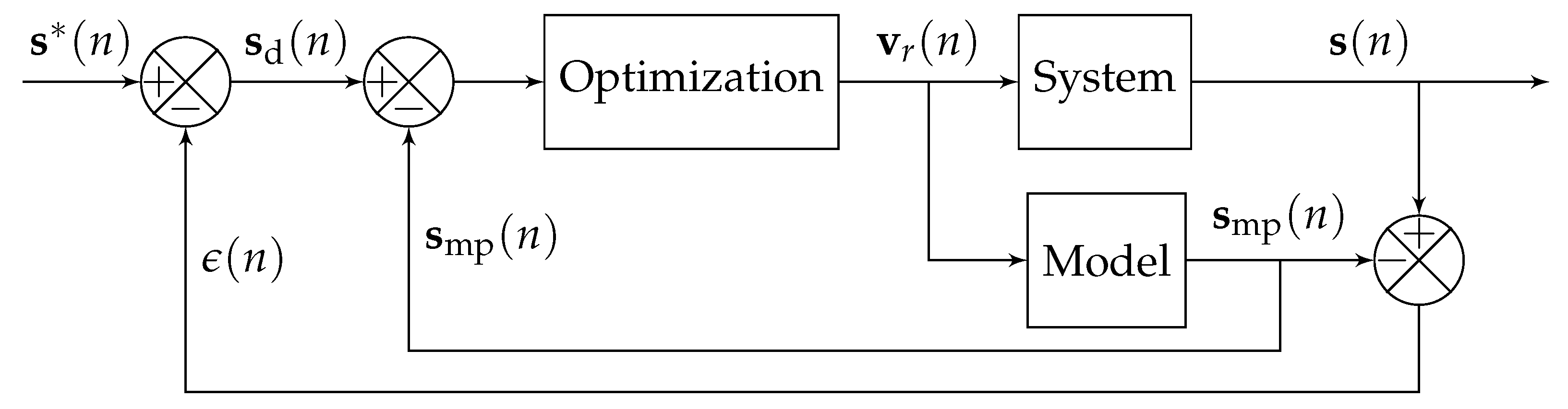
3. Software and Control Architecture

To speed up the development and integration process with the real experimental vehicle, Robot Operating System (ROS)-based autonomous vehicle’s software architecture (called ICARS (Software being developed at LS2N (Laboratoire des Sciences du Numérique de Nantes) www.ls2n.fr (accessed on 15 July 2021)) will be exploited (Figure 5). Considering the task to be accomplished, a particular interest is placed on the Multi-Sensor-Based Predictive Controller (MSBPC) used for parking [31]. As the name of the approach suggests, the parking controller is based on a combination of Model Predictive Control (MPC) and Multi-Sensor-Based Control in order to perform safe (collision-free) parking operations that rely solely on locally perceived sensor features signals and without needing to explicitly plan any path. Moreover, since the technique exploits locally perceived sensor features at each time instant, no localization system is inherently required. The MSBPC approach is now recalled.
An internal-model-control (IMC) structure [32] is used as a basis for formalizing the MSBPC approach (Figure 6). The robotized vehicle and perception system compose the System block. The input to this block is the control variable v r = [ v , δ ] T , where the longitudinal velocity is denoted by v and the steering angle by δ , while its output is the current value of the sensor features (i.e., corners of the parking spot). The reference signal s * is the desired value of the output s . General discrepancies between the current sensor features and the values that were predicted from the model (e.g., modeling errors and disturbances) are represented by the error signal ϵ :
ϵ ( n ) = s ( n ) s mp ( n )
where n denotes the current time.
The difference between the desired value s d and the predicted model output s mp is minimized by an optimization algorithm. Following Figure 6:
s d ( n ) = s * ( n ) ϵ ( n ) = s * ( n ) ( s ( n ) s mp ( n ) ) ,
from where one can deduce
s d ( n ) s mp ( n ) = s * ( n ) s ( n ) ,
thus, to track s * by s is equivalent to track s d by s mp .
The interaction model described in [31] is used in order to predict the evolution of the sensor features s mp over a finite horizon N p . The cost function is to be minimized with respect to a control sequence v ˜ r over N p and depends mainly on the difference between s d and s mp . As with any classical Model Predictive Control technique, only the first element v r ( n ) of the optimal control sequence is applied to the system at each iteration.
The controller (implemented in C++) runs online at 10 Hz using the solver NLopt [33] with a Sequential Least Squares Programming (SLSQP) algorithm [34]. Furthermore, it is assumed that both the vehicle’s longitudinal velocity and steering angle are controllable; thus, lower-level controllers that directly interface with the actuators are out of the scope of the parking approach.
The simulation inputs are four points generated based on a parked pose and the type of parking spot. This information is then transferred as a topic to the control node, which, in turn, generates a control command as a topic as well. The complete software is constructed in a manner that it is agnostic; it is working in a simulation environment or in a real vehicle.
Therefore, with the experimental vehicle being interfaced with ICARS, two additional ROS nodes would have to be developed: A perception one to extract the freight’s pose from sensory data and another one to generate a parking spot next to the freight. Once the parking spot has been successfully generated from the sensory data, the four corners that define it would have to be sent to the ICARS parking controller to park the vehicle in the desired pose to pick up the freight.

4. Mathematical Modeling and Notation

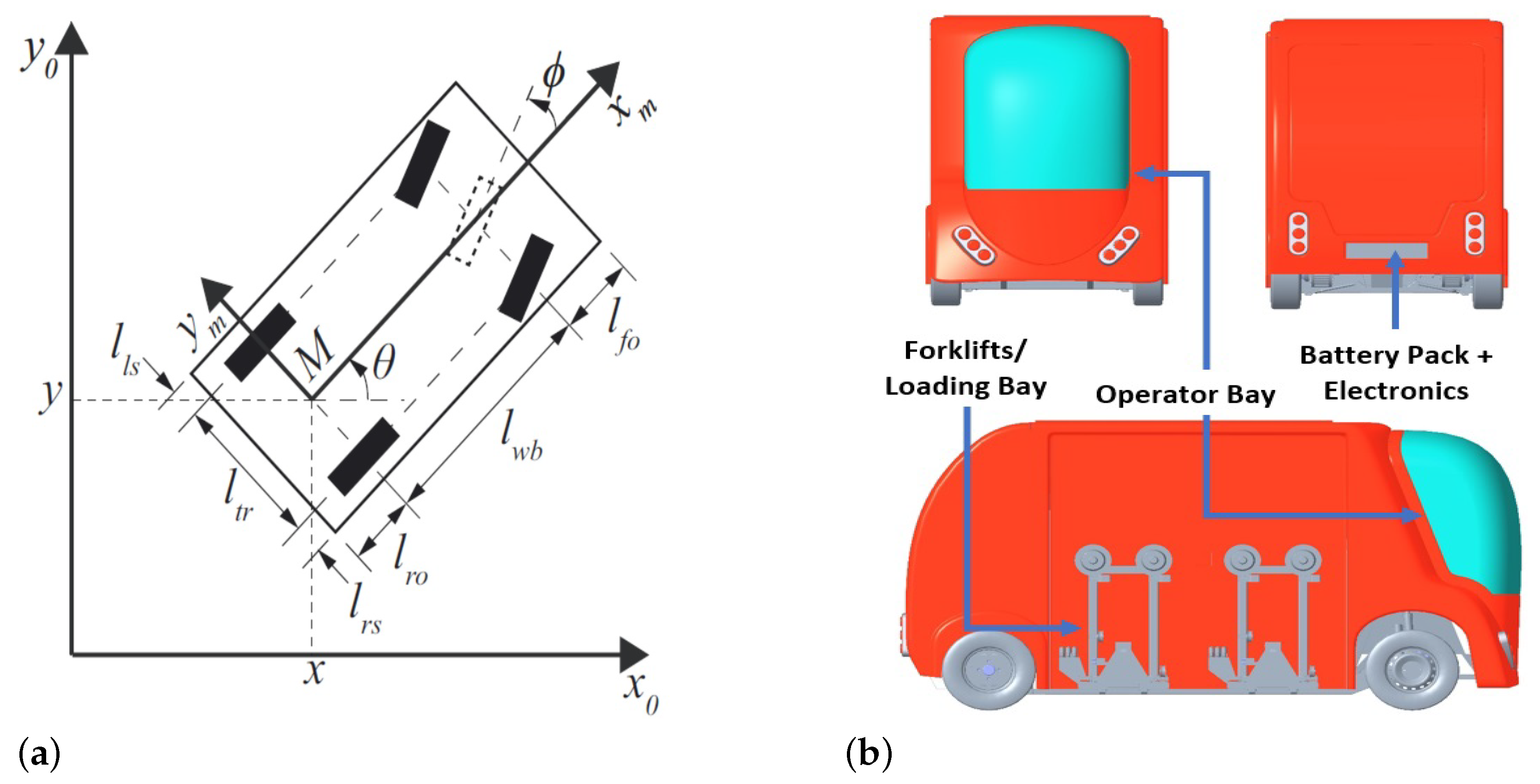
4.1. Vehicle Kinematic Model

The vehicle kinematic model for a rear-wheel driven vehicle as taken from [8] is presented by Equation (4). The freight vehicle also follows the same kinematic model for its drive.
x ˙ y ˙ θ ˙ ϕ ˙ = cos θ sin θ tan ϕ / l w b 0 v + 0 0 0 1 ϕ ˙
where v and ϕ ˙ are longitudinal and steering velocities. Since parking maneuvers are performed at low speed, one can consider the kinematic model as accurate enough. Further notations and elaboration of the model as given by Equation (4) are represented in Figure 7a. The vehicle used for parking evaluation is further represented in Figure 7b. There is a designated space for the vehicle operator, as shown in the figure. The battery pack and electronics bay holds the complete electronics for the operation of the vehicle.

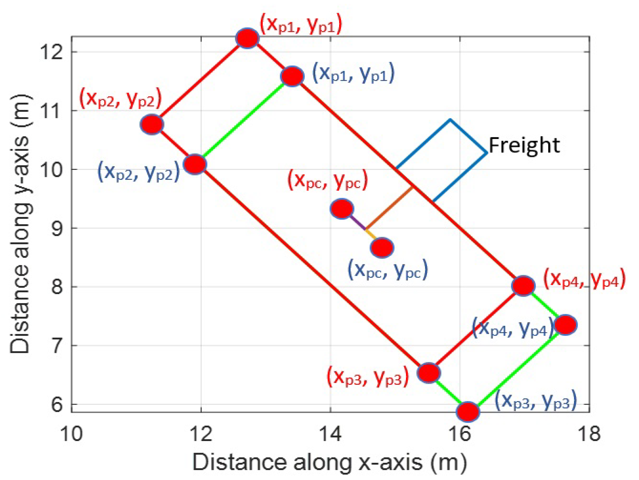
4.2. Points Acquisition for Parking Spot

For correctly identifying parking spots for the vehicle, the acquisition of the freight corners (highlighted by red), as shown in Figure 1, is required through sensor feedback. From there, using these points, the freight center point is calculated using Equation (5).
x f c = ( x f 1 + x f 2 ) 2 , y f c = ( y f 1 + y f 2 ) 2
Furthermore, knowledge from these two corner points is also used to calculate the inclination angle θ f of the freight using the Pythagoras theorem (Equation (6)).
θ f = tan 1 ( y f 2 y f 1 x f 2 x f 1 )
Using the width of the parking spot d w and information of the freight center point, the vehicle center point is calculated from the freight using Equation (7).
x v c = x f c + d w 2 cos ( θ f + 3 π 2 ) , y v c = y f c + d w 2 sin ( θ f + 3 π 2 )
The above-mentioned points are further explained in Figure 8. Using these points, freight collection parking spots are calculated. This is further explained in the next subsection.

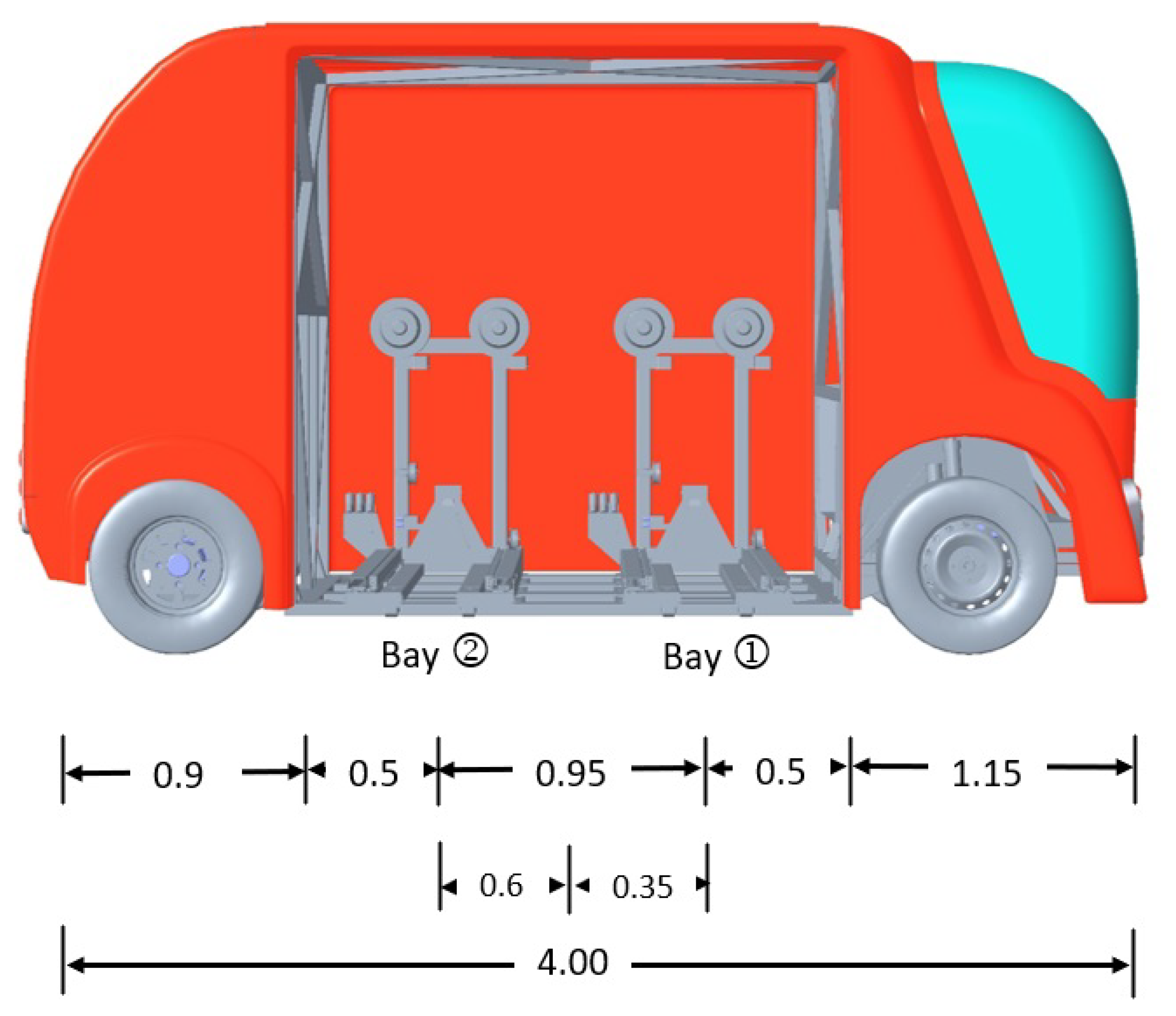
4.3. Parking Area with Respect to Loading Bays

As the vehicle is equipped with two loading bays, the parking spot w.r.t each loading bay is different. To load the cargo in the front-loading bay, the vehicle needs to park a certain distance behind its center point, as shown in Figure 4. If the first loading bay is occupied by the previously loaded freight, then the vehicle needs to park a little ahead of its center point by a distance so that the forks are perfectly aligned with the freight to load the freight in the second loading bay. The center point of the parking spot thus varies depending upon the availability of the loading bay. This is further explained in Equation (8).
x p c = x v c + d b 1 cos θ f , x v c d b 2 cos θ f ,   , y p c = y v c + d b 1 sin θ f , if bay   1 = 1 y v c d b 2 sin θ f , otherwise
where d b 1 and d b 2 are the positive distances of loading bay 1 and 2 from vehicle center (measurement shown in Figure 4), and ( x v c , y v c ) is the center-point of parking spot. The condition bay   1 = 1 denotes the condition of availability of loading bay 1. If bay 1 is available to load the freight, then the first condition applies or else the parking spot is generated w.r.t second loading bay.
After defining the center of the parking spot, the four corners of the parking spot can be defined through Equations (9)–(12) using the knowledge of parking width ( d w ), parking length ( d l ), angle of the freight ( θ f ) and parking center-point ( x p c , y p c ) . The collection of the first corner of the parking pose requires the knowledge of parking pose width + length. The derivation of equations is based on trigonometric relations and point transformation from the known parking center-point to the first edge of the parking pose. Since all four lines of the parking pose are parallel or perpendicular to the freight, the solution is formed by adding the respective angle ( 90 , 180 , 270 ) to the angle of the freight θ f for calculation of next point of the parking pose.
x p 1 = x p c + d w 2 cos ( θ f + π 2 ) + d l 2 cos ( θ f + π ) , y p 1 = y p c + d w 2 sin ( θ f + π 2 ) + d l 2 sin ( θ f + π )
x p 2 = x p 1 + d w cos ( θ f + 3 π 2 ) , y p 2 = y p 1 + d w sin ( θ f + 3 π 2 )
x p 3 = x p 2 + d l cos ( θ f ) , y p 3 = y p 2 + d l sin ( θ f )
x p 4 = x p 3 + d w cos ( θ f + π 2 ) , y p 4 = y p 3 + d w sin ( θ f + π 2 )
The four corners of the parking pose ( x p 1 , y p 1 ) ,   ( x p 2 , y p 2 ) ,   ( x p 3 , y p 3 ) and ( x p 4 , y p 4 ) are the consequent four corners of the parking pose. These points are further explained later.
The summary of the whole pose generation solution is as follows. The vehicle is required to detect freight and acquire the corner points of the freight from the side where it can be loaded. Afterwards, Equation (5)–(12) are solved to get the correct pose for loading freight into the vehicle. The complete process of correct pose generation is further summarized in the flowchart presented in Figure 9.

5. Results

By using the mathematical equations and notations discussed in the previous section, the node for the vehicle parking spot was run and tested to verify if the parking spot is generated according to the loading bays. The results are further discussed in the sections below for further clarity.

5.1. Parking Spot Definitions w.r.t Loading Bays

The results are first validated for generating the respective parking spot for front and rear loading bays. Figure 10 shows the output of parking pose generated for randomly positioned freight at a 45 degree angle. The blue-colored text represents the points for the parking spot definition concerning the front loading bay, whereas the red-colored text represents the parking spot concerning the rear loading bay. The red line from the parking spot center towards freight represents the right-hand side of the vehicle, thus specifying the heading of the vehicle.
From Figure 10, we can observe that the vehicle parks behind the center-point of the vehicle for loading freight in the first loading bay, whereas it parks a little ahead of its center-point when it is loading freight in the second loading bay. Furthermore, points 1 and 2 show the front end of the parking pose, and points 3 and 4 show the rear end of the pose generated. These results are also in coherence with the physical vehicle anatomy and the mathematical methodology proposed, henceforth validating our results.

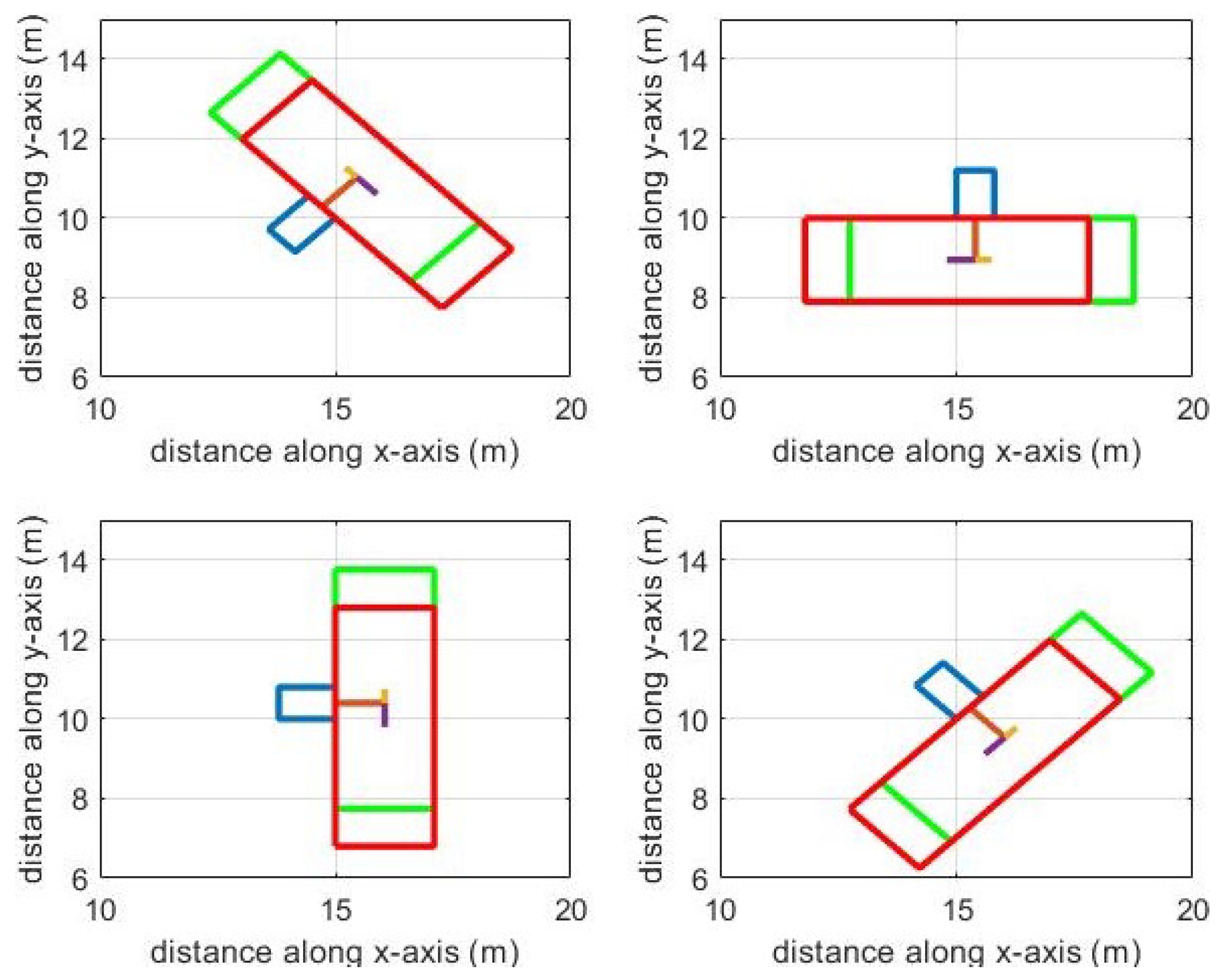
5.2. Results for Different Freight Placement

As it is not possible to make sure that the orientation of freight is perfectly aligned with any pre-determined reference, the parking spot for the vehicle must be generated automatically, keeping in view the orientation of the freight. This conditional issue has been taken into consideration prior in the mathematical modeling of the parking spot. The code generated is validated for different orientations of the freight (Figure 11) to verify that the correct parking spot is generated irrespective of the orientation of the freight.
The results achieved, as shown in Figure 11, show four different orientations of freight (225, 0, 90 and 135 degrees, respectively) and the respective parking spot generated for each loading bay. The results show that irrespective of the orientation of the freight, the parking spot is generated accordingly for the vehicle for collecting the freight for the available loading bay.
Furthermore, the results presented also validate our purpose of generating parking pose autonomously irrespective of the orientation of the freight. The results also show that the vehicle will always park against the freight keeping the freight on the right-hand side of the vehicle so that it can be loaded in the available loading bay, i.e., the heading of the vehicle and loading bay location is always kept into consideration during the autonomous generation of a parking pose. The consideration of the freight w.r.t vehicle is shown by the red line generated from the center of the pose towards the freight (as shown in the figure with the red line). This allows the vehicle to know the direction of the parking pose and the heading angle for the vehicle. The parking pose points generated with the help of Equations (9)–(12) lets the vehicle know the heading of the vehicle as well. Point 1 and 2 depict the points where the front of the vehicle should face, and point 3 and 4 depict the points for the rear end of the vehicle.

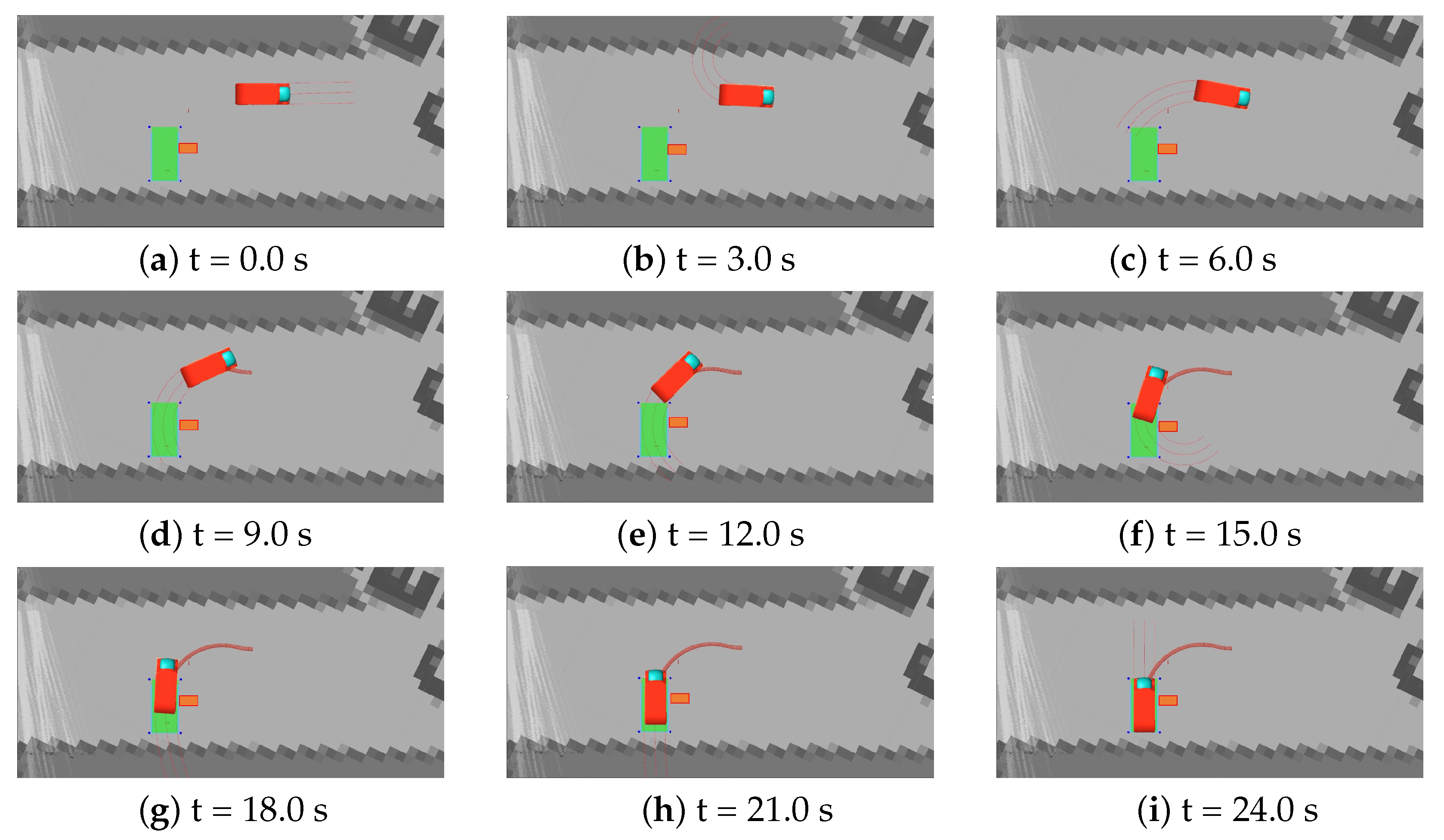
5.3. Vehicle Parking in ROS Environment

As discussed earlier in Section 3, ROS environment-based software architecture ICARS is exploited to speed up the actual experiments. Using the already developed parking schemes within the software architecture [8,9,31], we can park the vehicle in the designated parking pose. The already built parking algorithms are sufficient for maneuvering the vehicle within the parking pose generated autonomously for the freight collection. Figure 12 shows the time-wise parking maneuver for vehicle FURBOT in the parking pose generated for the freight. Due to the constraint environment, the vehicle cannot park after detecting the freight because it needs to fulfill the requirement to park the vehicle, keeping the right side of the vehicle towards the freight. Thus, the vehicle has to move ahead of the freight and park while reversing, as shown in Figure 12. These results are generated in ICARS software architecture with input from the simulated sensors mounted on the vehicle.
In Figure 12, the orange box depicts the freight placement and location. The green rectangle represents the parking pose generated w.r.t freight. The red trail left behind the vehicle denotes the performed parking maneuver, and the red lines in front or at the back of the vehicle depict the direction and steering angle of the vehicle.
The virtual experiment is performed in the already installed maps of ICARS software architecture. The environment is constrained by natural buildings surrounding the area. Furthermore, the parking algorithm can detect and avoid obstacles, e.g., pedestrians, in case the vehicle can detect them [31]. The results validated in the ICARS environment prove that the methodology behind generating such parking pose for autonomous freight collection is valid and resolves the issue for autonomous parking pose generation w.r.t freight.

6. Conclusions and Perspectives

Research perspectives for this research were to highlight the gap between currently available research and how to resolve autonomous parking for freight collection. For addressing this issue, collecting the orientation and freight location are key values for the proposed algorithm. Using these key values, we can identify the parking pose for the vehicle for it to load the freight autonomously.
Major findings of this research discuss and resolve the issue related to parking the vehicle next to the freight for loading it into the vehicle. The hurdle of generating a parking spot that could lead to the successful loading of freight is looked into. Control architecture and vehicle dynamics were previously built and checked against different parking conditions, i.e., perpendicular, parallel and angled parking. This enabled the research to focus on the parking pose of the vehicle for freight collection. The solution required an algorithm that can define parking pose for our unique problem of loading the freight autonomously. With this research, this issue is resolved.
Concerning the correct pose for autonomous loading in respective bays of the vehicle, detection of freight from the surroundings is required. Once localization of freight is attained, then the proposed mathematical model suffices to generate the correct parking pose for the vehicle. However, the detection of freight and its localization is out of the scope of this research and will be looked into our future work. The parking pose length and width are defined, keeping minimal maneuvers required and distance to freight into consideration.
Considerations are kept for loading the freight in the correct loading bay. Separate parking spots are generated depending upon which loading bay is to be used for loading the freight into the vehicle. Simulating the freight with different orientations and generating the parking spot accordingly is also verified. The mathematical model verifies that if the freight is correctly identified from the environment, the parking spot generated will be correct irrespective of the orientation or location of the freight.
The main distinctive factor for the vehicle while demonstrating level 4 autonomy is the autonomous collection of freight which sets an electric freight vehicle apart from conventional vehicles. With the help of a previously designed parking controller, the identification of the freight through sensor’s feedback and the definition of parking pose through this research, the vehicle can now align itself with the freight for autonomous collection of freight, increasing the level of autonomy of the vehicle.
This research will help to create an alternative approach for parking pose generation, especially in reference to an inanimate object. Researchers working in developing autonomous freight handling issues can directly benefit from this research. This research can further be used in developing parking pose algorithms where it might be necessary to park against an inanimate object, e.g., a bus stop or a door to a facility/delivery location. Currently, there is an unavailability of previous research in this field and solutions, where being studied might require continuous input from sensors in order to achieve the eventual goal where sensor output has to achieve an eventual goal to find a solution. This solution requires comparatively minimal input from sensors (for identification and localization); once attained, it does not require keeping on checking with sensors’ feedback.
Future work involves the use of correct sensors (3D-Lidar in particular) for extracting information from the freight from the environment. This includes extracting data through 3D-Lidar’s point-cloud data and reconstructing the freight in a virtual environment. Afterwards, the information from point-cloud data will extract the orientation and freight corner points. This perception module will help us extract the freight pose, which will later be used by the parking pose module for the autonomous generation of a parking spot regarding the freight.

Author Contributions

Conceptualization, K.M., V.F. and M.Z.; methodology, K.M., D.P.M. and V.F.; validation, M.Z. and V.F.; formal analysis, K.M. and D.P.M.; investigation, K.M. and V.F.; resources, M.Z. and V.F.; data curation, K.M.; writing—original draft preparation, K.M., D.P.M. and V.F.; writing—review and editing, K.M., D.P.M. and V.F.; visualization, K.M., D.P.M. and V.F.; supervision, R.M., V.F. and M.Z.; project administration, R.M., V.F. and M.Z.; and funding acquisition, R.M., V.F. and M.Z. All authors have read and agreed to the published version of the manuscript.

Funding

This research received no external funding.

Institutional Review Board Statement

Not applicable.

Informed Consent Statement

Not applicable.

Acknowledgments

This paper was supported by the European Union’s Horizon 2020 research and innovation program under grant agreement No. 875530, project SHOW (SHared automation Operating models for Worldwide adoption).

Conflicts of Interest

The authors declare no conflict of interest. The funders had no role in the design of the study; in the collection, analyses, or interpretation of data; in the writing of the manuscript, or in the decision to publish the results.

Abbreviations

The following abbreviations are used in this manuscript:
FURBOTFreight Urban Robotic Vehicle
SHOWSHared automation Operating models for Worldwide adoption

References

  1. Freight Urban RoBOTic Vehicle. 8 August 2016. Available online: https://cordis.europa.eu/project/id/285055 (accessed on 19 March 2021).
  2. FURBOT, EGVI. 9 January 2018. Available online: https://egvi.eu/research-project/furbot/ (accessed on 19 March 2021).
  3. Masood, K.; Zoppi, M.; Molfino, R. Mathematical Modelling for Performance Evaluation Using Velocity Control for Semi-autonomous Vehicle. In Proceedings of the 15th International Conference on Soft Computing Models in Industrial and Environmental Applications (SOCO 2020), Burgos, Spain, 16–18 September 2020; Herrero, Á., Cambra, C., Urda, D., Sedano, J., Quintián, H., Corchado, E., Eds.; Advances in Intelligent Systems and Computing. Springer: Cham, Switzerland, 2021; Volume 1268. [Google Scholar] [CrossRef]
  4. Masood, K.; Molfino, R.; Zoppi, M. Simulated Sensor Based Strategies for Obstacle Avoidance Using Velocity Profiling for Autonomous Vehicle FURBOT. Electronics 2020, 9, 883. [Google Scholar] [CrossRef]
  5. Masood, K.; Dauptain, X.; Zoppi, M.; Molfino, R. Hydraulic Pressure-Flow Rate Control of a Pallet Handling Robot for an Autonomous Freight Delivery Vehicle. Electronics 2020, 9, 1370. [Google Scholar] [CrossRef]
  6. Masood, K.; Zoppi, M.; Fremont, V.; Molfino, R.M. From Drive-By-Wire to Autonomous Vehicle: Urban Freight Vehicle Perspectives. Sustainability 2021, 13, 1169. [Google Scholar] [CrossRef]
  7. Clarembaux, L.G.; Pérez, J.; Gonzalez, D.; Nashashibi, F. Perception and Control Strategies for Autonomous Docking for Electric Freight Vehicles. Transp. Res. Procedia 2016, 14, 1516–1522. [Google Scholar] [CrossRef]
  8. Morales, D.P.; Kermorgant, O.; Quijada, S.D.; Martinet, P. Laser-Based Control Law for Autonomous Parallel and Perpendicular Parking. In Proceedings of the 2018 Second IEEE International Conference on Robotic Computing (IRC), Laguna Hills, CA, USA, 31 January–2 February 2018. [Google Scholar]
  9. Pérez-Morales, D.; Kermorgant, O.; Domínguez-Quijada, S.; Martinet, P. Autonomous Perpendicular And Parallel Parking Using Multi-Sensor Based Control. In Proceedings of the 9th Workshop on Planning, Perception and Navigation for Intelligent Vehicles at IEEE/RSJ International Conference on Intelligent Robots and Systems, Vancouver, CO, Canada, 24–28 September 2017. [Google Scholar]
  10. Golbabaei, F.; Yigitcanlar, T.; Bunker, J. The role of shared autonomous vehicle systems in delivering smart urban mobility: A systematic review of the literature. Int. J. Sustain. Transp. 2020, 1–18. [Google Scholar] [CrossRef]
  11. Amiri, A.M.; Ferguson, M.R.; Razavi, S. Adoption patterns of autonomous technologies in Logistics: Evidence for Niagara Region. Transp. Lett. 2021, 1–12. [Google Scholar] [CrossRef]
  12. Willems, L. Understanding the Impacts of Autonomous Vehicles in Logistics. Digit. Transform. Logist. 2021, 113–127. [Google Scholar] [CrossRef]
  13. Reed, S.; Campbell, A.M.; Thomas, B.W. The Value of Autonomous Vehicles for Last-Mile Deliveries in Urban Environments. Manag. Sci. 2021. [Google Scholar] [CrossRef]
  14. Schlenther, T.; Martins-Turner, K.; Bischoff, J.F.; Nagel, K. Potential of Private Autonomous Vehicles for Parcel Delivery. Transp. Res. Rec. J. Transp. Res. Board 2020, 2674, 520–531. [Google Scholar] [CrossRef]
  15. Pollaris, H.; Braekers, K.; Caris, A.; Janssens, G.K.; Limbourg, S. Vehicle routing problems with loading constraints: State-of-the-art and future directions. OR Spectr. 2014, 37, 297–330. [Google Scholar] [CrossRef]
  16. Ostermeier, M.; Henke, T.; Hübner, A.; Wäscher, G. Multi-compartment vehicle routing problems: State-of-the-art, modeling framework and future directions. Eur. J. Oper. Res. 2021, 292, 799–817. [Google Scholar] [CrossRef]
  17. Bortfeldt, A.; Homberger, J. Packing first, routing second—A heuristic for the vehicle routing and loading problem. Comput. Oper. Res. 2013, 40, 873–885. [Google Scholar] [CrossRef]
  18. Research, H.A. Self-Parking Cars: Quick Guide, Car and Driver. 30 November 2020. Available online: https://www.caranddriver.com/research/a31995350/self-parking-cars-quick-guide/ (accessed on 20 March 2021).
  19. Kang, D.H.; Kang, C.M.; Kim, J.-S.; Kim, S.; Kim, W.-Y.; Lee, S.-H.; Chung, C.C. Vision-based autonomous indoor valet parking system. In Proceedings of the 2017 17th International Conference on Control, Automation and Systems (ICCAS), Jeju, Korea, 18–21 October 2017. [Google Scholar]
  20. Shen, X.; Zhang, X.; Borrelli, F. Autonomous Parking of Vehicle Fleet in Tight Environments. In Proceedings of the 2020 American Control Conference (ACC), Denver, CO, USA, 1–3 July 2020. [Google Scholar]
  21. Zhang, X.; Liniger, A.; Sakai, A.; Borrelli, F. Autonomous Parking Using Optimization-Based Collision Avoidance. In Proceedings of the 2018 IEEE Conference on Decision and Control (CDC), Miami, FL, USA, 17–19 December 2018. [Google Scholar]
  22. Lee, B.; Wei, Y.; Guo, I.Y. Automatic parking of self-driving car based on Lidar. In Proceedings of the ISPRS-International Archives of the Photogrammetry, Remote Sensing and Spatial Information Sciences, Wuhan, China, 18–22 September 2017; Volume XLII-2/W7, pp. 241–246. [Google Scholar]
  23. Kusumakar, R. Autonomous Parking for Articulated Vehicles. Master’s Thesis, HAN University of Applied Science, Arnhem, The Netherlands, 2017. [Google Scholar]
  24. Jung, H.G.; Kim, D.S.; Yoon, P.J.; Kim, J. Parking Slot Markings Recognition for Automatic Parking Assist System. In Proceedings of the 2006 IEEE Intelligent Vehicles Symposium, Meguro-Ku, Japan, 13–15 June 2006. [Google Scholar]
  25. Li, S.; Hai, Y. Estimating camera pose from H-pattern of parking lot. In Proceedings of the 2010 IEEE International Conference on Robotics and Automation, Anchorage, Alaska, 3–8 May 2010. [Google Scholar]
  26. Du, X.; Tan, K.K. Autonomous Reverse Parking System Based on Robust Path Generation and Improved Sliding Mode Control. IEEE Trans. Intell. Transp. Syst. 2015, 16, 1225–1237. [Google Scholar] [CrossRef]
  27. Vorobieva, H.; Glaser, S.; Minoiu-Enache, N.; Mammar, S. Automatic parallel parking with geometric continuous-curvature path planning. In Proceedings of the 2014 IEEE Intelligent Vehicles Symposium Proceedings, Dearborn, MI, USA, 8–11 June 2014. [Google Scholar]
  28. Cepolina, E.M.; Farina, A. An optimization methodology for the consolidation of urban freight boxes. In Proceedings of the 15th International Conference on Harbor, Maritime and Multimodal Logistics Modeling and Simulation, Athens, Greece, 23–25 September 2013; pp. 46–52. [Google Scholar]
  29. Muscolo, G.G.; Leonardo, L.M.; Pietronave, G.; Zoppi, M.; Molfino, R. Industrial solutions for loading/unloading goods on a full electrical freight urban robotic vehicle. Int. J. Veh. Syst. Model. Test. 2015, 10, 366. [Google Scholar] [CrossRef]
  30. Vorobieva, H.; Glaser, S.; Minoiu-Enache, N.; Mammar, S. Automatic parallel parking in tiny spots: Path planning and control. IEEE Trans. Intell. Transp. Syst. 2015, 16, 396–410. [Google Scholar] [CrossRef] [Green Version]
  31. Pérez-Morales, D.; Kermorgant, O.; Domínguez-Quijada, S.; Martinet, P. Multi-Sensor-Based Predictive Control for Autonomous Parking in Presence of Pedestrians. In Proceedings of the ICARCV 2020 16th International Conference on Control, Automation, Robotics and Vision, Shenzhen, China, 13–15 December 2020. [Google Scholar]
  32. Morari, M.; Zafiriou, E. Robust Process Control; Prentice Hall: Englewood Cliffs, NJ, USA, 1989. [Google Scholar]
  33. Johnson, S.G. The NLopt Nonlinear-Optimization Package. Available online: http://ab-initio.mit.edu/nlopt (accessed on 1 July 2021).
  34. Kraft, D. A Software Package for Sequential Quadratic Programming; Wiss. Berichtswesen d. DFVLR: Koeln, Germany, 1988; Volume 88. [Google Scholar]
Figure 1. The design of FURBOT freight box.
Energies 14 04677 g001
Figure 2. Loading of freight.
Energies 14 04677 g002
Figure 3. Parking w.r.t freight.
Energies 14 04677 g003
Figure 4. Vehicle dimensions w.r.t loading bays.
Energies 14 04677 g004
Figure 5. FURBOT software architecture.
Energies 14 04677 g005
Figure 6. Control structure [31].
Energies 14 04677 g006
Figure 7. (a) Vehicle kinematic model. (b) FURBOT vehicle.
Energies 14 04677 g007
Figure 8. Point definition for parking spot.
Energies 14 04677 g008
Figure 9. Flowchart for parking pose generation.
Energies 14 04677 g009
Figure 10. Parking spot with respect to loading bays.
Energies 14 04677 g010
Figure 11. Parking spot relative to oriented loading bays.
Energies 14 04677 g011
Figure 12. Vehicle parking w.r.t freight at different time intervals.
Energies 14 04677 g012
Table 1. Vehicle dimensions in meters.
Vehicle Dimensions (m)LengthWidthHeight
41.52
Publisher’s Note: MDPI stays neutral with regard to jurisdictional claims in published maps and institutional affiliations.

