Abstract
This article presents a definition of stochastic technical stability that was applied to test a mathematical model of a passenger railroad car crossing a turnout with the speed exceeding 160 km/h. Stability defined in this way allows testing of Lyapunov’s stability with disturbances from the track and for a nonlinear system. The STS test of a nonlinear mathematical model of a passenger car was carried out by perturbing the motion of the mathematical model with irregularities originating from the track gauge change and wheelset motion in the direction transverse to the track axis. The main aim of this paper was to determine the influence of various factors and technical conditions on the assessment of the stability of various means of transport. The analysis presented can be used to assess the dynamics of electric vehicles, whose mechanical parameters differ from those of combustion vehicles at present. The area of stable motion in the Lyapunov sense was defined using the STS method. Simulations were performed to determine the trajectory of the wheelset transverse motion. The probability of finding the wheelset in the stable motion area in relation to the rail for a single-point contact was determined. In practice, this is a one-point contact of the wheel with the rail. Conclusions from the conducted research are presented.
1. Introduction
The study of stability of mathematical models of railway vehicles usually leads to the analysis of linear models. In this field, one can find many works of Polish and foreign authors, e.g., Wickens [1,2,3], K. Knothe [4], K. Popp [5], R. V. Dukkipati [6,7,8,9,10] and de Pater [11]. The analysis was carried out without disturbances coming from the track [12,13,14,15,16,17,18,19,20,21,22]. The study of stability of a mathematical model of a rail vehicle with disturbances in straight track traffic is presented in papers [23,24]. This paper undertakes the scientific task of investigating the stability of a rail vehicle passing through a turnout. It is common to test the stability of a nonlinear mathematical model (with many degrees of freedom) by determining the Lyapunov function V and then testing it. There is no method to determine such a function and it is usually “guessed” [25,26,27,28,29,30,31,32,33,34]. In this paper, the use of Lyapunov stability is undertaken using stochastic technical stability (STS) [35]. This method makes it possible to test the stability in the Lyapunov sense of a nonlinear system with random disturbances and to relate the results to a real object. Such a study makes it possible to undertake the determination of wheel and rail wear processes and issues of an energetic nature of a traction rail vehicle. Moreover, the method makes it possible to study the influence of disturbances that occur in the turnout, and these are strong non-linear characteristics of track stiffness, occurring especially in two points: at the beginning of the turnout and in the area of the crossing. In a track without a turnout, the stiffness is assumed to be constant. Such conditions occurring in the turnout cause vertical forces, even two or three times higher than the static load [36]. Disturbances in track stiffness and track irregularities in the area of the needle and crossbuck cause a change in the parameters of the contact ellipses. This is due to a change in the normal forces, and this change causes, according to Kalker’s linear theory, a change in contact ellipses and wear were caused by unevenness in the track. Two elements were missing: the irregularities occurring in the switchyard, the change in track stiffness in the area of the cross member [37], and the parameters of contact ellipses resulting from the co-operation of the firing pin with the switchyard (the switchyard being the rail to which the firing pin adheres when the switchyard is closed). Moreover, the normal force changes, which cause a change in the contact area of the wheel with the rail, were modelled according to the linear Kalker theory. The definition of stochastic technical stability was taken from the work [38,39].
A mathematical modelling analysis of a rail vehicle under different traffic conditions has been carried out [40,41,42,43,44,45,46,47,48,49,50,51,52,53,54,55,56,57,58]. In all of these works, a constant track stiffness was assumed. The model adopted in this paper assumes variable track stiffness in the turnout.
The directional cosine matrices between the inertial and non-inertial systems were assumed to be zero-sided. Simulations were conducted by recording the displacements of the wheelset in the direction of the OY axis, determining the frequencies and then the probability of stable motion in the Lyapunov sense [59,60,61,62,63,64,65,66,67,68,69,70,71,72].
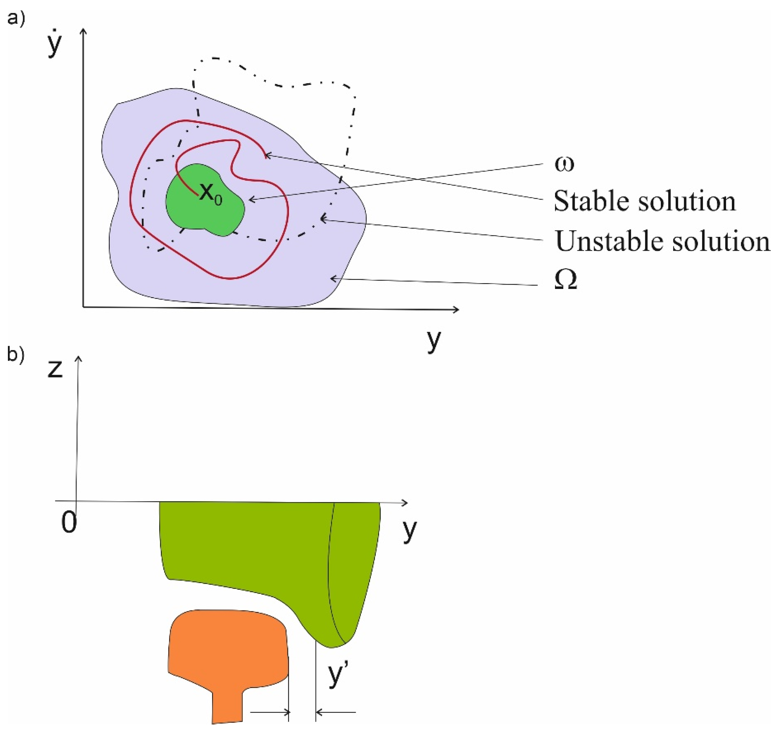
This paper presents the definition of the stochastic technical stability (STS) used to study a mathematical model of a passenger car moving at speeds higher than 160 km/h. The study of mathematical models of mechanical systems determined by Lagrange’s principle of the second kind or by d’Alambert’s principle or electrical systems determined by Maxwell’s principle is carried out in many directions. One of the elements of analytical research is stability in the sense of Lyapunov (such research concerns only mathematical models). Several definitions of stability in the Lyapunov sense are known, e.g., asymptotic, orbital, Lagrange, Poisson, technical and technical-stochastic (STS). In all cases (except STS), the study of stability of nonlinear systems is the determination of the Lyapunov function V (mostly guessed, since there is no method for determining this function). Moreover, in mathematical modeling there are perturbations which are assumed to be realizations of a stochastic process; this applies only to STS stability studies. In this paper, the definition of STS is taken from the work [35] and is presented in Section two of the paper. It has been proposed to use STS in stability studies in the sense of Lyapunov nonlinear mathematical models of a rail vehicle with perturbations (forcing) in the form of realization of a stochastic process. The definition of STS is illustrated on the phase plane and presented in Figure 1. The disturbances occurring in the track are presented in the form of realization of a stochastic process, illustrating the change of the track gauge. The presented method can be used to study both nonlinear models with random disturbances of mechanical and electrical systems.
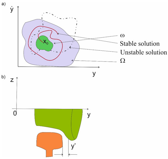
Figure 1.
Graphical interpretation of the stochastic technical stability in the wheel–rail system (a) STS phase plane, (b) the wheel–rail system.
In this paper, the STS study of a nonlinear mathematical model of a passenger car was carried out by perturbing the motion of the mathematical model with inequalities originating from the change of the track gauge and the motion of the wheel set in the direction transverse to the track axis. The area of stable motion in the Lyapunov sense was defined using the STS method. Simulations were performed to determine the trajectory of the wheelset transverse motion. Probabilities of finding oneself in the area of stable motion of the wheelset in relation to the rail were determined. In practice, it is a one-point contact of the wheel with the rail. Conclusions from the research are presented.
2. Materials and Methods
Notion of Stochastic Technical Stability (STS)
Let us consider the differential equation [35]:
where:
t—time, v—element of a set of elementary events; the vector stochastic process ξ represents the random track parameters b; yw, zw, ϕw—the parameters of inequality occurring at the turnout.
If we assume that the stochastic process f(0,t,) is absolutely integrable, i.e.,
where: P—probability, and that there exists a stochastic process absolutely integrable in the considered interval [0,T] such that the inequality
holds for (i.e., the Lipschitz condition is fulfilled with respect to x by the stochastic process , then it is possible to formulate the theorem that one solution of the Equation (1) exists and that this solution is an absolutely continuous stochastic process with a probability equal to one for t > t0.
Let us consider in turn two areas—ω and Ω—contained in the Euclidean space E, where ω is a limited, open and coherent set containing the origin of the system, while Ω is a limited and closed set and, moreover, . Let ε be the number fulfilling the inequality 0 < ε < 1. Then the definition of the stochastic technical stability (STS) is as follows: if every/each solution of e.g., (l) with initial conditions belonging to ω area belongs with a probability of 1 − ε to Ω area, then the system (in the Lyapunov sense) is stochastically technically stable in relation to ω, Ω areas and the process with a probability of 1 − ε, i.e.,
Graphic interpretation of the discussed problem is presented in Figure 1.
3. Mathematical Model of a Rail Vehicle
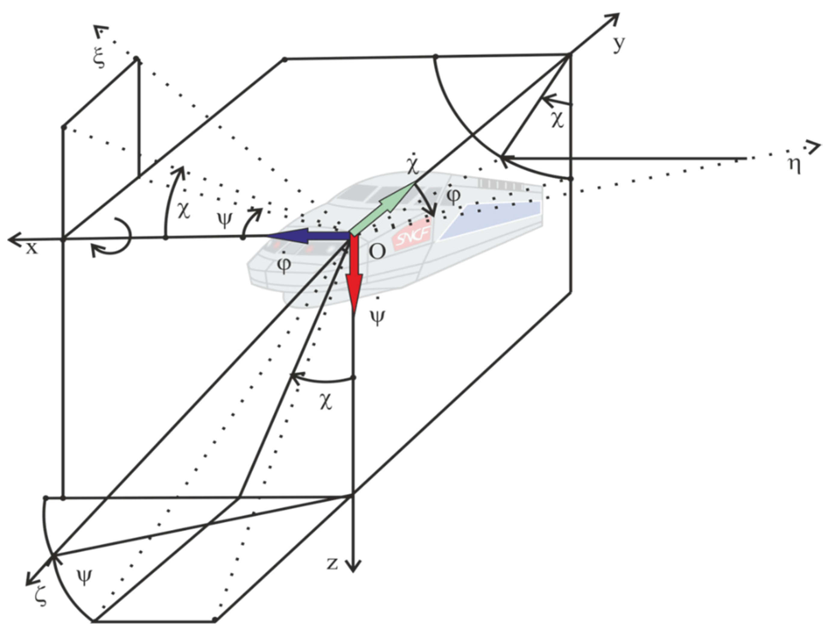
To model a mechanical rail vehicle track system, the right-handed, rectangular linear coordinate system and angular coordinates whose velocities (of corresponding angles) lie on the axes of the rectangular coordinate system were adopted. The arrangement is presented in Figure 2 (based on [37]).
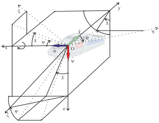
Figure 2.
Three independent rotation angles in relation to axes.
The coordinate system adopted in this way enables direct links between track irregularities, measured in accordance with the guidelines of prof. H. Bałuch [38], and appropriate coordinates. It was assumed that the transformation matrix was between inertial and non-inertial systems and had a zero-one value [39]. The adopted coordinate systems will apply to each solid in the nominal model of a rail vehicle (wheelset, bogie frame, body).
When building the mathematical model, the following assumptions were made:
- In a mathematical model of rail vehicle-track dynamics, contact occurrence, described in this article as Kalker’s linear theory, must be included. Contact occurrence is determined for two- and three-point contacts between the wheelset and the turnout.
- Normal force on a rail is a variable value and will be determined from a previous series of mathematical calculations completed for specific train parameters (wheelbase of wheelsets and bogies).
- The rail track was modelled as a Euler–Bernoulli beam on which a wheel rolls with v speed and contacts occur (an ellipse is formed of a and b parameters). The beam is supported by a track stiffness variable.
- In the dynamics of vehicle motion along the track, such phenomena as adhesion, microslips and material wear of wheels and rails have to be taken into account.
- A possibility of two contact ellipses occurring as a result of a wheel rolling on the rail and the blade was considered in the described model.
- Flexible elements between solids in the vehicle were assumed to be linear.
- Due to track stiffness, the railway vehicle-track system is nonlinear.
It was assumed that each vehicle would consist of the following elements: one body, two bogies, four wheelsets—as shown in Figure 3.

Figure 3.
Elements of a rail vehicle with coordinate systems.
Two types of constraints appear in the rail vehicle system: geometric and construction constraints.
Geometric constraints are shown below:
where
- 2b—the distance between contact points (wheel–rail) in the wheelset middle position,
- r—radius of a wheel being an element of the wheelset measured in the middle position,
- —coefficient that links the angular and transverse displacement of a wheelset.
Construction constraints are analyzed separately for each vehicle, e.g., the O1x coordinate will be the same for the bogie and the body.
In the description of the dynamics of a moving object, variables with a p index refer to the railroad car body, variables of the bogie are marked with w, while z denotes the wheelset variables.
The body and bogie each have five degrees of freedom (DOF); the displacement of body and bogie in the direction of y and z axes is marked as ; the rotations of the components listed around all three axes (x, y, z) are defined by , .
Each wheelset is described by three degrees of freedom uz,y, uz, and uz,z.
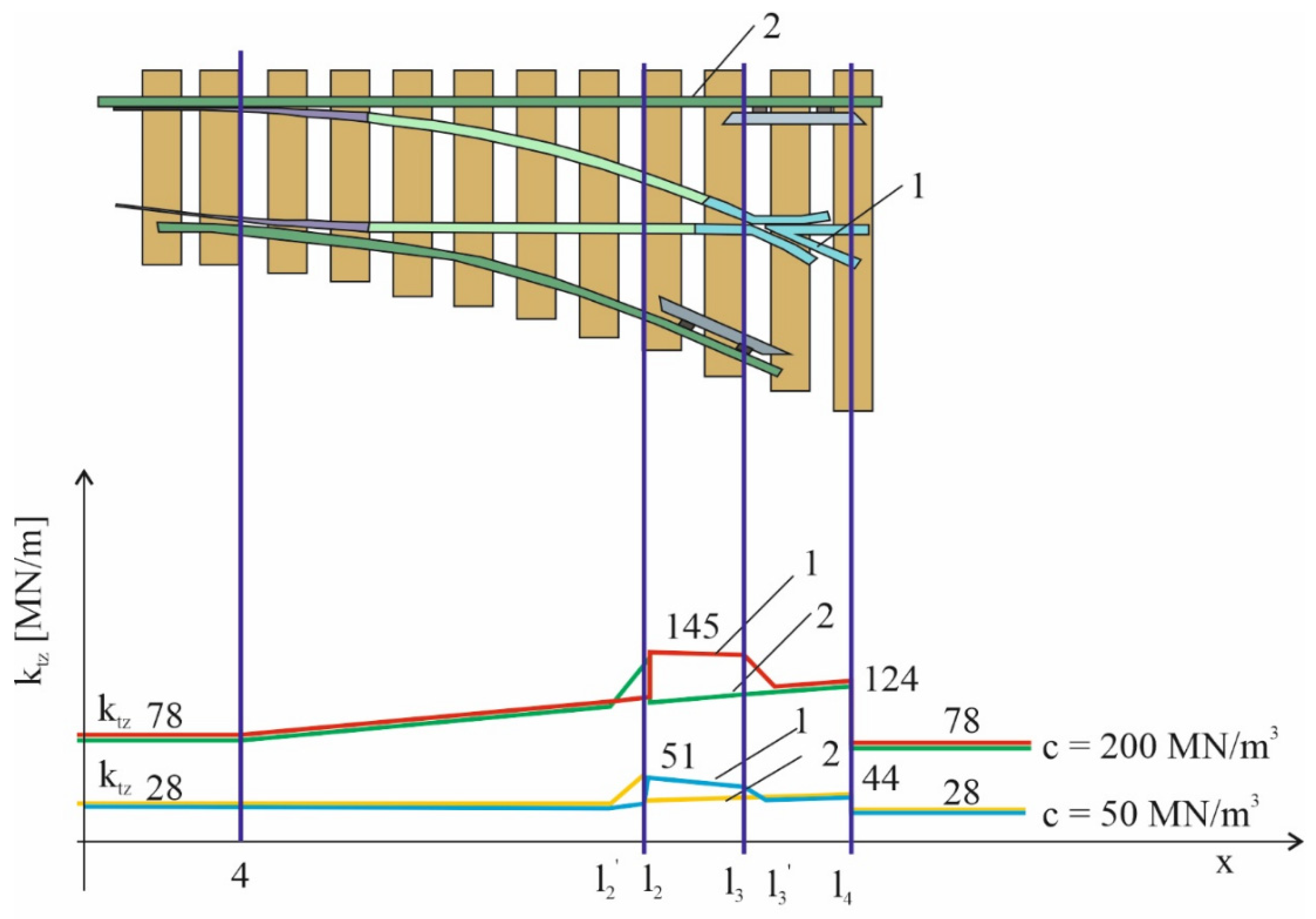
The disturbances from the irregular rail track (yw, and zw) and a change in track stiffness in the turnout area are based on [3] and are presented in Figure 4.
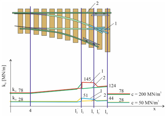
Figure 4.
The variability course of a vertical stiffness coefficient of two rail tracks at the turnout, with various values of a ballast coefficient: 1—internal track (with a frog), 2—external track.
Based on the train nominal model and defined equations of constraints, the equations of motion were derived by means of Lagrange equations of the second kind, in the following form:
Simulations were performed based on the equations above and with the parameters from Table 1 [55]. The parameters refer to a railway vehicle which can move with a speed of up to 350 km/h.

Table 1.
Parameters of the rail vehicle used in computer simulations.
4. Results
To perform a simulation, it is necessary to define the values of track irregularity in the turnout area. For modelling the dynamics of rail vehicles, the multi-body systems method is used more and more often due to the possibility of its easy application in automatic computer modelling of kinematics and dynamics of complex mechanical systems. Simulations carried out in Universal Mechanism using the multi-body method allow for rapid modelling and simulation of the design solution. The Universal Mechanism program enables such cooperation with the MATLAB/Simulink package, which allows for additional simulation of the control system. The data obtained during the simulation was processed and analyzed in MATLAB. A simulation model was created that reflects the real structure and the applicable laws of physics with acceptable accuracy. The main elements of the real structure, which have a direct influence on the dynamics of movement (wheelsets, bogie frame, body, elements of suspension) were taken into account in the model, but the elements of auxiliary equipment were omitted, taking into account the masses and moments of inertia, which the omitted elements introduce in reality. The calculations carried out concern a passenger car intended for high-speed traffic on a straight track. An analysis of the influence of the basic parameters of the vehicle suspension characteristics, mainly the lateral stiffness of the elastic elements, on the value of the critical speed has been carried out. In addition, a number of calculations were carried out to investigate the influence of the contact geometry parameter (equivalent conicity) on asymptotic stability in straight track traffic. This involved determining the value of the critical velocity as a function of the equivalent conicity parameter.
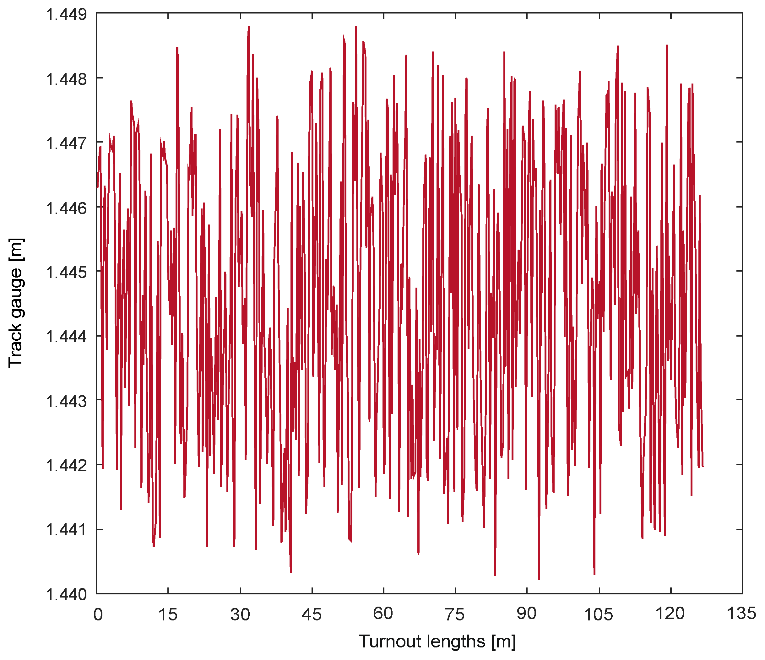
These were drawn from [36]. The parameter which affects the y’ parameter (Figure 1) is a track gauge. The track gauge is presented in Figure 5.
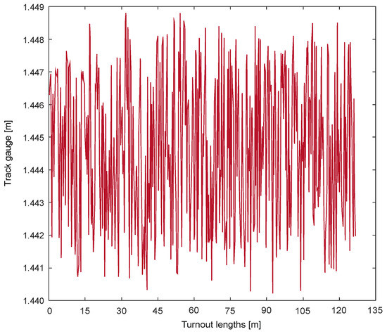
Figure 5.
Track gauge in the rail turnout.
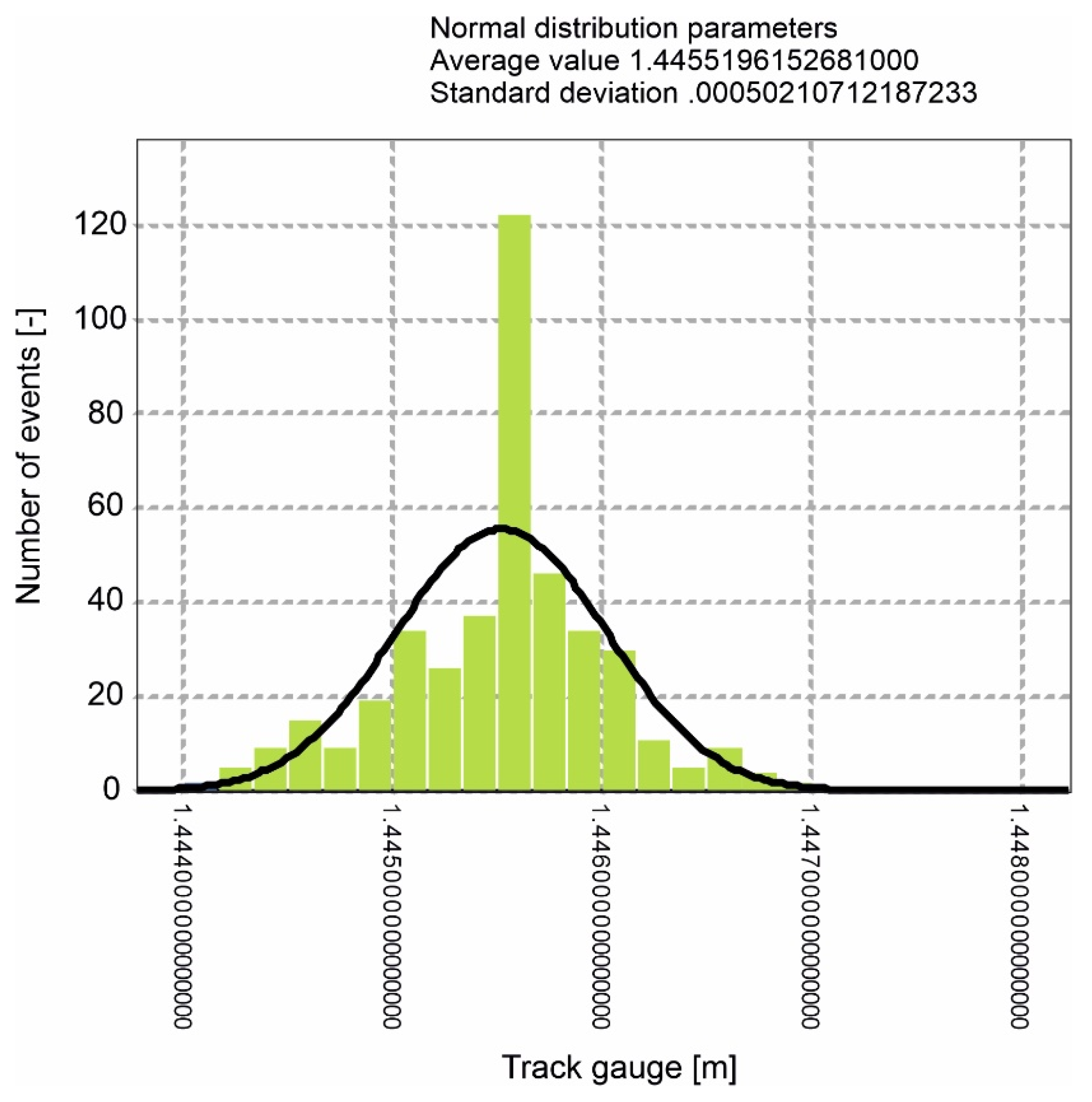
As seen in Figure 5, the track gauge varies from 1440.5 m to 1448.5 m. For this gauge, a histogram was made and normal distribution selected as shown in Figure 6.
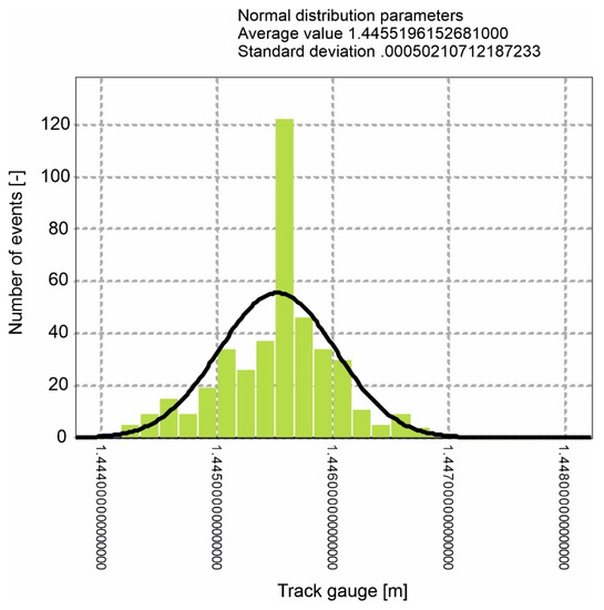
Figure 6.
Track gauge normal distribution in the rail turnout.
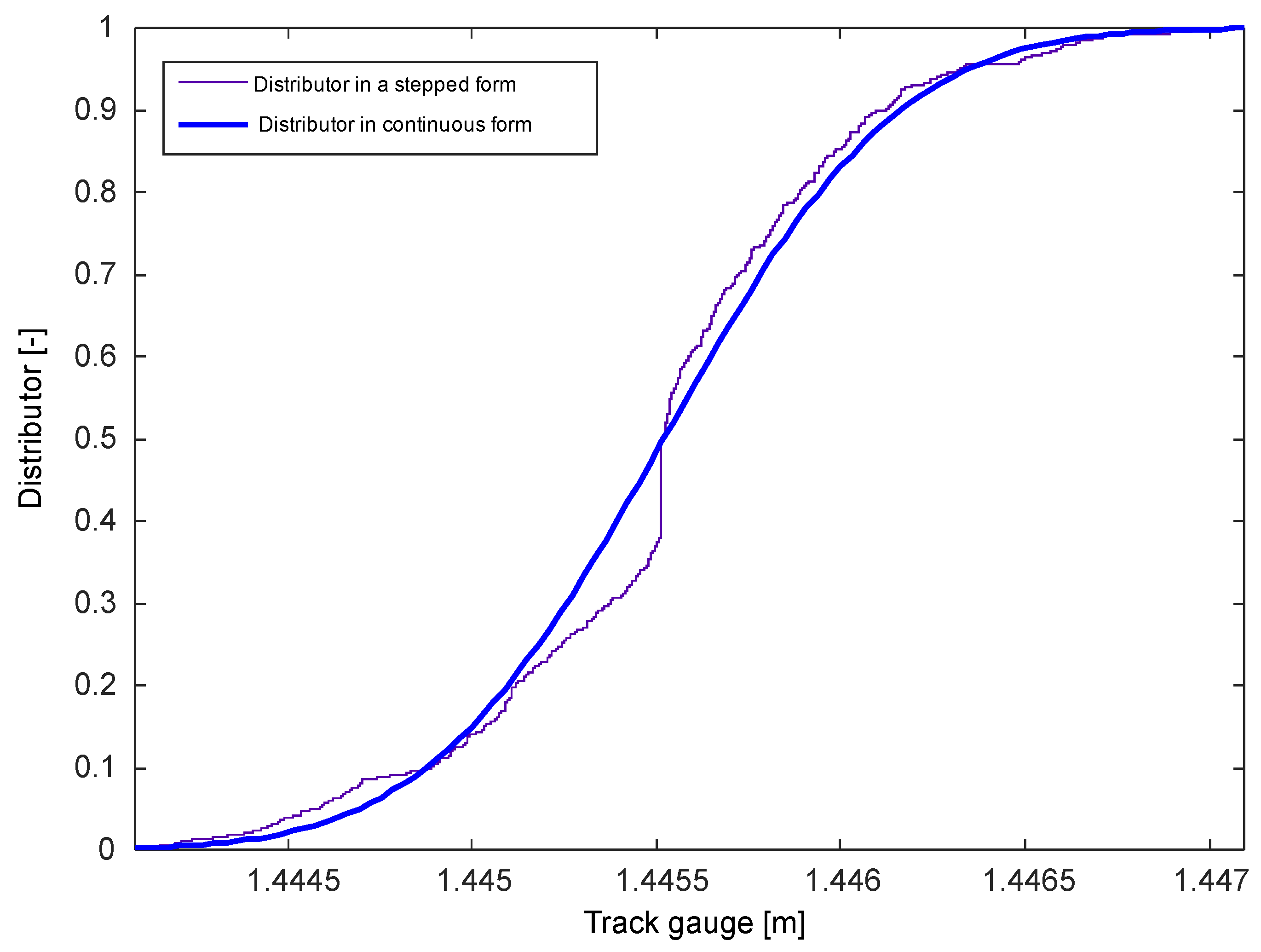
The step curve and distribution function were marked successively, as shown in Figure 7.
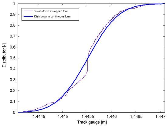
Figure 7.
Track gauge distribution function in a rail turnout.
In the simulation process these quantities will be the variables to describe the turnout for trains with selected speeds. According to Figure 1, the area is 5 mm. If the trajectory of y solutions or a wheelset in the transverse direction occurs in this area, we assume the mathematical model to possess stochastic technical stability (the definition in Section 2).
The varying track gauge results in an increase or decrease of the area.
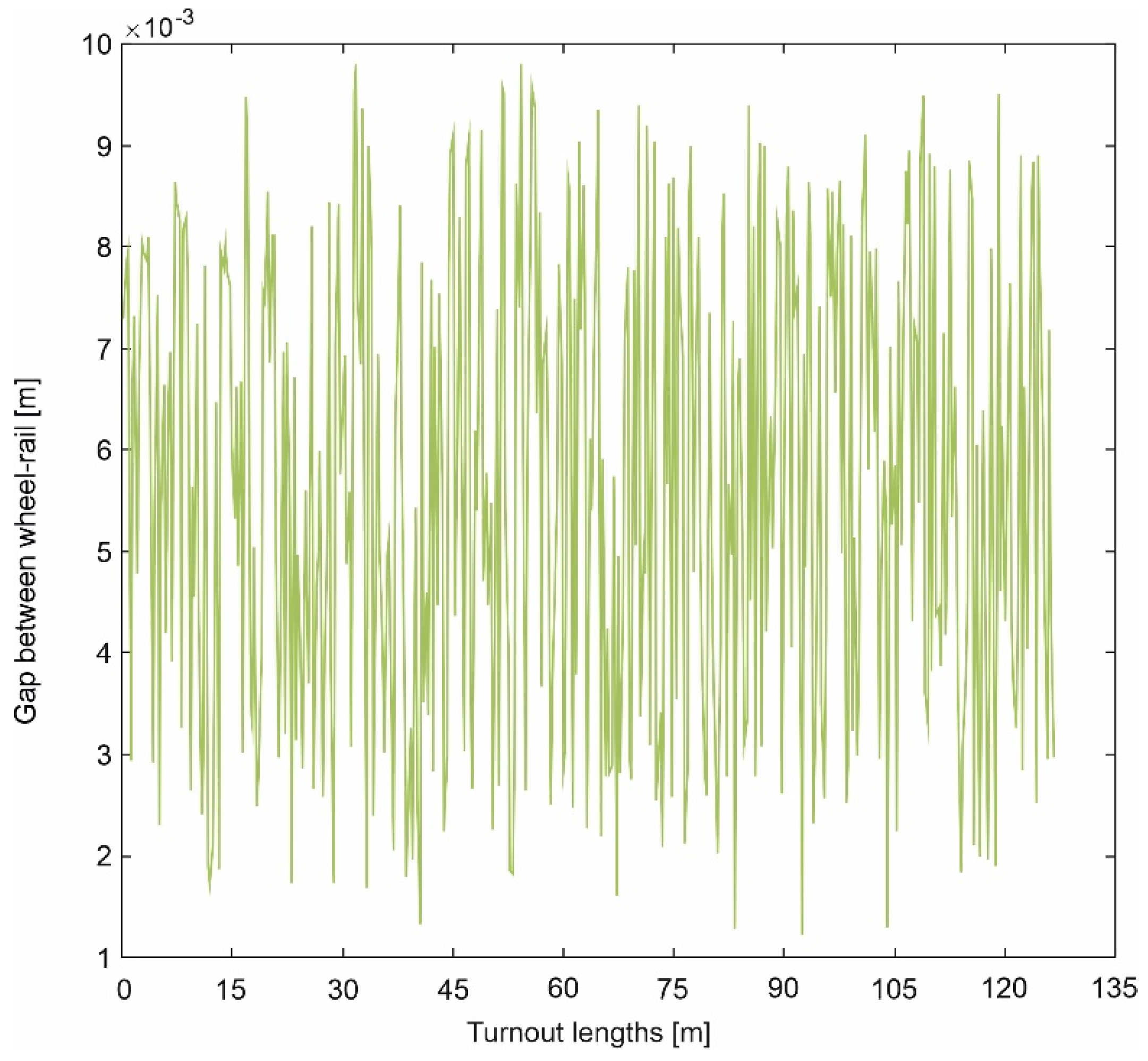
For each turnout point, the distance value between the rail head and the rim of the wheelset was determined ( area)—it was called a gap. This is a variable quantity in a turnout. The range of these changes in the gap are presented in Figure 8.
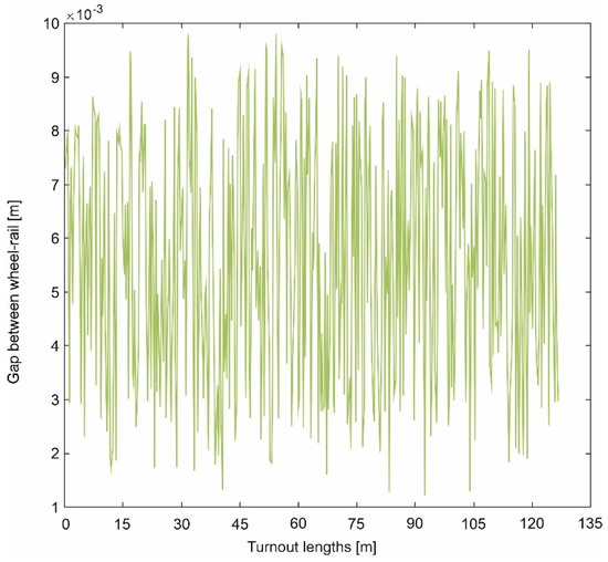
Figure 8.
The gap between a wheel -rail of the railway turnout.
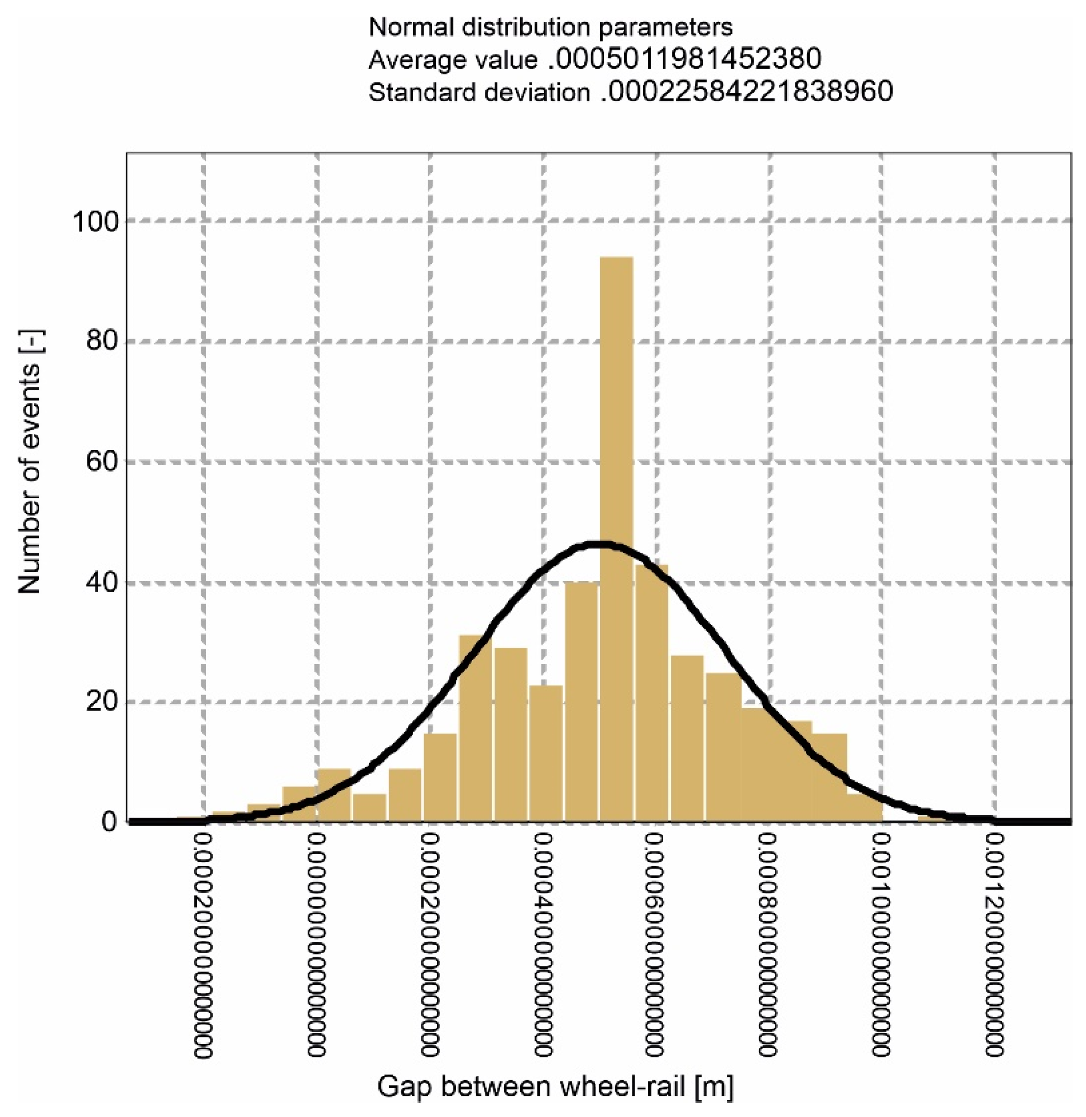
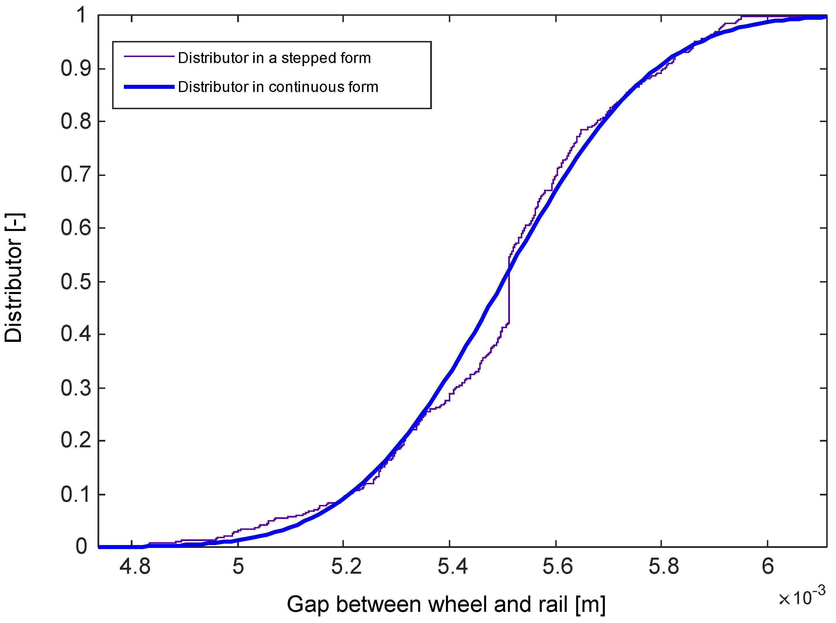
Then, the probability density function and distribution function were established. All selections for the probability density and distribution functions were determined with the Kolmogorov–Smirnov test at the significance level. This is presented in Figure 9 and Figure 10.
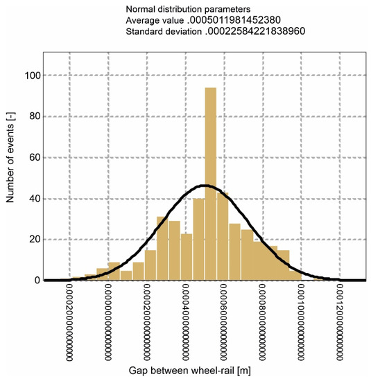
Figure 9.
Normal distribution for a wheel–rail gap in the rail turnout.
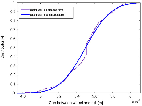
Figure 10.
Distribution function for a wheel–rail gap in the rail turnout.
The functions (Figure 5 and Figure 8) for a given turnout do not change despite their random nature.
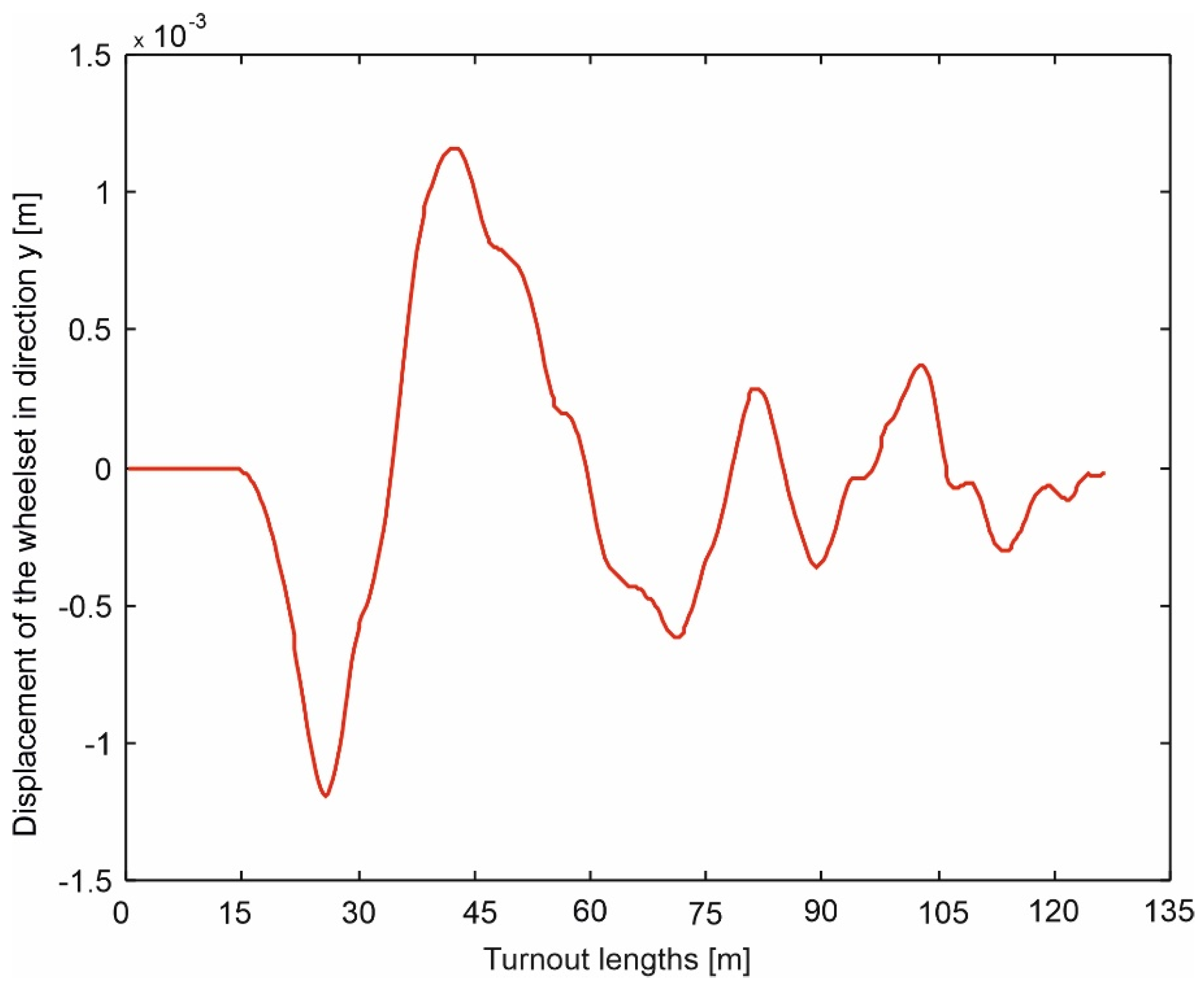
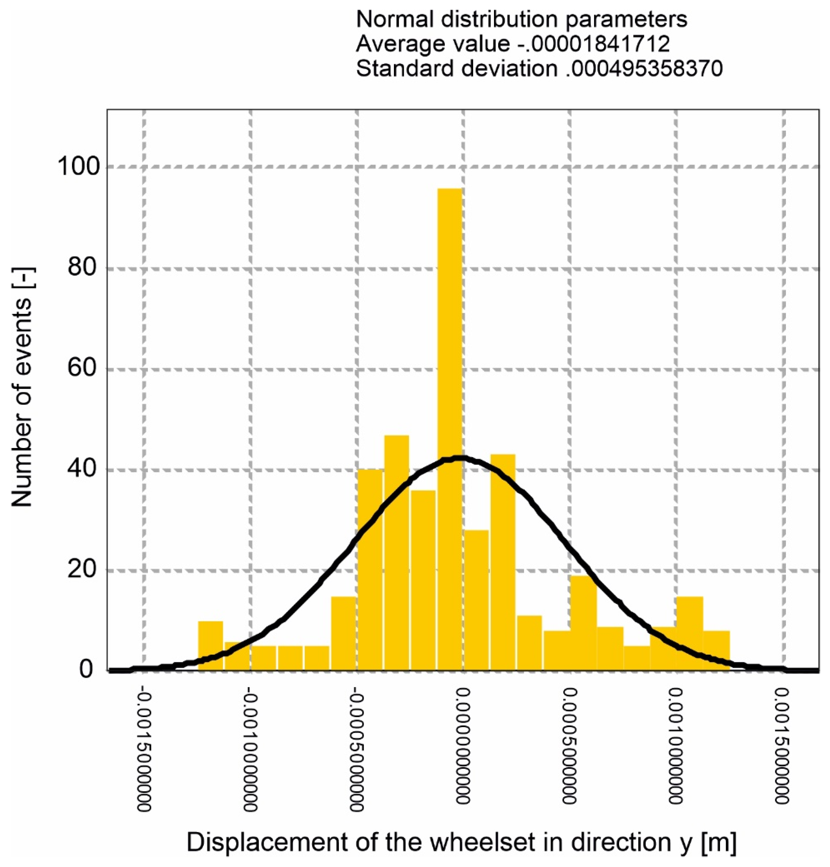
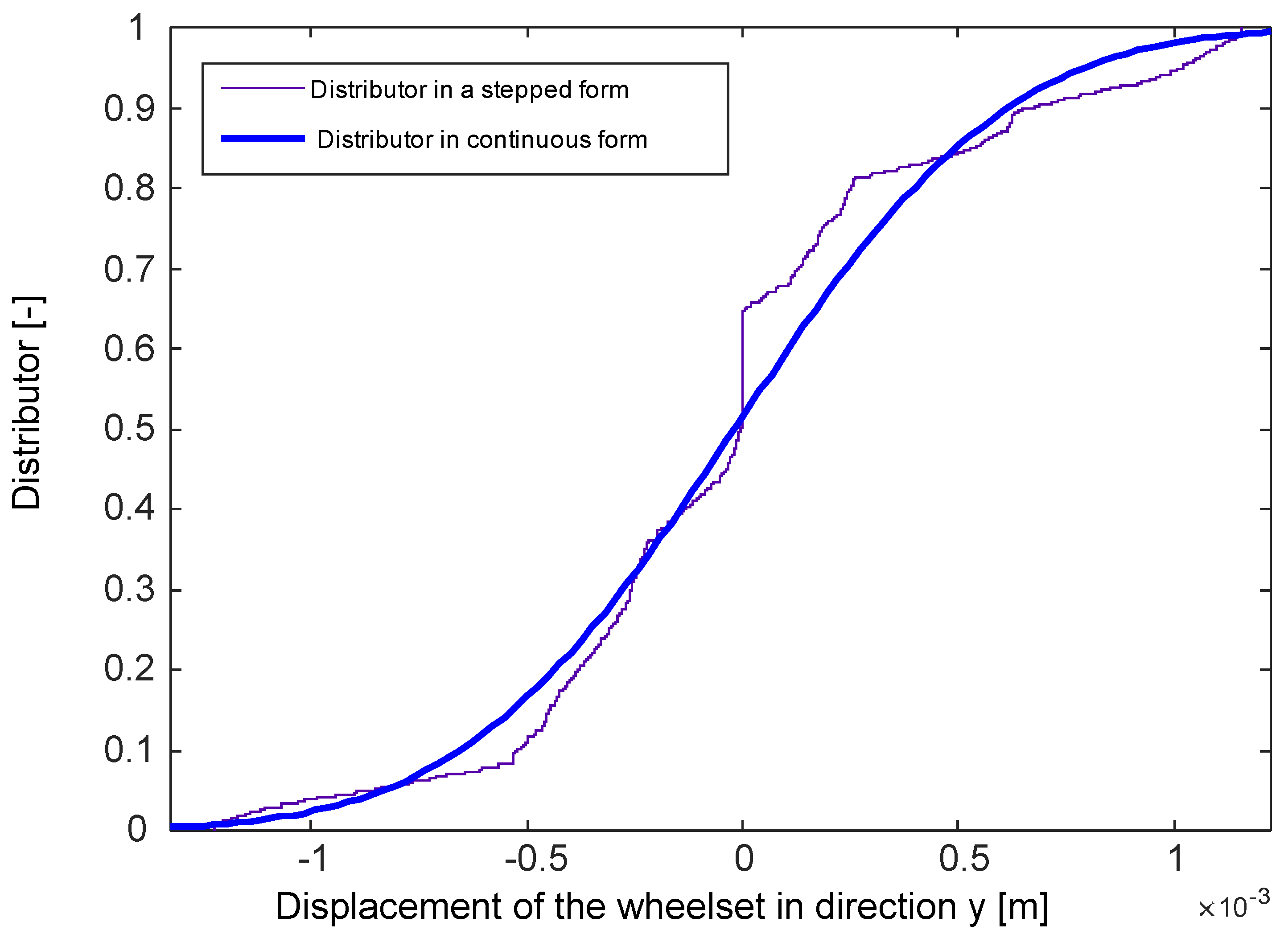
To mark the area for a given point of the turnout, it is necessary to perform a simulation of a train crossing the turnout. As a result, the y trajectory of the wheelset is obtained. This value is different at each point of the turnout. Subtracting this value from a gap at the given point, we receive the area and calculate its probability distribution and distribution function. Next, we indicate the probability of the trajectory being outside the area, which, according to the definition in Section 2, is the instability criterion of a railway vehicle mathematical model. Figure 11 presents the trajectory of a wheelset motion in y direction when crossing the turnout at a speed of 200 km/h. Figure 12 and Figure 13 show the probability and distribution function.
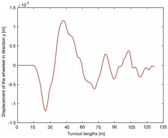
Figure 11.
Displacement of a wheelset in y direction determined for a train crossing the turnout on a straight track with a speed of v = 200 km/h.
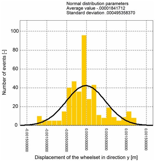
Figure 12.
Normal distribution for the displacement of the wheelset in y direction determined for a train crossing the turnout on a straight track with a speed of v = 200 km/h.
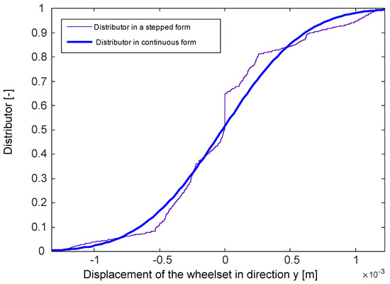
Figure 13.
Distribution function for the displacement of the wheelset in y direction indicated for a train crossing the turnout on a straight track with a speed of v = 200 km/h.
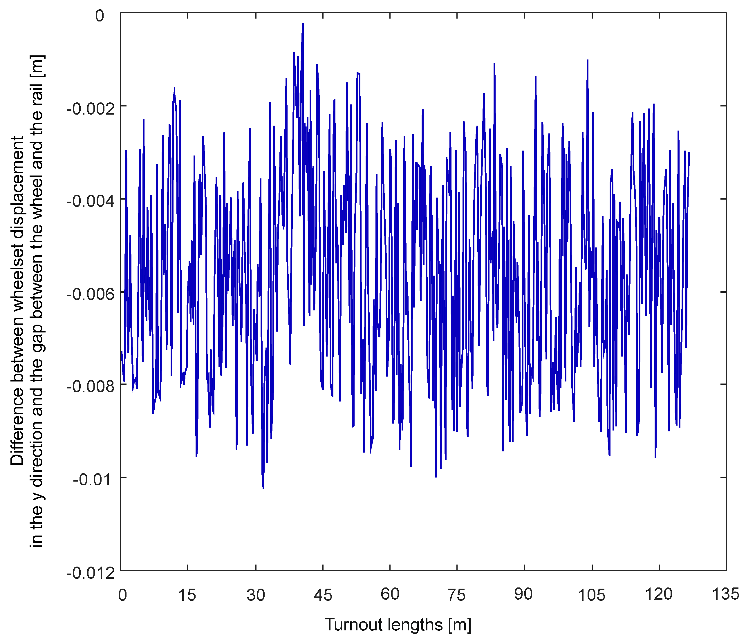
At each turnout point, the difference between the rail head and the wheelset rim was searched for, determining the difference between the current gap value and the displacement resulting from the trajectory of wheelset motions in the y direction. This brings about the determination of the area. The results for 200 km/h are presented in Figure 14.
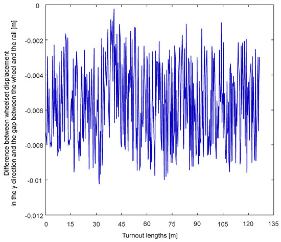
Figure 14.
The difference between displacement and a gap for a train crossing the turnout along a straight track with a speed of v = 200 km/h.
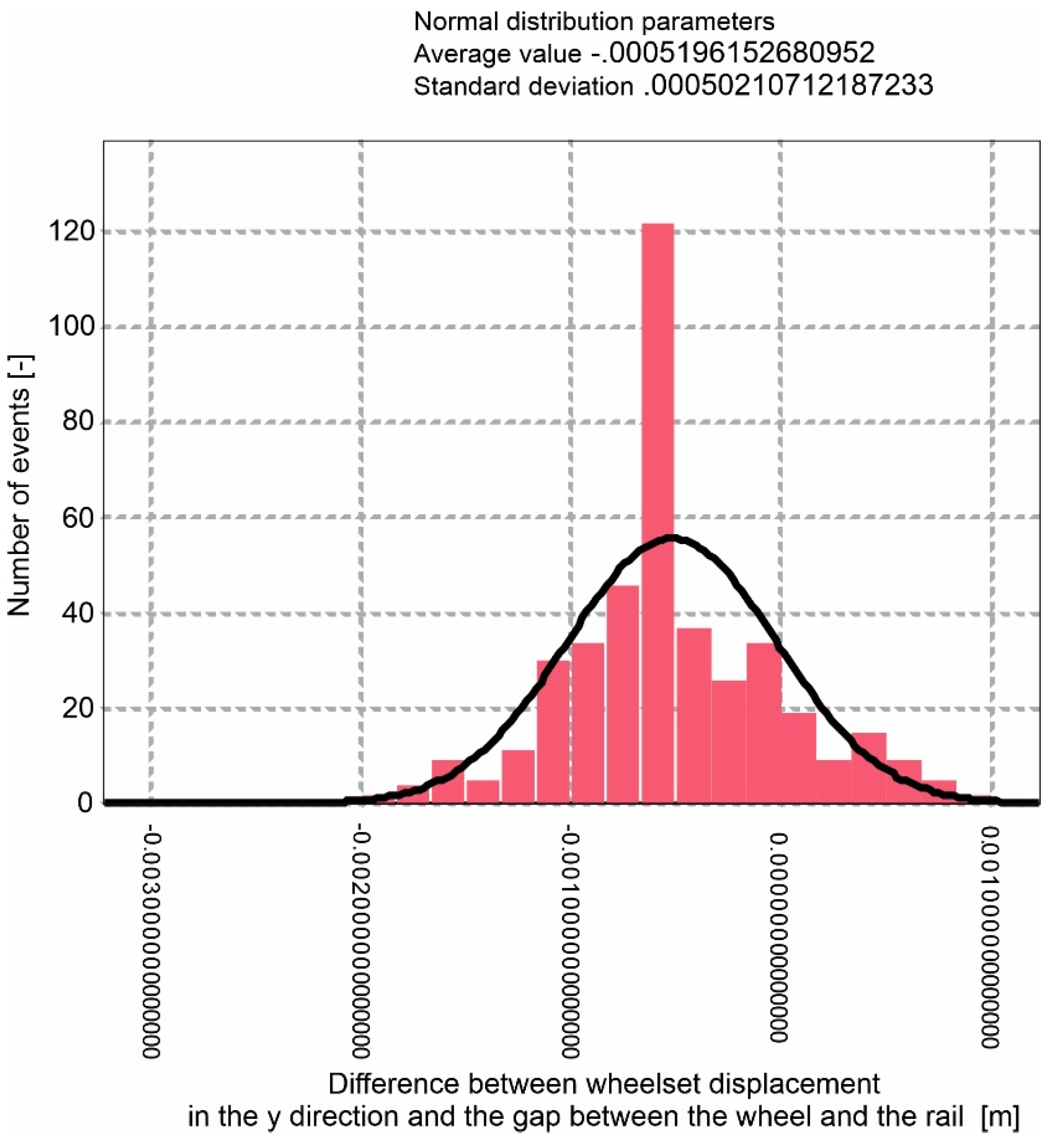
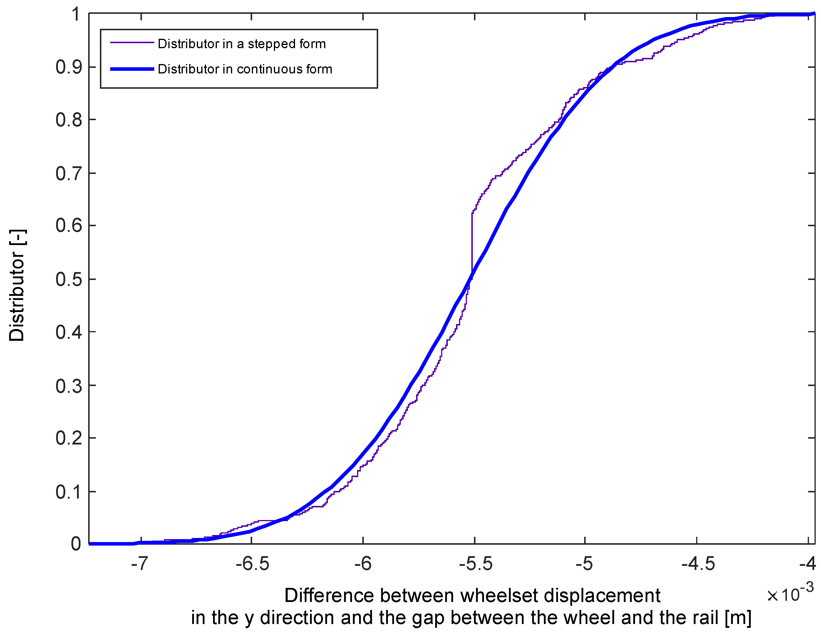
Subsequently, normal distribution and a distribution function were determined for that variable, which is shown in Figure 15 and Figure 16.
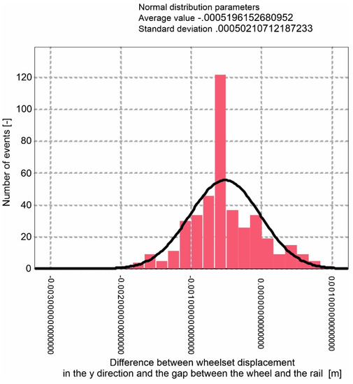
Figure 15.
Normal distribution for the difference between displacement and a gap for a train crossing the turnout along a straight track at a speed of v = 200 km/h.
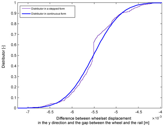
Figure 16.
Distribution function for the difference between displacement and a gap for a train crossing the turnout along a straight track with a speed of v = 200 km/h.
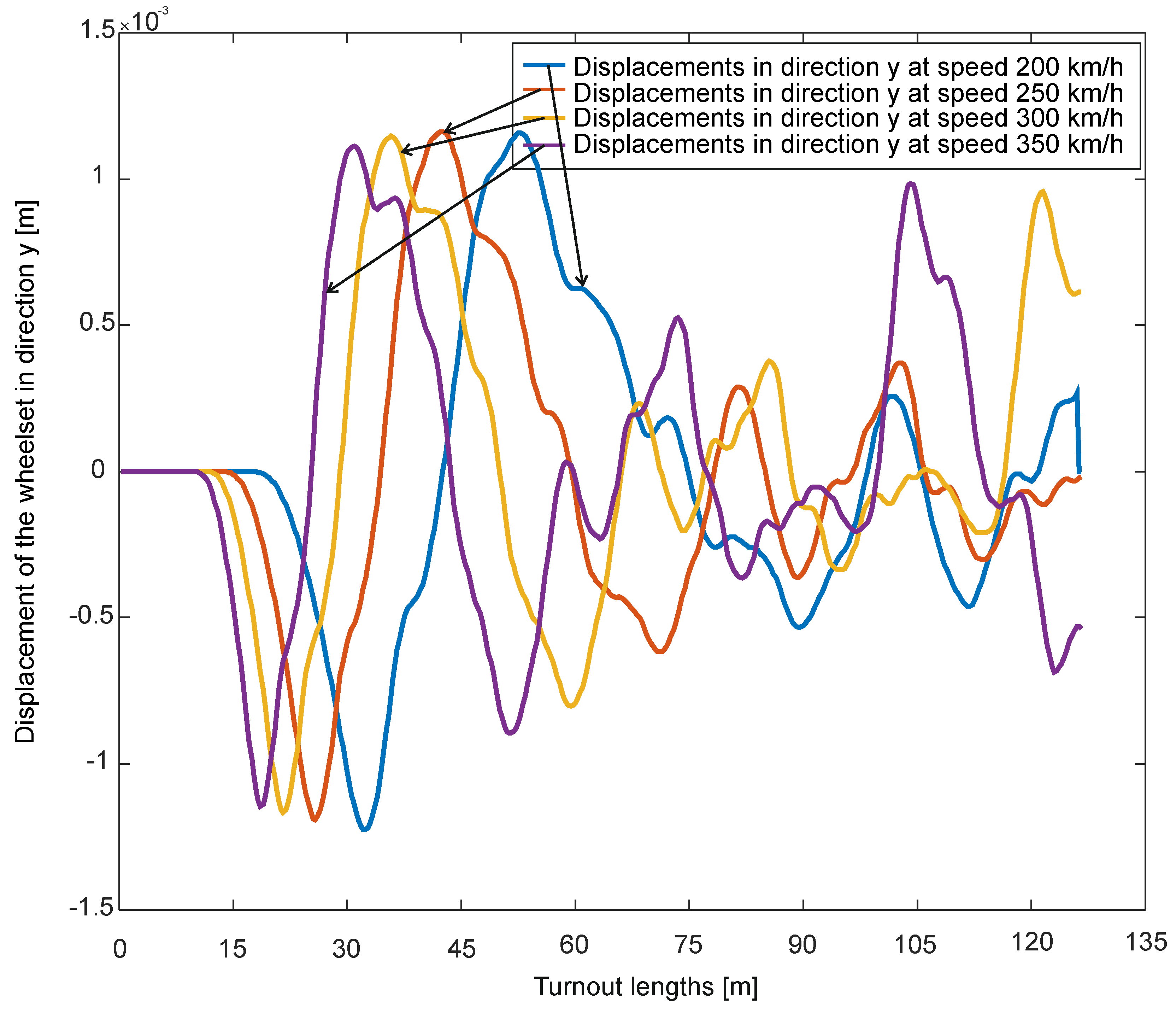
Identical simulations were performed for the speeds of 250 km/h, 300 km/h and 350 km/h.
The trajectory of a wheelset displacement for these speeds is presented in Figure 17.
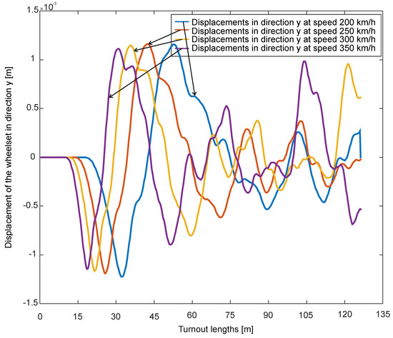
Figure 17.
Displacement of the wheelset in y direction at various speeds.
Next, the value of a gap for particular speeds was determined (the difference between the transverse displacement of the wheelset and a gap resulting from the track gauge). Probability distributions and distribution functions were marked. The parameters of the functions are as follows:
- -
- for 250 km/h: average value: −0.000513834692; standard deviation: 0.000485753384
- -
- for 300 km/h: average value: 0.00036598735; standard deviation: 0.000503405022
- -
- for 350 km/h: average value: −0.000385392073; standard deviation: 0.000570222943.
As a result of these simulations, the difference between the wheelset displacement and the gap was defined (the size of a gap at a given point of the turnout is the same for all simulations—the same turnout, the same irregularity).
For particular speeds, the probability of a 0-value gap between the wheelset and the head of the rail was drawn. According to the criterion presented in Section 2, the wheelset motion trajectory will be on the boundary of , which indicates that the system is technically stochastically stable. For the model of a rail vehicle crossing the turnout, the probability of motion trajectory hitting the boundary of the area was determined. Going beyond this area means that the motion is unstable in a technical stochastic sense. For the speed of 200 km/h or 250 km/h, the probability amounts to 0.85. For the speed of 300 km/h and 350 km/h, the probability of the wheelset motion trajectory to be found on the boundary of area is between 0.23 and 0.25.
This leads to the conclusion that the probabilities of finding a rail vehicle represented by the wheelset trajectory for the speeds of 200 km/h and 250 km/h, and for 300 km/h and 350 km/h are essentially different. The probability of unstable motion at 200 km/h or 250 km/h is 0.15, while at the speed of 300 km/h and 350 km/h it is 0.77 and 0.75, respectively. These results allow the assessment of technical stochastic stability of a rail vehicle (given parameters of a rail vehicle and given parameters of a turnout).
5. Conclusions
The test results presented make it possible to carry out tests for any rail vehicle and any turnout, indicating their dynamic features which affect the defined technical stochastic stability. According to publication [4], this stability corresponds to Lyapunov stability criterion.
The probability of unstable motion for speeds of 300 km/h and 350 km/h is due to the increase in vertical force, which also causes an increase in force in the transverse direction. Such force magnitudes will cause the trajectory of the wheelset motion in the transverse direction to have larger values. The values of the vertical and transverse forces for the motion through the turnout are taken from the work. Studying this type of stability is a very convenient tool for verifying the stability of real objects with disturbances.
Such tests are also suitable for establishing the conditions of single- and two-point wheel–rail contact. The tests may be carried out for other coordinates describing the wheelset motion.
Author Contributions
Conceptualization, J.K. and E.K.-A.; methodology, J.K.; software, J.K.; validation, J.K., E.K.-A.; formal analysis, J.K.; investigation, J.K.; resources, J.K.; data curation, J.K.; writing—original draft preparation, J.K.; writing—review and editing, J.K.; visualization, J.K.; supervision, J.K.; project administration, J.K.; funding acquisition, E.K.-A. All authors have read and agreed to the published version of the manuscript.
Funding
This research received no external funding.
Institutional Review Board Statement
Not applicable.
Data Availability Statement
Not applicable.
Conflicts of Interest
The authors declare no conflict of interest.
References
- Wickens, A.H. Steering and Dynamic Stability of Railway Vehicles. Veh. Syst. Dyn. 1976, 5, 15–46. [Google Scholar] [CrossRef]
- Wickens, A.H. Fundamentals of Rail Vehicle Dynamics, Guidance and Stability; Swets&Zeitlinger, B.V.: Lisse, The Netherlands, 2003. [Google Scholar]
- Wickens, A. The dynamic stability of railway vehicle wheelsets and bogies having profiled wheels. Int. J. Solids Struct. 1965, 1, 319–341. [Google Scholar] [CrossRef]
- Knothe, K.; Stichler, S. Rail Vehicle Dynamics; Springer: Berlin/Heidelberg, Germany, 2003. [Google Scholar]
- Popp, K.; Schiehlen, W. System dynamics and Long-Term Behaviour of Railway Vehicles, Track and Subgrade; Springer: Berlin/Heidelberg, Germany, 2003. [Google Scholar]
- Dukkipati, R.V.; Amyot, J.R. Simulation in Railway Dynamics Hardcover; North Oxford Academic: Banbury, UK, 1986. [Google Scholar]
- Dukkipati, R.V.; Garg, V.K. Dynamics of Railway Vehicle Systems; Academic Press: Cambridge, MA, USA, 1984. [Google Scholar]
- Dukkipati, R.V.; Dong, R. Impact loads due to wheel flats and shells. Veh. Syst. Dyn. 1992, 31, 1–22. [Google Scholar] [CrossRef]
- Dukkipati, R.V.; Garg, V.K. Lateral Stability of Railway Vehicles on Tangent Track. Veh. Syst. Dyn. 1984, 225–262. [Google Scholar]
- Dukkipati, R.V.; Dong, R.G.; Sankar, S. A finite element model of railway track and its application to the wheel flat problem. Proc. Inst. Mech. Engrs. Part F J. Rail Rapid Transit 1994, 208, 61–72. [Google Scholar] [CrossRef]
- de Pater, A.D. Die untersuchung der stabilitat der bewegung eines eisenbahnfahrzeuges mit hilfe der neumarkschen methode. Ing. Arch. 1980, 49, 195–200. [Google Scholar] [CrossRef]
- Elkins, J.; Carter, A. Testing and Analysis Techniques for Safety Assessment of Rail Vehicles: The State-of-the-Art. Veh. Syst. Dyn. 1993, 22, 185–208. [Google Scholar] [CrossRef]
- Andersson, C.; Dahlberg, T. Wheel/rail impacts at a railway turnout crossing. Proc. Inst. Mech. Eng. Part F J. Rail Rapid Transit 1998, 212, 123–134. [Google Scholar] [CrossRef]
- Yang, Y.-B.; Lin, B.-H. Vehicle-Bridge Interaction Analysis by Dynamic Condensation Method. J. Struct. Eng. 1995, 121, 1636–1643. [Google Scholar] [CrossRef]
- Dukkipati, R.V. Vehicle Dynamics; Narosa Publishing House: New Delhi, India, 2000. [Google Scholar]
- Hague, I.; Lieh, J. A study of parametric stability of railway vehicles. Int. J. Veh. Des. 1993, 14, 246–260. [Google Scholar] [CrossRef]
- Goldhirsch, I.; Sulem, P.; Orszag, S.A. Stability and Lyapunov stability of dynamical systems: A differential approach and a numerical method. Phys. D 1987, 27, 311–337. [Google Scholar] [CrossRef]
- Goverde, R.M. Railway timetable stability analysis using max-plus system theory. Transp. Res. Part B 2006, 41, 179–201. [Google Scholar] [CrossRef]
- Hannebrink, D.N.; Lee, H.S.H.; Weinstock, H.; Hedrick, J.K. Closure to “Discussion of ‘Influence of Axial Load, Track Gage, and Wheel Profile on Rail Vehicle Hunting’”. J. Eng. Ind. 1977, 99, 926–927. [Google Scholar]
- Newton, S.G.; Clark, R.A. An Investigation into the Dynamic Effects on the Track of Wheelflats on Railway Vehicles. J. Mech. Eng. Sci. 1979, 21, 287–297. [Google Scholar] [CrossRef]
- Polach, O. Application of nonlinear stability analysis in railway vehicle industry. In Non-Smooth Problems in Vehicle Systems Dynamics; Springer: Berlin/Heidelberg, Germany, 2009; pp. 15–27. [Google Scholar]
- True, H. Dynamics of a Rolling Wheelset. Appl. Mech. Rev. 1993, 46, 438–444. [Google Scholar] [CrossRef]
- Kisilowski, J.; Kardas-Cinal, E. On a Certain Method of Examining Stability of Mathematical Models of Railway Vehicles with Disturbances Occurring in Real Objects. Veh. Syst. Dyn. 1994, 23, 262–273. [Google Scholar] [CrossRef]
- Kardas-Cinal, E. Study of the Technical Stability of the Stochastic Mathematical Model of a Rail Vehicle. Ph.D. Thesis, Warsaw University of Technology, Warsaw, Poland, 1994. [Google Scholar]
- Fermer, M.; Niesen, J.C.O. Vertical interaction between train and track with soft and stiff railpads–full-scale experiments and theory’. Proc. Inst. Mech. Engrs. Part F J. Rail Rapid Transit 1995, 209, 39–47. [Google Scholar] [CrossRef]
- He, Y.; McPhee, J. Optimization of the Lateral Stability of Rail Vehicles. Veh. Syst. Dyn. 2002, 38, 361–390. [Google Scholar] [CrossRef]
- Horak, D.; Wormley, D.N. Nonlinear Stability and Tracking of Rail Passenger Trucks. J. Dyn. Syst. Meas. Control. 1982, 104, 256–263. [Google Scholar] [CrossRef]
- Ingwerson, D.R. A Modified Lyapunov Method for Nonlinear Stability Problems. IRE Trans. Autom. Control 1961, 6, 199–210. [Google Scholar] [CrossRef]
- Law, E.H.; Karogal, I.; Ayalew, B. An Iterative Approach for Steady State Handling Analysis of Vehicles. In Proceedings of the n International Design Engineering Technical Conferences and Computers and Information in Engineering Conference, Brooklyn, NY, USA, 3–6 August 2008; IDETC-CIE2008. pp. 641–649. [Google Scholar] [CrossRef]
- Law, E.H.; Cooperrider, N.K. A Survey of Railway Vehicle Dynamics Research. J. Dyn. Syst. Meas. Control 1974, 96, 132–146. [Google Scholar] [CrossRef]
- Wu, H.; Zeng, X.-H.; Lai, J.; Yu, Y. Nonlinear hunting stability of high-speed railway vehicle on a curved track under steady aerodynamic load. Veh. Syst. Dyn. 2019, 58, 175–197. [Google Scholar] [CrossRef]
- Olusola, O.B.; Likins, P.W. Stability analysis of constant speed transit vehicles. Veh. Syst. Dyn. 1975, 4, 223–248. [Google Scholar] [CrossRef]
- Richard, J.A. Stability of railway-car running at high speed. Veh. Syst. Dyn. 1987, 16, 37–49. [Google Scholar] [CrossRef]
- Walker, J.A. On the Stability of Linear Discrete Dynamic Systems. J. Appl. Mech. 1970, 37, 271–275. [Google Scholar] [CrossRef]
- Bogusz, W. Stateczność Techniczna; IPPT PAN: Warsaw, Poland, 1972; p. 132. [Google Scholar]
- Kisilowski, J.; Skopińska, H. Dynamika Krzyżownicy Rozjazdu Zwyczajnego, Archiwum Inżynierii Lądowej–Tom XXIX 4/83; Warszawa, Poland, 1983. [Google Scholar]
- Kisilowski, J. Dynamika Układu tor- Pojazd, Prace ITPW, Zeszyt 15; Warsaw, Poland, 1978. [Google Scholar]
- Bałuch, H. Optymalizacja Układów Geometrycznych Toru; WKiŁ: Warsaw, Poland, 1983. [Google Scholar]
- Kisilowski, J. Dynamika Układu Mechanicznego Pojazd Szynowy-Tor; PWN: Warsaw, Poland, 1991. [Google Scholar]
- Bell, C.E.; Horak, D.; Hedrick, J.K. Stability and Curving Mechanics of Rail Vehicles. J. Dyn. Syst. Meas. Control 1981, 103, 181–190. [Google Scholar] [CrossRef]
- Bracciali, A.; Cascini, G.; Ciuffi, R. Time Domain Model of the Vertical Dynamics of a Railway Track up to 5 kHz. Veh. Syst. Dyn. 1998, 30, 1–15. [Google Scholar] [CrossRef]
- Chung, W.-J.; Shim, J.-K. Influence Factors on Critical Speed Hysteresis in Railway Vehicles. JSME Int. J. Ser. C 2003, 46, 278–288. [Google Scholar] [CrossRef][Green Version]
- Cox, E.H.; Garg, V.K.; Goodspeed, C.H.; Singh, S.P. Comparative Study of the Linear and Non-Linear Locomotive Response. J. Dyn. Syst. Meas. Control 1979, 101, 263–271. [Google Scholar] [CrossRef]
- Cox, J.J.; Hedrick, J.K.; Cooperrider, N.K. Optimization of Rail Vehicle Operating Speed with Practical Constraints. J. Dyn. Syst. Meas. Control 1978, 100, 260–269. [Google Scholar] [CrossRef]
- Dym, C.L. Stability Theory and Its Applications to Structural Mechanics; Noordhoff International Publishing Co.: Leyden, The Netherlands, 1974. [Google Scholar]
- Goverde, R.M. Punctuality of Railway Operations and Timetable Stability Analysis. Ph.D. Thesis, Delft University of Technology, TRAIL Research School, Delft, The Netherlands, 2005. [Google Scholar]
- Guckenheimer, J.; Holmes, P. Nonlinear oscillations, dynamical systems, and bifurcations of vector fields. Appl. Math. Sci. 1983, 42, 462. [Google Scholar]
- Inozemtsev, V.; Tibilov, T. Lyapunov–Bautin bifurcation and the hunting of a railway wheelset. In Proceedings of the 2nd International Conference Control of Oscillations and Chaos, Scientific Counsil on Transoptation Problems of RAS, Moscow, St. Petersburg, Russia, 5–7 July 2000. [Google Scholar]
- Law, E.H.; Brand, R.S. Analysis of the Nonlinear Dynamics of a Railway Vehicle Wheelset. J. Dyn. Syst. Meas. Control 1973, 95, 28–35. [Google Scholar] [CrossRef]
- Lee, S.-Y.; Cheng, Y.-C. Nonlinear Analysis on Hunting Stability for High-Speed Railway Vehicle Trucks on Curved Tracks. J. Vib. Acoust. 2004, 127, 324–332. [Google Scholar] [CrossRef]
- Lei, X.; Nodab, N.A. Analyses of dynamic response of vehicle and track coupling system with random irregularity of track vertical profile. J. Sound Vib. 2002, 258, 147–165. [Google Scholar] [CrossRef]
- Nath, Y.; Jayadev, K. Influence of yaw stiffness on the nonlinear dynamics of railway wheelset. Commun. Nonlinear Sci. Numer. Simul. 2005, 10, 179–190. [Google Scholar] [CrossRef]
- Suda, Y. High Speed Stability and Curving Performance of Longitudinally Unsymmetric Trucks with Semi-active Control. Veh. Syst. Dyn. 1994, 23, 29–52. [Google Scholar] [CrossRef]
- Xu, G.; Troger, H.; Steindl, A. Global analysis of the loss of stability of a special railway bogy. In Nonlinear Dynamics in Engineering Systems; Springer: Berlin/Heidelberg, Germany, 1990; pp. 345–353. [Google Scholar]
- Yang, Y.-R. Limit Cycle Hunting of a Bogie with Flanged Wheels. Veh. Syst. Dyn. 1995, 24, 185–196. [Google Scholar] [CrossRef]
- Young, J.A.; Apparao, T.A.P.S. Lateral Dynamics of a Rail Transit Vehicle: A Comparison of Experimental and Theoretical Results. J. Dyn. Syst. Meas. Control 1981, 103, 39–48. [Google Scholar] [CrossRef]
- Kowalik, R. Wybrane Problemy Dynamiki Rozjazdu Kolejowego Przy Dużych Prędkościach Współczesnych Pociągów; Instytut Naukowo-Wydawniczy Spatium: Radom, Poland, 2020; e-ISBN: 978-83-66550-16-2. [Google Scholar]
- Gou, H.; Yang, L.; Mo, Z.; Guo, W.; Shi, X.; Bao, Y. Effect of Long-Term Bridge Deformations on Safe Operation of High-Speed Railway and Vibration of Vehicle–Bridge Coupled System. Int. J. Struct. Stab. Dyn. 2019, 19. [Google Scholar] [CrossRef]
- Zalewski, J. On a Certain Approach Towards the U-Turn of a Motor Vehicle Maneuver, Communications in Computer and Information Science; Springer: Cham, Switzerland, 2020; 1289 CCIS; pp. 354–367. [Google Scholar] [CrossRef]
- Uyulan, C.; Gokasan, M.; Bogosyan, S. Hunting stability and derailment analysis of the high-speed railway vehicle moving on curved tracks. Int. J. Heavy Veh. Syst. 2019, 26, 824. [Google Scholar] [CrossRef]
- Zalewski, J. Selected Problems of a Motor Vehicle Motion in a Turn after Steering Wheel Release, Communications in Computer and Information Science; Springer: Cham, Switzerland, 2019; Volume 1049, pp. 273–286. [Google Scholar] [CrossRef]
- Kim, H.-W.; Cha, H.-R. Sliding Mode-Based Slip Control of Compact Electric Vehicle Truck for Varying Load and Yaw Rate. Appl. Sci. 2021, 11, 6465. [Google Scholar] [CrossRef]
- Nguyen, A.-T.; Rath, J.; Lv, C.; Guerra, T.-M.; Lauber, J. Human-Machine Shared Driving Control for Semi-Autonomous Vehicles Using Level of Cooperativeness. Sensors 2021, 21, 4647. [Google Scholar] [CrossRef] [PubMed]
- Wilhelm, T.; Dorsch, V.; Gauterin, F. Mass Data Measurement, Approximation and Influence on Vehicle Stability for Ultra-Light Human-Powered Vehicles. Appl. Sci. 2021, 11, 5485. [Google Scholar] [CrossRef]
- Lei, T.; Wang, J.; Yao, Z. Modelling and Stability Analysis of Articulated Vehicles. Appl. Sci. 2021, 11, 3663. [Google Scholar] [CrossRef]
- Yang, K.; Dong, D.; Ma, C.; Tian, Z.; Chang, Y.; Wang, G. Stability Control for Electric Vehicles with Four In-Wheel-Motors Based on Sideslip Angle. World Electr. Veh. J. 2021, 12, 42. [Google Scholar] [CrossRef]
- Xue, X.; Cheng, K.; Chan, W.; Fong, Y.; Kan, K.; Fan, Y. Design, Analysis and Application of Single-Wheel Test Bench for All-Electric Antilock Braking System in Electric Vehicles. Energies 2021, 14, 1294. [Google Scholar] [CrossRef]
- Ni, T.; Li, W.; Zhao, D.; Kong, Z. Road Profile Estimation Using a 3D Sensor and Intelligent Vehicle. Sensors 2020, 20, 3676. [Google Scholar] [CrossRef]
- Che, F.; Niu, Y.; Li, J.; Wu, L. Cooperative Standoff Tracking of Moving Targets Using Modified Lyapunov Vector Field Guidance. Appl. Sci. 2020, 10, 3709. [Google Scholar] [CrossRef]
- Yim, S. Comparison among Active Front, Front Independent, 4-Wheel and 4-Wheel Independent Steering Systems for Vehicle Stability Control. Electronics 2020, 9, 798. [Google Scholar] [CrossRef]
- Gao, L.; Zhao, W.; Hou, B.; Zhong, Y. Analysis of Influencing Mechanism of Subgrade Frost Heave on Vehicle-Track Dynamic System. Appl. Sci. 2020, 10, 8097. [Google Scholar] [CrossRef]
- Zhang, X.; Wang, L.; Dunford, W.; Chen, J.; Liu, Z. Integrated Full-Frequency Impedance Modeling and Stability Analysis of the Train-Network Power Supply System for High-Speed Railways. Energies 2018, 11, 1714. [Google Scholar] [CrossRef]
Publisher’s Note: MDPI stays neutral with regard to jurisdictional claims in published maps and institutional affiliations. |
© 2021 by the authors. Licensee MDPI, Basel, Switzerland. This article is an open access article distributed under the terms and conditions of the Creative Commons Attribution (CC BY) license (https://creativecommons.org/licenses/by/4.0/).

