Article

A Novel Control Approach to Hybrid Multilevel Inverter for High-Power Applications

1
Department of Electrical Engineering, University of Engineering and Technology, Mardan 23200, Pakistan
2
Department of Electrical and Computer Engineering, COMSATS University Islamabad, Islamabad 44000, Pakistan
3
Center of Intelligent Systems and Networks Research, University of Engineering and Technology, Peshawar 25000, Pakistan
4
Department of Electrical Engineering, University of Engineering and Technology, Peshawar 25000, Pakistan
5
Department of Computer Software Engineering, University of Engineering and Technology, Mardan 23200, Pakistan
6
Faculty of Electrical Engineering, Ostfold University College, 1757 Halden, Norway
*
Authors to whom correspondence should be addressed.
Energies 2021, 14(15), 4563; https://doi.org/10.3390/en14154563
Submission received: 7 June 2021 / Revised: 15 July 2021 / Accepted: 21 July 2021 / Published: 28 July 2021
(This article belongs to the Special Issue Dynamic Modelling and Control in Multilevel Converters)

Abstract

:
This paper proposes a hybrid control scheme for a newly devised hybrid multilevel inverter (HMLI) topology. The circuit configuration of HMLI is comprised of a cascaded converter module (CCM), connected in series with an H-bridge converter. Initially, a finite set model predictive control (FS-MPC) is adopted as a control scheme, and theoretical analysis is carried out in MATLAB/Simulink. Later, in the real-time implementation of the HMLI topology, a hybrid control scheme which is a variant of the FS-MPC method has been proposed. The proposed control method is computationally efficient and therefore has been employed to the HMLI topology to mitigate the high-frequency switching limitation of the conventional MPC. Moreover, a comparative analysis is carried to illustrate the advantages of the proposed work that includes low switching losses, higher efficiency, and improved total harmonic distortion (THD) in output current. The inverter topology and stability of the proposed control method have been validated through simulation results in MATLAB/Simulink environment. Experimental results via low-voltage laboratory prototype have been added and compared to realize the study in practice.

1. Introduction

Over recent decades, multilevel converters (MLCs) have found popular in high-power applications. The reasons for their widespread acceptance are the capability to share the high-voltage stresses among the devices, low conduction and switching losses, and improved power quality with minimum harmonic distortion [1,2]. An attempt to enhance the power quality to IEEE standards, i.e., 5% current total harmonic distortion (THD), necessitates the generation of higher output voltage levels of the converter. However, the increase in output voltage level requires more components and floating capacitors, which results in increased cost and size of the converter system. Hybrid converter topologies as a combination of the conventional converters have achieved great attention from researchers [3,4,5] due to their minimum requirement of components count. The hybrid converter is the cascade arrangement of dissimilar converters, which reduces the necessity of component requirements for the same output voltage levels.
Maintaining the power quality of the hybrid multilevel inverters (HMLIs) at acceptable standards (IEEE-519) is a challenge. Many advanced control methods have been developed in recent decades. The selective harmonic elimination pulse width modulation (SHE-PWM) [6] is a common control method used in the HMLIs. The SHE-PWM offers good switching losses control, but its modulation raises the angle calculation complexity. More advanced control techniques are applied to hybrid converters, namely the sinusoidal PWM (SPWM) [7,8] and the model predictive control (MPC) [9]. The MPC has been a promising control method for nearly three decades in industry and academia due to its numerous advantages for MLCs [10]. This control technique is easily realized with less tuning complexity and can also include nonlinear systems and constraints easily. Moreover, the MPC directly achieves its objectives without angular calculation and reference voltage approximation methods, which reduces its implementation complexity in power electronic systems [11]. Finite set model predictive control (FS-MPC) has been achieved popularity in power electronic systems due to its simple and flexible implementation [9]. The discrete nature of FS-MPC allows its direct implementation and eliminates the PWM need. The FS-MPC is discussed widely in the literature for controlling DC-DC and AC-DC converters [12,13,14,15], multilevel converters such as packed U-cell (PUC) [9], and flying capacitor-based ANPC hybrid converters in [16]. The FS-MPC comprises finite control actions, among which the optimal control action is attained by solving optimization problem [11]. Moreover, nonlinear control schemes, such as sliding mode control (SML) is used to control the switches of the multilevel converter and reduce the THD levels [17,18,19,20]. It is a robust and dynamic scheme that offers better performance, but much more complex and harder to designed and built.
In this paper, a circuit configuration of the proposed hybrid multilevel inverter (HMLI) based on the series arrangement of a cascaded converter module in series with an H-bridge converter is analyzed. Controllers have been employed based on a simplified model of the HMLI, which comprise of voltage and current controller. Based on the controller design, the work is split into two parts. As a first control method for newly devised topology, initially, the FS-MPC as a control technique is implemented on the HMLI, and theoretical analysis is carried out in MATLAB/Simulink environment. Using the FS-MPC method, the proposed converter generates a nine-level output voltage with reduced current distortion. Later, in the real-time implementation of the HMLI topology, a hybrid control scheme, a variant of the FS-MPC method, has been proposed. The proposed method is computationally efficient and therefore has been employed to the HMLI topology to operate the converter modules switches according to their voltage stresses. In the hybrid control strategy, the H-bridge converter operates at fundamental switching frequency whereas the cascaded converter module is controlled by FS-MPC which optimally predicts the next level, and the decision is applied through the pulse width modulation (PWM) method. The inverter topology and stability of the proposed control method have been validated through simulation and experimental results. A comparative analysis of the proposed inverter with existing topologies such as NPC [21,22], HNPC with H-bridge [23,24], HNPC with cascaded module [25,26], and PWM voltage source inverter [27] is conducted to illustrate the advantages of the proposed work.
The outline of this paper is as follows. The circuit configuration and operation of the newly devised topology are explained in Section 2. The FS-MPC as a control technique is implemented on the HMLI and theoretical analysis is carried out in MATLAB/Simulink environment in Section 3. Later, in the real-time implementation of the HMLI topology, a hybrid control scheme, a variant of the FS-MPC method, has been discussed in Section 4. Simulation and experimental results are shown and discussed in Section 5, and a comparative analysis with the relevant topologies are also added in this section. Finally, Section 6 concludes this paper.

2. Single-Phase HMLI Configuration

The circuit configuration of the HMLI converter is based on a series arrangement of the five-level cascaded converter module with the three-level H-bridge converter presented in Figure 1. The H-bridge converter consists of four active switches ( Q a Q d ) and a DC source of 2 V dc . The CCM comprises three pairs of alternately connected active switches ( Q 1 Q ¯ 1 , Q 2 Q ¯ 2 , Q 3 Q ¯ 3 ). The CCM is fed by two DC sources, each with a value of V dc 1 = V dc 2 = V dc . Table 1 presents 32 switching states when combined, they produce an output voltage of nine-level.

3. Model Predictive Control

The mathematical model of the HMLI topology connected to load is shown in Figure 1, and is given below.
L d i L d t = S x 2 V dc + S y V dc 1 + S z V dc 2 R i L
where R and L denote the load resistor and inductor, respectively, whereas S x , S y , and S z are the switching functions of the overall converter which can be expressed as:
S x = Q a Q d Q b Q c
S y = Q 1 Q ¯ 2 Q ¯ 1 Q 2
S z = Q ¯ 2 Q 3 Q 2 Q ¯ 3
In the finite set model predictive control (FS-MPC), the switching mode for each converter level is a direct control action from MPC. In this case, the response time of MPC control action is dependent on the sampling time T s . The sampling time must have a reasonable value so that the computations can be performed on time, but it should be restricted to a lower value so that the linear approximation is justified. To obtain the prediction equation for load current, the Euler formula is applied to Equation (1) in the continued section.

MPC Optimization

FS-MPC comprises of finite control actions; in the case of nine-level converter, nine current predictions are calculated, which can be expressed as follows:
I L 1 ( t + T s ) = T s L [ 2 V dc + V dc 1 + V dc 2 R i L ( t ) ] + i L ( t )
I L 2 ( t + T s ) = T s L [ 2 V dc + V dcn R i L ( t ) ] + i L ( t )
I L 3 ( t + T s ) = T s L [ 2 V dc R i L ( t ) ] + i L ( t )
I L 4 ( t + T s ) = T s L [ V dcn R i L ( t ) ] + i L ( t )
I L 5 ( t + T s ) = T s L [ 2 V dc V dc 1 V dc 2 R i L ( t ) ] + i L ( t )
I L 6 ( t + T s ) = T s L [ 2 V dc V dcn R i L ( t ) ] + i L ( t )
I L 7 ( t + T s ) = T s L [ 2 V dc R i L ( t ) ] + i L ( t )
I L 8 ( t + T s ) = T s L [ V dcn R i L ( t ) ] + i L ( t )
I L 9 ( t + T s ) = T s L [ R i L ( t ) ] + i L ( t )
A cost function F m is calculated for each predicted current, which corresponds to a distinct voltage level I L n ( t + T s ) as follows:
F m = W | I L n ( t + T s ) I ref | f o r n = 1 , 2 , , 9 .
where W denotes the weighting factor, and I ref is the converter reference current. Considering the inverter nine voltage levels and subject to Equation (1), nine current predictions are calculated. Among the nine current control actions, the optimal one is achieved by solving the optimization problem. The optimal voltage level V optimal is subjected to the least cost function as expressed below:
V optimal = arg min i L ( t ) F m
To track the current to its reference, the converter needs to generate the desired voltage for the required output current as presented in Figure 2. while converter operation switching frequency of 800 Hz is observed, which is not a permissible range to operate the switch with voltage stress above than 3 kV. Therefore, the study will show in a later section that the existing technique is modified. A variant of MPC known as the hybrid control scheme is proposed and employed, which is computationally efficient and hence operates the converter module switches according to their voltage stresses.

4. Real-Time Inverter Implementation

The efficiency of the HMLI topology can be improved by reducing the switching loss. Therefore, the HMLI switches are categorized in terms of their voltage stress. In the HMLI topology, the high-voltage H-bridge converter provides fundamental component support; therefore, a fundamental switching frequency (50 Hz) is selected to minimize the switching loss. The low switching frequency will cause high harmonics, which is filtered through a series active filter (cascaded converter module). With this modulation strategy, the HMLI generates a seven-level output voltage.
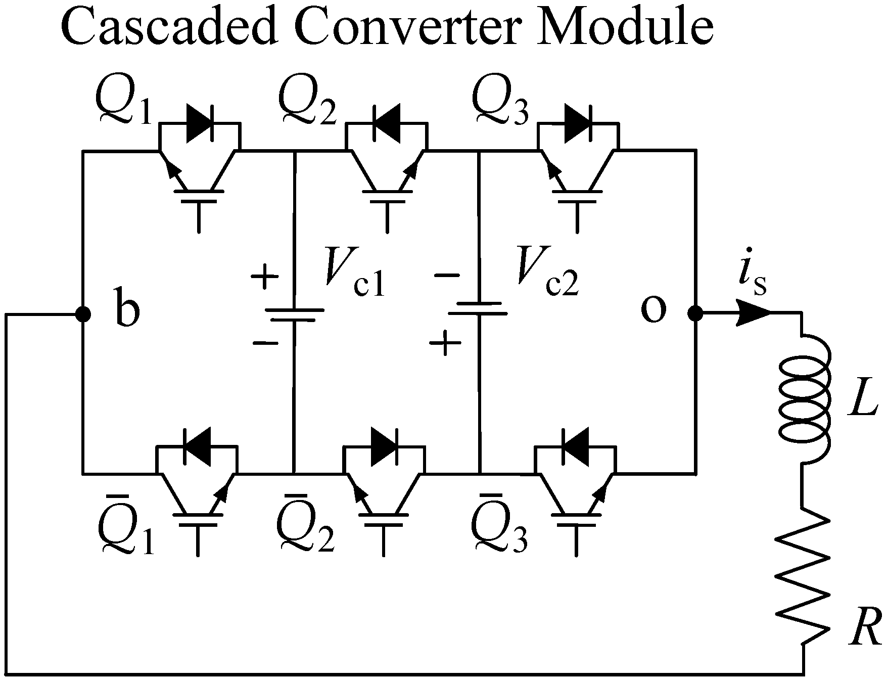
The HMLI topology is based on a series arrangement of a five-level cascaded converter module with the three-level H-bridge converter to form a seven-level converter presented in Figure 3. The five-level cascaded converter module circuit consists of two DC-link capacitors C 1 and C 2 , which are initially charged at V c 1 = V c 2 = V dc , and three pairs of alternately connected active switches ( Q 1 Q ¯ 1 , Q 2 Q ¯ 2 , Q 3 Q ¯ 3 ). The H-bridge converter is comprised of four active switches ( Q a Q d ) (two half bridges), which are connected in parallel with a single DC-bus voltage 2 V dc . In this topology, the fundamental component is generated by the H-bridge converter with the output voltage levels of ±2 V dc and 0. At the same time, the cascaded converter module (CCM) as a series active filter will produce five-level output voltage, namely ±2 V dc , ± V dc , and 0. The combined operation of the HMLI generates a seven-level output voltage. In the HMLI circuit arrangement, the active switches of an H-bridge converter are handling high-voltage stress i.e., double then DC-link capacitors voltage of the CCM.
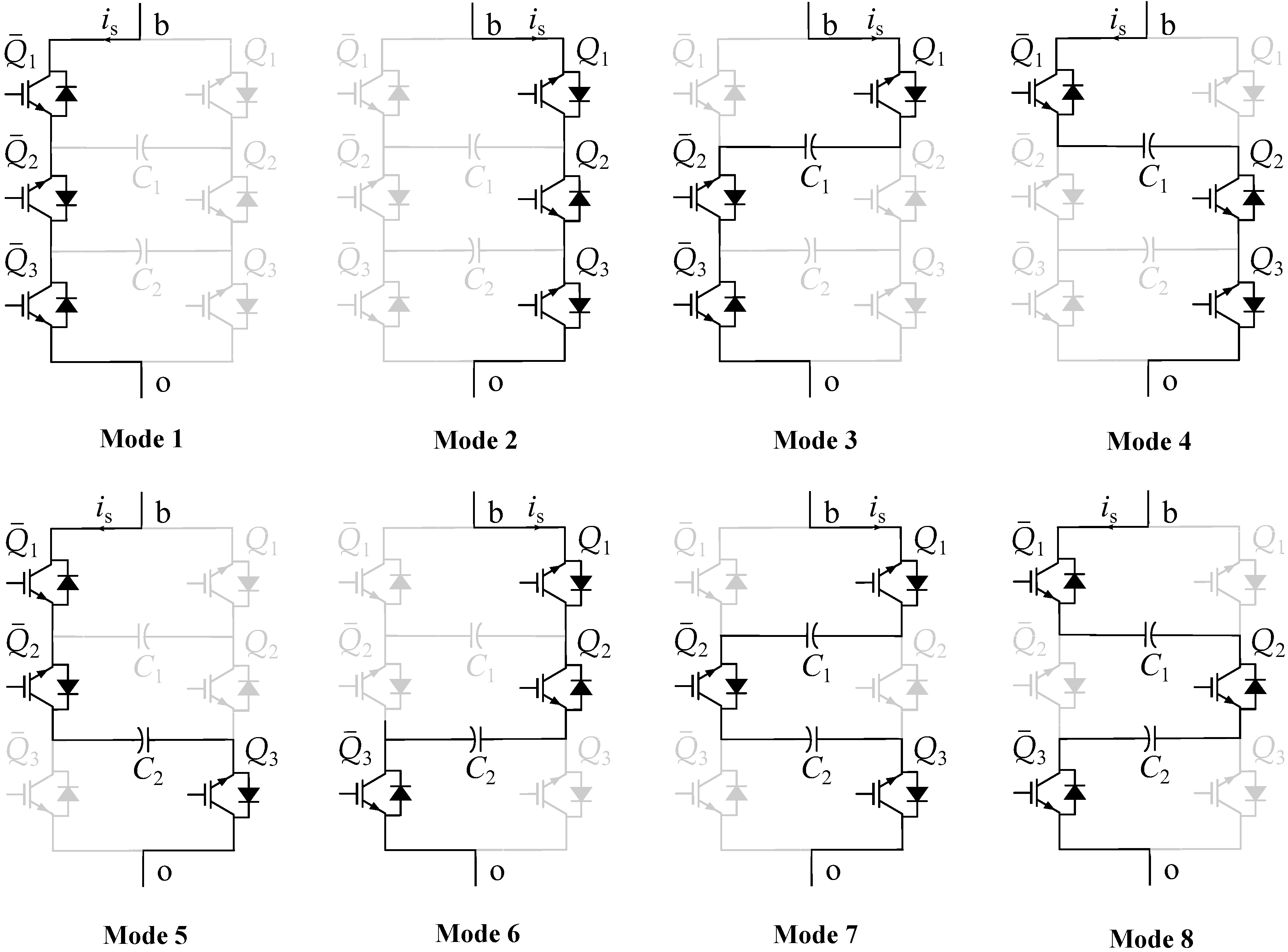
In the HMLI topology, the cascaded converter module is a vital part of circuit topology. It guarantees the seven-level output voltage of the HMLI with minimum harmonic distortion. The five-level output voltage of the cascaded converter module is ensured by the eight distinct switching modes depicted in Figure 4 when the DC-link capacitor voltage is balanced to its reference value. The cascaded converter module has redundancy for output voltage level, namely ± V dc and zero levels, which ensures controllability of the capacitor; however, the ±2 V dc has a unique state. The change in the ±2 V dc is only determined by the direction of the current. As the cascaded converter gives harmonic component support to the HMLI, the DC-link capacitor charge is affected when the power is dissipated across the semiconductor devices during switching to attain the desired output voltage levels. Moreover, the DC-link capacitor voltage also deviates from its reference value when the output terminals are connected through any single capacitor. This happens when the output voltage level ± V dc is achieved; these switching states affect the DC-link capacitor voltage by either charging or discharging it, depending on the converter’s current direction as given in Table 2.

4.1. Hybrid Modulation Strategy

A hybrid modulation strategy is employed to HMLI topology to overcome the high-frequency switching limitation of the MPC control method, as discussed. In this strategy, the converter modules which are under higher voltage stress are operated at the low switching frequency, and switches under low-voltage stress are operated with high switching frequency. Figure 3 shows the seven-level HMLI topology connected to the RL load. The switches in the H-bridge converter are under higher voltage stress; therefore, they are modulated with a switching frequency of 50 Hz. The low switching frequency will help in reducing the switching loss of the H-bridge converter, but it will produce high harmonics. The cascaded converter module is introduced in series connection, which will filter out the high harmonics and enhanced the output voltage levels of the converter. The cascaded converter module switches are under low-voltage stress, while converter operation switching frequency of 1.6 kHz is observed.
The cascaded converter module is controlled by model predictive control (MPC), which optimally predicts the next level, and the decision is injected through the pulse width modulation (PWM) technique. The Fourier series expansion of the output voltage of a seven-level converter topology can be expressed as
v ao ( t ) = v ab ( t ) + v bo ( t )
v ab ( t ) = 4 V dc π n 1 n cos ( n θ ) sin ( n ω t )
v bo ( t ) = v ab ( t ) 4 V dc π cos ( θ ) sin ( ω t )
where n denotes the harmonic order. θ is the firing angle of the fundamental converter, which can be expressed as follows:
θ = arccos π 4 | V cj | V dc j = 1 , 2 .

4.1.1. Prediction Model

The dynamic model of a five-level cascaded converter module (CCM) shown in Figure 5 can be equated as follows
L d i s d t = S l V c 1 + S m V c 2 R i s
where R and L denote the load resistor and inductor, respectively, whereas S l and S m are the switching functions of the converter module, which can be computed as follows:
S l = Q 1 Q ¯ 2 Q ¯ 1 Q 2
S m = Q ¯ 2 Q 3 Q 2 Q ¯ 3
For a given switch-direction, the DC-link capacitors voltage change is the function of converter current direction ( i s ) which are expressed as
d V c 1 d t = S l i s C 1
d V c 2 d t = S m i s C 2
In the finite set model predictive control (FS-MPC) switching mode for each converter level is a direct control action from MPC, and the decision is then injected through PWM. In this case, the response time of MPC control action is dependent on the sampling time of T s .
As the cascaded module provides high switching frequency support, the current control is implemented on this module, which will help to track the current fast and minimize the current ripple. The employed converter current control depends on the output voltage produced by the cascaded converter module. The main objective of this control scheme is to produce the desired voltage for the required output current. To obtain the prediction equations, Euler formula is applied to converter current in Equation (20) which is given as:
I s ( t + T s ) = T s L [ S l V c 1 + S m V c 2 R i s ( t ) ] + i s ( t )

4.1.2. Prediction Control

FS-MPC is comprised of finite control actions. Considering cascaded converter module, it has five current prediction equations, which are expressed as:
I s 1 ( t + T s ) = T s L [ V c 1 R i s ( t ) ] + i s ( t )
I s 2 ( t + T s ) = T s L [ V c 1 + V c 2 R i s ( t ) ] + i s ( t )
I s 3 ( t + T s ) = T s L [ V c 1 R i s ( t ) ] + i s ( t )
I s 4 ( t + T s ) = T s L [ V c 1 V c 2 R i s ( t ) ] + i s ( t )
I s 5 ( t + T s ) = T s L [ R i s ( t ) ] + i s ( t )
A cost function K n is calculated for each predicted current, which corresponds to a distinct voltage level I s n ( t + T s ) as follows
K n = α | I s n ( t + T s ) I ref | f o r n = 1 , 2 , , 5 .
where α denotes the weighting factor, and I ref is the converter reference current. Among the five current control actions, the optimal one is achieved by solving the optimization problem. The optimal voltage level V m is subjected to the least cost function as expressed below.
V m = arg min i s ( t ) K n

4.2. Voltage Balancing of DC Capacitors

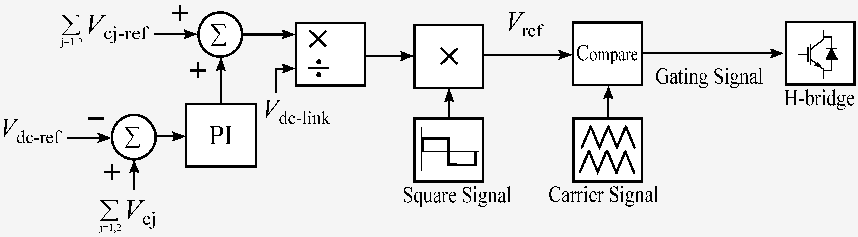
The cascaded module in the circuit arrangement of seven-level provides harmonic and high switching frequency support. Therefore, the current control is implemented in this module. To track the current to its reference, DC-link capacitors need to generate the desired voltage for the required output current. Moreover, the power dissipation across the semiconductor devices during the switching is fed by these capacitors. Therefore, the summated DC-link regulation of the DC-link capacitor is needed to ensure the safe operation of the converter. To maintain the common-mode DC-link voltage to desired voltage level, the H-bridge cell which provides fundamental component support will vary the fundamental component period to provide an amount of energy needed to the cascaded module subject to Equation (19) Figure 6 depicts the common-mode voltage regulation in which the error of the summated DC-link voltage with its reference value is compensated through PI controller and added in the reference common-mode DC-link capacitors voltage to calculate the initial angle of the H-bridge cell. This will vary the modulation signal amplitude according to the energy need to the cascaded converter module and compared further with the carriers signals of 50 Hz to attain the switching signal for the H-bridge cell.
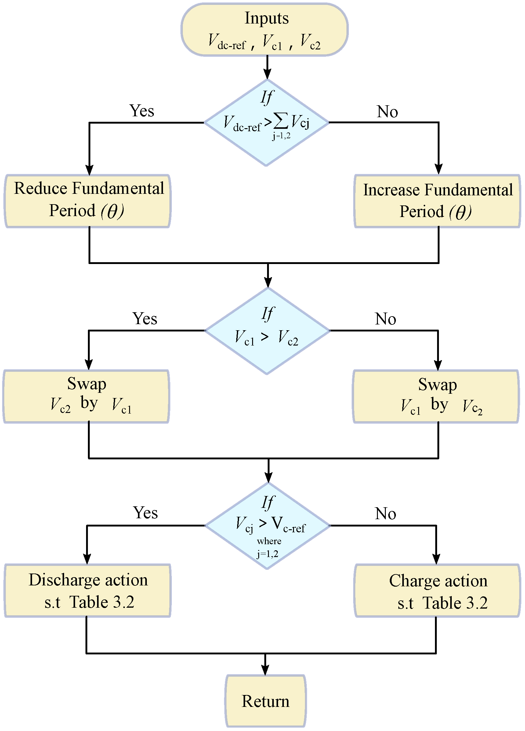
Furthermore, due to parametric variances and switching delays, the individual DC-link capacitor voltage may deviate from its reference DC-value. The charge swapping technique by redundant switching states selection in Figure 4 is used to converge the DC-link capacitors voltage value to its desired reference. In Figure 7, a flow chart demonstrates the voltage control algorithm of the overall converter.

5. Simulation and Experimental Results

The seven-level HMLI configuration shown in 
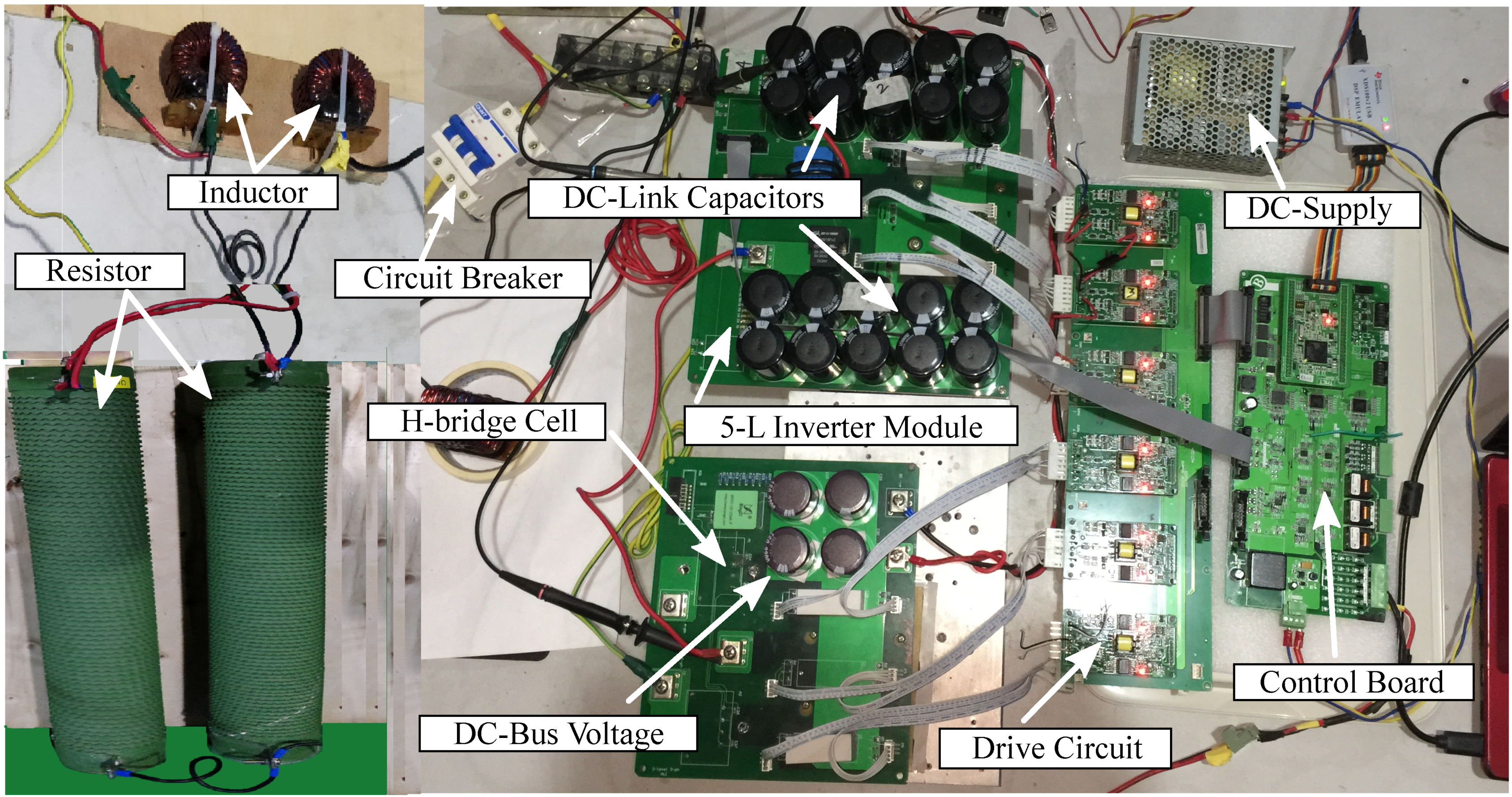
Figure 3 is simulated in MATLAB sim-power environment to demonstrate the system’s effectiveness and performance of the modulation and control scheme. The proposed converter and its control scheme are experimentally validated by a low-voltage laboratory prototype as depicted in Figure 8. The control algorithm is implemented on a customized control board that uses TMS320C28346 DelfinoTM micro-controller unit (MCU), EPM570 ALTERA® complex programmable logic device (CPLD), and AD Conversion to realize the control in practice. To verify the converter system results, simulation results are scaled accordingly to low-voltage laboratory prototype using the system’s parameters listed in Table 3. The selection of all component values is achieved with extensive simulations. The MPC algorithm is employed with a sampling frequency of 12 kHz.
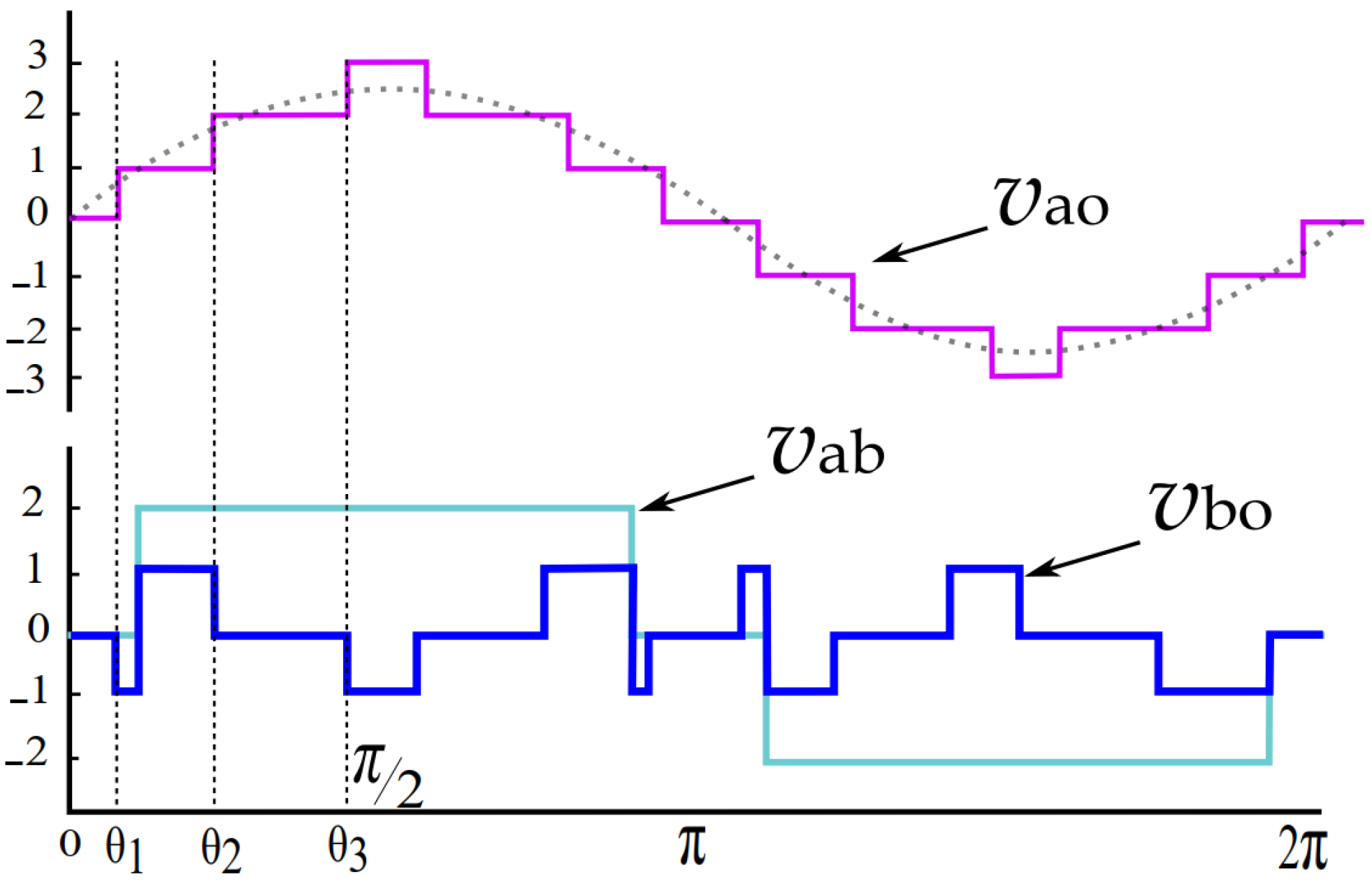
Figure 9 represents the overall output voltage of the HMLI inverter ( v a o ) which is the addition of H-bridge output voltage ( v a b ) and CCM output voltage ( v b o ) and can be equated as given in Equations (16)–(19). Figure 9 depicts the output of seven-level ±3Vdc, ±2Vdc, ±Vdc, and 0, which is achieved by operating the converter modules as per the desired switching states listed in Table 4. The h-bridge converter is connected to 2Vdc and will produce output voltage levels of ±2Vdc and 0, whereas the cascaded converter module (CCM) circuit consists of two DC-link capacitors C1 and C2, which are initially charged at Vc1 = Vc2 = Vdc and will provide harmonic component support.
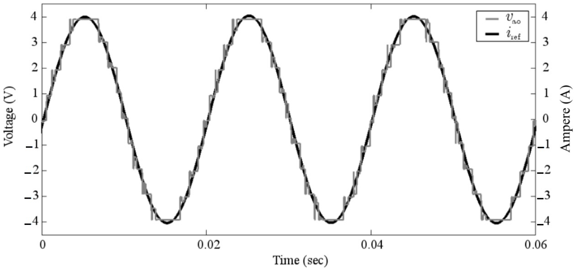
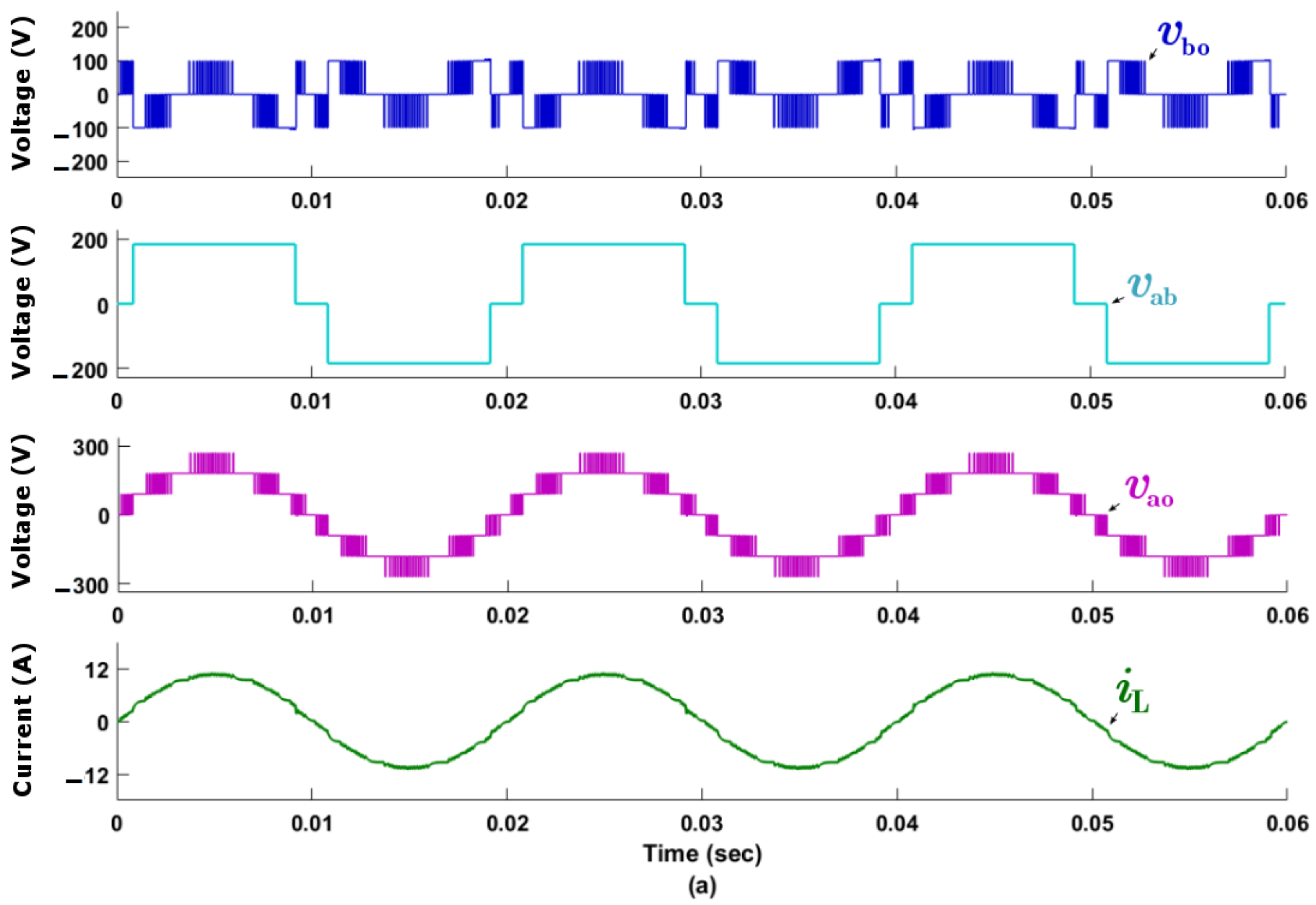
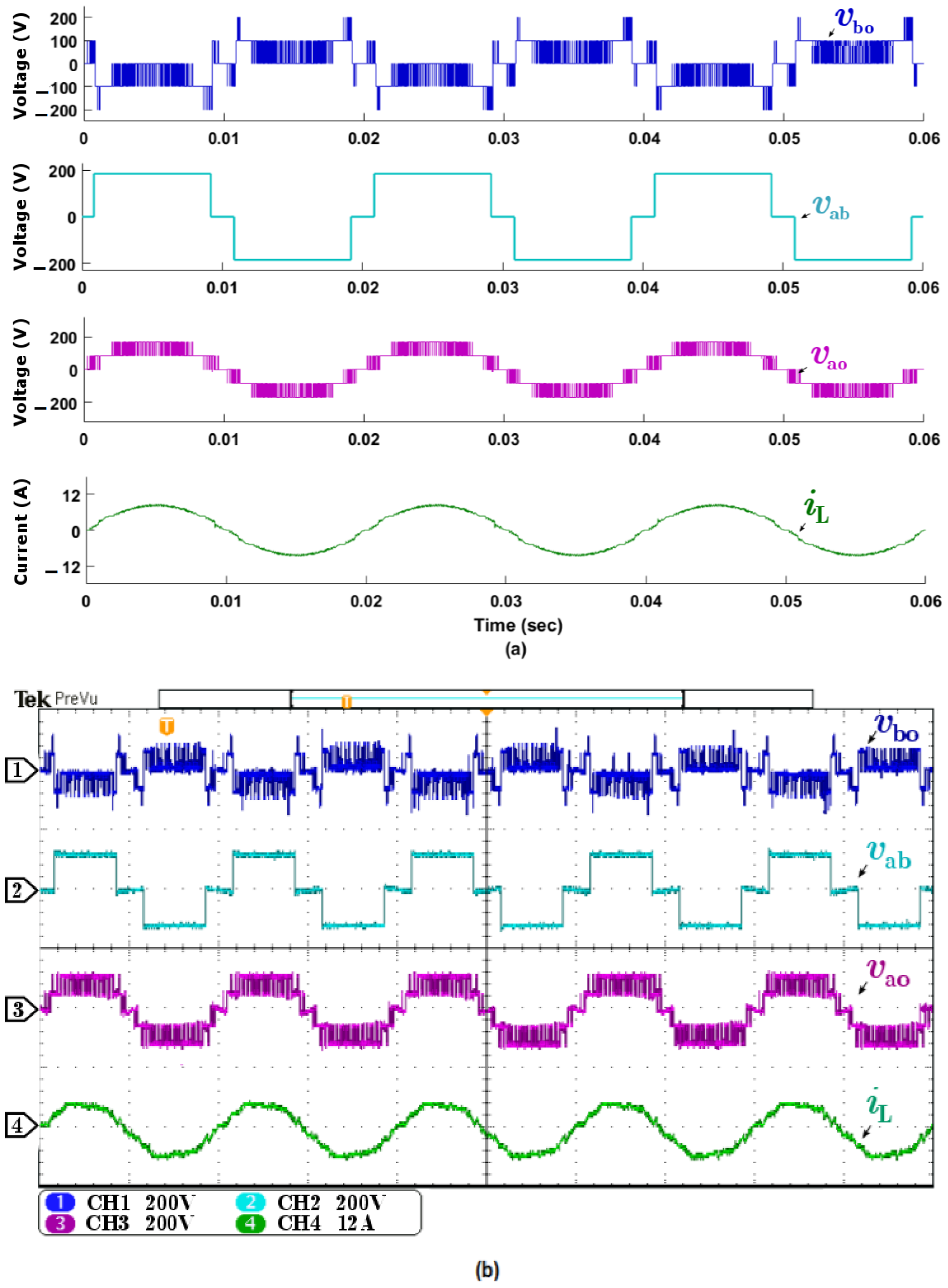
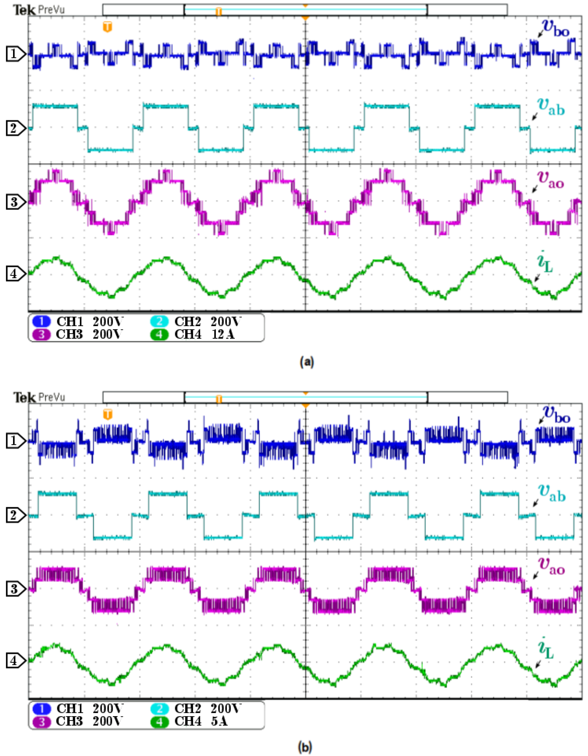
Figure 10 depicts the simulation and experimental results of the seven-level inverter output voltage at maximum modulation index M = 1.1 and converter current waveform for load-A. Figure 10a shows simulation results of individual converter cells and the overall output voltage of the converter. Active power is transferred by an H-bridge cell where high harmonics are compensated through a series active filter (CCM). Figure 10b show experimental results of the inverter, which generates the desired output voltage to track the current to its reference value for load-A. Figure 11 presents the simulation and experimental results of the studied converter, operating at M = 0.9 for load-A, which results in the output voltage of five levels of the converter. Figure 11a shows simulation results of individual converter cell and the overall output voltage of the converter, whereas Figure 11b show experimental results of the inverter, which generates the desired output voltage to track the current to its reference value for load-A. It can be seen in Figure 10 and Figure 11 that when the modulation index is reduced from M = 1.1 to M = 0.9, the distortion in the current waveform gets increased.
Figure 12 depicts the experimental results of the seven-level inverter output voltage at different modulation indexes and inverter current waveform for load-B. Figure 12a shows experimental results of the inverter which generates the desired output voltage to track the current to its reference value for load-B at M = 1.1, whereas, Figure 12b show experimental results of the inverter which generates the desired output voltage to track the current to its reference value for load-B at M = 0.9.
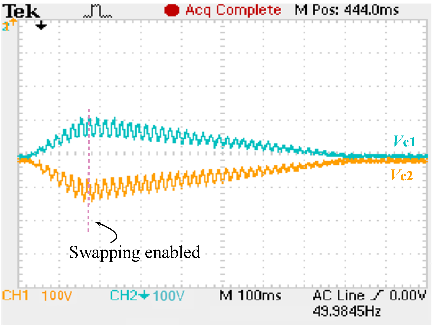
Figure 13 shows experimental validation of the voltage control. The common-mode DC-link capacitors voltage is regulated to its reference value with the modification of fundamental component duty cycle subject to Figure 7. Once the common-mode voltage is regulated, the individual DC-link capacitor voltage deviates from its reference value due to the parametric variance and switching delay. To converge the individual capacitor to its reference value, the redundant states are used to swap the capacitor charge among each other, which can be seen in 
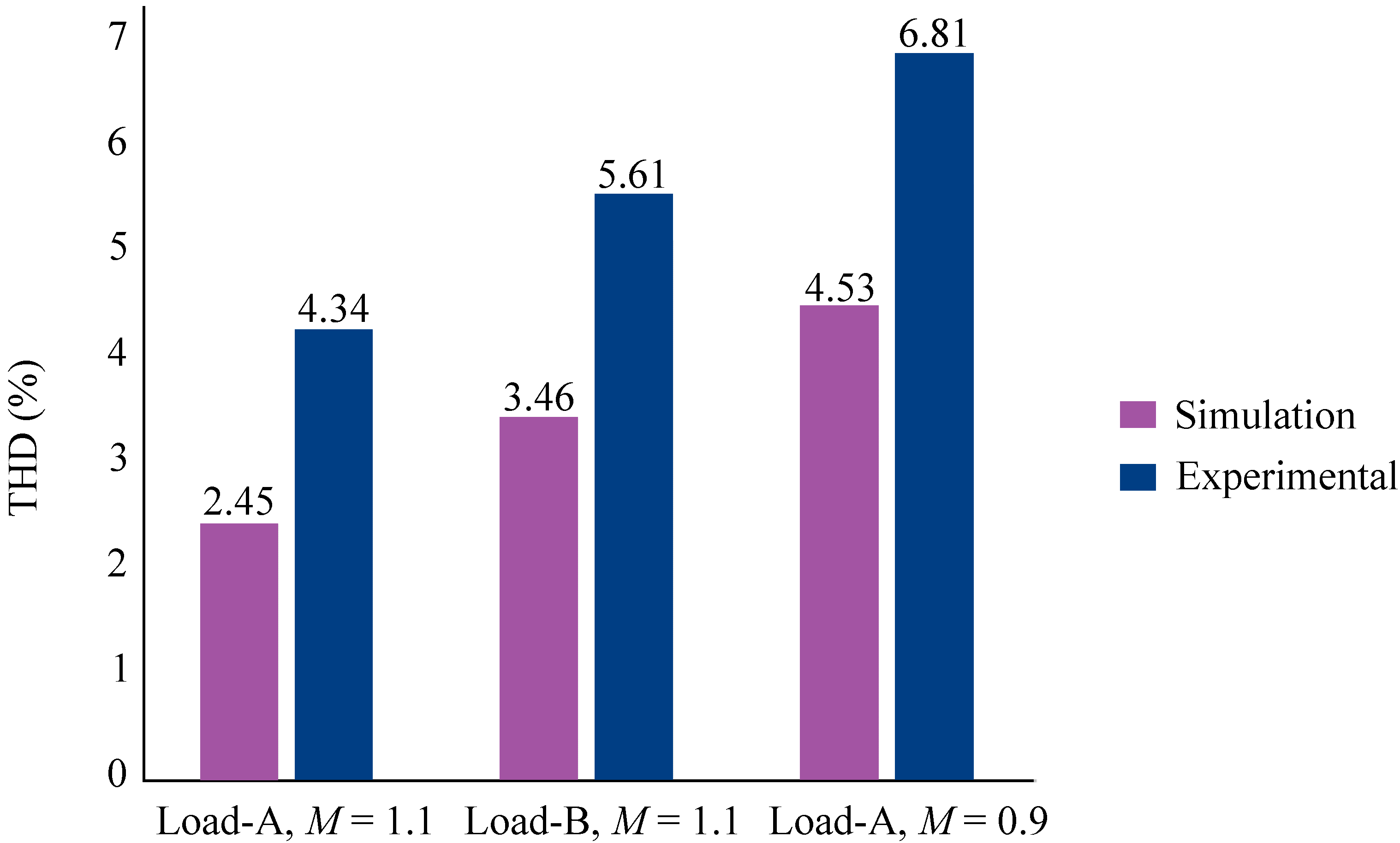
Figure 13. The converter performance is tested for three cases implemented in simulation and on laboratory prototype, and their respective satisfactory THD results are presented in Figure 14. The THD estimations by Fast Fourier Transform (FFT) is shown for three different cases with a simulation THD of 2.45% for load-A at M = 1.1, 3.46% for load-B at M = 1.1, and 4.53% for load-A at M = 0.9. However, the experimental THD of 4.34% for load-A at M = 1.1, 5.61% for load-B at M = 1.1, and 6.81% for load-A at M = 0.9 is achieved. The simulation THD is comparatively lowered than that of experimental THD because of the losses and noise.
The proposed HMLI topology is compared with existing topologies such as NPC [1], HNPC with H-bridge [2], HNPC with cascaded module [3] in terms of current THD operating at different power ratings (25%, 50%, 100%). The existing topologies, NPC, HNPC with H-bridge, HNPC with cascaded module, and proposed HMLI topology at a 25% power rating have current THD of 6.59, 6.71, 5.31, and 6.55, respectively. Similarly, at 50% power rating have current THD of 2.83, 3.43, 3.39, and 3.31, respectively, likewise, at 100% power rating current THD of 1.38, 1.73, 1.71, and 1.66 are achieved, respectively. The proposed HMLI topology is compared with NPC-VSC [1] in terms of efficiency operating at different power ratings (25%, 50%, and 100%). The proposed HMLI topology has 98.2% efficiency when operating at a 25% power rating. In contrast, the NPC-VSC has 96.7% efficiency when operating at a 25% power rating. Similarly, when operating with 50% and 100% power rating the efficiency of the proposed HMLI and existing NPC-VSC have 99.2% and 98.7%, 99.5%, and 99.1%, respectively. Thus, it is concluded that the proposed topology has superior performance compared to the exiting topologies in terms of current THD and efficiency.

6. Conclusions

This paper presents the circuit configuration, control methods, simulation and experimental validation of the proposed HMLI topology. The converter topology is the series arrangement of the H-bridge converter and cascaded converter module. It offers several benefits in terms of low switching loss, higher efficiency, and better current THD. Initially, a finite set model predictive control (FS-MPC) was theoretically analyzed as a switching technique for HMLI. The advantages of using the FS-MPC method employed to HMLI are related to more output voltage levels and low current THD. However, the high switching frequency operation of the high-voltage stressed switches is restricted uses for the proposed lower-medium voltage converter (3–5 KV). To minimize the high switching loss, the HMLI topology modules switches are used to the high-voltage and low-voltage stressed modules, and a hybrid control scheme which is the variant of the MPC method, was proposed. This method is computationally efficient and therefore employed to the proposed topology to minimize the switching efforts of the converter. Moreover, the DC-link capacitor voltage is regulated to its reference value for stable converter operation. The performance and effectiveness of single-phase HMLI and a hybrid control scheme has been validated through simulations and experimental results using a low-voltage laboratory prototype. The main findings of this research work are that a new hybrid control scheme has been successfully implemented on HMLI topology, which significantly improves efficiency at different loading conditions and reduces current THD when compared with existing techniques.

Author Contributions

Conceptualization, M.A. and A.F.; data curation, M.A.; formal analysis, M.A. and G.H.; funding acquisition, L.M.-P.; investigation, A.F.; methodology, M.A. and Z.S.; project administration, F.A., M.U. and L.M.-P.; resources, M.A.; software, G.H. and Z.S.; supervision, M.U. and L.M.-P.; validation, G.H. and F.A.; visualization, G.H., A.F. and F.A.; writing—original draft, M.A., G.H.; writing—review and editing, A.F., Z.S. and M.U. All authors have read and agreed to the published version of the manuscript.

Funding

This research was funded by Faculty of Electrical Engineering, Ostfold University College, 1757 Halden, Norway.

Conflicts of Interest

The authors declare no conflict of interest.

References

  1. Ali, M.; Khan, M.M.; Xu, J.; Faiz, M.T.; Ali, Y.; Hashmi, K.; Tang, H. Series Active Filter Design Based on Asymmetric Hybrid Modular Multilevel Converter for Traction System. Electronics 2018, 7, 134. [Google Scholar] [CrossRef] [Green Version]
  2. Feng, J.; Chu, W.Q.; Zhang, Z.; Zhu, Z.Q. Power electronic transformer-based railway traction systems: Challenges and opportunities. IEEE J. Emerg. Sel. Top. Power Electron. 2017, 5, 1237–1253. [Google Scholar] [CrossRef]
  3. Pulikanti, S.R.; Konstantinou, G.; Agelidis, V.G. Hybrid seven-level cascaded active neutral-point-clamped-based multilevel converter under SHE-PWM. IEEE Trans. Ind. Electron. 2012, 60, 4794–4804. [Google Scholar] [CrossRef]
  4. Ren, L.; Gong, C.; He, K.; Zhao, Y. Modified hybrid modulation scheme with even switch thermal distribution for H-bridge hybrid cascaded inverters. IET Power Electron. 2017, 10, 261–268. [Google Scholar] [CrossRef]
  5. Cecati, C.; Dell’Aquila, A.; Liserre, M.; Monopoli, V.G. A passivity-based multilevel active rectifier with adaptive compensation for traction applications. IEEE Trans. Ind. Appl. 2003, 39, 1404–1413. [Google Scholar] [CrossRef]
  6. Chauhan, N.; Jana, K.C. Cascaded multilevel inverter for underground traction drives. In Proceedings of the 2012 IEEE International Conference on Power Electronics, Drives and Energy Systems (PEDES), Bengaluru, India, 16–19 December 2012; pp. 1–5. [Google Scholar]
  7. McGrath, B.P.; Holmes, D.G. Multicarrier PWM strategies for multilevel inverters. IEEE Trans. Ind. Electron. 2002, 49, 858–867. [Google Scholar] [CrossRef]
  8. Konstantinou, G.; Capella, G.J.; Pou, J.; Ceballos, S. Single-carrier phase-disposition PWM techniques for multiple interleaved voltage-source converter legs. IEEE Trans. Ind. Electron. 2017, 65, 4466–4474. [Google Scholar] [CrossRef] [Green Version]
  9. Trabelsi, M.; Bayhan, S.; Ghazi, K.A.; Abu-Rub, H.; Ben-Brahim, L. Finite-control-set model predictive control for grid-connected packed-U-cells multilevel inverter. IEEE Trans. Ind. Electron. 2016, 63, 7286–7295. [Google Scholar] [CrossRef]
  10. Bayhan, S.; Trabelsi, M.; Abu-Rub, H.; Malinowski, M. Finite-control-set model-predictive control for a quasi-Z-source four-leg inverter under unbalanced load condition. IEEE Trans. Ind. Electron. 2016, 64, 2560–2569. [Google Scholar] [CrossRef]
  11. Tamim, T.M.; Li, S.; Wu, J. Multi-level model predictive controller with satisfactory optimization for multi-level converters. Simul. Model. Pract. Theory 2019, 92, 1–16. [Google Scholar] [CrossRef]
  12. Shadmand, M.B.; Mosa, M.; Balog, R.S.; Rub, H.A. Maximum power point tracking of grid connected photovoltaic system employing model predictive control. In Proceedings of the 2015 IEEE Applied Power Electronics Conference and Exposition (APEC), Charlotte, NC, USA, 15–19 March 2015; pp. 3067–3074. [Google Scholar]
  13. Mhiesan, H.; Wei, Y.; Siwakoti, Y.P.; Mantooth, H.A. A Fault-tolerant hybrid cascaded h-bridge multilevel inverter. IEEE Trans. Power Electron. 2020, 35, 12702–12715. [Google Scholar] [CrossRef]
  14. Liu, X.; Wang, D.; Peng, Z. Improved finite-control-set model predictive control for active front-end rectifiers with simplified computational approach and on-line parameter identification. ISA Trans. 2017, 69, 51–64. [Google Scholar] [CrossRef] [PubMed]
  15. Liu, X.; Wang, D.; Peng, Z. An improved finite control-set model predictive control for nested neutral point-clamped converters under both balanced and unbalanced grid conditions. Int. J. Electr. Power Energy Syst. 2019, 104, 910–923. [Google Scholar] [CrossRef]
  16. Taheri, A.; Zhalebaghi, M.H. A new model predictive control algorithm by reducing the computing time of cost function minimization for NPC inverter in three-phase power grids. ISA Trans. 2017, 71, 391–402. [Google Scholar] [CrossRef] [PubMed]
  17. Bagheri, F.; Komurcugil, H.; Bayhan, S. An Effective Double Frequency Ripple Suppression Based on Sliding-Mode Control for Cascaded Multilevel Quasi-Z-Source Inverters. In Proceedings of the 2020 IEEE 29th International Symposium on Industrial Electronics (ISIE), Delft, The Netherlands, 17–19 June 2020; pp. 636–641. [Google Scholar]
  18. Gupta, R.; Ghosh, A.; Joshi, A. Multiband hysteresis modulation and switching characterization for sliding-mode-controlled cascaded multilevel inverter. IEEE Trans. Ind. Electron. 2009, 57, 2344–2353. [Google Scholar] [CrossRef]
  19. Kumar, N.; Saha, T.K.; Dey, J. Sliding-mode control of PWM dual inverter-based grid-connected PV system: Modeling and performance analysis. IEEE J. Emerg. Sel. Top. Power Electron. 2015, 4, 435–444. [Google Scholar] [CrossRef]
  20. Kumar, N.; Saha, T.K.; Dey, J. Sliding mode control, implementation and performance analysis of standalone PV fed dual inverter. Sol. Energy 2017, 155, 1178–1187. [Google Scholar] [CrossRef]
  21. Ye, Y.; Hua, T.; Chen, S.; Wang, X. Neutral-Point-Clamped Five-Level Inverter with Self-Balanced Switched-Capacitor. IEEE Trans. Ind. Electron. 2021. [Google Scholar] [CrossRef]
  22. Chaudhury, A.; Sonti, V.; Hota, A.; Saxena, A.R.; Jain, S. A New Single-Phase Five-Level Neutral Point Clamped Cascaded Multilevel Inverter for Minimization of Leakage Current in PV Systems. In Proceedings of the 2021 International Conference on Sustainable Energy and Future Electric Transportation (SEFET), Hyderabad, India, 21–23 January 2021; pp. 1–5. [Google Scholar]
  23. Jiang, L.; Xiao, F.; Hu, L.; Jia, Y. SVPWM algorithm for five-level active-neutral-point-clamped H-bridge inverters. J. Power Electron. 2021, 1–12. [Google Scholar] [CrossRef]
  24. Ye, Y.; Zhang, G.; Huang, J.; Chen, S.; Wang, X. Comparative Analysis of Hybrid NPP and NPC Seven-Level Inverter with Switched-Capacitor. IEEE Access 2021. [Google Scholar] [CrossRef]
  25. Miremad, A.; Monfared, K.K.; Iman-Eini, H.; Neyshabouri, Y. Design and control of a STATCOM based on hybrid cascaded H-bridge and full-bridge neutral point clamped multilevel inverter. IET Power Electron. 2020, 13, 4019–4030. [Google Scholar] [CrossRef]
  26. Pamujula, M.; Ohja, A.; Swarnkar, P.; Kulkarni, R.D.; Mittal, A. A Novel Cascaded ‘H’Bridge-Based Multilevel Inverter with Reduced Losses and Minimum THD. In Advances in Clean Energy Technologies; Springer: Singapore, 2021; pp. 627–639. [Google Scholar]
  27. Capella, G.J.; Pou, J.; Ceballos, S.; Konstantinou, G.; Zaragoza, J.; Agelidis, V.G. Enhanced phase-shifted PWM carrier disposition for interleaved voltage-source inverters. IEEE Trans. Power Electron. 2014, 30, 1121–1125. [Google Scholar] [CrossRef] [Green Version]
Figure 1. HMLI topology connected to RL load.
Energies 14 04563 g001
Figure 2. Nine-level inverter output voltage.
Energies 14 04563 g002
Figure 3. Seven-level inverter topology.
Energies 14 04563 g003
Figure 4. Switching modes of cascaded converter module.
Energies 14 04563 g004
Figure 5. Five-level converter topology.
Energies 14 04563 g005
Figure 6. Common-mode voltage regulation.
Energies 14 04563 g006
Figure 7. DC-link capacitor voltage balancing algorithm.
Energies 14 04563 g007
Figure 8. Experimental setup.
Energies 14 04563 g008
Figure 9. Output voltage of the proposed HMLI topology, Overall output voltage of the inverter ( v a o ), H-bridge output voltage ( v a b ) and CCM output voltage ( v b o ).
Energies 14 04563 g009
Figure 10. Output voltage of inverter topology for load-A at M = 1.1, (a) simulation waveform of respective converter modules and inverter current, (b) experimental waveform of respective converter modules and inverter current, traces channel 1, 2, 3 (200 V/div) and 4 (12 A/div).
Energies 14 04563 g010aEnergies 14 04563 g010b
Figure 11. Output voltage of inverter topology for load-A at M = 0.9, (a) simulation waveform of respective converter modules and inverter current, (b) experimental waveform of respective converter modules and inverter current, traces channel 1, 2, 3 (200 V/div) and 4 (12 A/div).
Energies 14 04563 g011
Figure 12. Experimental waveform of respective converter modules and inverter current at load-B, (a) when M = 1.1, traces channel 1, 2, 3 (200 V/div) and 4 (5 A/div), (b) when M = 0.9, traces channel 1, 2, 3 (200 V/div) and 4 (5 A/div).
Energies 14 04563 g012
Figure 13. Balanced DC-link capacitor voltage, traces channel 1 and 2 (100 V/div).
Energies 14 04563 g013
Figure 14. Inverter current THD at different load.
Energies 14 04563 g014
Table 1. Switching States of HMLI topology connected to RL load.
Switching State Q c Q a Q 1 Q 2 Q 3 v ao
1111110
2110000
3001110
4000000
5011010
6100100
700001 V dc
811100 V dc
911001 V dc
1000100 V dc
11100113 V dc
12101103 V dc
13101112 V dc
14100002 V dc
15111012 V dc
16001012 V dc
1710100 3 V dc
1810001 3 V dc
19101014 V dc
2011110 V dc
2100011 V dc
2200110 V dc
2311011 V dc
2401100 3 V dc
2501001 3 V dc
2601000 2 V dc
2701111 2 V dc
2800010 2 V dc
2911010 2 V dc
3001011 V dc
3101110 V dc
3201010 4 V dc
Table 2. Effect on DC-Link Capacitor.
Switch ModeEffect on Capacitor
When i s is from (o→a)When i s is from (a→o)
C 1 C 2 C 1 C 2
Mode 3Chargeby-passDischargeby-pass
Mode 4Dischargeby-passChargeby-pass
Mode 5by-passChargeby-passDischarge
Mode 6by-passDischargeby-passCharge
Mode 7ChargeChargeDischargeDischarge
Mode 8DischargeDischargeChargeCharge
Table 3. System Parameters of Seven-Level Inverter.
ParameterValue
DC-link capacitor20 μF
CCM carrier frequency3.2 kHz
Capacitor voltage50 V
DC-bus voltage100 V
Load-AR = 44 Ω , L = 2.4 mH
Load-BR = 22 Ω , L = 2.4 mH
Table 4. Seven-level HMLI output voltage.
Angle v ab v bo v ao = ( v ab ) + ( v bo )
0 θ α 1 000
α 1 θ α 2 0 V d c V d c
α 1 θ α 2 2 V d c V d c V d c
α 2 θ α 3 2 V d c 0 2 V d c
α 3 θ π 2 V d c V d c 3 V d c
Publisher’s Note: MDPI stays neutral with regard to jurisdictional claims in published maps and institutional affiliations.

