
Overview of Control Algorithm Verification Methods in Power Electronics Systems


Abstract
: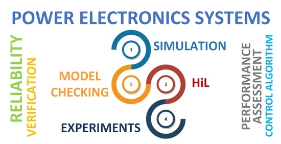
1. Introduction
- (1)
- Presentation of the commonly used verification methods of power electronic systems: simulations and experiments;
- (2)
- Discussion of the recent advancements of introducing formal verification methods to power electronic systems;
- (3)
- Presentation of the use of statistical model checking to automatically check the performance and reliability of a designed power electronic system;
- (4)
- Comparison of the verification methods of power electronics systems.
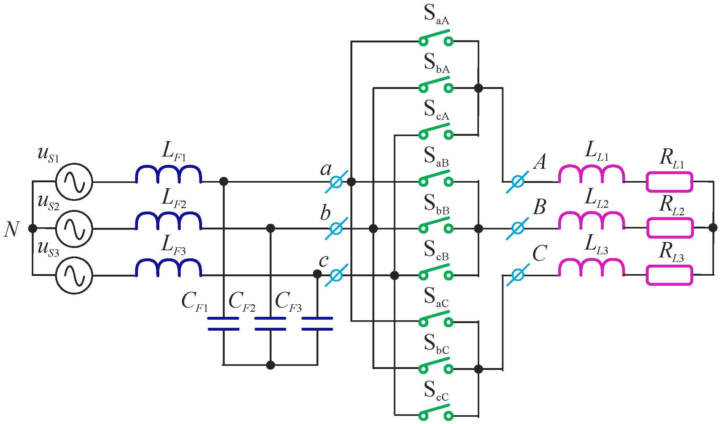
2. System Model
- Ai = [0 1/Cf; −1/Lf − (Rf)/Lf]; Bi = [0 −1/Cf; 1/Lf 0]; Ci = [1 0; 0 1]; Di = [0 0; 0 0];
- system = ss (Ai,Bi,Ci,Di); systemd = c2d (system,Ts);
- Ad11 = systemd.a (1,1); Ad12 = systemd.a (1,2); Ad21 = systemd.a (2,1); Ad22 = systemd.a (2,2);
- Bd11 = systemd.b (1,1); Bd12 = systemd.b (1,2); Bd21 = systemd.b (2,1); Bd22 = systemd.b (2,2);
3. Simulation and Low-Power Prototype Verification of Power Electronic Converter Properties
3.1. General Characteristics of Selected Programs for Simulating Power Electronics Systems
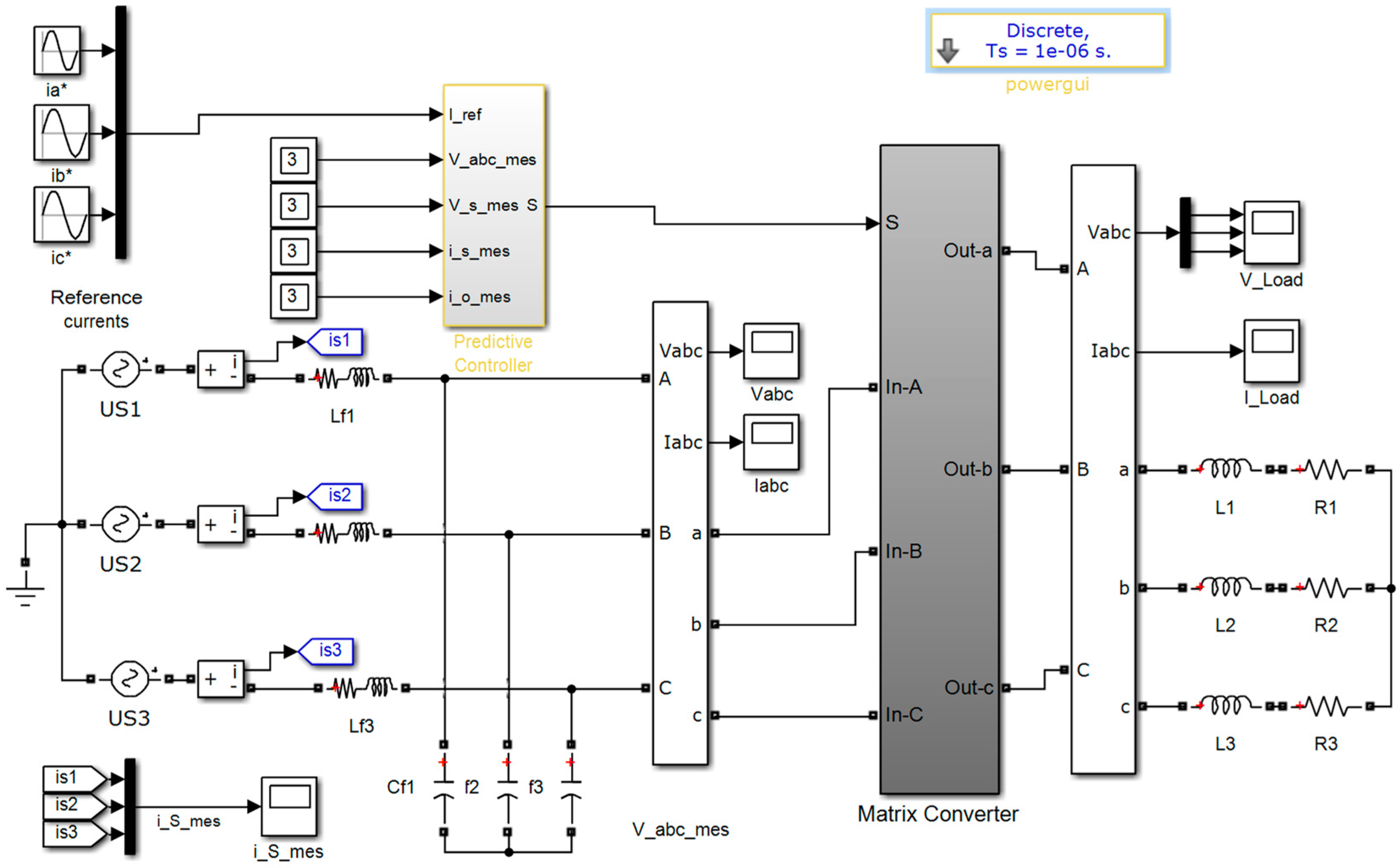
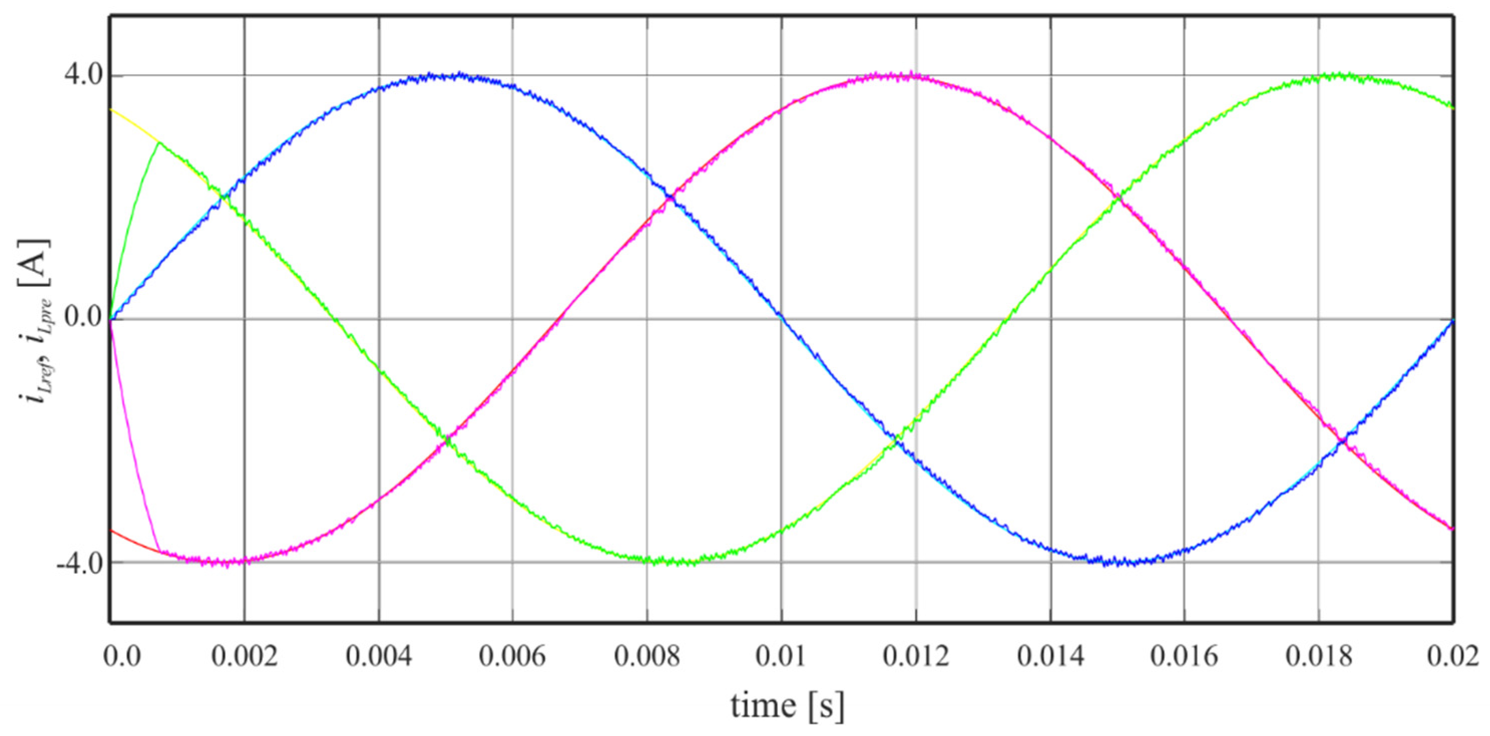
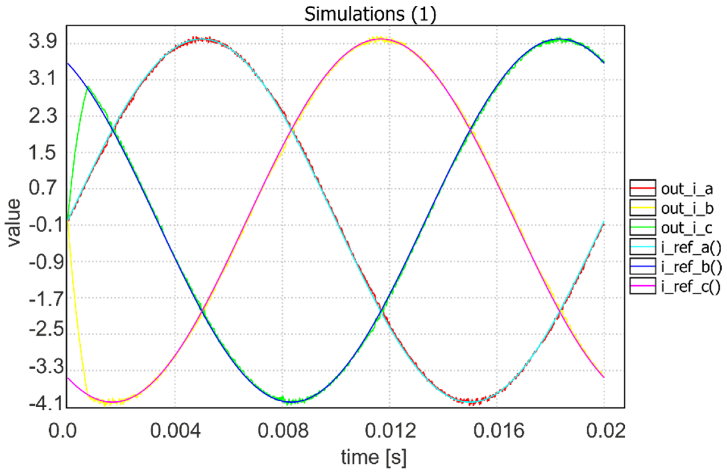
3.2. Simulation of Matrix Converter Using Matlab Simulink
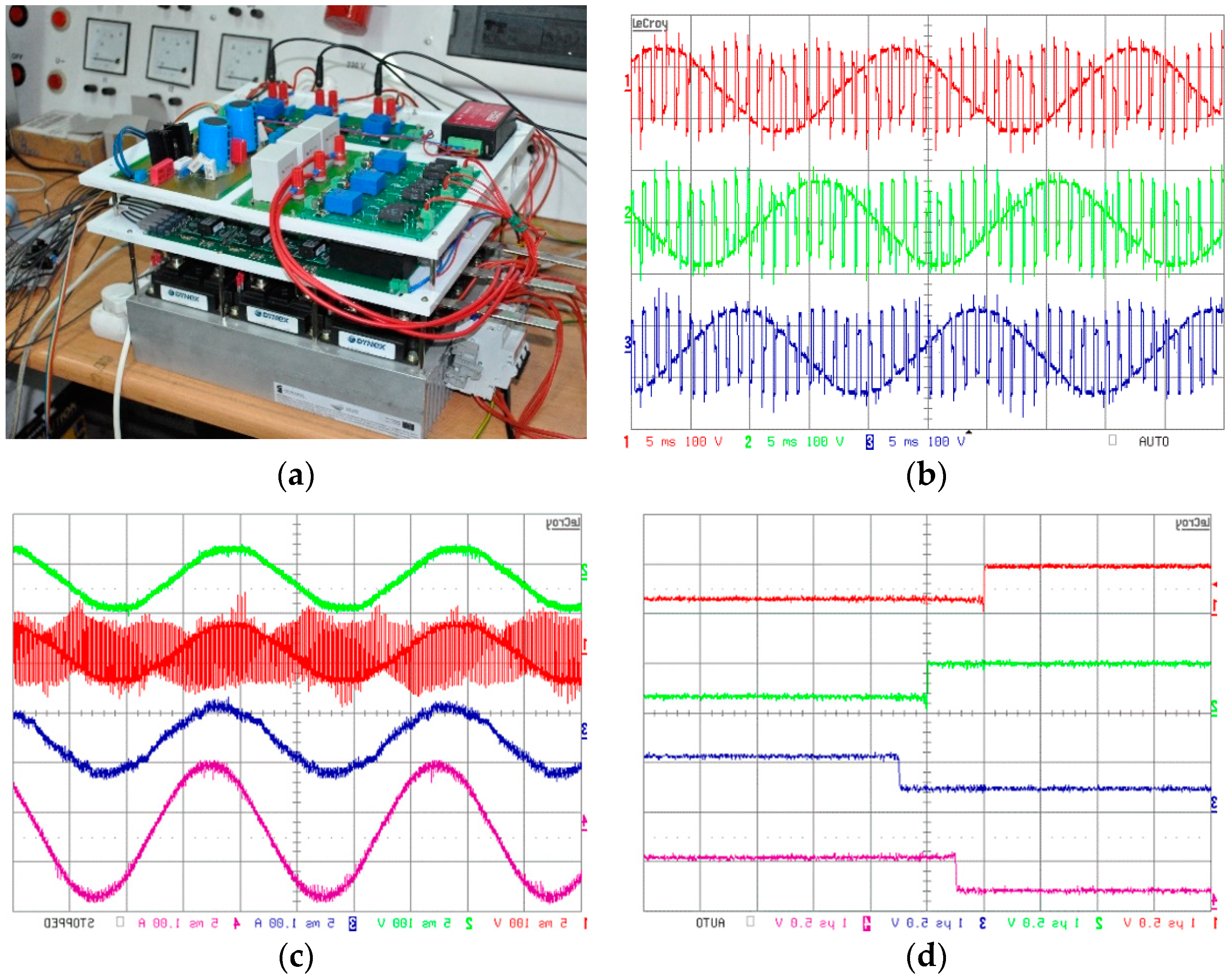
3.3. Low-Power Prototype Experimental Verification
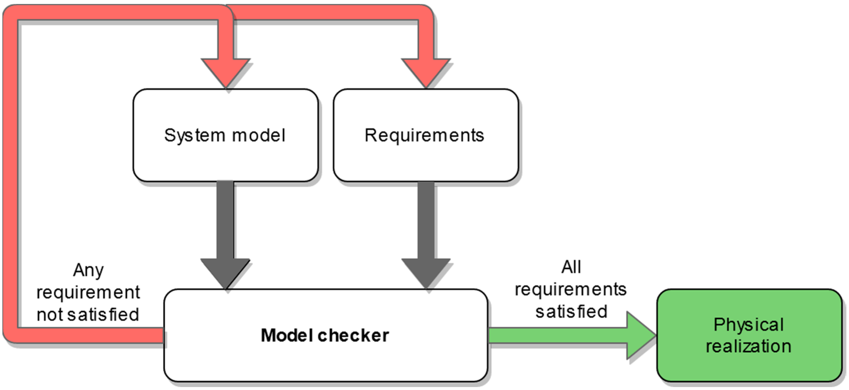
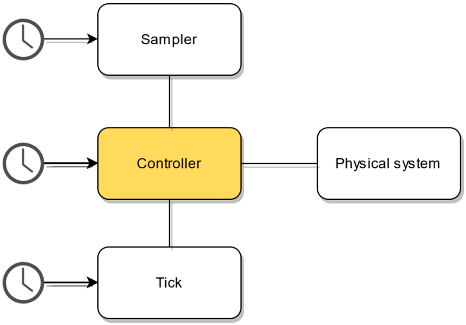
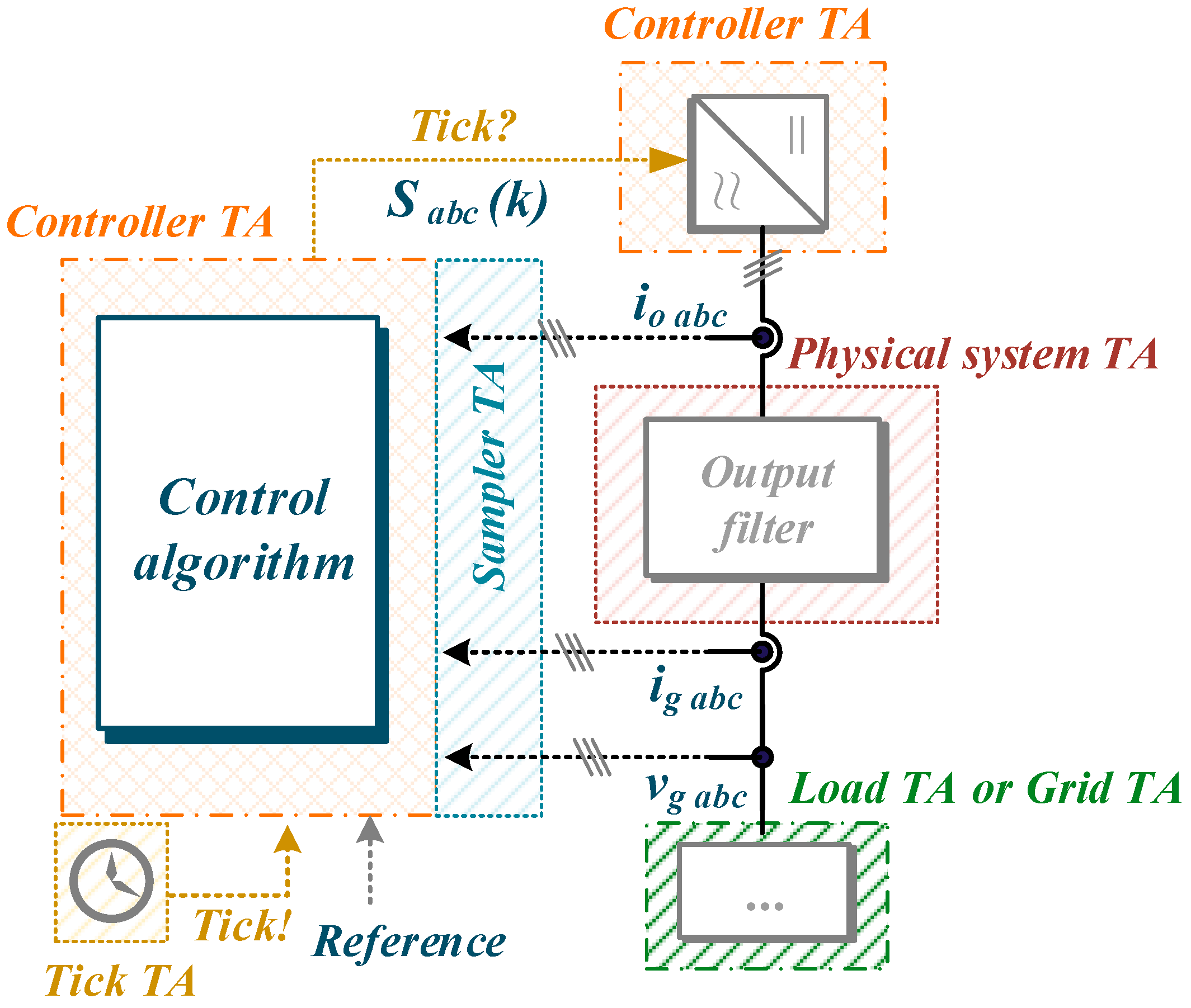
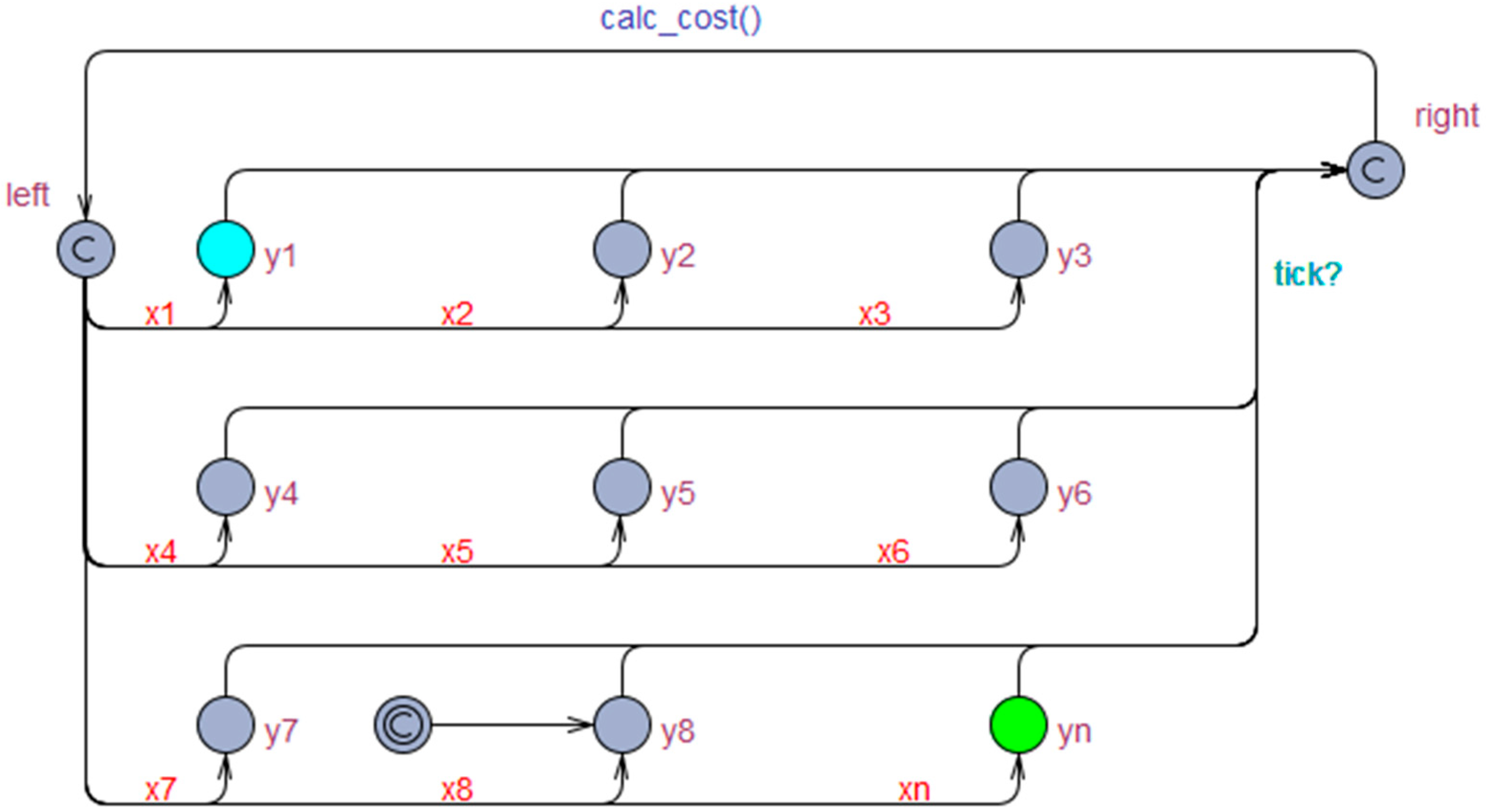
4. Model Checking
4.1. Symbolic Model Checking
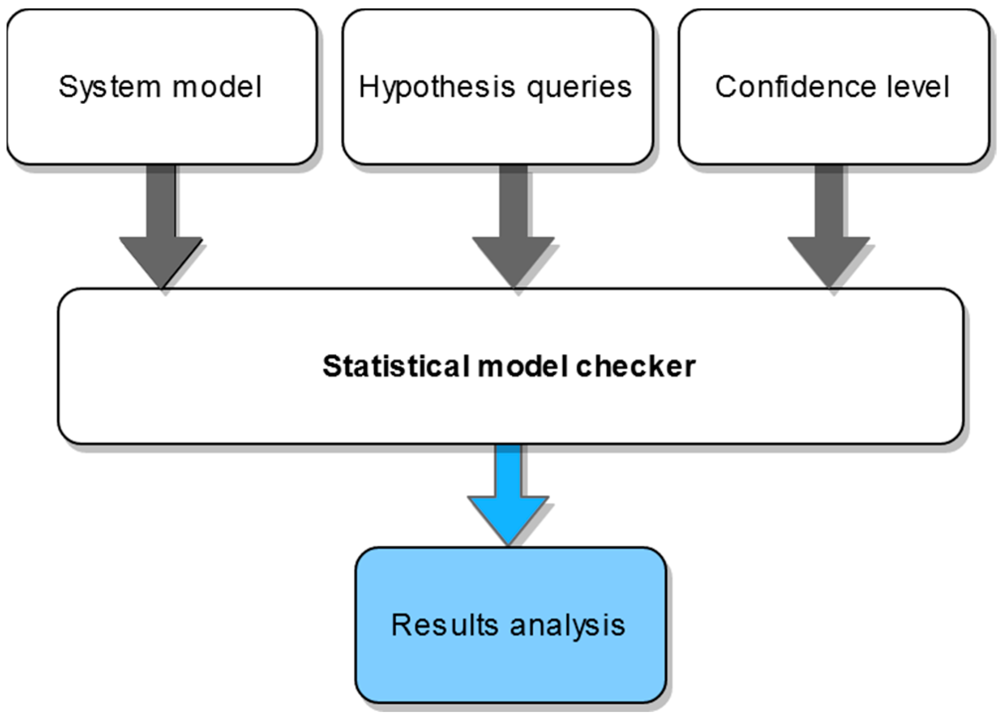
4.2. Statistical Model Checking
5. Comparison of Verification Methods of Power Electronics Systems
6. Control Algorithm Verification Workflow
7. Conclusions
Author Contributions
Funding
Data Availability Statement
Conflicts of Interest
References
- Rashid, M.H. Power Electronics Handbook, 4th ed.; Butterworth-Heinemann: Oxford, UK, 2018. [Google Scholar]
- Manias, S. Simulation of power electronics circuits using Psim, Pspice or Matlab/Simulink. Independently published. 2020. [Google Scholar]
- Le-Huy, H.; Sybille, G. MATLAB/Simulink and PSPice as modelling tools for power systems and power electronics. In Proceedings of the Power Engineering Society Summer Meeting (Cat. No.00CH37134), Seattle, WA, USA, 16–20 July 2000; Volume 2, pp. 766–767. [Google Scholar] [CrossRef]
- Narayanaswamy, P.R.I. Power Electronic Converters: Interactive Modelling Using Simulink; CRC Press: Boca Raton, FL, USA, 2018. [Google Scholar]
- Asadi, F.; Eguchi, K. Simulation of Power Electronics Converters Using PLECS®; Academic Press: Cambridge, MA, USA, 2020. [Google Scholar]
- Drofenik, U.; Cottet, D.; Müsing, A.; Kolar, J.W. Design Tools for Power Electronics: Trends and Innovations. In Proceedings of the 2nd International Conference on Automotive Power Electronics (APE’07), Paris, France, 26–27 September 2008. [Google Scholar]
- Li, F.; Wang, Y.; Wu, F.; Huang, Y.; Liu, Y.; Zhang, X.; Ma, M. Review of Real-time Simulation of Power Electronics. J. Mod. Power Syst. Clean Energy 2020, 8, 796–808. [Google Scholar] [CrossRef]
- Lauss, G.F.; Faruque, M.O.; Schoder, K.; Dufour, C.; Viehweider, A.; Langston, J. Characteristics and Design of Power Hardware-in-the-Loop Simulations for Electrical Power Systems. IEEE Trans. Ind. Electron. 2016, 63, 406–417. [Google Scholar] [CrossRef]
- Mather, B.A.; Kromer, M.A.; Casey, L. Advanced photovoltaic inverter functionality verification using 500 kw power hardware-in-loop (PSIL) complete system laboratory testing. In Proceedings of the 2013 IEEE PES Innovative Smart Grid Technologies Conference (ISGT), São Paulo, Brazil, 6–9 October 2013; pp. 1–6. [Google Scholar] [CrossRef]
- Ibarra, L.; Rosales, A.; Ponce, P.; Molina, A.; Ayyanar, R. Overview of Real-Time Simulation as a Supporting Effort to Smart-Grid Attainment. Energies 2017, 10, 817. [Google Scholar] [CrossRef] [Green Version]
- Faruque, M.D.O.; Strasser, T.; Lauss, G.; Jalili-Marandi, V.; Forsyth, P.; Dufour, C.; Dinavahi, V.; Monti, A.; Kotsampopoulos, P.; Martinez, J.A.; et al. Real-time simulation technologies for power systems design, testing, and analysis. IEEE Power Energy Technol. Syst. J. 2015, 2, 63–73. [Google Scholar] [CrossRef]
- Official Website of the RTDS Technologies Company. Available online: https://www.rtds.com/applications/power-electronics-hil/ (accessed on 22 June 2021).
- Song, J.; Hur, K.; Lee, J.; Lee, H.; Lee, J.; Jung, S.; Shin, J.; Kim, H. Hardware-in-the-Loop Simulation Using Real-Time Hybrid-Simulator for Dynamic Performance Test of Power Electronics Equipment in Large Power System. Energies 2020, 13, 3955. [Google Scholar] [CrossRef]
- Official Website of the Opal-RT Technologies Company. Available online: https://www.opal-rt.com/ (accessed on 22 June 2021).
- Kali, Y.; Saad, M.; Bouchama, A.; Dehbozorgi, R. HIL Simulation of On-line Parameters Estimation and Current Control of a Six-Phase Induction Machine using OPAL-RT Technologies. In Proceedings of the IEEE Power & Energy Society General Meeting (PESGM), 3–6 August 2020; pp. 1–5. [Google Scholar] [CrossRef]
- Official Website of the dSpace Company. Available online: https://www.dspace.com/en/inc/home/products/systems/ecutest.cfm (accessed on 22 June 2021).
- Luo, G.; Liu, W.; Song, K.; Zeng, Z. dSPACE based Permanent Magnet Motor HIL simulation and test bench. IEEE Int. Conf. Ind. Technol. 2008, 1–4. [Google Scholar] [CrossRef]
- Dekka, A.; Wu, B.; Narimani, M. A Series-Connected Multilevel Converter: Topology, Modeling, and Control. IEEE Trans. Ind. Electron. 2019, 66, 5850–5861. [Google Scholar] [CrossRef]
- Zamiri, E.; Sanchez, A.; Yushkova, M.; Martínez-García, M.S.; de Castro, A. Comparison of Different Design Alternatives for Hardware-in-the-Loop of Power Converters. Electronics 2021, 10, 926. [Google Scholar] [CrossRef]
- Vekić, M.S.; Grabić, S.U.; Majstorović, D.P.; Čelanović, I.L.; Čelanović, N.L.; Katić, V.A. Ultralow Latency HIL Platform for Rapid Development of Complex Power Electronics Systems. IEEE Trans. Power Electron. 2012, 27, 4436–4444. [Google Scholar] [CrossRef]
- Xie, F.; McEntee, C.; Zhang, M.; Lu, N.; Ke, X. Networked HIL Simulation System for Modeling Large-scale Power Systems. In Proceedings of the 52nd North American Power Symposium (NAPS), Fargo, ND, USA, 11–14 April 2021; pp. 1–6. [Google Scholar] [CrossRef]
- Rodriguez, J.; Pontt, J.; Silva, C.A.; Correa, P.; Lezana, P.; Cortés, P.; Ammann, U. Predictive Current Control of a Voltage Source Inverter. IEEE Trans. Ind. Electron. 2007, 54, 495–503. [Google Scholar] [CrossRef]
- Young, H.A.; Perez, M.A.; Rodriguez, J.; Abu-Rub, H. Assessing Finite-Control-Set Model Predictive Control: A Comparison with a Linear Current Controller in Two-Level Voltage Source Inverters. IEEE Ind. Electron. Mag. 2014, 8, 44–52. [Google Scholar] [CrossRef]
- Buzhinsky, I.; Pakonen, A. Model-Checking Detailed Fault-Tolerant Nuclear Power Plant Safety Functions. IEEE Access 2019, 7, 162139–162156. [Google Scholar] [CrossRef]
- Pakonen, A.; Buzhinsky, I.; Björkman, K. Model checking reveals design issues leading to spurious actuation of nuclear instrumentation and control systems. Reliab. Eng. Syst. Saf. 2021, 205, 107237. [Google Scholar] [CrossRef]
- Pakonen, A.; Tahvonen, T.; Hartikainen, M.; Pihlanko, M. Practical applications of model checking in the Finnish nuclear industry. In Proceedings of the 10th International Topical Meeting on Nuclear Plant Instrumentation, Control and Human Machine Interface Technologies, San Francisco, CA, USA, 11–15 June 2017; American Nuclear Society: La Grange Park, IL, USA, 2017; pp. 1342–1352. [Google Scholar]
- Seceleanu, C.; Johansson, M.; Suryadevara, J.; Sapienza, G.; Seceleanu, T.; Ellevseth, S.-E.; Pettersson, P. Analyzing a wind turbine system: From simulation to formal verification. Sci. Comput. Program. 2017, 133, 216–242. [Google Scholar] [CrossRef]
- Nyberg, M.; Gurov, D.; Lidström, C.; Rasmusson, A.; Westman, J. Formal verification in automotive industry: Enablers and obstacles. In Proceedings of the International Symposium on Leveraging Applications of Formal Methods, Rhodes, Greece, 20–30 October 2018; Springer: Cham, Switzerland; Berlin/Heidelberg, Germany, 2018; pp. 139–158. [Google Scholar]
- Seidner, C.; Roux, O.H. Formal Methods for Systems Engineering Behavior Models. IEEE Trans. Ind. Inform. 2008, 4, 280–291. [Google Scholar] [CrossRef] [Green Version]
- Woodcock, J.; Larsen, P.; Bicarrequi, J.; Fitzgerald, J. Formal methods: Practice and experience. ACM Comp. Surv. 2009, 41, 4. [Google Scholar] [CrossRef]
- Clarke, E.M., Jr.; Grumberg, O.; Kroening, D.; Peled, D.; Veith, H. Model Checking; MIT Press: Cambridge, MA, USA, 2018. [Google Scholar]
- Clarke, E.M.; Zuliani, P. Statistical model checking for cyber-physical systems. In International Symposium on Automated Technology for Verification and Analysis; Springer: Berlin/Heidelberg, Germany, 2011; pp. 1–12. [Google Scholar] [CrossRef]
- Agha, G.; Palmskog, K. A survey of statistical model checking. ACM Trans. Modeling Comput. Simul. 2018, 28, 1–39. [Google Scholar] [CrossRef]
- Himmiche, S.; Aubry, A.; Marangé, P.; Duflot-Kremer, M.; Pétin, J.F. Using Statistical-Model-Checking-Based Simulation for Evaluating the Robustness of a Production Schedule. In Service Orientation in Holonic and Multi-Agent Manufacturing. Studies in Computational Intelligence; Borangiu, T., Trentesaux, D., Thomas, A., Cardin, O., Eds.; Springer: Cham, Switzerland; Berlin/Heidelberg, Germany, 2018; p. 762. [Google Scholar] [CrossRef] [Green Version]
- Grobelna, I. Formal Verification of Control Modules in Cyber-Physical Systems. Sensors 2020, 20, 5154. [Google Scholar] [CrossRef]
- Torres, P.J.R.; Mercado, E.I.S.; Rifón, L.A. Probabilistic Boolean network modeling and model checking as an approach for DFMEA for manufacturing systems. J. Intell. Manuf. 2018, 29, 1393–1413. [Google Scholar] [CrossRef]
- Huang, X.; Ding, Z.; Bi, Z.; Wang, Y.; Zheng, K.; Huang, X. Model Checking of Systems with Unreliable Machines Using PRISM. In Proceedings of the 9th International Conference on Information Technology in Medicine and Education, Hangzhou, China, 19–21 October 2018; pp. 872–876. [Google Scholar] [CrossRef]
- Sugumar, G.; Selvamuthukumaran, R.; Novak, M.; Dragicevic, T. Supervisory Energy-Management Systems for Microgrids: Modeling and Formal Verification. IEEE Ind. Electron. Mag. 2019, 13, 26–37. [Google Scholar] [CrossRef]
- Wisniewski, R.; Bazydło, G.; Szcześniak, P.; Grobelna, I.; Wojnakowski, M. Design and Verification of Cyber-Physical Systems Specified by Petri Nets—A Case Study of a Direct Matrix Converter. Mathematics 2019, 7, 812. [Google Scholar] [CrossRef] [Green Version]
- Novak, M.; Nyman, U.M.; Dragicevic, T.; Blaabjerg, F. Statistical Model Checking for Finite-Set Model Predictive Control Converters: A Tutorial on Modeling and Performance Verification. IEEE Ind. Electron. Mag. 2019, 13, 6–15. [Google Scholar] [CrossRef]
- Novak, M.; Nyman, U.M.; Dragicevic, T.; Blaabjerg, F. Statistical Performance Verification of FCS-MPC Applied to Three Level Neutral Point Clamped Converter. In Proceedings of the 20th European Conference on Power Electronics and Applications (EPE’18 ECCE Europe), Riga, Latvia, 17–21 September 2018; pp. 1–10. [Google Scholar]
- Mancini, T.; Mari, F.; Melatti, I.; Salvo, I.; Tronci, E.; Gruber, J.K.; Hayes, B.; Prodanovic, M.; Elmegaard, L. Parallel Statistical Model Checking for Safety Verification in Smart Grids. In Proceedings of the IEEE International Conference on Communications, Control, and Computing Technologies for Smart Grids, Aalborg, Denmark, 29–31 October 2018; pp. 1–6. [Google Scholar] [CrossRef] [Green Version]
- Miranda, M.V.C.; Lima, A.M.N. Formal verification and controller redesign of power electronic converters. IEEE Int. Symp. Ind. Electron. 2004, 2, 907–912. [Google Scholar] [CrossRef]
- Hermanns, K.; Peng, Y.; Mantooth, A. The Increasing Role of Design Automation in Power Electronics: Gathering What Is Needed. IEEE Power Electron. Mag. 2020, 7, 46–50. [Google Scholar] [CrossRef]
- Zhong, Q.-C.; Wang, Y.; Amin, M.; Dong, Y.; Ren, B. Smart Grid Research and Educational Kit to Enable the Control of Power Electronic-based Systems from Simulations to Experiments in Hours. IFAC-PapersOnLine 2020, 53, 17586–17591. [Google Scholar] [CrossRef]
- Pavlović, T.; Župan, I.; Šunde, V.; Ban, Ž. HIL Simulation of a Tram Regenerative Braking System. Electronics 2021, 10, 1379. [Google Scholar] [CrossRef]
- Tumasov, A.V.; Vashurin, A.S.; Trusov, Y.P.; Toropov, E.I.; Moshkov, P.S.; Kryaskov, V.S.; Vasilyev, A.S. The Application of Hardware-in-the-Loop (HIL) Simulation for Evaluation of Active Safety of Vehicles Equipped with Electronic Stability Control (ESC) Systems. Procedia Comput. Sci. 2019, 150, 309–315. [Google Scholar] [CrossRef]
- Gutierrez, A.; Chamorro, H.R.; Jimenez, J.F.; Villa, L.F.L.; Alonso, C. Hardware-in-the-loop simulation of PV systems in micro-grids using SysML models. In Proceedings of the IEEE 16th Workshop on Control and Modeling for Power Electronics (COMPEL), Vancouver, BC, Canada, 12–15 July 2015; pp. 1–5. [Google Scholar] [CrossRef]
- Empringham, L.; Kolar, J.W.; Rodriguez, J.; Wheeler, P.W.; Clare, J.C. Technological issues and industrial application of matrix converters: A review. IEEE Trans. Ind. Electron. 2013, 60, 4260–4271. [Google Scholar] [CrossRef]
- Rodriguez, J.; Rivera, M.; Kolar, J.W.; Wheeler, P.W. A review of control and modulation methods for matrix converters. IEEE Trans. Ind. Electron. 2012, 59, 58–70. [Google Scholar] [CrossRef]
- Rodríguez, J.; Cortes, P. Predictive Control of Power Converters and Electrical Drives; John Wiley & Sons: Hoboken, NJ, USA, 2012. [Google Scholar]
- Narayanaswamy, P.R. Iyer AC to AC Converters Modelling, Simulation, and Real-Time Implementation Using SIMULINK; CRC Press: Boca Raton, FL, USA; Taylor & Francis Group: Abingdon, UK, 2019. [Google Scholar]
- Clarke, E.M.; Klieber, W.; Nováček, M.; Zuliani, P. Model checking and the state explosion problem. In LASER Summer School on Software Engineering; Springer: Berlin/Heidelberg, Germany, 2011; pp. 1–30. [Google Scholar] [CrossRef]
- Johnson, T.T.; Hong, Z.; Kapoor, A. Design verification methods for switching power converters. IEEE Power Energy Conf. Ill 2012, 1–6. [Google Scholar] [CrossRef]
- Trindade, A.; Cordeiro, L. Automated formal verification of stand-alone solar photovoltaic systems. Solar Energy 2019, 193, 684–691. [Google Scholar] [CrossRef]
- Beg, O.A.; Abbas, H.; Johnson, T.T.; Davoudi, A. Model Validation of PWM DC–DC Converters. IEEE Trans. Ind. Electron. 2017, 64, 7049–7059. [Google Scholar] [CrossRef]
- Hossain, S.; Dhople, S.; Johnson, T.T. Reachability analysis of closed-loop switching power converters. IEEE Power Energy Conf. Ill (PECI) 2013, 130–134. [Google Scholar] [CrossRef]
- Hope, E.M.; Jiang, X.; Dominguez-Garcia, A.D. A Reachability-Based Method for Large-Signal Behavior Verification of DC-DC Converters. IEEE Trans. Circuits Syst. I Regul. Papers 2011, 58, 2944–2955. [Google Scholar] [CrossRef]
- Aly, M.; Ahmed, E.M.; Shoyama, M. Thermal Stresses Relief Carrier-Based PWM Strategy for Single-Phase Multilevel Inverters. IEEE Trans. Power Electron. 2017, 32, 9376–9388. [Google Scholar] [CrossRef]
- Mora, A.; Cárdenas-Dobson, R.; Aguilera, R.P.; Angulo, A.; Donoso, F.; Rodriguez, J. Computationally Efficient Cascaded Optimal Switching Sequence MPC for Grid-Connected Three-Level NPC Converters. IEEE Trans. Power Electron. 2019, 34, 12464–12475. [Google Scholar] [CrossRef]
- HIL Firmware Manager–Typhoon Hil Documentation. Available online: https://www.typhoon-hil.com/documentation/typhoon-hil-software-manual/concepts/hil_firmware_manager.html (accessed on 20 May 2021).


| Parameter | Value | Unit |
|---|---|---|
| Voltage source | 230/50 | V RMS/Hz |
| Filter capacitance | 60 | μF |
| Filter inductance | 1 | mH |
| Filter choke resistance | 0.1 | Ω |
| Output inductance | 10 | mH |
| Output resistance | 48 | Ω |
| Sampling time | 25 | μs |
| Query Number | Query | Result (Probability) |
|---|---|---|
| 1 | Pr [<=44,000] (<> (con == 1)) | [0.0800269, 0.179748] |
| 2 | Pr [<=44,000] (<> (con == 2)) | [0, 0.0981446] |
| 3 | Pr [<=44,000] (<> (con == 3)) | [0, 0.0981446] |
| 4 | Pr [<=44,000] (<> (con == 4)) | [0.901855, 1] |
| 5 | Pr [<=44,000] (<> (con == 5)) | [0.901855, 1] |
| Simulations | Symbolic Model Checking | Statistical Model Checking | HiL | Experiments | |
|---|---|---|---|---|---|
| Usage frequency | dominant | rare | rare | medium | dominant |
| Execution and analysis | manual | automatic | automatic | manual | manual |
| Time needed | short | medium | long | short | medium |
| Guarantee for properties satisfaction | medium | full | high | medium | medium |
| Challenges | selection of test scenarios | state space explosion, modeling of the system | modeling of the system | selection of test scenarios, limited computation resources | selection of test scenarios |
| Examples in the literature | Used in most high-quality research papers | [38,39,54,55] | [40,41,56,57] | [10,11,13,15,18,19,20,21,46,47,48] | Used in most high-quality research papers |
Publisher’s Note: MDPI stays neutral with regard to jurisdictional claims in published maps and institutional affiliations. |
© 2021 by the authors. Licensee MDPI, Basel, Switzerland. This article is an open access article distributed under the terms and conditions of the Creative Commons Attribution (CC BY) license (https://creativecommons.org/licenses/by/4.0/).
Share and Cite
Szcześniak, P.; Grobelna, I.; Novak, M.; Nyman, U. Overview of Control Algorithm Verification Methods in Power Electronics Systems. Energies 2021, 14, 4360. https://doi.org/10.3390/en14144360
Szcześniak P, Grobelna I, Novak M, Nyman U. Overview of Control Algorithm Verification Methods in Power Electronics Systems. Energies. 2021; 14(14):4360. https://doi.org/10.3390/en14144360
Chicago/Turabian StyleSzcześniak, Paweł, Iwona Grobelna, Mateja Novak, and Ulrik Nyman. 2021. "Overview of Control Algorithm Verification Methods in Power Electronics Systems" Energies 14, no. 14: 4360. https://doi.org/10.3390/en14144360
APA StyleSzcześniak, P., Grobelna, I., Novak, M., & Nyman, U. (2021). Overview of Control Algorithm Verification Methods in Power Electronics Systems. Energies, 14(14), 4360. https://doi.org/10.3390/en14144360