Article

Generalized Normal Distribution Algorithm-Based Control of 3-Phase 4-Wire Grid-Tied PV-Hybrid Energy Storage System

1
Department of Electrical Engineering, NIT Srinagar, Srinagar 190006, India
2
Department of Electrical Engineering, University of Kashmir, Srinagar 190006, India
3
BEARS, University Town, NUS Campus, Singapore 138602, Singapore
4
Ingenium Research Group, Universidad Castilla-La Mancha, 13071 Ciudad Real, Spain
*
Authors to whom correspondence should be addressed.
Energies 2021, 14(14), 4355; https://doi.org/10.3390/en14144355
Submission received: 7 June 2021 / Revised: 13 July 2021 / Accepted: 14 July 2021 / Published: 19 July 2021
(This article belongs to the Special Issue Advanced Analytics in Renewable Energy)

Abstract

:
The presented work employs the multiple random feature kernel mean p-power algorithm (MRFKMP) for the voltage source converter (VSC) control of a three-phase four-wire grid-tied dual-stage photovoltaic-hybrid energy storage system (HESS) to achieve multiple objectives during various induced dynamic conditions. The proposed control enables the VSC to accomplish manifold goals, i.e., reactive power compensation, power quality enhancement, load, power balancing at common coupling point and grid voltage balancing during unity power factor mode of operation. The proposed system is scrutinized under steady-state and numerous dynamic states such as irradiation variation, specified power mode, abnormal grid voltage, load, and grid voltage unbalancing. The seamless control facilitates the swift resynchronization of the grid as well as maintaining stability during islanding and re-synchronization operations while satisfying the necessary load requirements. The associated HESS consisting of battery and ultra-capacitor is competent enough in managing the interruptions occurring on the grid, load and photovoltaic side. The DC bus voltage is controlled by the PI controller, which is tuned by the generalized normal distribution algorithm and kept at the desired level during diverse operating conditions. The optimized DC bus generates an accurate loss component of current and further enhances the VSC performance. The proposed system is investigated by simulation and found acceptable as per IEEE 519 standards.

1. Introduction

Renewable energy systems (RES), such as photovoltaic (PV) and wind energy systems (WES), have established themselves as a dependable and sustainable green energy source that is also adaptable to existing grids [1]. Countries including the US, China, India and Japan are investing heavily in the field of grid integrated as well as isolated RES at utility-scale and distributed generator (DG) scale [2,3]. The cost of PV energy production has been reduced by 90% in the last decade with the help of favorable government policies worldwide and the latest technological advancements in the power electronics field, resulting in appreciable consumer acceptability of PV as a reliable source. The Solar Energy Corporation of India (SECI) recorded the lowest cost of a PV tariff in 2020 at 0.027 US cents per kWh. Moreover, India also records a 27% lower installation cost per kWh as compared to the rest of the world [4,5]. The Western world aims to reduce carbon footprints to 55% by 2030 and achieve net-zero emission by 2050 with RES [6].
PV power quality and control are heavily reliant on its power electronics counterpart, i.e., voltage source converters (VSC), DC-DC converters, etc. The VSC control fulfils multiple goals, i.e., harmonics elimination, reactive power compensation of the load, power balancing at point of common coupling (PCC) managing grid voltage sag and swell, power quality enhancements, maintaining the unity power factor (UPF), while ensuring the stability of the system [7,8]. The VSC bridges the DC and AC sides of the system by converting the DC power to AC power, providing an adequate switching sequence [9]. Numerous VSC controls have been investigated and implemented by researchers, which may be classified as time-domain controls (conventional controls), frequency domain control, adaptive controls, predictive controls, artificial intelligence (AI)-based controls, etc. [10]. Because of their reduced computational complexity and ease of use, conventional controls such as synchronous reference frame (SRF) theory, power balance theory (PBT), etc. [7] were widely used in early research. The frequency-domain controls, e.g., Fourier series theory-based controls, Kalman filter-based control (KFC) [11], Stockwell transformation (ST) [12], Hilbert transformation theory (HT) [12], etc., did not gain wide acceptance as time-domain controls due to their high computational complexity and convergence time. The adaptive controls, such as least mean square (LMS) [13], least mean fourth (LMF) [14], and maximum correntropy criteria (MCC) [15], are among the many widely employed algorithms due to their better noise rejection capability and lower computational burden. Many derivatives of the above-mentioned adaptive algorithm have been proposed, e.g., admittance-based LMS (ALMS) [16], hyperbolic cosine LMS (HCLMS) [17], variable step-size LMS (VSSLMS) [18], combined LMS-LMF [19], reweighted zero attracting MCC (RWZMCC) [20], variable parameters zero attracting LMS (VPZALMS) [21], adaptive kernel width MCC (AKWMCC) [22] method, multiple random feature kernel p-power mean (MRFKPM) [23], etc., and predictive controls, e.g., dead beat control, model predictive control (MPC), trajectory-based controls [24,25], etc. The MPC is the most important predictive control for VSC control. It requires a keenly developed cost function to represent the system, whereas dead beat control requires a modulator to generate a proper switching sequence. The AI-based controls, i.e., fuzzy, and neural network (NN), have been implemented in DC bus stabilization, and the PI controller gains tuning, but the whole VSC control by AI technique brings a huge computational burden [26]. The optimization techniques of conventional and meta-heuristic (swarm and computational intelligence) techniques have been around for a while and are continuously evolving [27]. Nature-inspired optimization techniques, e.g., genetic algorithms (GA), particle swarm optimization (PSO) [28], salp swarm optimization (SSO) [29], mantra ray foraging optimization (MRFO) [30], Jaya algorithm [31], generalized normal distributed optimization (GNDO) [32], etc., have found applications in DC link control, DC–DC converter control and optimal parameter estimation of the VSC control.
The seamless control facilitates the isolation and re-synchronization of the grid with the system [33]. The isolation may be intentional or unintentional, resulting in huge transients, diminishing the stability and putting stress on the VSC switches. The transition from grid-connected mode to isolated mode and back to grid-connected mode is done swiftly and smoothly by proper seamless control. The isolated and grid-tied control of VSC may be based on current control or voltage control strategies depending on the system configuration. In references [34], voltage amplitude regulation-based novel seamless control transfer strategy as the VSC control transferred from current control mode to voltage control mode during isolated operation. In [35], resonant current control-based VSC control is implemented for grid-tied mode and switched to voltage control for isolated mode. In [36], the adaptive droop control strategy is implemented for voltage and frequency matching, where VSC control is provided by voltage control in both grid-tied and isolated mode.
The hybrid energy storage system (HESS) can overcome the shortcomings of the PV system and improve its reliability during bad weather conditions and at night. The elements of the energy storage system are selected based on load requirements, availability of storage type, and system configurations. The vastly employed energy storage elements are the battery (lead-acid, Li-ion, vanadium battery), proton exchange membrane fuel cell, ultra-capacitor (UC), superconducting magnetic energy storage, flywheel, hydrogen gas storage, compressed air storage, etc. [37,38,39]. The application of batteries, UC and fuel cells is very extensive due to their availability, scalability and reduced reaction time, and they may be configured to deliver the necessary energy and power density.
In the presented work, a multiple random feature kernel mean p-power (MRFKMP)-based adaptive algorithm is proposed for the VSC control of a three-phase four-wire grid-tied dual-stage PV-HESS system. Generally, the Gaussian kernel-based adaptive filter is widely used to counter Gaussian and non-Gaussian noises. The multi-kernel adaptive filter (MKAF) is proposed to select a particular kernel depending on the noise pattern. The MKAF demands a large memory space that keeps on increasing with every iteration, and the network matrix approximation methods further increase the computational burden. Therefore, to reduce the computation complexity and increase the convergence speed, the minimum kernel mean p-power-based MKAF is proposed as the MRFKMP algorithm. The presented system fulfils multiple goals during various dynamic conditions, such as harmonics suppressions, irradiation variation, load unbalancing, specified power delivery restraints, grid voltage unbalancing, and voltage sag and swell. The seamless control smoothly transfers (without major transients on the grid and load side) the VSC control from grid current control (GCC) in grid-integrated mode to voltage control in grid isolated mode and back to GCC in grid re-synchronization mode. The presented system is supported by HESS, consisting of a lead-acid battery and a UC. The UC with a very fast reaction time and a battery with a moderate reaction time can manage any type of irregularities occurring in the system, such as faults, insolation change and voltage sag, swell, etc. The DC bus voltage ( V DC ) control is provided by the PI regulator, which is optimally tuned by GNDO to maintain the DC link voltage at the desired level during all dynamic conditions. The stable DC link further improves the power transfer to the grid while reducing the size of the associated coupling capacitor and stress on solid-state switches. The proposed system performs satisfactorily as per IEEE519 standards [40]. The main contributions to the paper are:
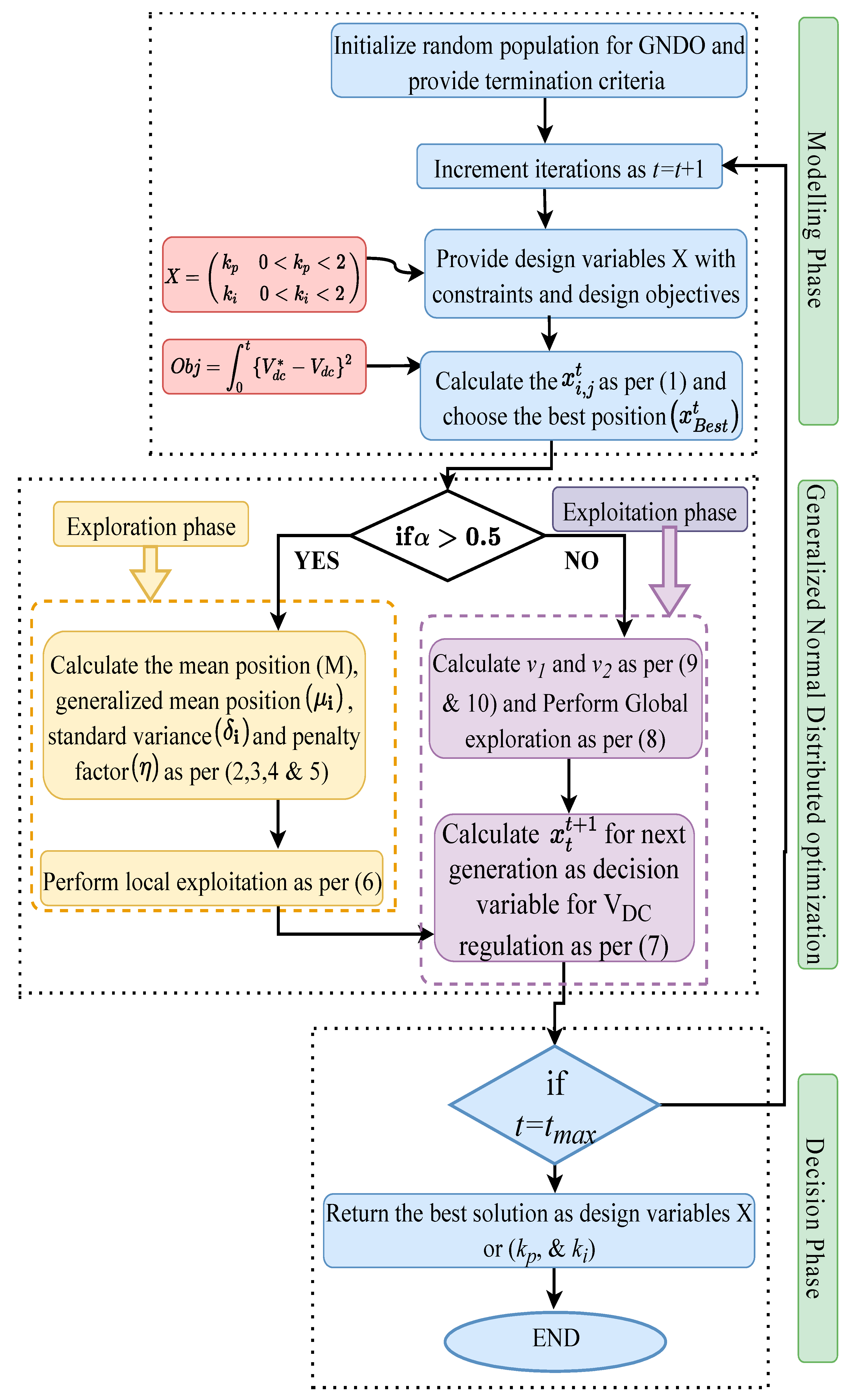
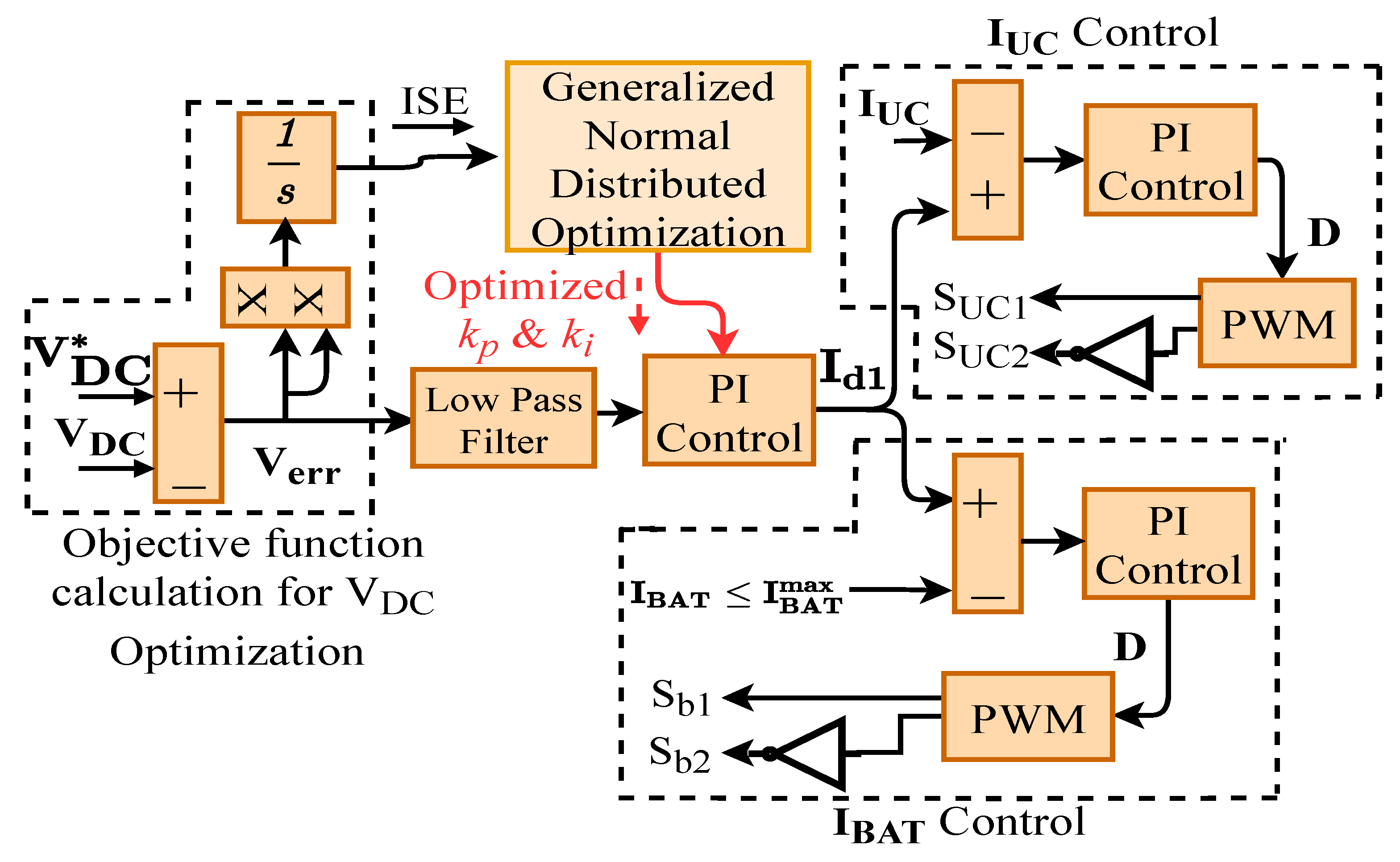
  • The GNDO algorithm is utilized for the optimal gain tuning of the PI controller to secure the V DC during various induced dynamic conditions in the system and generate the accurate loss component of current for enhanced VSC performance.
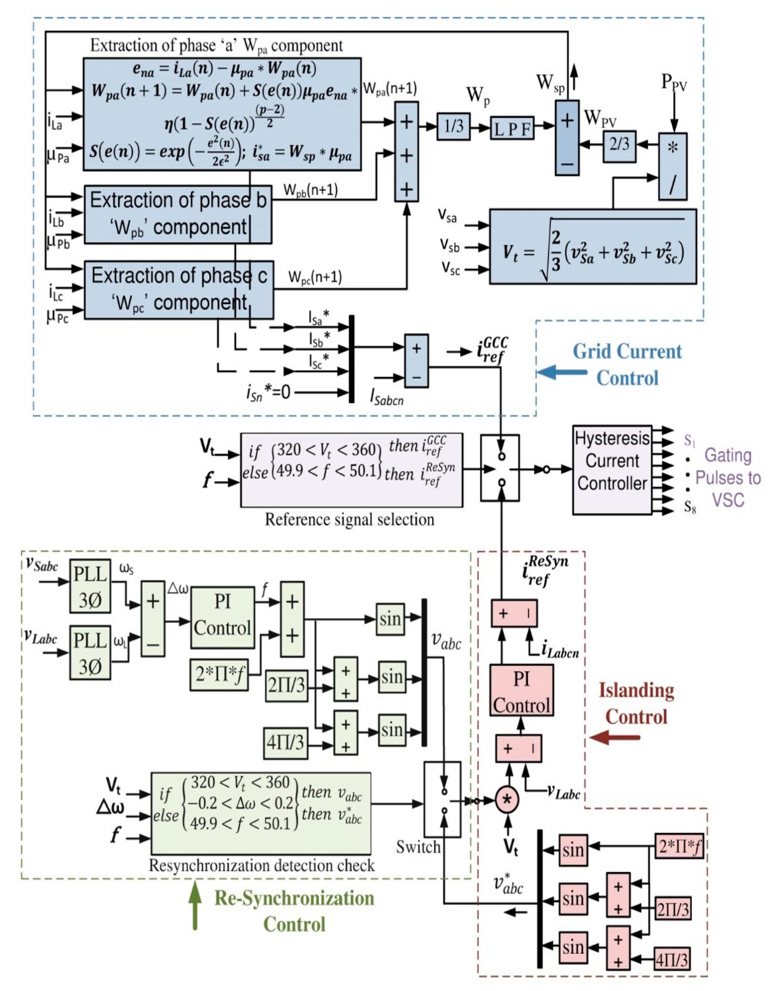
  • MRFKMP-based adaptive control of VSC is employed, that accurately extracts the fundamental load current component, delivers a better convergence rate with less computational complexity and performs better than other adaptive controls during both steady-state and dynamic state operations.
The rest of the paper is organized as follows: Section 2 describes the proposed topology and its description; Section 3 presents the implemented control strategies—VSC control, Seamless control, DC-DC bi-directional converter control and GNDO optimized DC link voltage control; Section 4 describes the results and discussions of the presented system during various induced dynamic conditions; Section 5 shows the main conclusions of the research work.

2. System Description

The topology of the presented system is shown in Figure 1. The PV array of 32 kW is simulated by keeping ‘Kyocera GT200’ module parameters as standard values. The incremental conductance (InC) algorithm is implemented to retain maximum power out of the PV system and provide a duty cycle for DC–DC boost converter control. The boost converter stabilizes the PV voltage ( V PV ) during irradiation variations and delivers the power to the DC bus. The battery and UC are also connected to the DC bus via bi-directional buck-boost converters to facilitate the two-way power communication between the energy HESS and the DC bus. Each buck-boost converter is provided with an individual current control mechanism for the battery and the UC. The three-phase four-wire VSC bridges the DC bus coupling capacitor to the rest of the AC system. The RC ripple filter and interfacing inductor are connected at the PCC to reduce the voltage and current ripples of the system and maintain the power quality of the grid. The non-linear load of 17 kW and the three-phase four-wire grid of 415 V (r.m.s.) at 50 Hz (via a master control switch) are also connected to the PCC. The master control switch allows the bidirectional flow of current to and from the grid.

3. System Controlling Strategies

The proposed system is governed by several controls: MRFKMP-based VSC control, seamless control for islanding and re-synchronization operation, bi-directional buck-boost converter control of HESS, DC bus voltage control by GNDO tuned PI and InC-based maximum power extraction.

3.1. Optimization-Based V D C Control

The V DC is controlled by a conventional PI controller. To improve the DC bus stability during dynamic conditions, the gains of the PI controller are tuned by GA, GA with pattern search and the GNDO algorithm. The DC bus voltage error ( V err ) is converted into the integral square error (ISE), and provided to the optimization algorithm as a cost function to be minimized with tuned gains of the PI controller.
The GNDO algorithm is inspired by the Gaussian distribution, being simple to implement as no special controlling parameters are required other than design variable D, upper and lower bounds ( u j and l j ), population size N and termination criteria. The GNDO function is implemented in two steps, local exploration and global exploitation, as shown in Figure 2.
The GNDO algorithm is initiated by selecting an appropriate N value and calculating the fitness function as the distance between the mean and the position of the ith individual x i t as per Equation (1). The best individual x b e s t   is selected based on the fitness function. In our problem, two design variables are considered as PI controller gains ( k p and k i ) to be tuned by GNDO to reduce variation in V DC ; N = 30, D = 2, λ 1 is the random number between 0 and 1; and u j = [10,10] and l j = [0,0] are chosen in the presented problem.
x i , j t = l j + ( u j l j ) λ 1   where   i = 1 , 2 , 3 , . . . . . , N ,   j = 1 , 2 , 3 , . . . , D
The total number of the iterations was selected as t = 50 and updated with every iteration. The local exploitation or global exploration step is selected depending on the randomly generated number ( 0 < α < 1 ). During local exploitation, mean position M, generalized mean position μ i , standard variance δ i and penalty factor η are calculated as per Equations (2)–(5). The relation between a normal distribution and an individual’s distribution is represented by the generalized normal distribution model as per Equation (6):
M = i = 1 N x i t N
μ i = 1 3 ( x i t + x B e s t t + M ) )
δ i = 1 3 [ ( x i t μ i ) 2 + ( x B e s t t μ i ) 2 + ( M μ i ) 2 ]
η = { l o g ( λ 1 ) c o s ( 2 π λ 2 ) ,   i f   a b l o g ( λ 1 ) c o s ( 2 π λ 2 + π ) ,   o t h e r w i s e }  
The a, b,   λ 1 and λ 2 are selected as a random variable between 0 and 1, and x B e s t t is the best position in the current iteration. The ith individual x i t is pushed towards the x B e s t t . The local exploitation is completed with a screening step that avoids the chances of getting trapped in local minima and pushes the best individual in the next-generation population as per Equations (6) and (7).
v i t = μ i + δ i η ,   where   i = 1 , 2 , 3 N
x i t + 1 = { v i t ,   i f   f ( v i t ) f ( x i t ) x i t ,   o t h e r w i s e }  
The global exploration is carried out based on local and global information sharing as per Equation (8), in which λ 3 and λ 4 are a random number concerning the standard normal distribution, and β is the adjusted parameter between 0 and 1. The v 1 and v 2 are calculated as per Equations (9) and (10), where p1, p2, and p3 are the random integers between 1 to N, but they cannot be p 1 p 2 p 3 i .
v i t = x i t + β ( | λ 3 | v 1 ) L o c a l   i n f o r m a t i o n + ( 1 β ) ( | λ 4 | v 2 ) g l o b a l   i n f o r m a t i o n
v 1 = { x i t x p 1 t ,   i f   f ( x i t ) f ( x p 1 t ) x p 1 t x i t ,   o t h e r w i s e }  
v 2 = { x p 2 t x p 3 t ,   i f   f ( x p 2 t ) f ( x p 3 t ) x p 3 t x p 2 t ,   o t h e r w i s e }  
The global exploration ends with the screening step as per Equation (7), and the optimization follows the same steps for all iterations until the termination criteria are reached.

3.2. VSC Control

The MRFKMP-based VSC with random Fourier feature approximated network structure reduces calculation burden and storage cost, and ensures freedom to choose kernel parameters for multiple kernels, as shown in Figure 3. The Gaussian kernel is an obvious choice for kernel adaptive filters (KAF) due to its universal approximation capability. The choice of kernel and its parameters is specific to the application, which can be selected by cross-validation, penalizing function, etc. Due to the large computational burden, it is difficult to apply KAF methods and achieve desirable online learning efficiency. The Multiple KAF (MKAF) solves the problem of kernel parameter selection, but it suffers from a linearly growing network and a large memory requirement. The random Fourier feature approximation delivers the fixed size network matrix in MRFKMP, which is unrestrained from the input signal. The excess mean square error (EMSE) as a loss function can handle Gaussian noise. For both Gaussian and non-Gaussian noises, the mean p-power criteria-based loss function is utilized in kernel space.
The error is e n x , where x = a,b,c, for each phase is generated as per Equation (11) as a function of the load current i L a and the in-phase component μ p a . μ p x , where x = a,b,c, is calculated as per Equation (12). The V d is voltage magnitude and v s x , where x = a,b,c, is the phase to ground source voltage [15].
e n x = i L x ( n ) μ p x W p x ( n ) ,   where   x = a , b , c
μ p x = v s x V d   ,   where   x = a , b , c
The S ( e ( n ) ) is calculated as a function of the error signal and further utilized in evaluating each phase weight signal W P x , where x = a,b,c, as per Equations (13)–(16).
S ( e ( n ) ) = e x p ( e n x 2 2 ϵ 2 )   where   x = a , b , c
W p a ( n + 1 ) = W p a ( n ) + η ( 1 S ( e ( n ) ) ) ( p 2 ) / 2 S ( e ( n ) ) μ p a e n a
W p b ( n + 1 ) = W p b ( n ) + η ( 1 S ( e ( n ) ) ) ( p 2 ) / 2 S ( e ( n ) ) μ p b e n b
W p c ( n + 1 ) = W p c ( n ) + η ( 1 S ( e ( n ) ) ) ( p 2 ) / 2 S ( e ( n ) ) μ p c e n c
The feed-forward term ( W PV ) is utilized to balance the grid current and reduces the voltage oscillations on the DC bus as per Equation (17). The overall weight ( W SP ) is calculated as a function of average weight W P and W PV as per Equations (18) and (19), and further utilized in generating the reference source currents i s x * , where x = a,b,c, as per Equation (20) [15].
W P V = 2 3 ( P P V 2 3 ( v s a 2 + v s b 2 + v s c 2 ) ) = 2 3 P P V V d
W p = 1 3 ( W p a + W p b + W p c )
W s p = W p W P V
i sx * = W sp μ p x   where   x = a , b , c
During specified power mode operation, the W SP is replaced by W s p f i x to supply a fixed amount of power to the grid, and i S x f i x * is generated with W s p f i x as per Equations (21) and (22).
W s p f i x = 2 3 ( P f i x 2 3 ( v s a 2 + v s b 2 + v s c 2 ) ) = 2 3 P f i x V d
i s x f i x * = W s p f i x μ p x   where   x = a , b , c
The i s x * , where x = a,b,c, or i S x f i x * are further provided to the hysteresis current controller (HCC) to generate the proper switching sequence for VSC.

3.3. Seamless Control
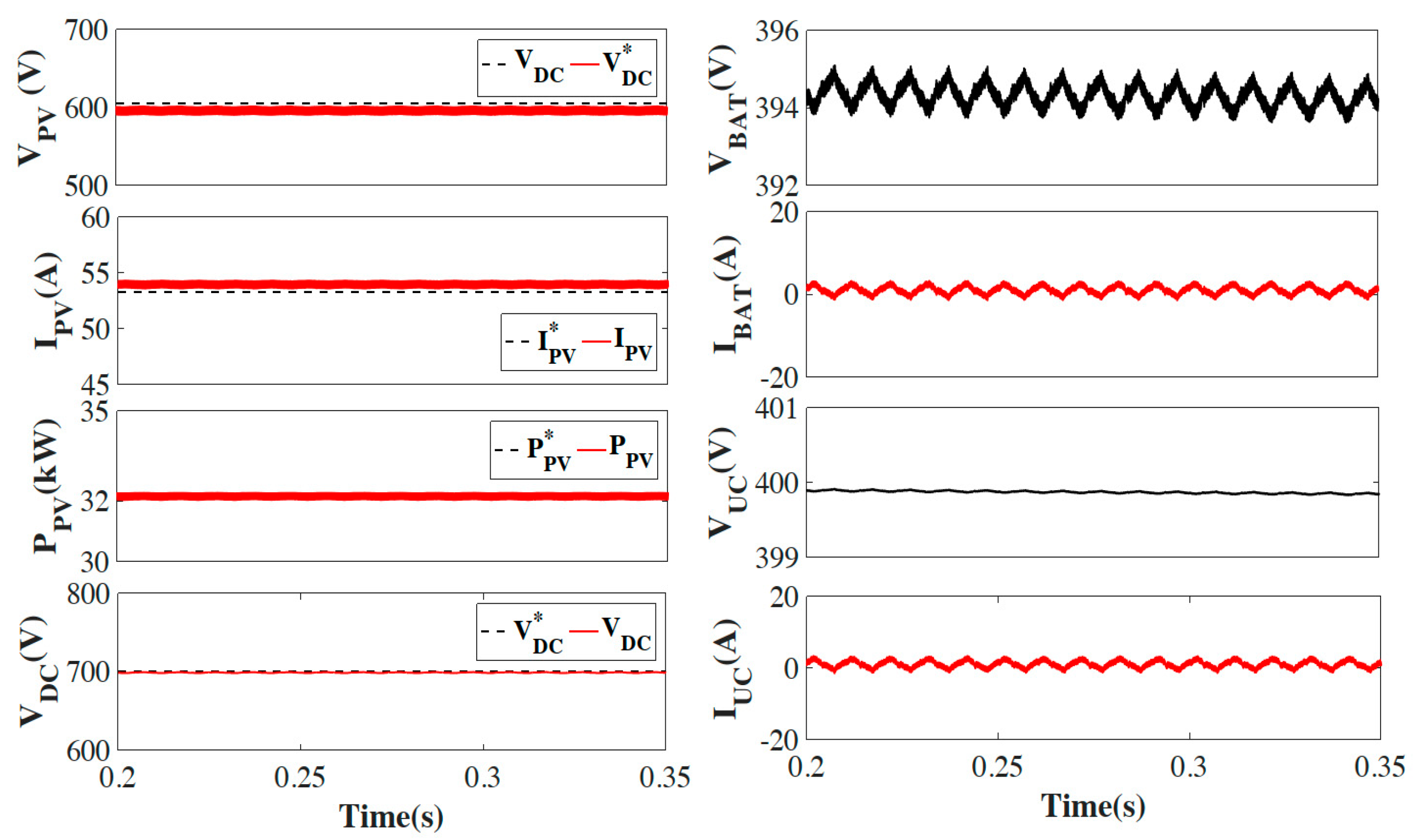
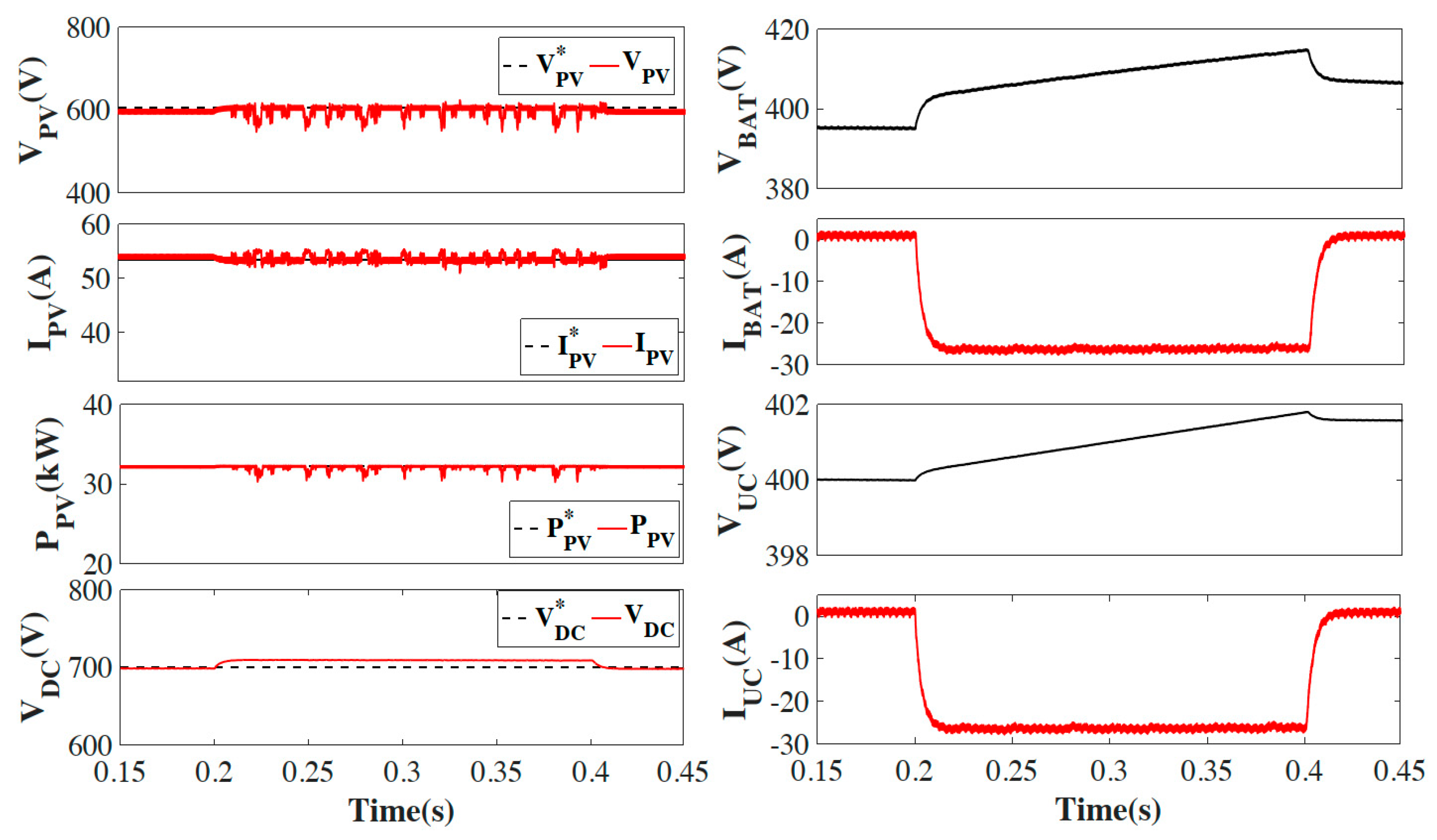
The seamless control facilitates the smooth transition of the VSC control from GCC during grid-tied operation to isolated voltage control during isolated operation, and back to GCC during grid re-synchronization operation of the system. With the initiation of the grid isolation, the grid V d and frequency (f) are reduced to zero, and the reference signal selector switch chooses the re-synchronization reference current ( i r e f R e S y n ) over the GCC reference currents ( i r e f G C C ) . During islanded operation, reference voltage ( v a b c * ) is multiplied with V d and compared with the load voltage ( v L a b c ) , provided to the PI controller and further compared with the load currents ( i L a b c n ) to generate ( i r e f R e S y n ) . The isolated operation of the system will be considered stable only when v L a b c maintains its frequency and amplitude. When the grid is about to be synchronized, the VSC control shifts from islanded control to the re-synchronization control of VSC. The re-synchronization period continues up to 5–10 cycles at 50 Hz, until grid synchronization is confirmed, in which the frequency matching of load and source voltages ( v L a b c ,   and   v S a b c ) is done. If the comparison of V d , f, and change in angular frequency ( ω ) of the incoming grid with the reference values remain within desirable limits, that ensures the stability of the grid. The weak grid re-synchronization may result in huge transients on grid voltage, current and frequency. Once the stability of the incoming grid is verified, the VSC control shifts from re-synchronization control to GCC, after checking the V d and f again, as shown in Figure 3.

3.4. HESS Control

The HESS, consisting of lead-acid battery and UC, is employed to tackle the system interruptions of sudden and sustained nature, occurring on the grid, load and the PV side. The DC bus voltage ( V DC ) control is provided with the conventional PI converter tuned with the GNDO algorithm. The loss component of current (Id1) is considered as reference current for battery ( I BAT ) and UC current ( I UC ) control. The battery requires overcurrent protection to maintain the life cycle of the lead-acid battery, whereas the UC does not require overcurrent protection. The duty cycles D1 and D2 are further utilized to generate the switching sequence for battery and UC connected buck-boost bi-directional converter control by pulse width modulation (PWM) technique at 10 kHz, as shown in Figure 4. The battery over current protection is provided by limiting the I BAT during the charging and discharging phase as I BAT I BAT max , where I BAT max = 30 A.

4. Results and Discussions

The system is scrutinized under steady-state, irradiation variation mode, specified power mode, unbalanced grid voltage, abnormal grid voltage, unbalanced load, islanding and re-synchronization mode, with optimized V DC .

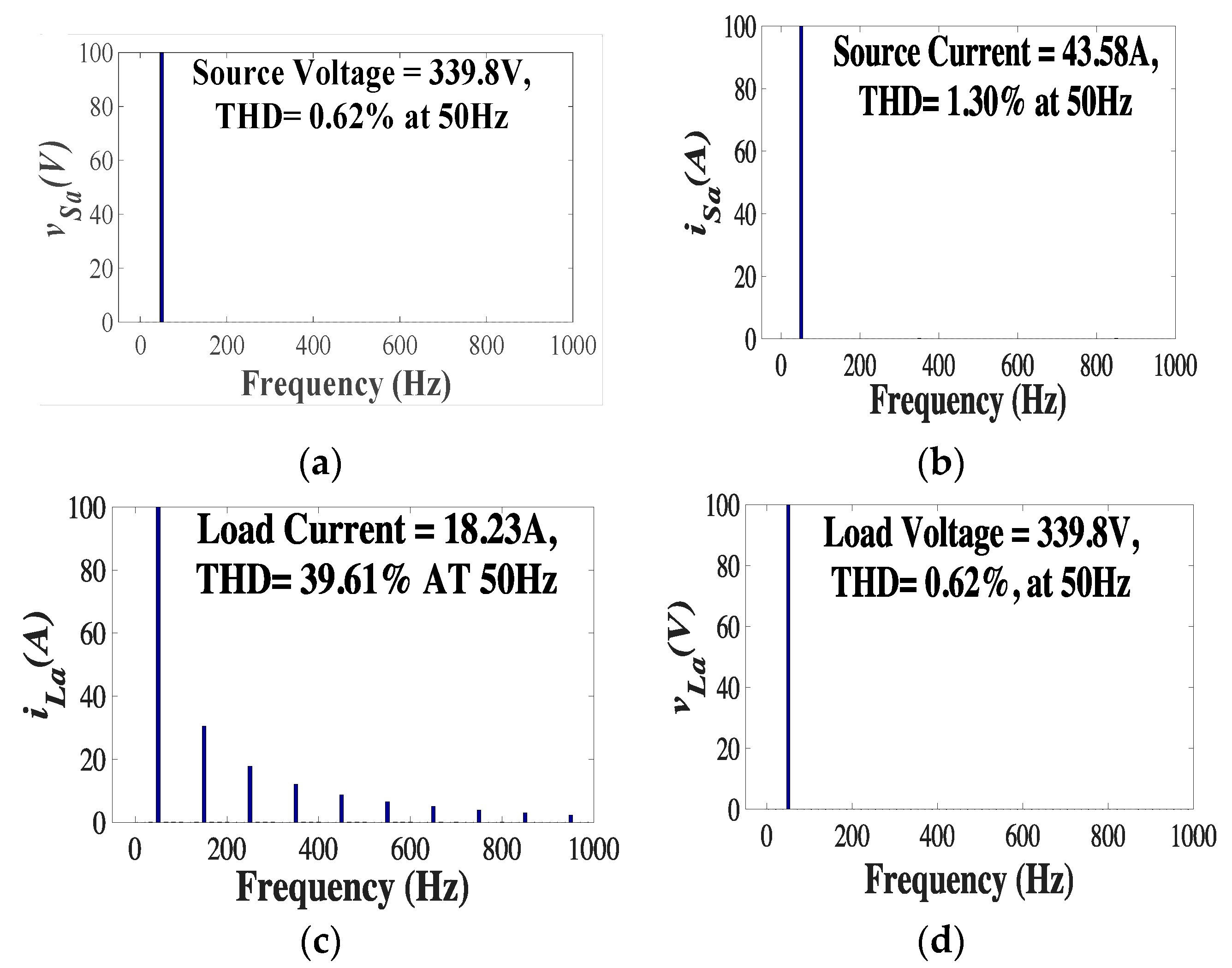
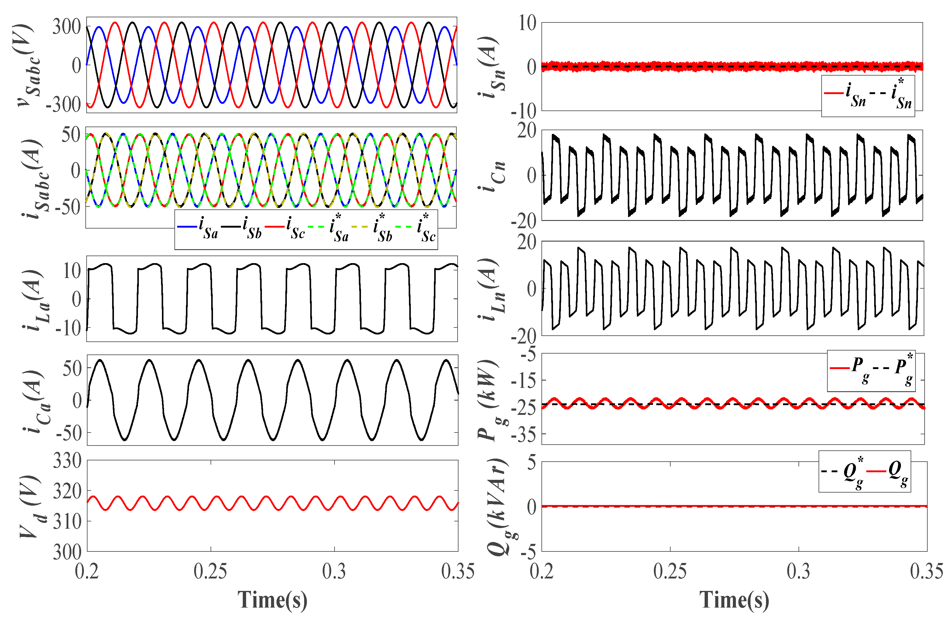
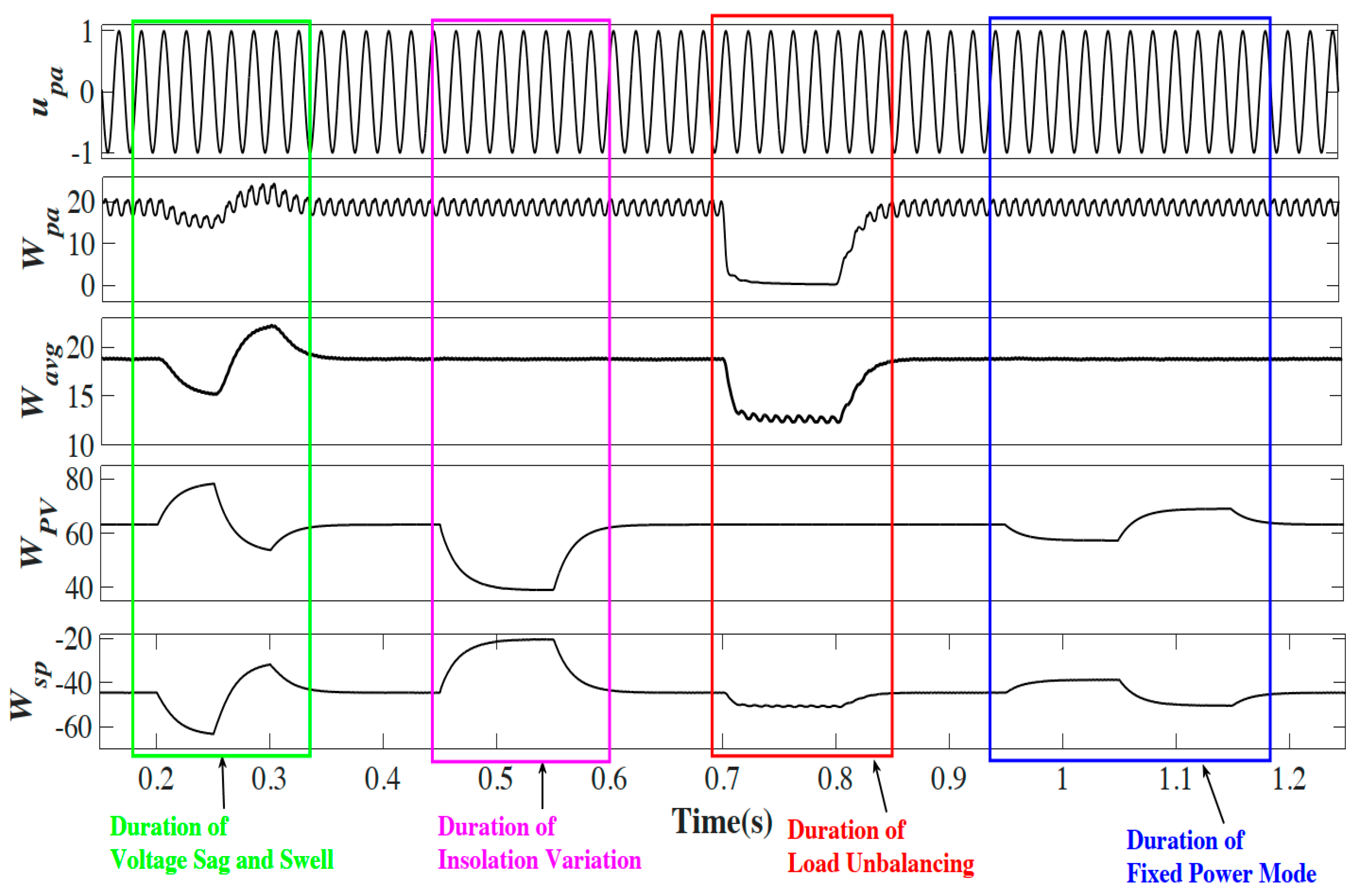
4.1. Steady-State Analysis

During steady-state operation, the irradiation level is kept at 1000 W/m2, at 250 standard temperatures. The total harmonics distortion (THD) is defined as the ratio of root mean square of the harmonics content, including the harmonics components, up to 50th order. The latest IEEE Standards 519–2014 provide the distortion limit of the v S a b c   and   i S a b c for designing an electrical system with both linear and non-linear loads, which must be maintained <5% for healthy operation. The THD of source voltage and current of phase ‘a’ ( v S a   and   i S a ) , and load voltage and current ( v L a   and   i L a ) are analysed and found satisfactory as per IEEE519 standards, as shown in Figure 5a–d.
The comparison of the THD of selected source, load, and compensator signals with various adaptive VSC controls, e.g., MCC, AKWMCC and proposed control, are also presented in Table 1.

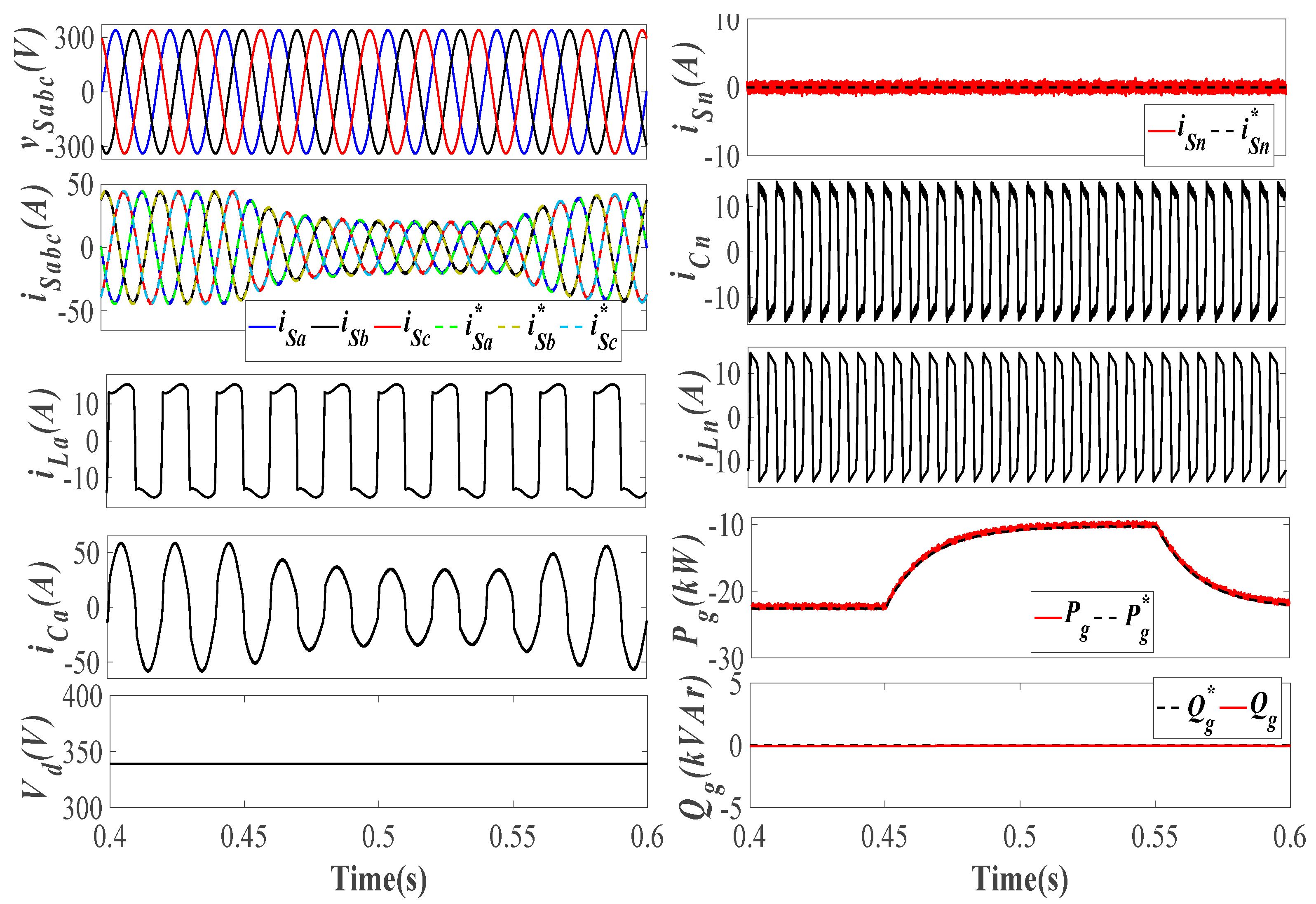
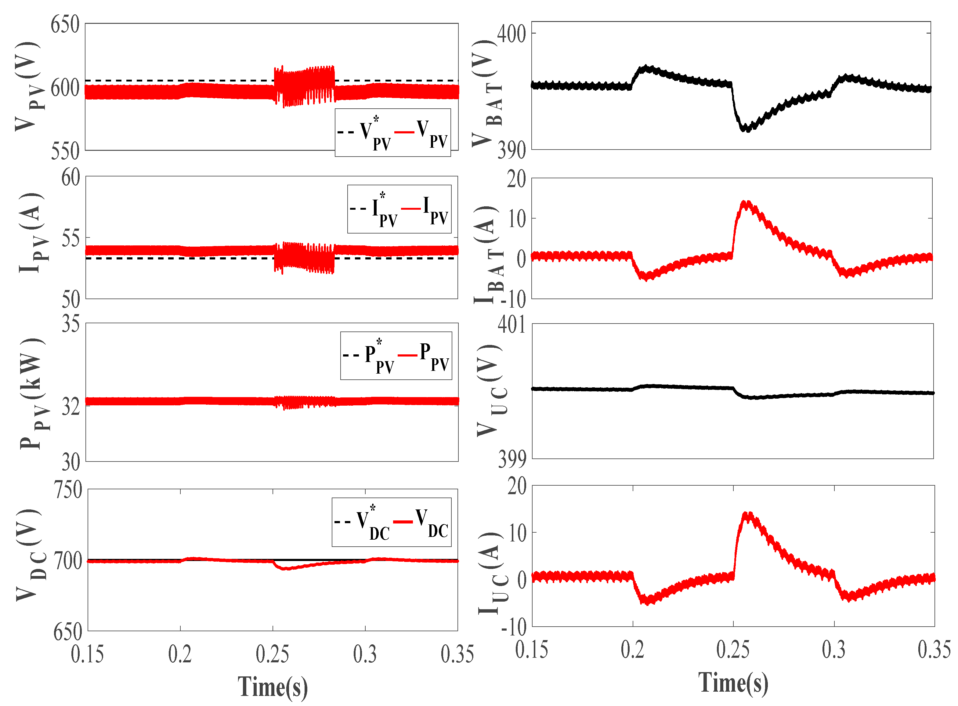
4.2. Irradiation Variation Analysis

The irradiation level is reduced from 1000 W/m2 to 600 W/m2 during 0.45 to 0.55 s of simulation time. As the active power ( P g ) is supplied to the grid, the source voltage ( v S a b c ) and current ( i S a b c ) keep the UPF in phase opposition to each other. The amplitude of i S a b c and P g reduces with the insolation level. The i S a b c is compared with reference current ( i S a b c * ) generated by the VSC control and found to be following its reference signals. The load and compensator currents ( i L a and i C a ) of phase ‘a’ are in phase with each other. The i S n ,   i L n , and   i C n are the source, load and compensator neutral currents, respectively. The i L n   and   i C n are exactly out of phase with each other, cancelling each other out and bringing i S n to zero, which is also its reference value ( i S n * = 0 ) . The VSC supplies the required reactive power ( Q g ) to the load, and Q g exchange with the grid is zero, which is its reference value ( Q g * = 0 ). The V d is maintained at 340 V during irradiation variation, as shown in Figure 6. On the DC side, the PV voltage, current and power ( V PV , I PV and P PV ) change with the insolation change in the same manner as their reference values ( V PV * , I PV *   and   P PV * ) . The battery and UC currents ( I BAT , I UC ) are slightly negative, with reduced insolation level, and battery start discharging, which is verified by the dip in battery and UC voltage ( V BAT , V UC ). The I BAT and I UC are the battery and UC currents, respectively. The V DC is maintained at the desired level of 700 V during irradiation variation, as shown in Figure 7.

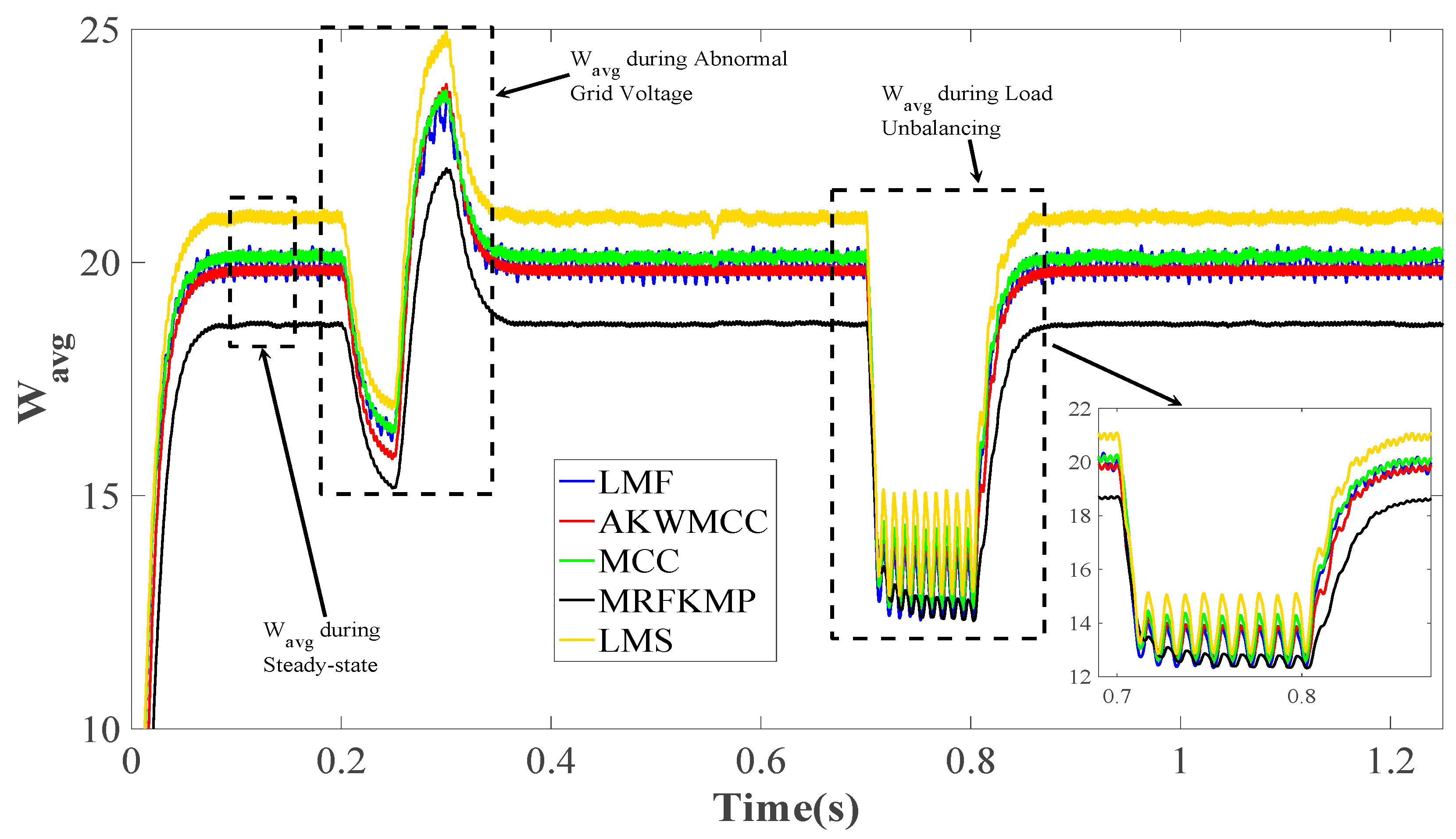
4.3. Unbalanced Grid Voltage Analysis

The grid voltage unbalancing is created by decreasing the phase ‘a’ amplitude to 0.8p.u., keeping it as it is for the remaining two phases. The v S a b c and i S a b c maintain UPF in phase opposition. The i S a b c and i S a b c * are the same without any distortion due to grid voltage unbalancing. The i L a and i C a remain in phase with each other, and V d reduces with the voltage unbalancing. The i L n and i C n are revolving at thrice the fundamental frequency in phase opposition. The P g delivered to the grid shows variations due to the grid voltage unbalancing but tries to settle down on P g * . The i S n and Q g are kept around zero as i S n * and Q g * , as shown in Figure 8.
On the DC side, V PV , I PV and P PV show no change and keep following their references as irradiation level is kept fixed at 1000 W/m2. The I BAT and I UC variations change the HESS from charging to discharging mode as grid voltage is unbalanced. The DC bus stability is preserved, and V DC is maintained at 700 V while following the V DC * , as shown in Figure 9.

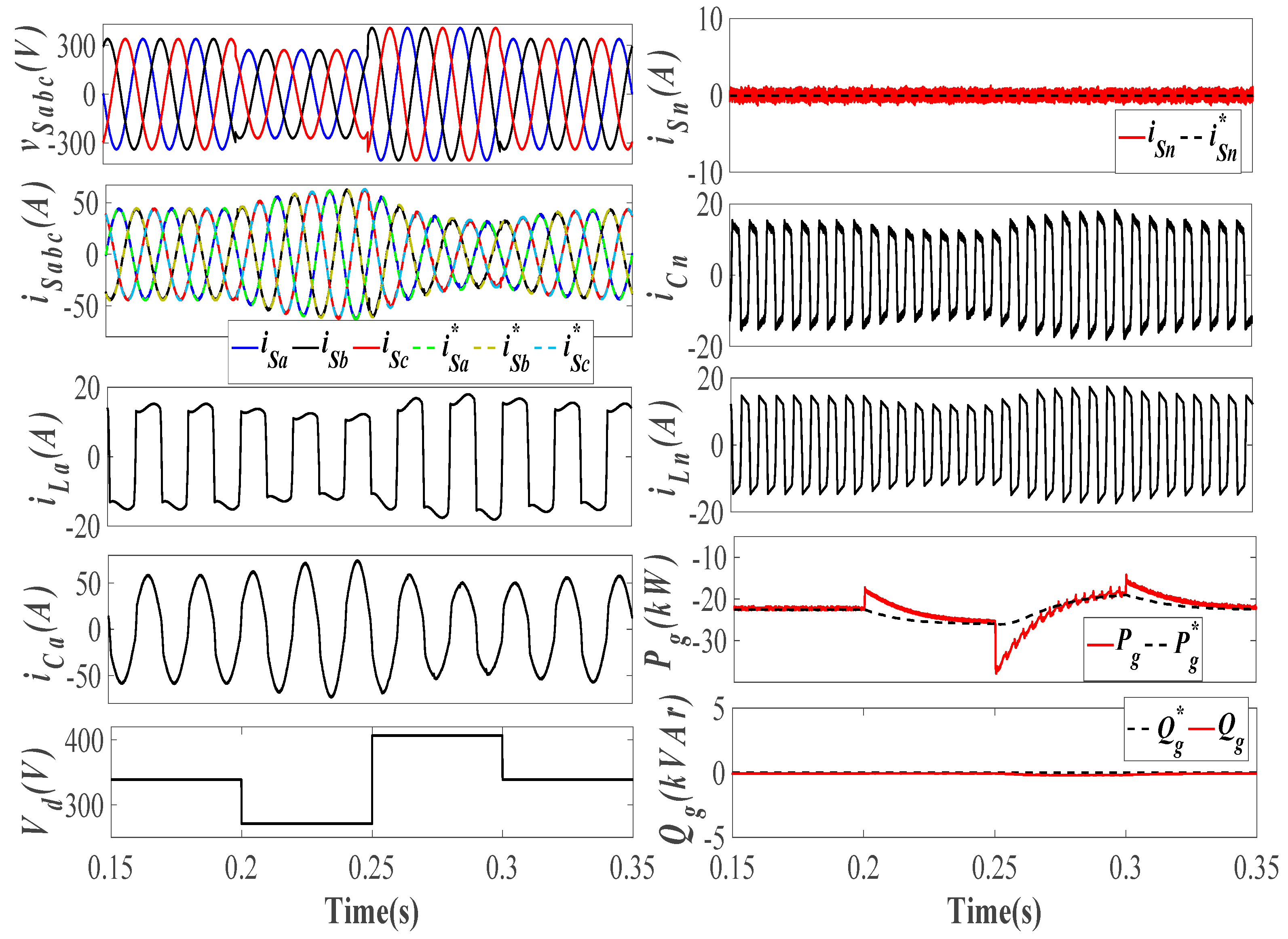
4.4. Abnormal Grid Voltage Analysis

The grid voltage sag and swell are created by varying the three-phase voltage magnitude to 0.8 p.u. during voltage sag from 0.2 s to 0.25 s, and 1.2 p.u. during voltage swell from 0.25 s to 0.3 s of simulation time. The variation in i S a b c and its reference i S a b c * with the abnormal grid voltage are shown in Figure 10. With voltage sag for the same amount of P g delivered to the grid, i S a b c will increase and subsequently decrease for the voltage swell. The variation in V d clearly shows the voltage sag and swell. The i L n and i C n maintain the in-phase relation, and i L n and i C n remain in phase opposition with each other. The i S n and Q g is maintained around zero with negligible reactive power exchange with the grid. The P g shows variations with grid voltage abnormality but settles down to reference value. On the DC side, HESS changes its mode from charging during voltage sag to discharging during voltage swell to maintain the balance of power. The V DC is kept at the desired value of 700 V, as shown in Figure 11.

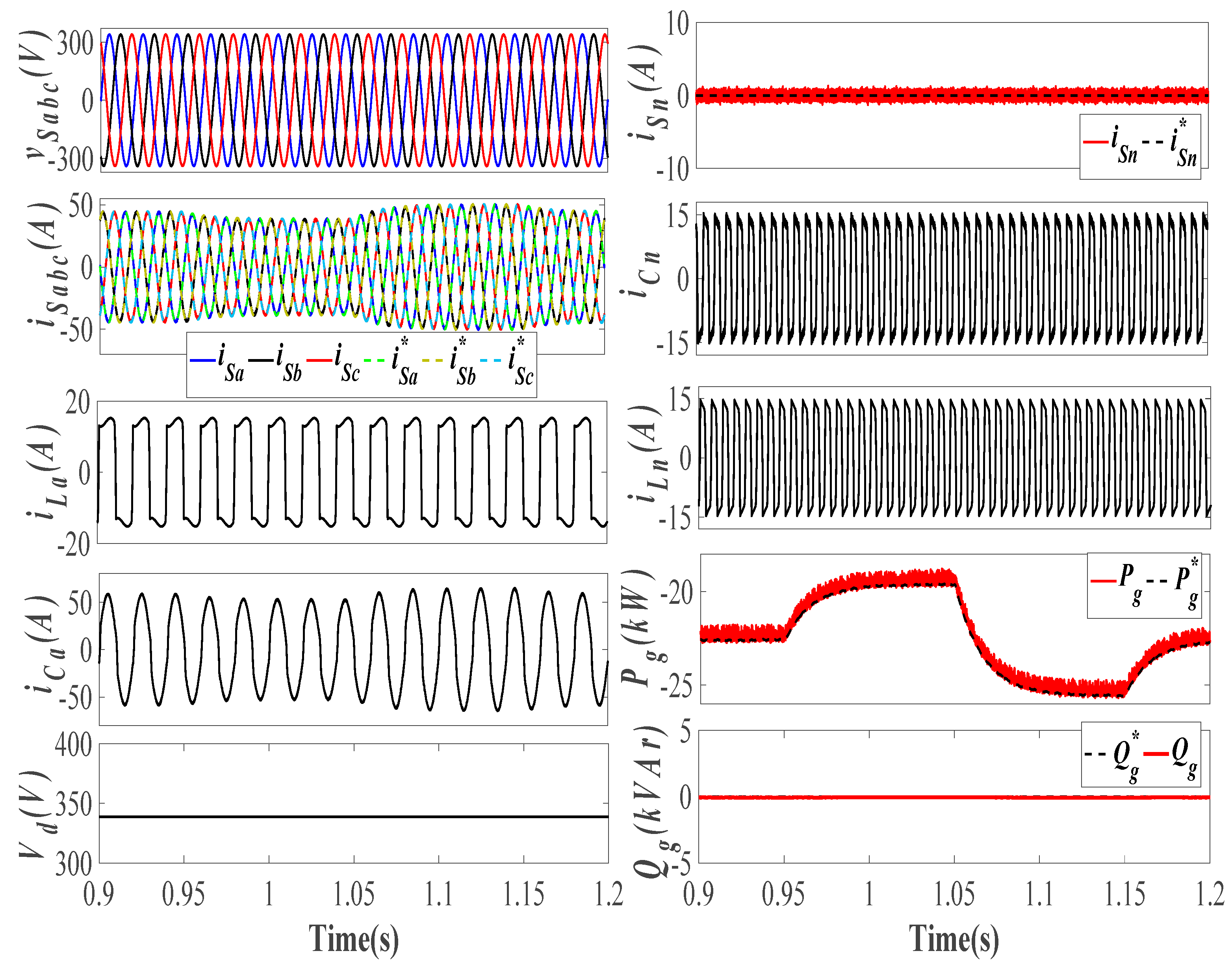
4.5. Specified Power Mode Analysis

During the specified power mode, the system pre-decides the amount of power that is extracted from the system. The fixed power mode is simulated from 0.95 to 1.15 s of simulation time. The P g delivered to the grid decreases to 17 kW from 0.95 s to 1.05 s, and further increases to 25.5 kW from 1.05 s to 1.15 s of simulation time, which shows the ability of VSC to provide the pre-decided amount of power for peak shaving. With the varying P g , the i S a b c also varies at the constant v S a b c . The v S a b c and i S a b c maintain the UPF, i L a and i C a remain in phase with each other, i L n and i C n remain in phase opposition at thrice the fundamental frequency that results in i S n   matching its reference, i.e., zero, and Q g is also maintained at zero, as shown in Figure 12. On the DC side, V PV , I PV , and P PV remain the same as in steady-state. The HESS changes from charging to discharging mode as P g delivered to grid decreases and then increases, which can be verified from V BAT , I BAT and V UC , I UC . The V DC is maintained at 700 V and keeps following V DC * , as shown in Figure 13.

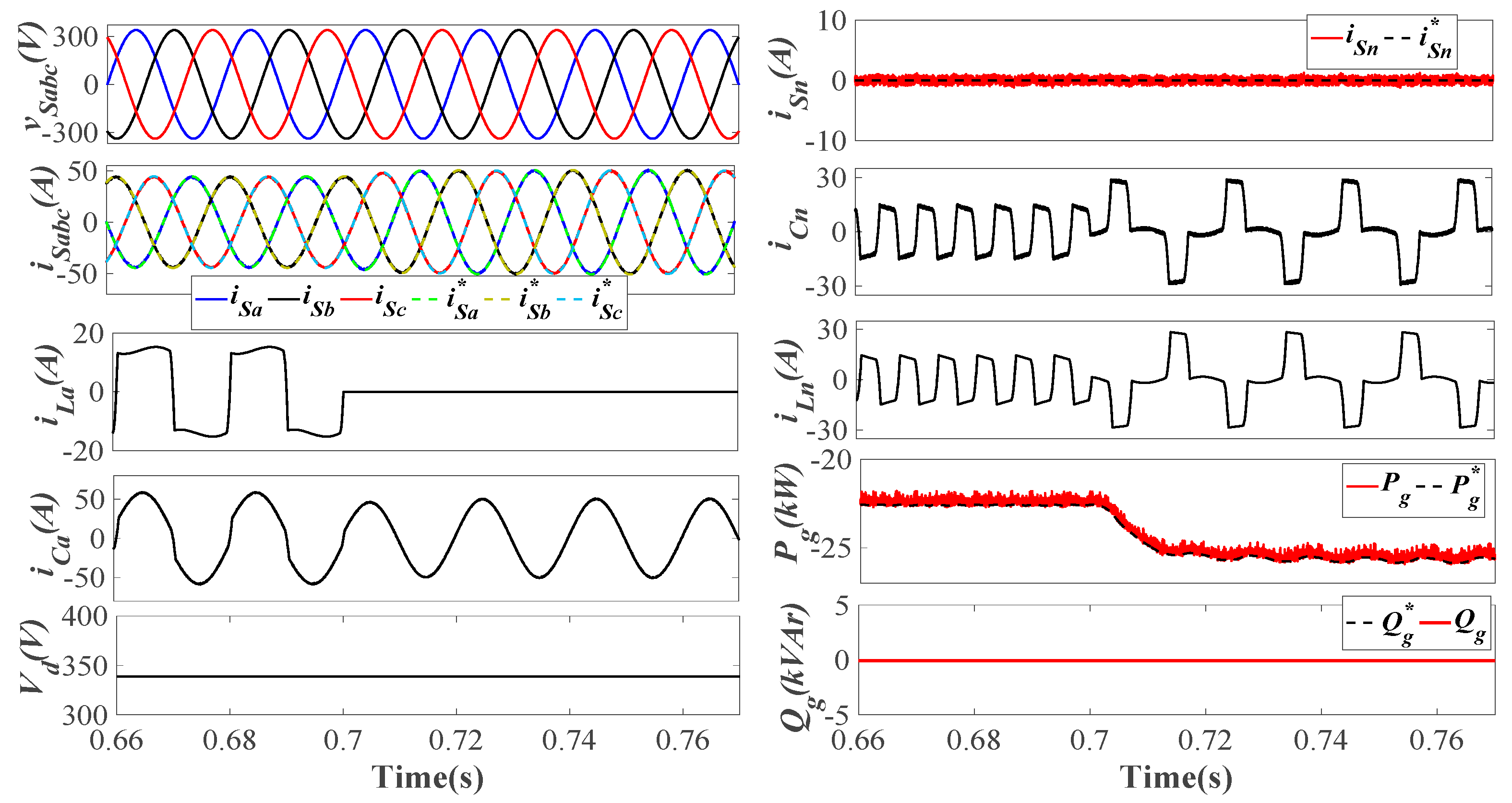
4.6. Unbalanced Load Analysis

The load unbalancing is simulated by disconnecting the phase ’a’ of the load from the rest of the system from 0.7 s to 0.8 s of simulation time. With phase ‘a’ of load disconnected, the power requirement of load also reduces, which can be verified by the reduced magnitude of i S a b c and increased magnitude of P g . The i L n and i C n start revolving with twice the fundamental frequency and maintain the i S n around i S n * . The Q g also kept around zero. The i S a b c ,   i S n , P g , and Q g follow their reference signals and maintain the stability of the system, as shown in Figure 14. On the DC side, VPV, IPV and PPV show no variations and keep following their respective reference signals. The I BAT and I UC become slightly negative and start charging with a reduced load. The V DC remains stable at 700 V, ensuring the stability of the system, as shown in Figure 15.

4.7. Internal Signal Analysis

The μ p a ,   W pa , W avg ,   W PV ,   and   W sp are considered as the internal signals of the proposed system. Their behavior during various dynamic conditions have been analyzed under abnormal grid voltage conditions, insolation variation, load unbalancing and specified power mode, as shown in Figure 16. The W avg ,   W PV ,   and   W sp show maximum variations in their weights during abnormal grid voltage conditions. During insolation variation, only W PV and W SP were changing to maintain the power balance between the system and the grid. During the load unbalancing, the W pa reduces to zero and its effect can be seen on W avg . During fixed power mode, the power balancing at PCC is also achieved with W PV and W SP . The μ p a remains sinusoidal with unity amplitude throughout the dynamic states. The comparison of the W avg with different adaptive controls, i.e., LMS, LMF, MCC, AKWMCC and MRFKMP, is shown in Figure 17. The W avg shows variations during abnormal grid voltage and load unbalancing operation.
The LMS delivers high steady-state error as compared to LMF. The MCC and AKWMCC present almost similar weights; AKWMCC shows fewer variations as compared to MCC during steady-state and dynamic conditions. The MRFKMP-based VSC control delivers the more accurate weight signals with reduced variations during abnormal grid voltage and load unbalancing, and it results in reduced overall losses in the system and provides better efficiency. The comparative analysis of the proposed control with LMS, LMF, MCC, AKWMCC and MRFKMP is shown in Table 2.

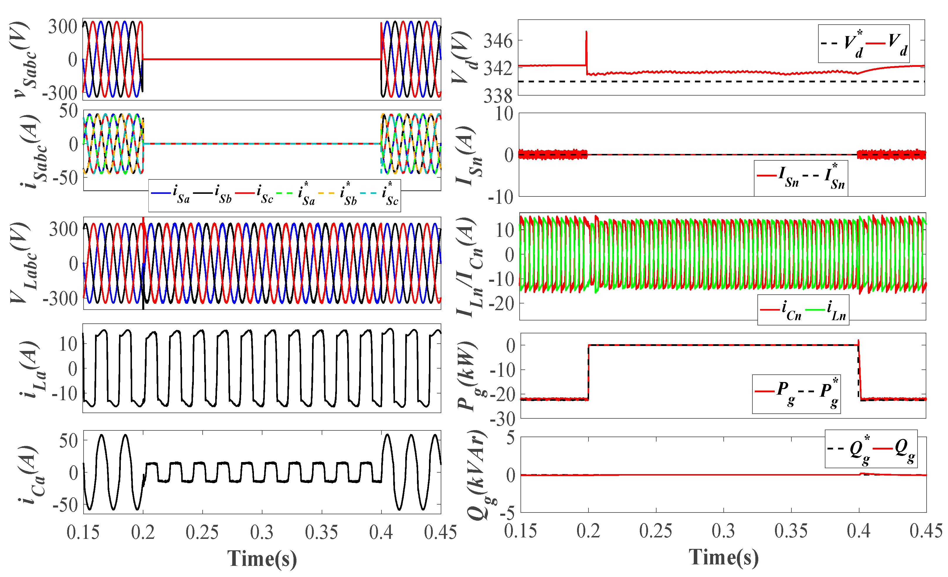
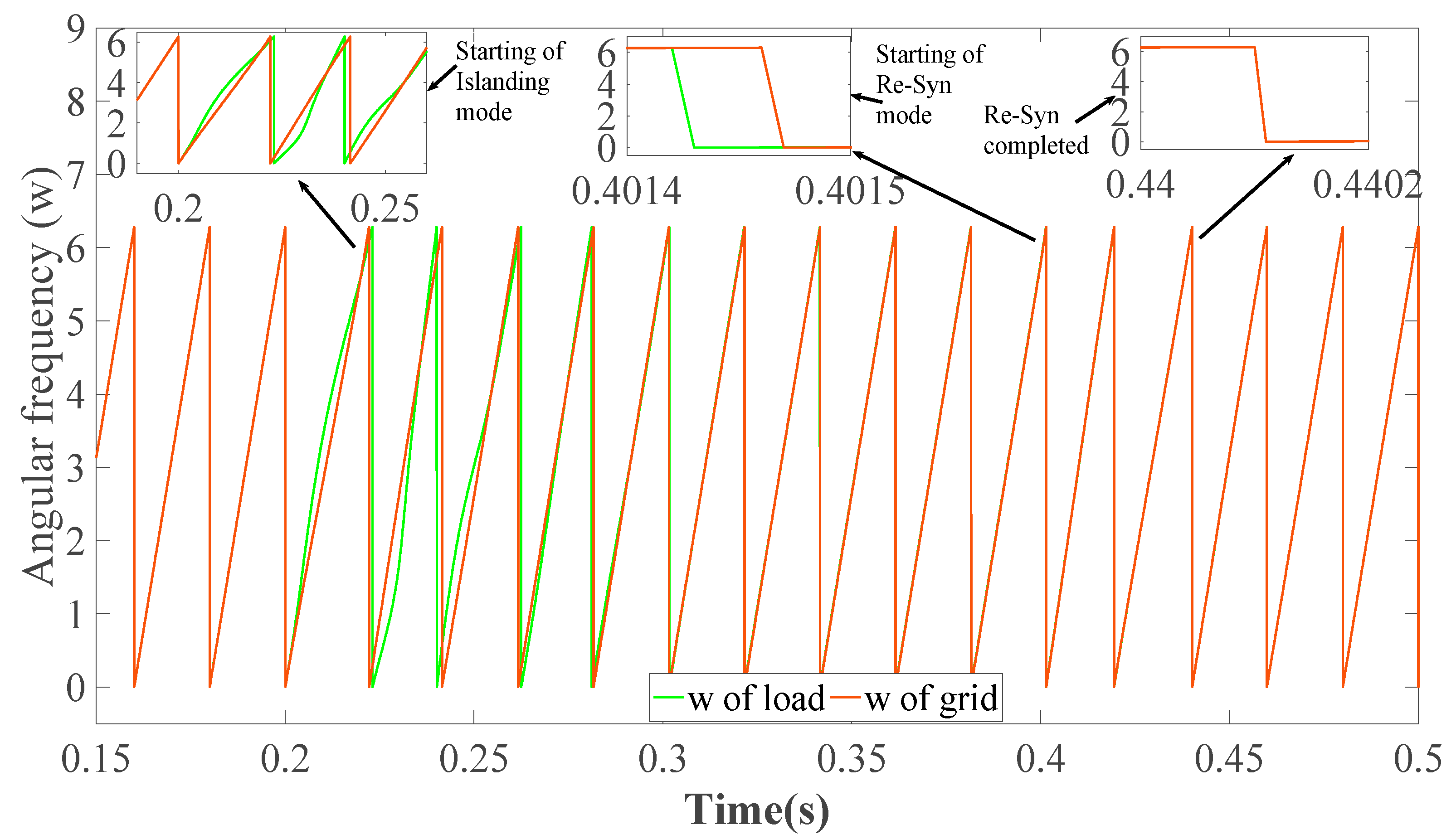
4.8. Islanding and Re-Synchronization Analysis

The islanding is induced by the master control switch from 0.2 s to 0.4 s, and the grid re-synchronization is initiated at 0.4 s of simulation time. During islanding v S a b c ,   and   i S a b c reduce to zero; v L a b c is maintained at the desired amplitude and frequency during islanding operation. With islanding i C a , amplitude reduces as P g is supplied to the grid, and VSC must satisfy load only. The V d during the islanded operation is maintained around the V d * = 340. The i L n and i C n cancel each other out, which results in i S n = 0. The P g and Q g exactly follow their reference values P g * and Q g * , as shown in Figure 18. The re-synchronization is initiated at 0.4 s, and the system is kept under intentional islanding for a few cycles to ensure the grid stability, in which the f, ω and V d of load are matched with the incoming grid. The re-synchronization is completed within four cycles without any major transients in the grid. On the DC side, IPV, VPV, and PPV remain on the desired levels as their reference signals with minor variations in isolated mode. The I BAT and I UC become negative and start charging as is P g delivered to the grid until they are zero, and an excess amount of power is utilized by HESS charging. The increase in the rate of charging of HESS can be verified from increasing amplitude of V BAT and V UC . With the reconnected grid, the HESS charging rate is reduced, and the system continues with the P g supply to the grid. The V DC is maintained at the desired level of 700 V during the whole operation, as shown in Figure 19. With the islanding of the grid, the angular frequency ( ω ) of v L a b c deviates from v S a b c . As the grid re-synchronization is initiated at 0.4 s, it becomes essential to match the ω of load with the incoming grid, which is done by resynchronization control. The system took 2–3 cycles at 50 Hz to re-synchronize the incoming grid with the system, as shown in Figure 20.

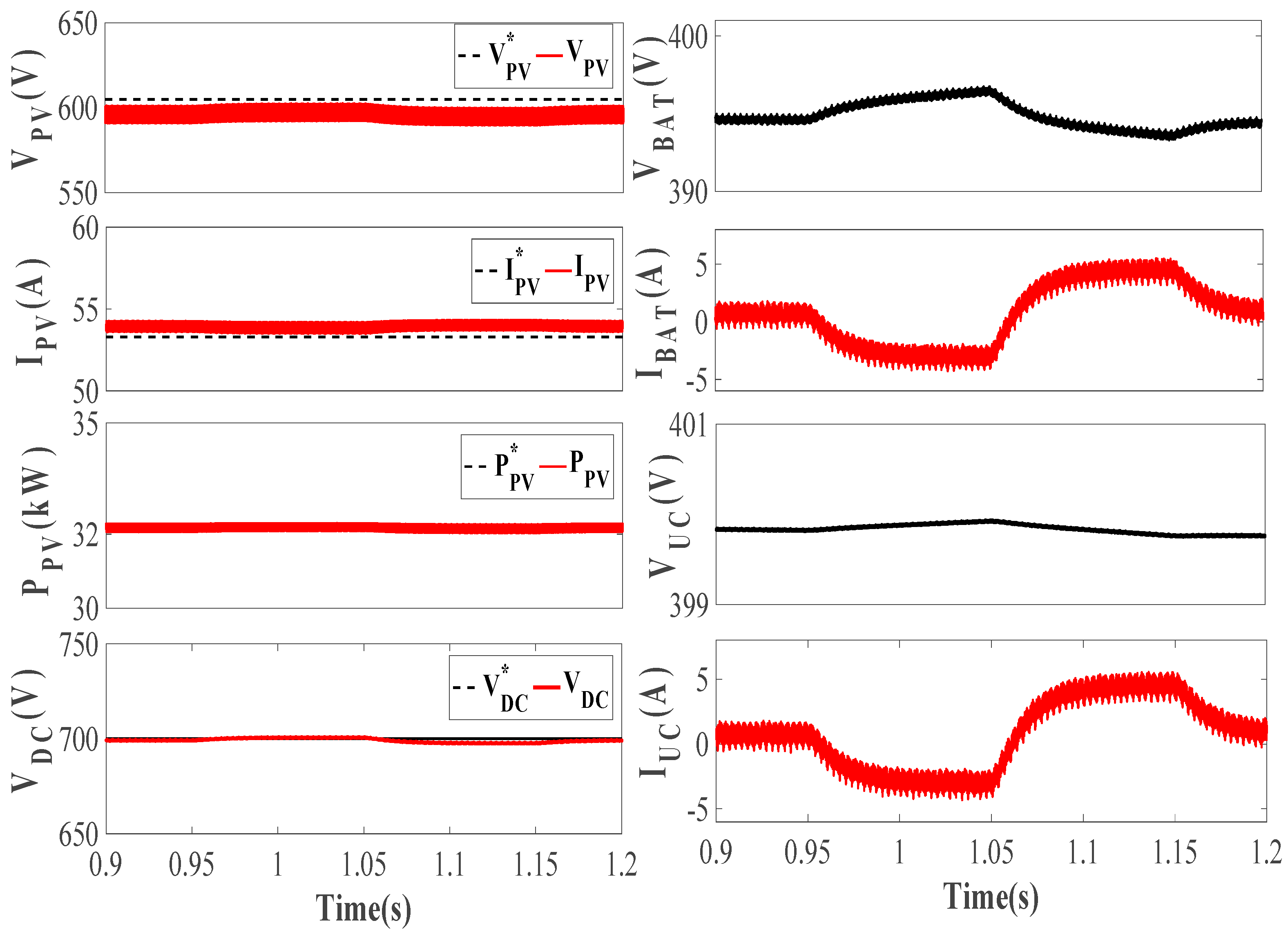
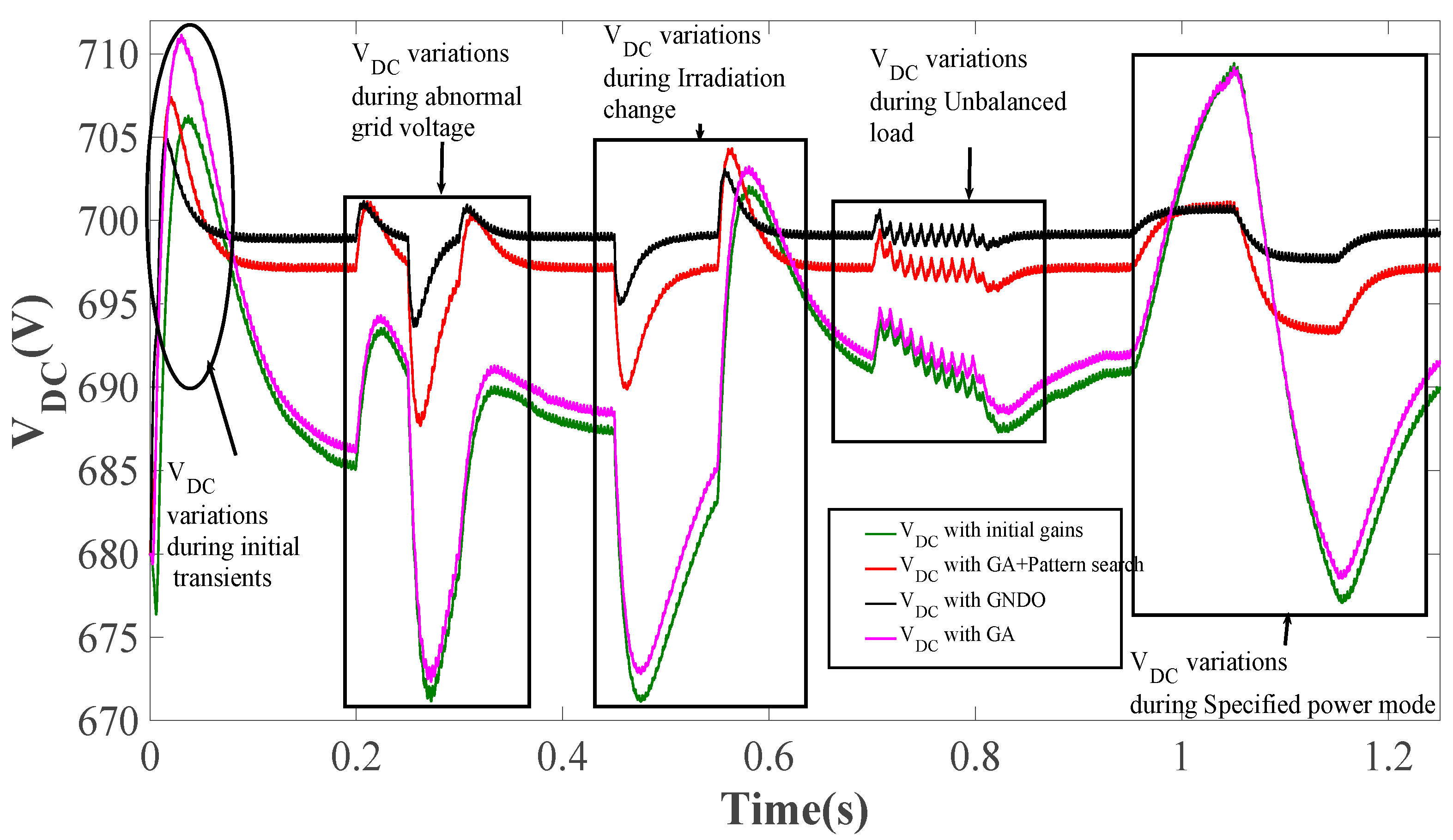
4.9. Optimized DC Bus Analysis

The V DC variations with the induced dynamic conditions should be minimum to maintain the stability of the system, and it reduces the need for a larger coupling capacitor. The DC bus controlled by PI controller gains is tuned with GA, GA with pattern search and GNDO algorithm. The V DC regulated by the GNDO algorithm generates the accurate Id1, which eventually enhances the operational capability of VSC control, as shown in Figure 21. The Id1 variations during diverse dynamic conditions are minimum with GNDO-regulated V DC . The Id1 generated by initial gain tuned and GA tuned V DC show large variations. Id1 performance of GA with pattern search tuned V DC is comparable with GNDO tuned V DC , but as GNDO tuned V DC provides Id1 closer to zero with reduced variations. The accurate Id1 helps the MRFKMP-based VSC to achieve faster convergence, precise generation of the fundamental component of load current and reduced steady-state losses. The comparison of V DC during initial transients, abnormal grid voltage, insolation variation, unbalanced load and specified power mode is shown in Figure 22. The gains of the tuned PI controller with various optimization techniques are presented in Table 3.

5. Conclusions

This paper presents a GNDO MRFKMP-based VSC control of a three-phase four-wire grid-tied dual-stage PV system. The DC bus has been regulated by the gain optimized conventional PI controller that generates a precise loss component of current, improves power quality, and enhances the VSC performance. The optimization is done on an off-line basis, so it did not increase the complexity of the VSC control. The MRFKMP-based VSC control extracts an accurate fundamental loss current component with a reduced computational burden due to random Fourier feature approximation. The MRFKMP delivers the reduced steady-state error but its convergence speed has been comparable with LMS and LMF algorithms though they are simple algorithms. The VSC conducts multi-functional operations, i.e., power quality improvement, reactive power compensation, load balancing, power balancing at the point of common coupling, etc., during diverse dynamic operating conditions. The GNDO-based MRFKMP allows a seamless transition of VSC control from grid current control mode to isolated voltage control mode during grid islanding and re-synchronization. The seamless transfer of VSC control is achieved without any large transients on the load and grid side while maintaining the desired frequency and load voltage during islanded operation. The grid re-synchronization has been achieved in four cycles at 50 Hz. The hybrid energy storage system enhances the sustainability and reliability of the PV system by satisfying load during the nighttime and in poor weather. The proposed system operates satisfactorily under various dynamic conditions, e.g., sudden irradiation change, unbalanced load, abnormal and unbalanced grid voltage mode. The total harmonic distortion of the grid voltage and current remains below 5% as per IEEE519 standards throughout the operation. A trade-off has to be made between steady-state error and convergence speed while utilizing the proposed VSC control. The complex VSC control reduces the steady-state error at the cost of convergence speed, which is also a drawback of the proposed control.

Author Contributions

The presented work was developed by the following contributions: conceptualization, methodology: M.C.; software, formal analysis, research, writing—original draft preparation: I.H. and A.A.; Writing—review and editing, and supervising: H.M.; Writing—review and editing, and supervising: F.P.G.M. All authors have read and agreed to the published version of the manuscript.

Funding

This research was funded by Universidad de Castilla-La Mancha under Research Grant ProSeaWind project (Ref.: SBPLY/19/180501/000102) and the APC was funded by Dirección General de Universidades, Investigación e Innovación of Castilla-La Mancha.

Acknowledgments

The work reported herewith has been financially supported by the Dirección General de Universidades, Investigación e Innovación of Castilla-La Mancha, under Research Grant ProSeaWind project (Ref.: SBPLY/19/180501/000102).

Conflicts of Interest

The authors declare no conflict of interest. The funders had no role in the design of the study; in the collection, analyses, or interpretation of data; in the writing of the manuscript, or in the decision to publish the results.

References

  1. IEA, Solar PV, IEA, Paris. 2020. Available online: https://www.iea.org/reports/solar-pv (accessed on 13 October 2020).
  2. Thotakura, S.; Chandan, S.; Xavier, J.F.; Quanjin, M.; Ramakrishna, G.; Gangwar, P.; Lakshmi, S. Operational performance of megawatt-scale grid integrated rooftop solar PV system in tropical wet and dry climates of India. Case Stud. Therm. Eng. 2020, 18, 100602. [Google Scholar] [CrossRef]
  3. IEA. World Energy Outlook 2020, IEA, Paris. 2020. Available online: https://www.iea.org/reports/world-energy-outlook-2020 (accessed on 13 October 2020).
  4. Rohankar, N.; Jain, A.K.; Nangia, O.P.; Dwivedi, P. A study of existing solar power policy framework in India for viability of the solar projects perspective. Renew. Sustain. Energy Rev. 2016, 56, 510–518. [Google Scholar] [CrossRef]
  5. National Power Portal India. Total installed power capicity. 2021. Available online: https://npp.gov.in/dashBoard/cp-map-dashboard (accessed on 1 June 2021).
  6. Arcos-Vargas, A.; Nuñez, F.; Román-Collado, R. Short-term effects of PV integration on global welfare and CO2 emissions. An application to the Iberian electricity market. Energy 2020, 200. [Google Scholar] [CrossRef]
  7. Singh, B.; Chandra, A.; Al-haddad, K. Power Quality Problems and Mitigation Techniques; John Wiley and Sons: Hoboken, NJ, USA, 2014. [Google Scholar]
  8. Krithiga, S.; Gounden, N.A. Investigations of an improved PV system topology using multilevel boost converter and line commutated inverter with solutions to grid issues. Simul. Model. Pract. Theory 2014, 42, 147–159. [Google Scholar] [CrossRef]
  9. Davila-Gomez, L.; Colmenar-Santos, A.; Tawfik, M.; Castro-Gil, M. An accurate model for simulating energetic behavior of PV grid connected inverters. Simul. Model. Pract. Theory 2014, 49, 57–72. [Google Scholar] [CrossRef] [Green Version]
  10. Chawda, G.S.; Shaik, A.G.; Mahela, O.P.; Padmanaban, S.; Holm-Nielsen, J.B. Comprehensive review of distributed FACTS control algorithms for power quality enhancement in utility grid with renewable energy penetration. IEEE Access 2020, 8, 107614–107634. [Google Scholar] [CrossRef]
  11. Shah, P.; Singh, B. Kalman filtering technique for rooftop-PV system. IEEE Trans. Sustain. Energy 2020, 11, 282–293. [Google Scholar] [CrossRef]
  12. Sharma, V.; Gidwani, L. Recognition of disturbances in hybrid power system interfaced with battery energy storage system using combined features of Stockwell transform and Hilbert transform. Energy 2019, 7, 671–687. [Google Scholar] [CrossRef]
  13. Agarwal, R.K.; Hussain, I.; Singh, B. Application of LMS-based NN structure for power quality enhancement in a distribution network under abnormal conditions. IEEE Trans. Neural Netw. Learn. Syst. 2018, 29, 1598–1607. [Google Scholar] [CrossRef]
  14. Agarwal, R.K.; Hussain, I.; Singh, B. LMF-based control algorithm for single stage three-phase grid integrated solar PV system. IEEE Trans. Sustain. Energy 2016, 7, 1379–1387. [Google Scholar] [CrossRef]
  15. Xiong, K.; Shi, W.; Wang, S. Robust multikernel maximum correntropy filters. IEEE Trans. Circuits Syst. II Express Briefs 2020, 67, 1159–1163. [Google Scholar] [CrossRef]
  16. Agarwal, R.K.; Hussain, I.; Singh, B. Integration of single-stage SPV generation to grid using admittance based LMS technique. In Proceedings of the 2016 International Conference on Emerging Trends in Electrical Electronics and Sustainable Energy Systems (ICETEESES), Sultanpur, India, 11–12 March 2016; pp. 308–313. [Google Scholar] [CrossRef]
  17. Kumar, A.; Singh, B.; Jain, R. Double stage grid-tied solar PV system using HC-LMS control. In Proceedings of the IEEE 9th Power India International Conference (PIICON 2020), Sonepat, India, 28 February–1 March 2020; pp. 3–8. [Google Scholar] [CrossRef]
  18. Pradhan, S.; Hussain, I.; Singh, B.; Panigrahi, B.K. Modified VSS-LMS-based adaptive control for improving the performance of a single-stage PV-integrated grid system. IET Sci. Meas. Technol. 2017, 11, 388–399. [Google Scholar] [CrossRef]
  19. Srinivas, M.; Hussain, I.; Singh, B. Combined LMS-LMF-based control algorithm of DSTATCOM for power quality enhancement in distribution system. IEEE Trans. Ind. Electron. 2016, 63, 4160–4168. [Google Scholar] [CrossRef]
  20. Ranjan, A.; Kewat, S.; Singh, B. Reweighted zero attracting maximum correntropy criterion algorithm based solar grid interfaced system for alleviating power quality problems. In Proceedings of the IEEE 9th Power India International Conference (PIICON 2020), Sonepat, India, 28 February–1 March 2020; pp. 3–8. [Google Scholar] [CrossRef]
  21. Chankaya, M.; Hussain, I.; Ahmad, A. Variable parameter zero-attracting least mean square control of multifunctional PV-Battery-Fuel Cell Grid-tied system. Int. J. Power Energy Syst. 2021. [Google Scholar] [CrossRef]
  22. Chankaya, M.; Ahmad, A.; Hussain, I. Adaptive Kernel Width Maximum Correntropy Criteria based VSC contorl of grid-tied PV-BESS System. Presented at the 1st International Conference on Power Electronics and Energy, Bhubaneswar, India, 2–3 January 2021. [Google Scholar]
  23. Shen, M.; Xiong, K.; Wang, S. Multikernel adaptive filtering based on random features approximation. Signal Process. 2020, 176, 107712. [Google Scholar] [CrossRef]
  24. Hu, J.; Shan, Y.; Guerrero, J.M.; Ioinovici, A.; Chan, K.W.; Rodriguez, J. Model predictive control of microgrids—An overview. Renew. Sustain. Energy Rev. 2021, 136, 110422. [Google Scholar] [CrossRef]
  25. Vazquez, S.; Rodriguez, J.; Rivera, M.; Franquelo, L.G.; Norambuena, M. Model predictive control for power converters and drives: Advances and trends. IEEE Trans. Ind. Electron. 2017, 64, 935–947. [Google Scholar] [CrossRef] [Green Version]
  26. Chang, K.; Lin, G. Optimal design of hybrid renewable energy systems using simulation optimization. Simul. Model. Pract. Theory 2015, 52, 40–51. [Google Scholar] [CrossRef]
  27. Kow, K.W.; Wong, Y.W.; Rajkumar, R.K.; Rajkumar, R.K. A review on performance of artificial intelligence and conventional method in mitigating PV grid-tied related power quality events. Renew. Sustain. Energy Rev. 2016, 56, 334–346. [Google Scholar] [CrossRef]
  28. Elvira, D.G.; Blaví, H.V.; Pastor, À.C.; Salamero, L.M. Efficiency optimization of a variable bus voltage DC microgrid. Energies 2018, 11, 3090. [Google Scholar] [CrossRef] [Green Version]
  29. Chankaya, M.; Hussain, I.; Ahmad, A.; Khan, I.; Muyeen, S.M. Nyström minimum Kernel risk-sensitive loss based seamless control of grid-tied PV-hybrid energy storage system. Energies 2021, 14, 1365. [Google Scholar] [CrossRef]
  30. Alturki, F.A.; Omotoso, H.O.; Al-Shamma’a, A.A.; Farh, H.M.H.; Alsharabi, K. Novel manta rays foraging optimization algorithm based optimal control for grid-connected PV energy system. IEEE Access 2020, 8, 187276–187290. [Google Scholar] [CrossRef]
  31. Mishra, S.; Ray, P.K. Power quality improvement using photovoltaic fed DSTATCOM based on JAYA optimization. IEEE Trans. Sustain. Energy 2016, 7, 1672–1680. [Google Scholar] [CrossRef]
  32. Zhang, Y.; Jin, Z.; Mirjalili, S. Generalized normal distribution optimization and its applications in parameter extraction of photovoltaic models. Energy Convers. Manag. 2020, 224, 113301. [Google Scholar] [CrossRef]
  33. Mahmood, H.; Jiang, J. A control strategy of a distributed generation unit for seamless transfer between grid connected and islanded modes. In Proceedings of the IEEE 23rd International Symposium on Industrial Electronics (ISIE), Istanbul, Turkey, 1–4 June 2014; pp. 2518–2523. [Google Scholar] [CrossRef]
  34. Shen, G.; Xu, D.; Lu, Y. A novel seamless transfer control strategy based on voltage amplitude regulation for utility-interconnected fuel cell inverters with an LCL-filter. In Proceedings of the 37th IEEE Power Electronics Specialists Conference, Jeju, Korea, 18–22 June 2006; pp. 1–6. [Google Scholar] [CrossRef]
  35. Shoeiby, B.; Davoodnezhad, R.; Holmes, D.G.; Mcgrath, B.P. A resonant current regulator based microgrid control strategy with smooth transition between islanded and grid-connected modes. In Proceedings of the IEEE 5th International Symposium on Power Electronics for Distributed Generation Systems (PEDG), Galway, Ireland, 24–27 June 2014; pp. 1–8. [Google Scholar] [CrossRef]
  36. Yong, S.; Jianhui, S. A seamless mode transfer method for microgrid based on mode adaptive droop control. In Proceedings of the IEEE International Conference of IEEE Region 10 (TENCON 2013), Xi’an, China, 22–25 October 2013; pp. 1–5. [Google Scholar] [CrossRef]
  37. Hajiaghasi, S.; Salemnia, A.; Hamzeh, M. Hybrid energy storage system for microgrids applications: A review. J. Energy Storage 2019, 21, 543–570. [Google Scholar] [CrossRef]
  38. Sinha, S.; Bajpai, P. Power management of hybrid energy storage system in a standalone DC microgrid. J. Energy Storage 2020, 30, 101523. [Google Scholar] [CrossRef]
  39. Singh, P.; Lather, J.S. Dynamic power management and control for low voltage DC microgrid with hybrid energy storage system using hybrid bat search algorithm and artificial neural network. J. Energy Storage 2020, 32, 101974. [Google Scholar] [CrossRef]
  40. IEEE Recommended Practice and Requirements for Harmonic Control in Electric Power Systems; IEEE Std: Piscataway, NJ, USA, 2014; pp. 519–2014.
Figure 1. Block diagram.
Energies 14 04355 g001
Figure 2. GNDO flow chart.
Energies 14 04355 g002
Figure 3. VSC Control.
Energies 14 04355 g003
Figure 4. HESS Control.
Energies 14 04355 g004
Figure 5. THD analysis of v S a , i S a , v L a   and   i L a .
Energies 14 04355 g005
Figure 6. Irradiation variation analysis of v S a b c , i S a b c , i L a , i C a , V d ,   i S n , i C n , i L n , P g   and   Q g .
Energies 14 04355 g006
Figure 7. Irradiation variation analysis of V P V , I P V , P P V , V D C , V B A T , I B A T , V U C , a n d   I U C .
Energies 14 04355 g007
Figure 8. Grid voltage unbalancing analysis of v S a b c , i S a b c , i L a , i C a , V d ,   i S n , i C n , i L n , P g   a n d   Q g .
Energies 14 04355 g008
Figure 9. Grid voltage unbalancing analysis of V P V , I P V , P P V , V d c , V B A T , I B A T , V U C , a n d   I U C .
Energies 14 04355 g009
Figure 10. Abnormal grid voltage analysis of v S a b c , i S a b c , i L a , i C a , V d ,   i S n , i C n , i L n , P g   a n d   Q g .
Energies 14 04355 g010
Figure 11. Abnormal grid voltage analysis of V P V , I P V , P P V , V D C , V B A T , I B A T , V U C , a n d   I U C .
Energies 14 04355 g011
Figure 12. Specified power mode analysis of vSabc, iSabc, iLa, iCa, Vd, iSn, iCn, iLn, Pg and Qg.
Energies 14 04355 g012
Figure 13. Specified power mode analysis of V PV , I PV , P PV , V DC , V BAT , I BAT , V UC , and   I UC .
Energies 14 04355 g013
Figure 14. Unbalanced load analysis of v S a b c , i S a b c , i L a , i C a , V d ,   i S n , i C n , i L n , P g   a n d   Q g .
Energies 14 04355 g014
Figure 15. Unbalanced load analysis of V P V , I P V , P P V , V D C , V B A T , I B A T , V U C , a n d   I U C .
Energies 14 04355 g015
Figure 16. Internal signals analysis (during dynamic conditions) of μ p a ,   W p a , W a v g ,   W P V ,   W s p .
Energies 14 04355 g016
Figure 17. Comparison of w a v g with LMS, LMF, MCC, AKWMCC and MRFKMP-based VSC control.
Energies 14 04355 g017
Figure 18. Islanding and re-synchronization analysis of v S a b c , i S a b c , v L a b c , i L a , i C a , V d ,   i S n , i C n ,   i L n ,     P g   a n d   Q g .
Energies 14 04355 g018
Figure 19. Islanding and re-synchronization analysis of V P V , I P V , P P V , V D C , V B A T , I B A T , V U C , a n d   I U C .
Energies 14 04355 g019
Figure 20. Angular frequency variations of v S a b c and v L a b c during islanding and re-synchronization.
Energies 14 04355 g020
Figure 21. Loss component of current with GA, GA with pattern search and GNDO tuned PI controller gains.
Energies 14 04355 g021
Figure 22. V D C variations with GA, GA with pattern search and GNDO tuned PI controller gains.
Energies 14 04355 g022
Table 1. THD comparison of vSa, iSa, vLa, iLA with MCC, AKWMCC and MRFKMP-based VSC controls.
QuantityMCCAKWMCCMRFKMP
vSa0.56%0.60%0.62%
iSa
iLa
1.48%
39.61%
1.34%
39.61%
1.30%
39.61%
Table 2. Comparative performance analysis of the VSC Controls.
ParametersLMSLMFMCCAKWMCCMRFKMP
Steady-state error1.428%1.257%0.857%0.5%0.114%
Convergence Speed
Computational Burden
13.5 ms
Less
17.7 ms
Less
16.5 ms
Moderate
23 ms
Moderate
32 ms
High
Dynamic State Transients (Abnormal Grid Voltage)4.117%3.957%2.362%1.785%0.928%
Dynamic State Transients (Irradiation change)4.1%3.857%2.184%1.428%0.714%
Dynamic State Transients (Unbalanced Load)1.814%1.643%0.727%0.585%0.257%
Dynamic State Transients (Abnormal Grid Voltage)4.285%3.741%1.071%0.857%0.285%
Seamless transition of VSC control duration4 cycles4 cycles3 cycles2 cycles2 cycles
Table 3. PI gains tuned by GA, GA with pattern search and GNDO algorithm.
Optimization Technique Proportional   Gain   ( k p ) Integral   Gain   ( k i )
Initial gains10
GA tuned PI gains
GA with pattern search tuned PI gains
0.68274
0.184228
0.26343
0.066836
GNDO tuned PI gains0.1625880.144438
Publisher’s Note: MDPI stays neutral with regard to jurisdictional claims in published maps and institutional affiliations.

