
Numerical Analysis of Concentrated Solar Heaters for Segmented Heat Accumulators


Abstract
:1. Introduction
2. Materials and Methods
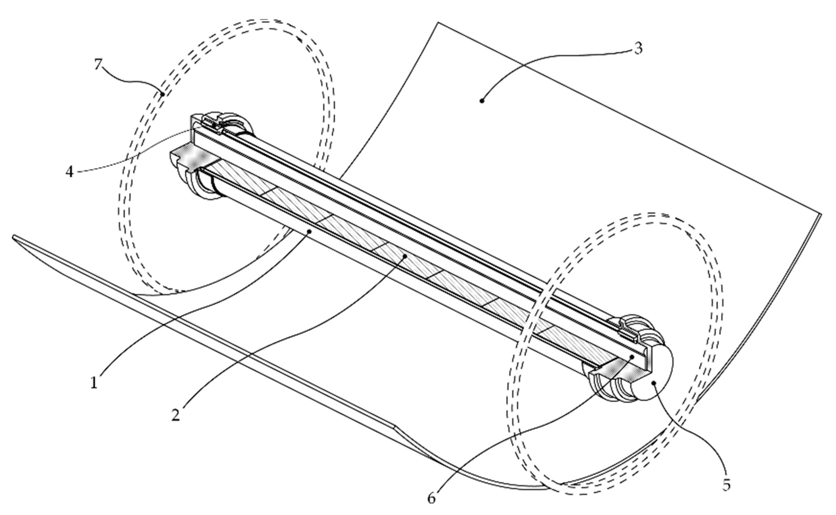
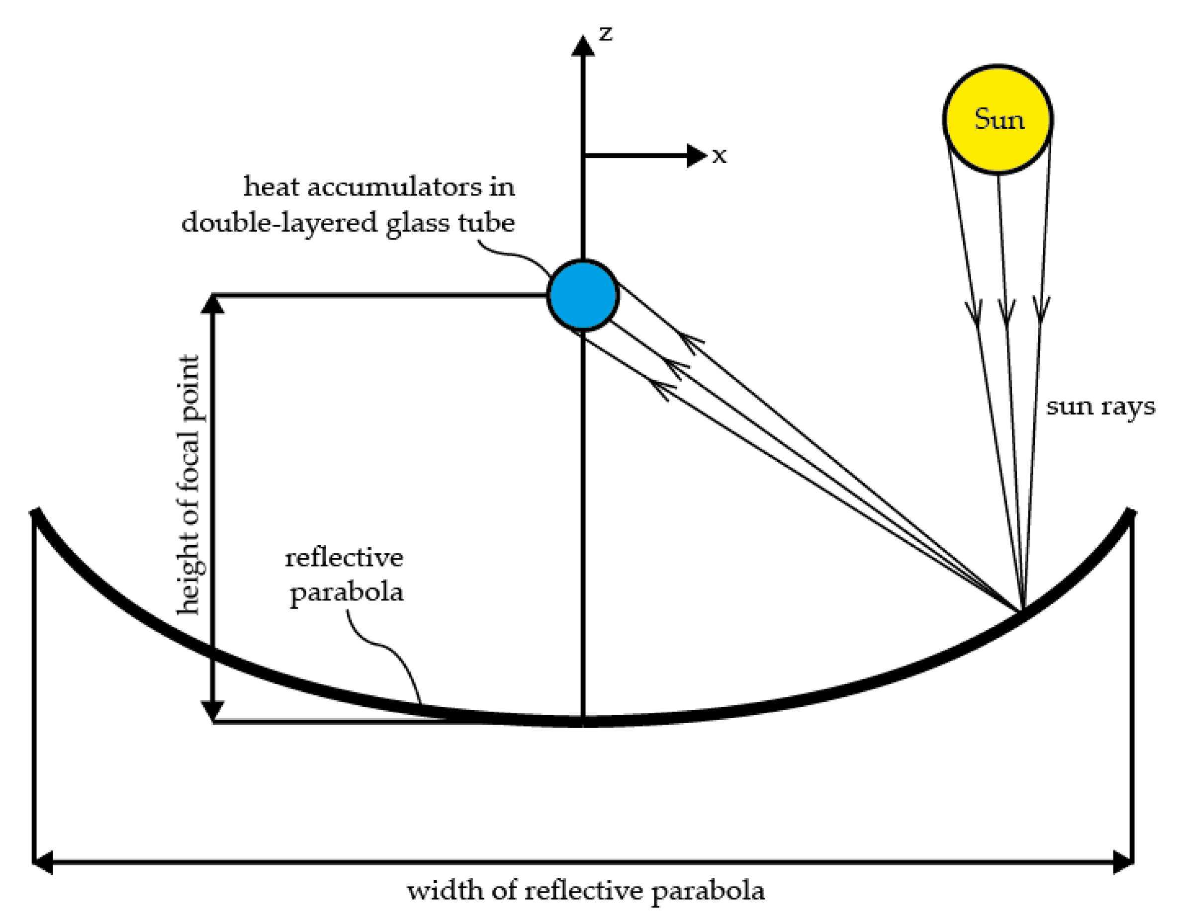
2.1. Concentrated Solar Heater for Segmental Heat Accumulators
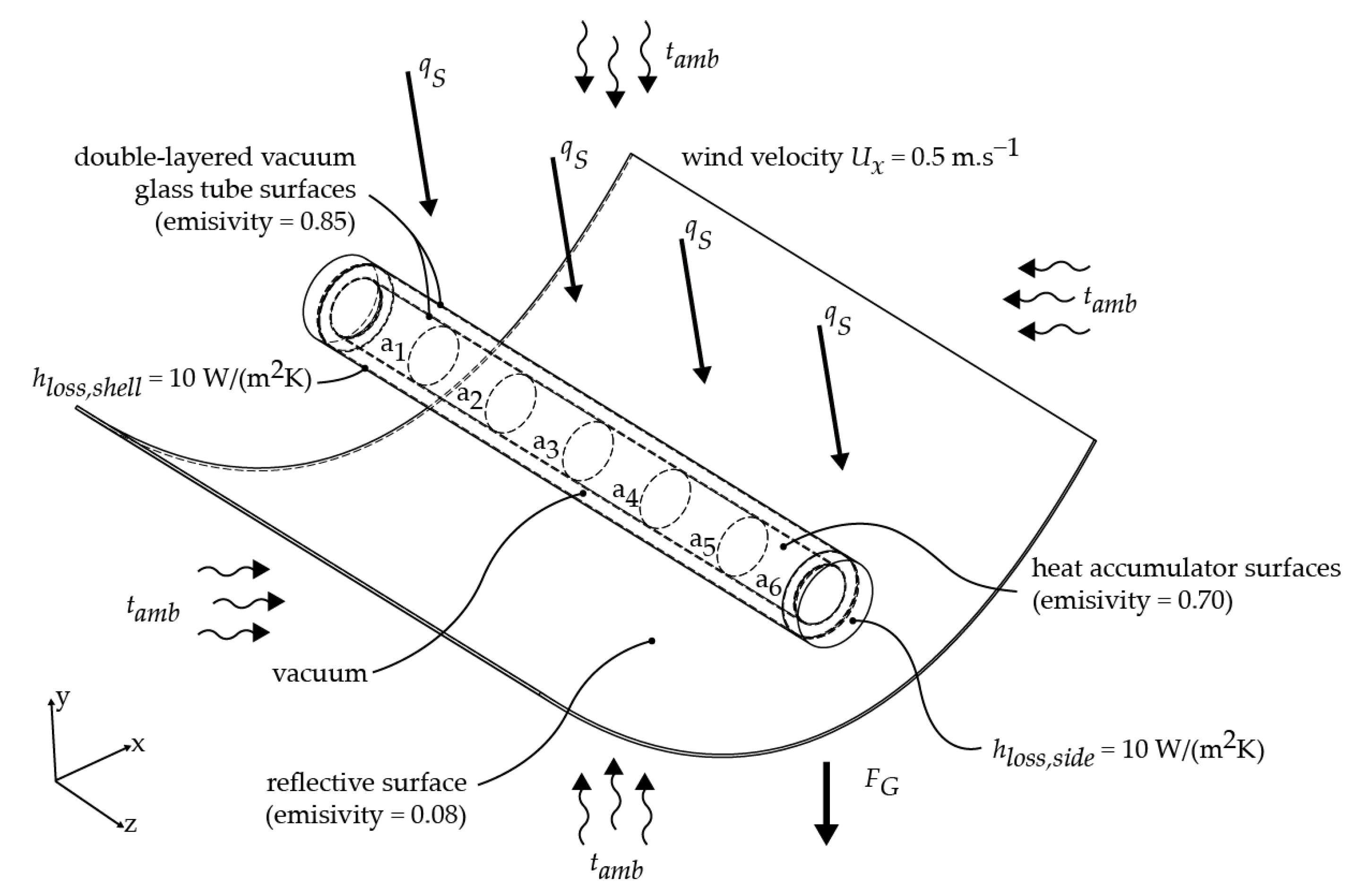
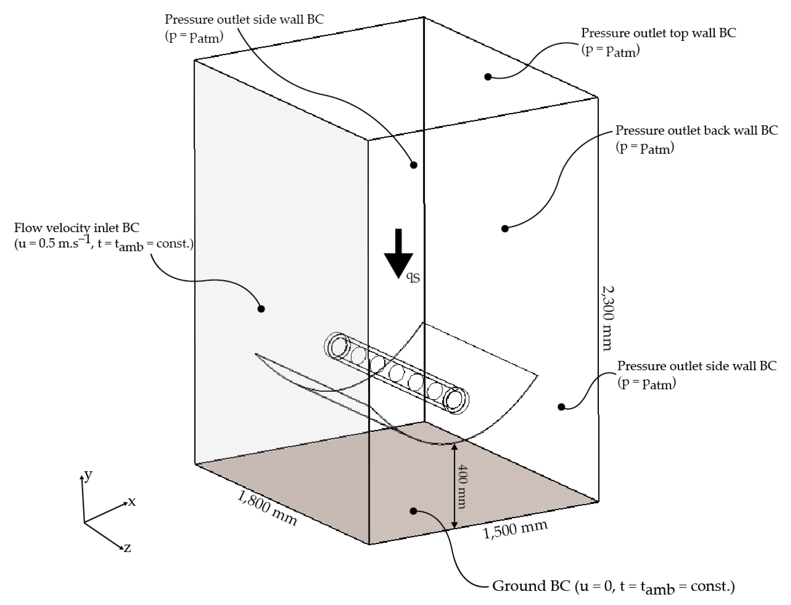
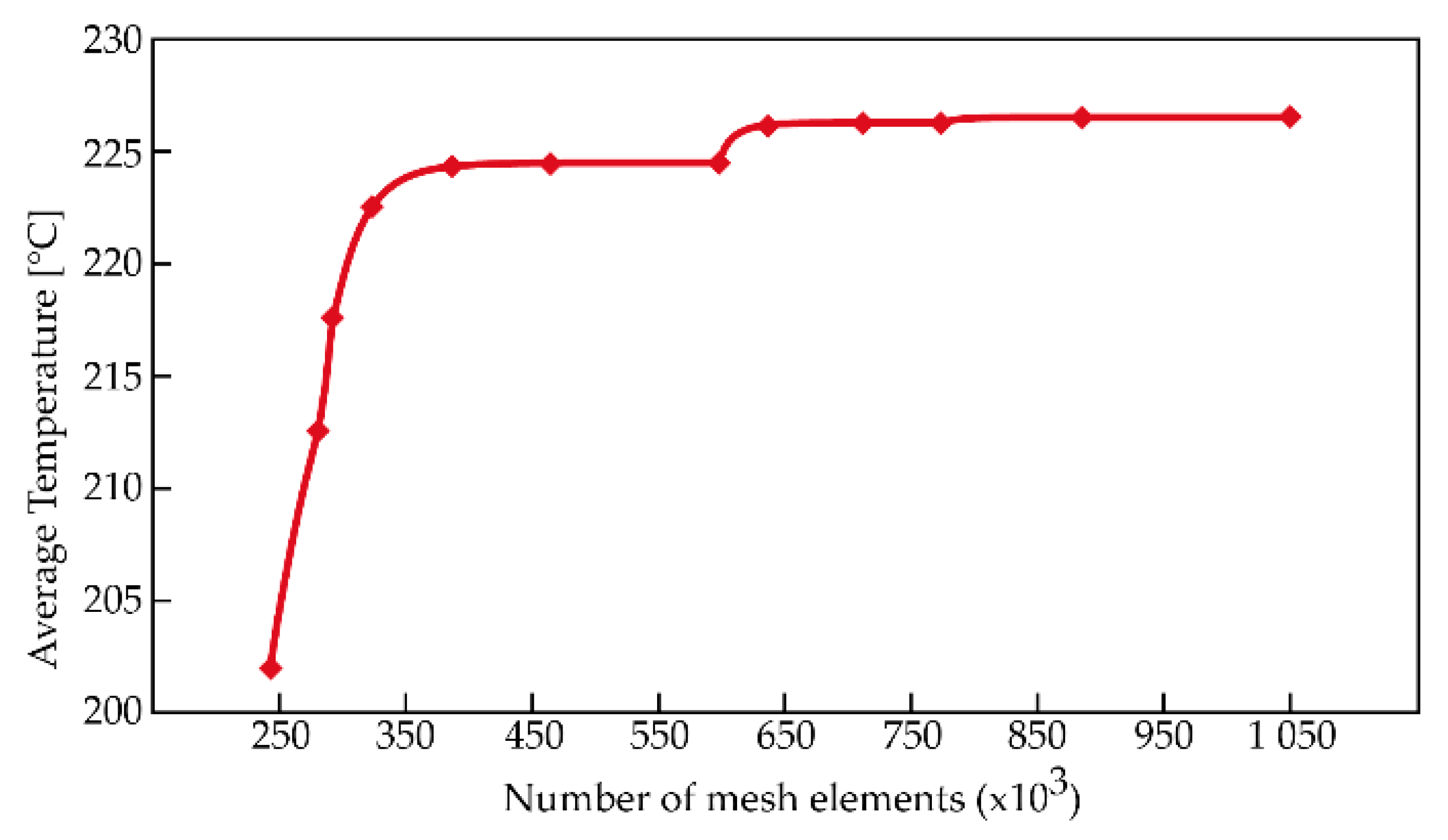
2.2. Methodology
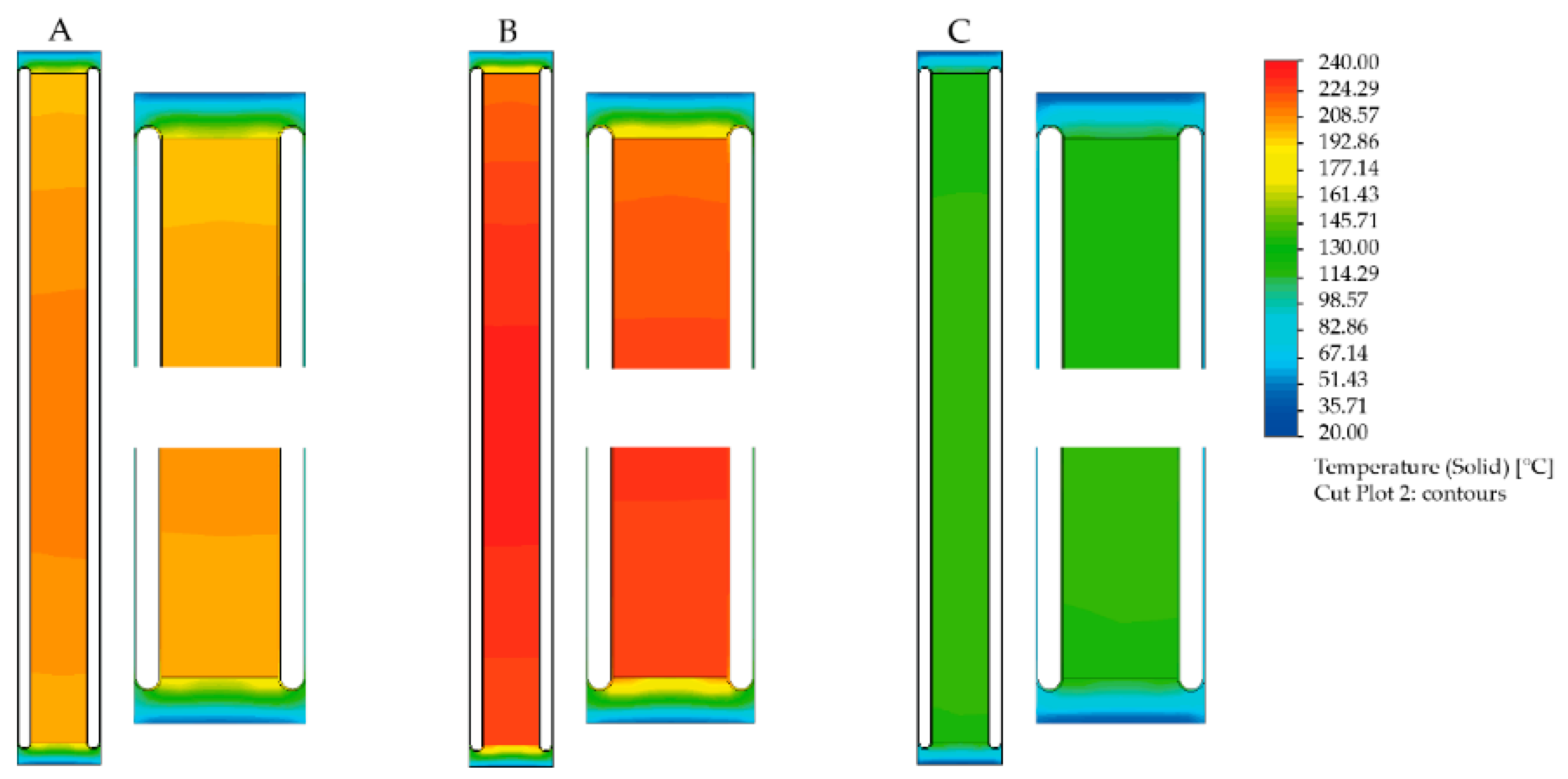
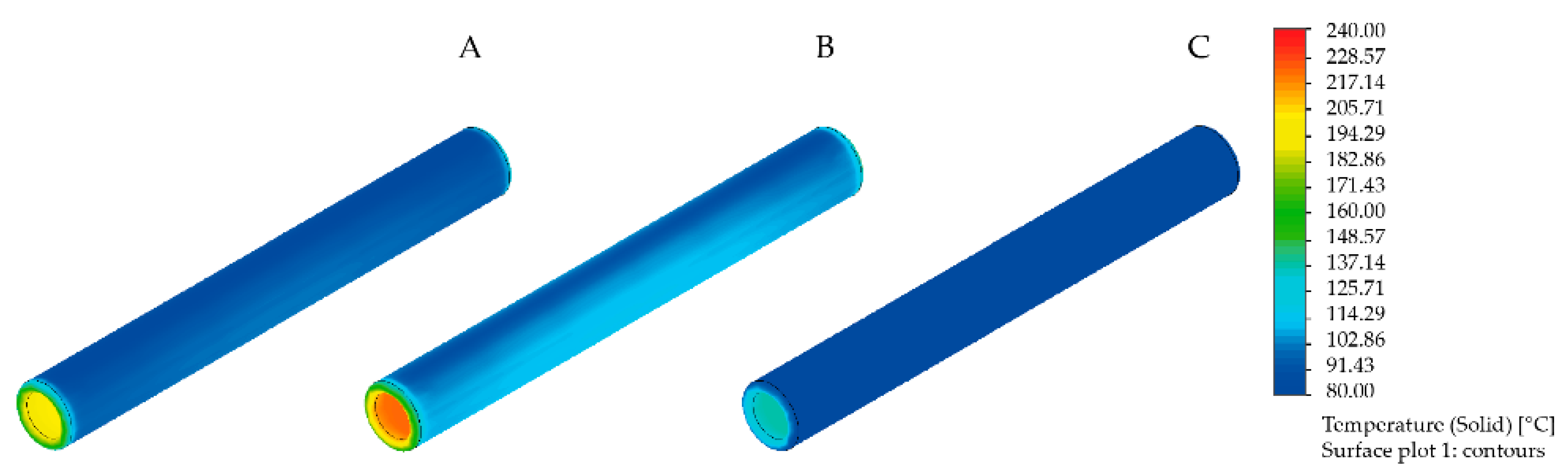
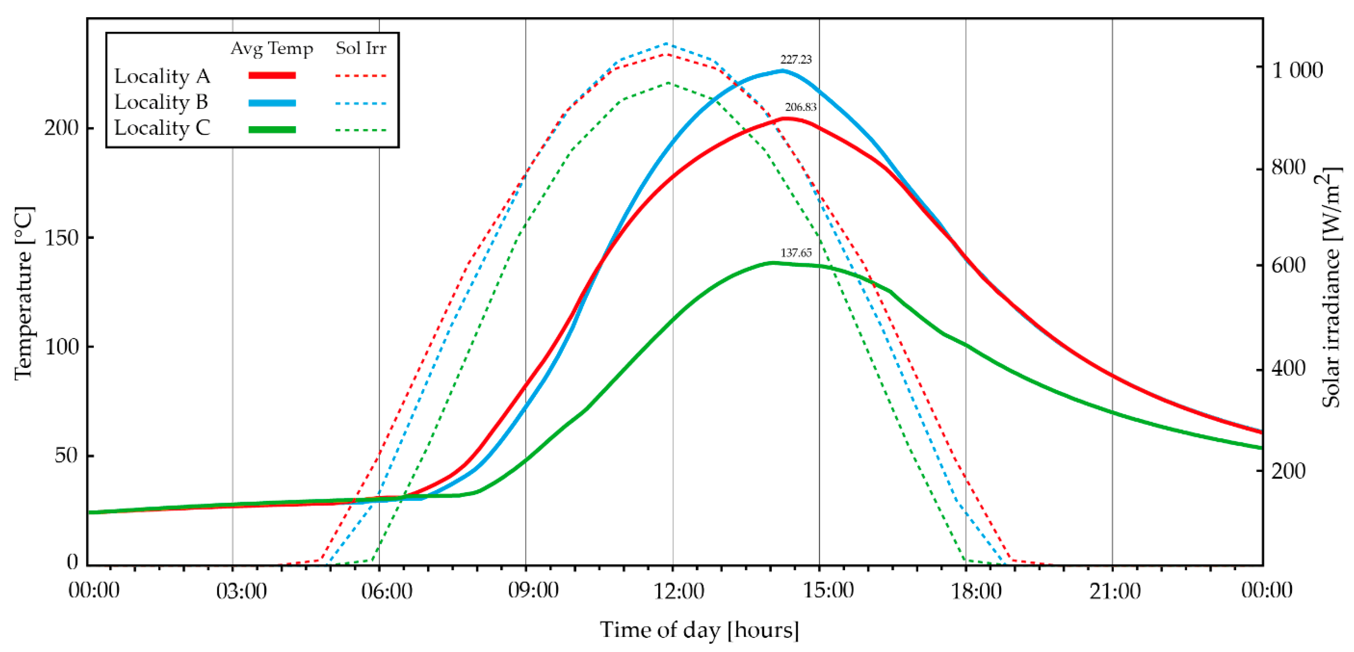
3. Results
4. Discussion
5. Conclusions
Author Contributions
Funding
Institutional Review Board Statement
Informed Consent Statement
Conflicts of Interest
References
- Liu, W.; Hou, Y.; Liu, W.; Yang, M.; Yan, Y.; Peng, C.; Yu, Z. Global estimation of the climate change impact of logging residue utilization for biofuels. For. Ecol. Manag. 2020, 462, 118000. [Google Scholar] [CrossRef]
- Wang, X.; Xu, L.; Cui, S.; Wang, C.-H. Reflections on coastal inundation, climate change impact, and adaptation in built environment: Progresses and constraints. Adv. Clim. Chang. Res. 2020, 11, 317–331. [Google Scholar] [CrossRef]
- Zhao, X.; Huang, G.; Lu, C.; Zhou, X.; Li, Y. Impacts of climate change on photovoltaic energy potential: A case study of China. Appl. Energy 2020, 280, 115888. [Google Scholar] [CrossRef]
- Yang, Y.C.E.; Son, K.; Hung, F.; Tidwell, V. Impact of climate change on adaptive management decisions in the face of water scarcity. J. Hydrol. 2020, 588, 125015. [Google Scholar] [CrossRef]
- Macusi, E.D.; Macusi, E.S.; Jimenez, L.A.; Catam-isan, J.P. Climate change vulnerability and perceived impacts on small-scale fisheries in eastern Mindanao. Ocean. Coast. Manag. 2020, 189, 105143. [Google Scholar] [CrossRef]
- Li, R.; Leung, G.C.K. The relationship between energy prices, economic growth and renewable energy consumption: Evidence from Europe. Energy Rep. 2021, 7, 1712–1719. [Google Scholar] [CrossRef]
- Jun, W.; Mughal, N.; Zhao, J.; Shabbir, M.S.; Niedbała, G.; Jain, V.; Anwar, A. Does globalization matter for environmental degradation? Nexus among energy consumption, economic growth, and carbon dioxide emission. Energy Policy 2021, 153, 112230. [Google Scholar] [CrossRef]
- Meng, J.; Hu, X.; Chen, P.; Coffman, D.; Han, M. The unequal contribution to global energy consumption along the supply chain. J. Environ. Manag. 2020, 268, 110701. [Google Scholar] [CrossRef] [PubMed]
- Inchauspe, J.; Li, J.; Park, J. Seasonal patterns of global oil consumption: Implications for long term energy policy. J. Policy Model. 2020, 42, 536–556. [Google Scholar] [CrossRef]
- BP Plc. BP Statistical Review of World Energy 2020; BP Plc: London, UK, 2020; pp. 8–11. [Google Scholar]
- U.S. Energy Information Administration. The Middle East, Africa, and Asia Now Drive Nearly All Global Energy Consumption Growth—International Energy Statistics 2020; U.S. Energy Information Administration: Washington, DC, USA, 2020; pp. 1–10. [Google Scholar]
- U.S. Energy Information Administration. International Energy Outlook 2020 (IEO2020); U.S. Energy Information Administration: Washington, DC, USA, 2020; pp. 1–7. [Google Scholar]
- Cehlár, M.; Teplická, K.; Seňová, A. Risk management as instrument for financing projects in mining industry. In Proceedings of the 11th International Multidisciplinary Scientific Geoconference and EXPO—Modern Management of Mine Producing, Geology and Environmental Protection, SGEM 2011, Varna, Bulgaria, 20–25 June 2011; Volume 1, pp. 913–920. [Google Scholar]
- Hrehová, D.; Cehlár, M.; Rybár, R.; Mitterpachová, N. Mining technology with drilling-blasting operations. In Proceedings of the 12th International Multidisciplinary Scientific GeoConference and EXPO—Modern Management of Mine Producing, Geology and Environmental Protection, SGEM 2012, Varna, Bulgaria, 17–23 June 2012; Volume 1, pp. 675–682. [Google Scholar]
- Batchelor, S.; Talukder, M.A.R.; Uddin, M.R.; Mondal, S.K.; Islam, S.; Redoy, R.K.; Hanlin, R.; Khan, M.R. Solar e-Cooking: A Proposition for Solar Home System Integrated Clean Cooking. Energies 2018, 11, 2933. [Google Scholar] [CrossRef] [Green Version]
- Cravioto, J.; Ohgaki, H.; Che, H.S.; Tan, C.; Kobayashi, S.; Toe, H.; Long, B.; Oudaya, E.; Rahim, N.A.; Farzeneh, H. The Effects of Rural Electrification on Quality of Life: A Southeast Asian Perspective. Energies 2020, 13, 2410. [Google Scholar] [CrossRef]
- World Health Organization. Burning Opportunity: Clean Household Energy for Health, Sustainable development, and Wellbeing of Women and Child; World Health Organization: Geneva, Switzerland, 2016; p. 9. [Google Scholar]
- Malla, S.; Timilsina, G.R. Household Cooking Fuel Choice and Adoption of Improved Cookstoves in Developing Countries; The World Bank Development Research Group: Washington, DC, USA, 2014. [Google Scholar]
- Anwar, M.A.; Nasreen, S.; Tiwari, A.K. Forestation, renewable energy and environmental quality: Empirical evidence from Belt and Road Initiative economies. J. Environ. Manag. 2021, 291, 112684. [Google Scholar] [CrossRef] [PubMed]
- Manolis, E.N.; Zagas, T.D.; Karetsos, G.K.; Poravou, C.A. Ecological restrictions in forest biomass extraction for a sustainable renewable energy production. Renew. Sustain. Energy Rev. 2019, 110, 290–297. [Google Scholar] [CrossRef]
- Galik, C.S.; Benedum, M.E.; Kauffman, M.; Becker, D.R. Opportunities and barriers to forest biomass energy: A case study of four U.S. states. Biomass Bioenergy 2021, 148, 106035. [Google Scholar] [CrossRef]
- Balmes, J.R. Household air pollution from domestic combustion of solid fuels and health. J. Allergy Clin. Immunol. 2019, 143, 1979–1987. [Google Scholar] [CrossRef]
- Li, Y.; Xu, H.; Wang, J.; Hang Ho, S.S.; He, K.; Shen, Z.; Ning, Z.; Sun, J.; Li, L.; Lei, R.; et al. Personal exposure to PM2.5-bound organic species from domestic solid fuel combustion in rural Guanzhong Basin, China: Characteristics and health implication. Chemosphere 2019, 227, 53–62. [Google Scholar] [CrossRef] [PubMed]
- Wang, D.; Li, Q.; Shen, G.; Deng, J.; Zhou, W.; Hao, J.; Jiang, J. Significant ultrafine particle emissions from residential solid fuel combustion. Sci. Total. Environ. 2020, 715, 136992. [Google Scholar] [CrossRef]
- Du, W.; Yun, X.; Fu, N.; Qi, M.; Wang, W.; Wang, L.; Chen, Y.; Shen, G. Variation of indoor and outdoor carbonaceous aerosols in rural homes with strong internal solid fuel combustion sources. Atmos. Pollut. Res. 2020, 11, 992–999. [Google Scholar] [CrossRef]
- Ezzati, M.; Kammen, D.M. The Health Impacts of Exposure to Indoor Air Pollution from Solid Fuels in Developing Countries: Knowledge, Gaps, and Data Needs. Environ. Health Perspect. 2002, 110, 1057–1068. [Google Scholar] [CrossRef] [Green Version]
- Ray, I.; Smith, K.R. Towards safe drinking water and clean cooking for all. Lancet Glob. Health 2021, 9, 361–365. [Google Scholar] [CrossRef]
- Quinn, A.K.; Bruce, N.; Puzzolo, E.; Dickinson, K.; Sturke, R.; Jack, D.W.; Mehta, S.; Shankar, A.; Sherr, K.; Rosenthal, J.P. An analysis of efforts to scale up clean household energy for cooking around the world. Energy Sustain. Dev. 2018, 46, 1–10. [Google Scholar] [CrossRef]
- Rosenthal, J.; Quinn, A.; Grieshop, A.P.; Pillarisetti, A.; Glass, R.I. Clean cooking and the SDGs: Integrated analytical approaches to guide energy interventions for health and environment goals. Energy Sustain. Dev. 2018, 42, 152–159. [Google Scholar] [CrossRef]
- Neto-Bradley, A.P.; Rangarajan, R.; Choudhary, R.; Bazaz, A. A clustering approach to clean cooking transition pathways for low-income households in Bangalore. Sustain. Cities Soc. 2021, 66, 102697. [Google Scholar] [CrossRef]
- Aemro, Y.B.; Moura, P.; de Almeida, A.T. Experimental evaluation of electric clean cooking options for rural areas of developing countries. Sustain. Energy Technol. Assess. 2021, 43, 100954. [Google Scholar]
- Kajumba, P.K.; Okello, D.; Nyeinga, K.; Nydal, O.J. Experimental investigation of a cooking unit integrated with thermal energy storage system. J. Energy Storage 2020, 32, 101949. [Google Scholar] [CrossRef]
- Solar Cooker Distribution—S.C.I. Available online: http://www.solarcookers.org/our-work/solar-cooker-distribution/ (accessed on 3 June 2020).
- Arunachala, U.C.; Kundapur, A. Cost-effective solar cookers: A global review. Sol. Energy 2020, 207, 903–916. [Google Scholar] [CrossRef]
- Rodríguez Morales, J.Á.; González-Avilés, M.; Servín Campuzano, H.; Masera, O. T’imani a Multifunctional Solar System to Provide Cooking and Water Heating Rural Energy Needs. Energies 2020, 13, 3429. [Google Scholar] [CrossRef]
- Zafar, H.A.; Badar, A.W.; Butt, F.S.; Khan, M.Y.; Siddiqui, M.S. Numerical modeling and parametric study of an innovative solar oven. Sol. Energy 2019, 87, 411–426. [Google Scholar] [CrossRef]
- Ayub, I.; Nasir, M.S.; Liu, Y.; Munir, A.; Yang, F.; Zhang, Z. Performance improvement of solar bakery unit by integrating with metal hydride based solar thermal energy storage reactor. Renew. Energy 2020, 161, 1011–1024. [Google Scholar] [CrossRef]
- Bhave, A.G.; Kale, C.K. Development of a thermal storage type solar cooker for high temperature cooking using solar salt. Sol. Energy Mater. Sol. Cells 2020, 208, 110394. [Google Scholar] [CrossRef]
- Kumaresan, G.; Santosh, R.; Raju, G.; Velraj, R. Experimental and numerical investigation of solar flat plate cooking unit for domestic applications. Energy 2018, 157, 436–447. [Google Scholar] [CrossRef]
- Sagade, A.A.; Samdarshi, S.K.; Lahkar, P.J.; Sagade, N.A. Experimental determination of the thermal performance of a solar box cooker with a modified cooking pot. Renew. Energy 2020, 150, 1001–1009. [Google Scholar] [CrossRef]
- Mawire, A.; Lentswe, K.; Owusu, P.; Shobo, A.; Darkwa, J.; Calautit, J.; Worall, M. Performance comparison of two solar cooking storage pots combined with wonderbag slow cookers for off-sunshine cooking. Sol. Energy 2020, 208, 1166–1180. [Google Scholar] [CrossRef]
- Chaudhary, R.; Yadav, A. Twin vessel solar cook stove for the simultaneous cooking of two different cooking articles. Sol. Energy 2020, 208, 688–696. [Google Scholar] [CrossRef]
- Hosseinzadeh, M.; Faezian, A.; Mirzababaee, S.M.; Zamani, H. Parametric analysis and optimization of a portable evacuated tube solar cooker. Energy 2020, 197, 116816. [Google Scholar] [CrossRef]
- Radim Rybár, R.; Kudelas, D.; Beer, M.; Horodníková, J. Elimination of Thermal Bridges in the Construction of a Flat Low-Pressure Solar Collector by Means of a Vacuum Thermal Insulation Bushing. J. Sol. Energy Eng. 2015, 137, 054501. [Google Scholar] [CrossRef]
- Iqbal, M. An Introduction to Solar Radiation; Academic Press: Toronto, ON, Canada, 1983; pp. 303–334. [Google Scholar]
- Bird, R.E.; Hulstrom, R.L. A Simplified Clear Sky Model for Direct and Diffuse Insolation on Horizontal Surface; Solar Energy Research Institute: Golden, CO, USA, 1981; p. 46. [Google Scholar]
- Badescu, V. Modeling Solar Radiation at the Earth’s Surface; Springer: Berlin, Germany, 2008; pp. 93–113. [Google Scholar]
- Dassault Systemes. Solidworks Flow Simulations Technical Reference; Dassault Systemes: Vélizy-Villacoublay, France, 2017. [Google Scholar]
- Sobachkin, A.; Dumnov, G. Numerical Basis of CAD-Embedded CFD; Solidworks Technical Reference; Dassault Systems: Vélizy-Villacoublay, France, 2017. [Google Scholar]
- Cengel, Y.; Boles, M. Thermodynamics: An Engineering Approach, 8th ed.; McGraw-Hill Education: New York, NY, USA, 2014. [Google Scholar]


| Material | Density [kg/m3] | Total Weight [kg] | Thermal Conductivity [W/(mK)] | Specific Heat Capacity [J/(kgK)] | |
|---|---|---|---|---|---|
| Heat accumulator | Cast iron | 7200 | 67.86 | 52 | 460 |
| Vacuum glass tube | Borosilicate glass | 2200 | 4.232 | 1.4 | 670 |
| Concentration- reflective parabola | Polished aluminum foil | 2700 | 0.120 | 237 | 900 |
| Thermal isolation block | Mineral glass wool | 130 | 0.156 | 0.035 | 1030 |
| The Maximum Intensity of Solar Radiation [W/m2] | Ambient Temperature [°C] | Latitude | The Average Temperature of the Heat Accumulators [°C] | The Average OuterSurface Temperature of the Vacuum Glass Tube [°C] | |
|---|---|---|---|---|---|
| Locality A (North Africa) | 1030 | 25.1 | 33° N | 206.83 | 94.55 |
| Locality B (South China) | 1045 | 25.6 | 23.5° N | 227.23 | 106.29 |
| Locality C (Indonesia) | 960 | 25.9 | 1° N | 137.65 | 62.99 |
Publisher’s Note: MDPI stays neutral with regard to jurisdictional claims in published maps and institutional affiliations. |
© 2021 by the authors. Licensee MDPI, Basel, Switzerland. This article is an open access article distributed under the terms and conditions of the Creative Commons Attribution (CC BY) license (https://creativecommons.org/licenses/by/4.0/).
Share and Cite
Beer, M.; Rybár, R.; Rybárová, J.; Seňová, A.; Ferencz, V. Numerical Analysis of Concentrated Solar Heaters for Segmented Heat Accumulators. Energies 2021, 14, 4350. https://doi.org/10.3390/en14144350
Beer M, Rybár R, Rybárová J, Seňová A, Ferencz V. Numerical Analysis of Concentrated Solar Heaters for Segmented Heat Accumulators. Energies. 2021; 14(14):4350. https://doi.org/10.3390/en14144350
Chicago/Turabian StyleBeer, Martin, Radim Rybár, Jana Rybárová, Andrea Seňová, and Vojtech Ferencz. 2021. "Numerical Analysis of Concentrated Solar Heaters for Segmented Heat Accumulators" Energies 14, no. 14: 4350. https://doi.org/10.3390/en14144350
APA StyleBeer, M., Rybár, R., Rybárová, J., Seňová, A., & Ferencz, V. (2021). Numerical Analysis of Concentrated Solar Heaters for Segmented Heat Accumulators. Energies, 14(14), 4350. https://doi.org/10.3390/en14144350