
Hydrodynamics and Mass Transfer in a Concentric Internal Jet-Loop Airlift Bioreactor Equipped with a Deflector


Abstract
:1. Introduction
1.1. Algae Potential
1.2. Microalgae Cultivation
1.3. Internal-Loop Airlift Reactor
1.4. Main Operational Parameters
1.4.1. Total Gas Holdup
1.4.2. Homogenization Time
1.4.3. Overall Volumetric Mass Transfer Coefficient kLa
1.4.4. Effect of Solid Phase
1.5. Motivation
2. Materials and Methods
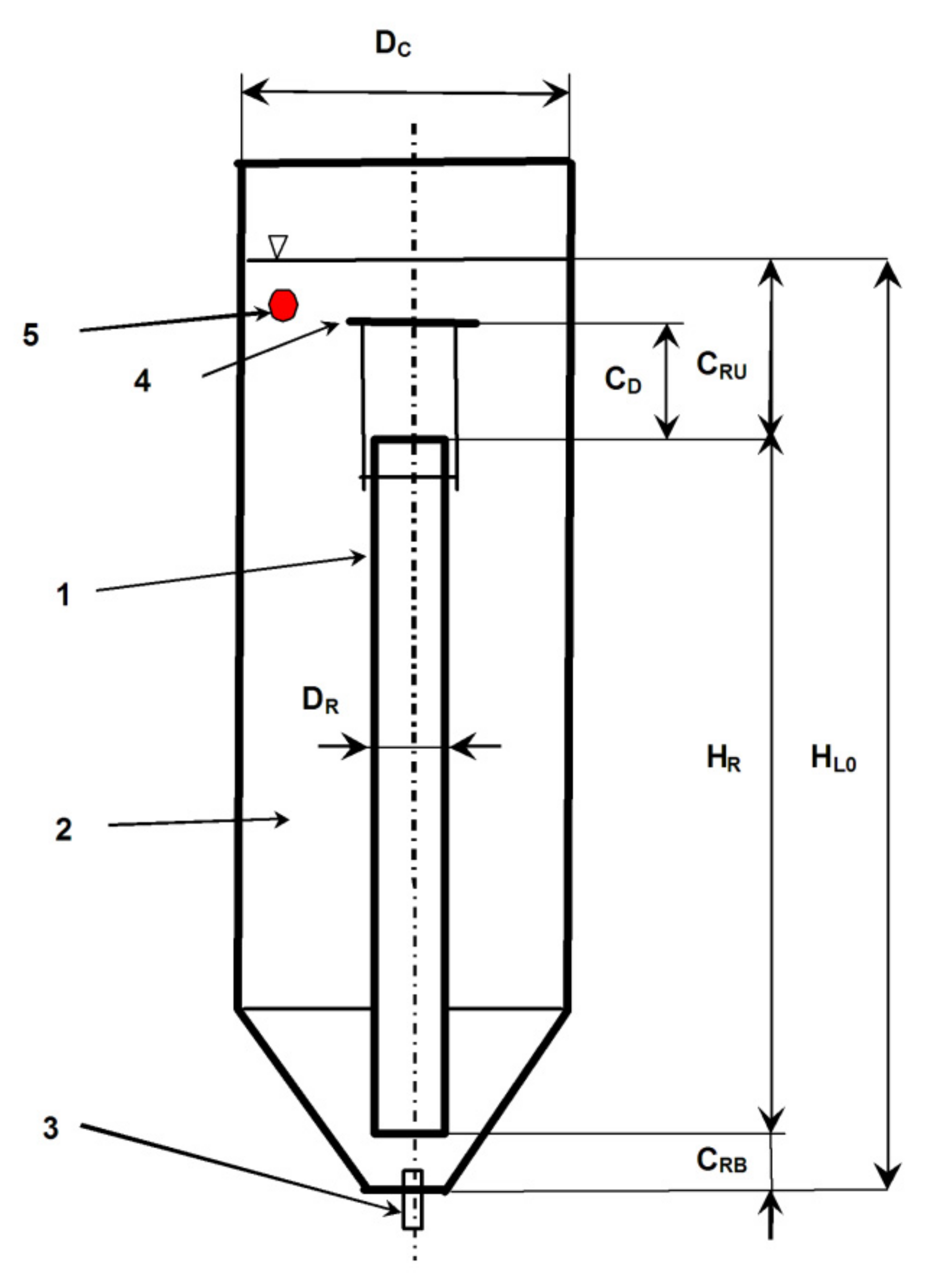
2.1. Experimental Apparatus
2.2. Experimental Conditions
2.3. Experimental Methods
2.3.1. Total Gas Holdup
2.3.2. Homogenization Time
2.3.3. Overall Volumetric Liquid-Phase Mass Transfer Coefficient kLa
2.3.4. Statistical Analysis
- (i)
- average absolute error (AAE):
- (ii)
- average biased error (ABE):
- (iii)
- coefficient of determination (R2):where ypred,i is the property value predicted by proposed correlation, is the average of experimental property values. These three statistical criteria are employed to assess the applicability of proposed or tested correlations [58]. The average absolute error (AAE) measures the degree of closeness between the predicted and measured results [57]. A smaller value of AAE indicates higher accuracy of the proposed correlation [58]. The average biased error (ABE) indicates the degree of overestimation and underestimation of proposed or tested correlation [57]. The positive value of ABE indicates an overall overestimation, whereas a negative value of ABE indicates an overall underestimation [58]. The coefficient of determination (R2-value) is used to determine the degree of goodness and accuracy of proposed or tested correlation [57]. A higher R2-value indicates a better fitting quality of correlation used [58]. The proposed or tested correlation is considered the best fitting model if the AAE and ABE values tend to zero and R2-value is close to 1 [57].
3. Results
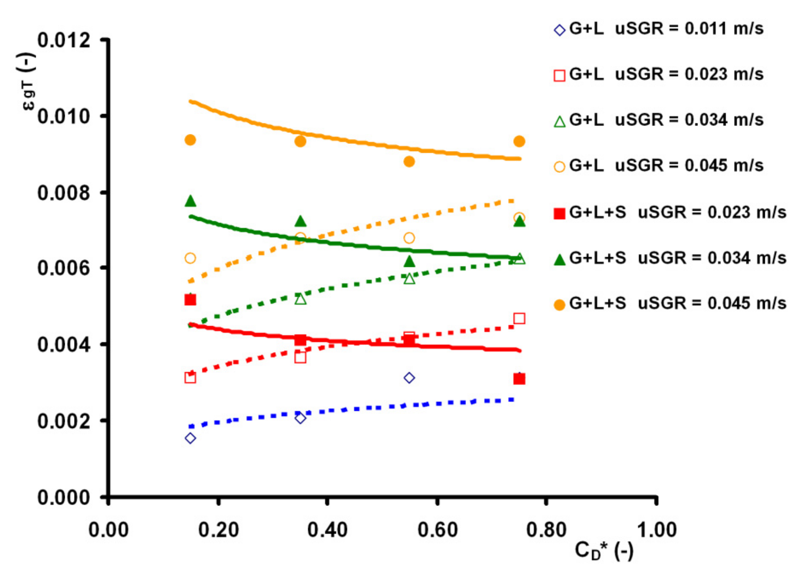
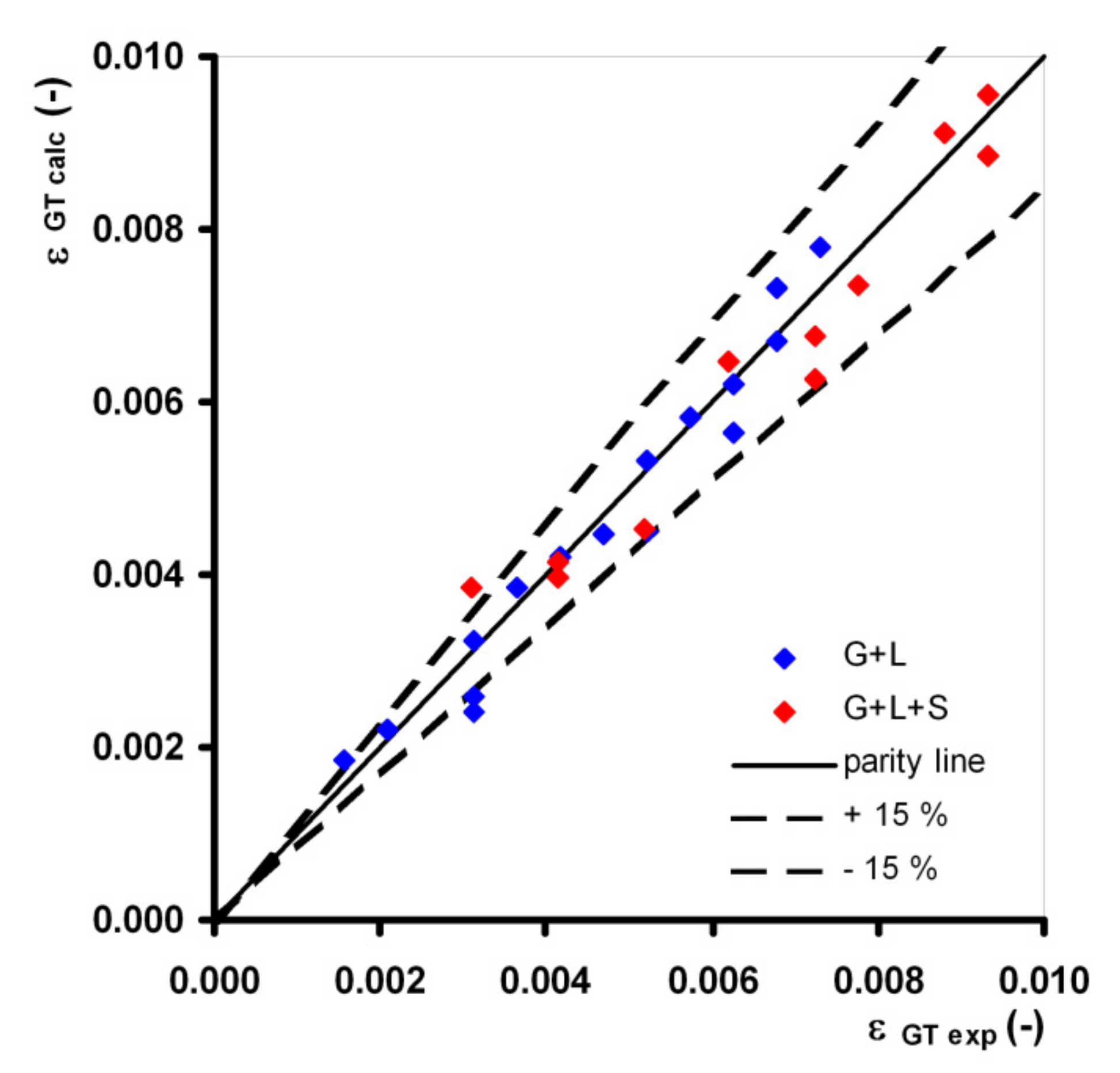
3.1. Total Gas Holdup
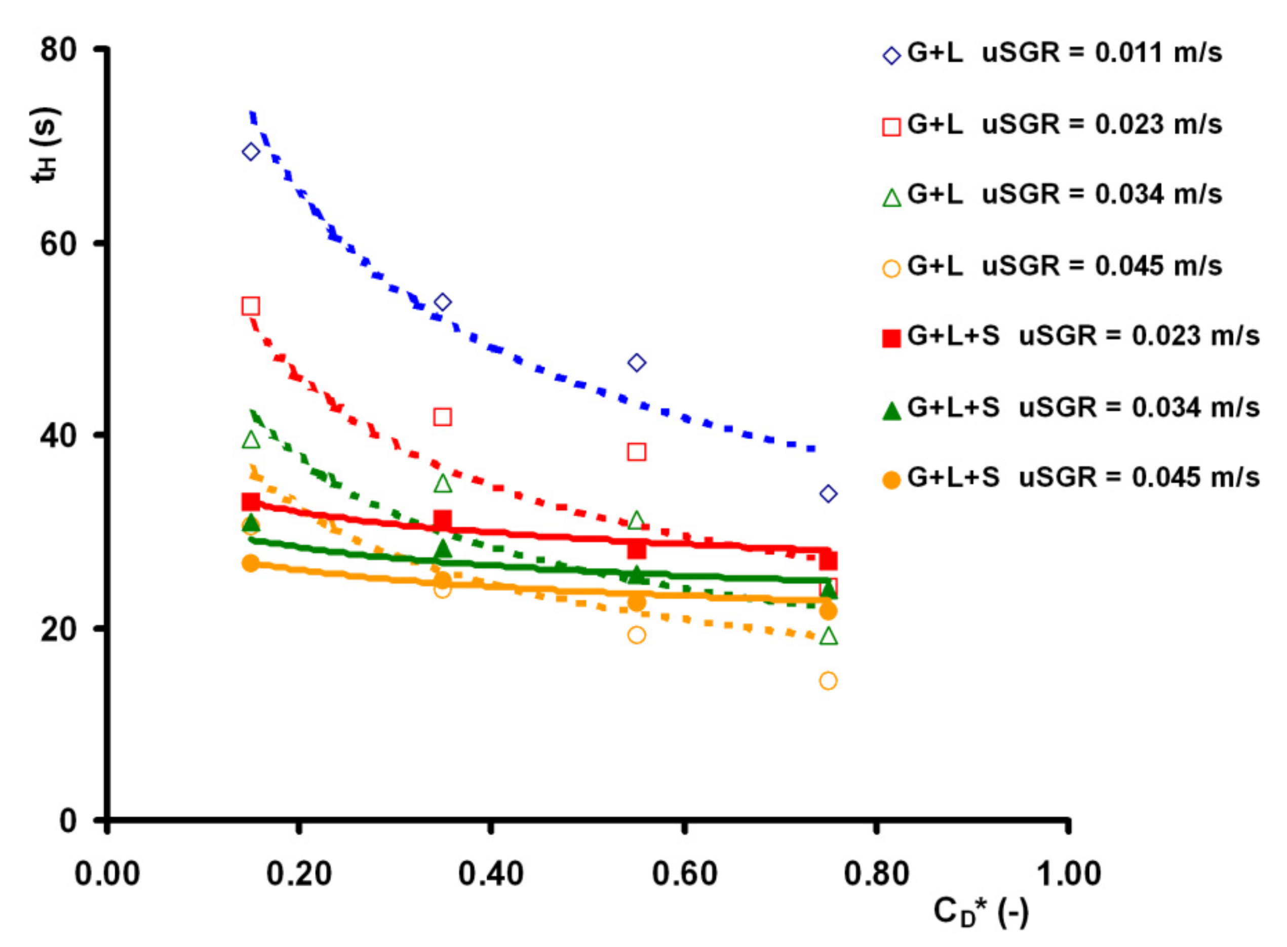
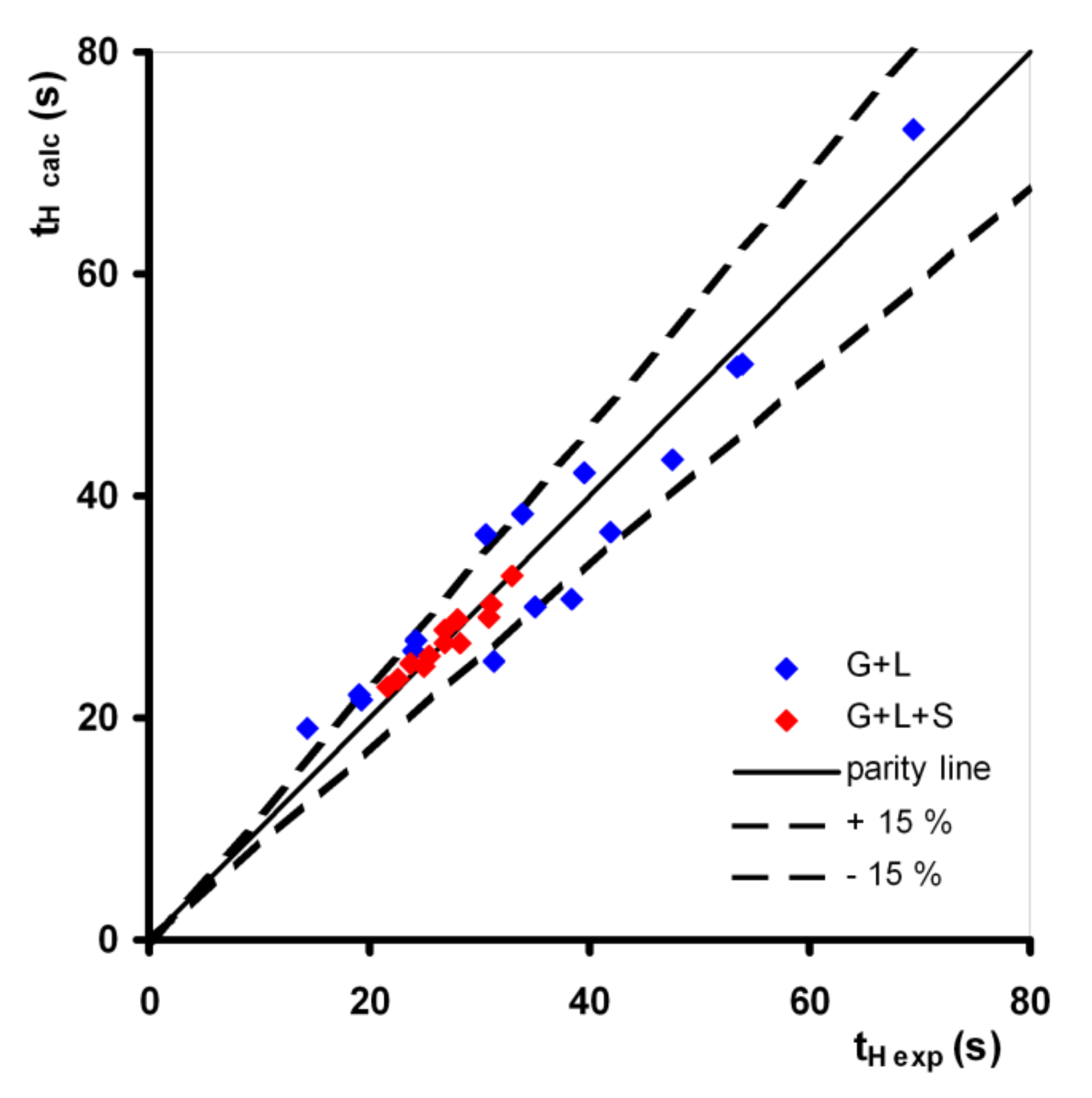
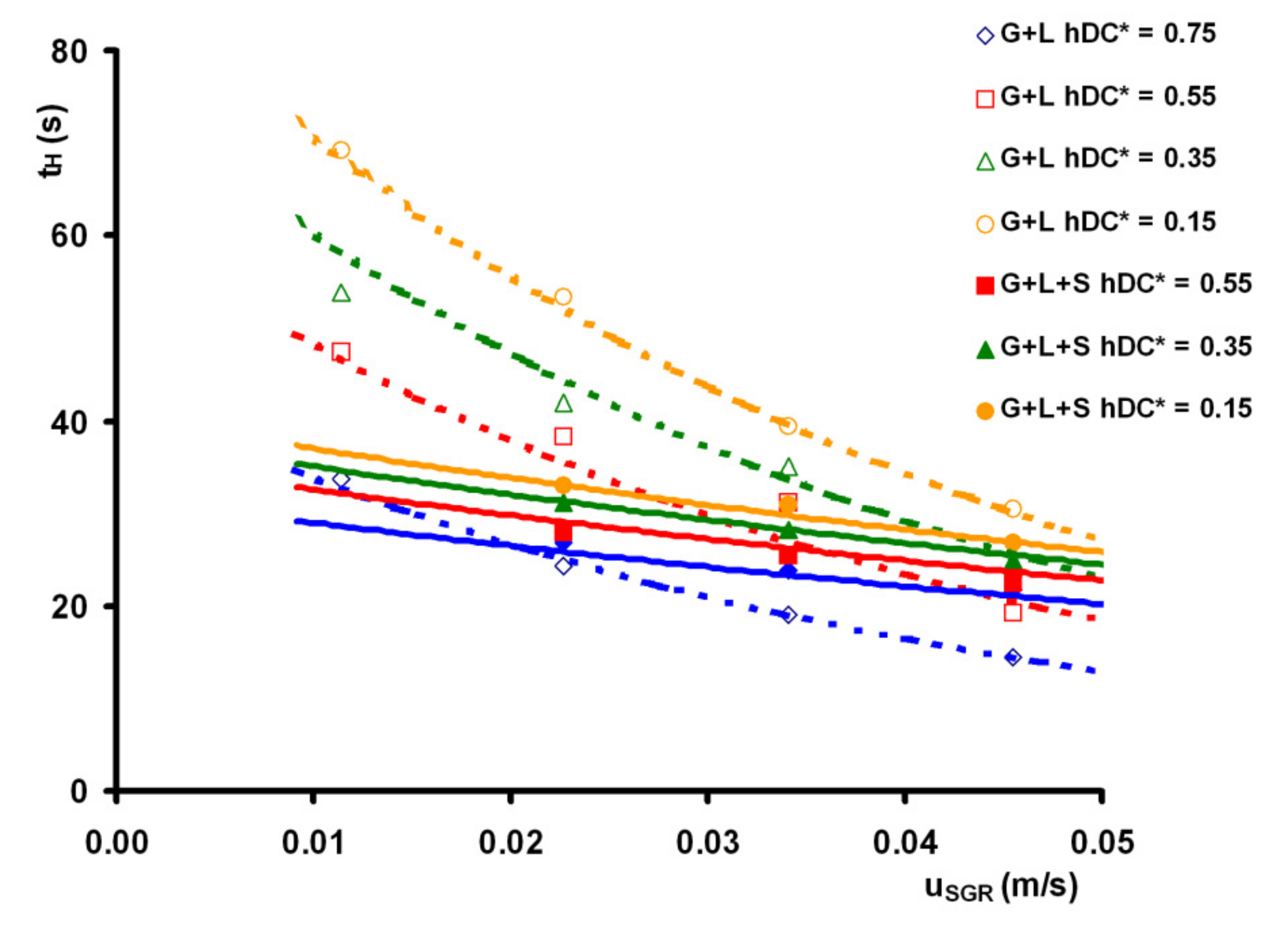
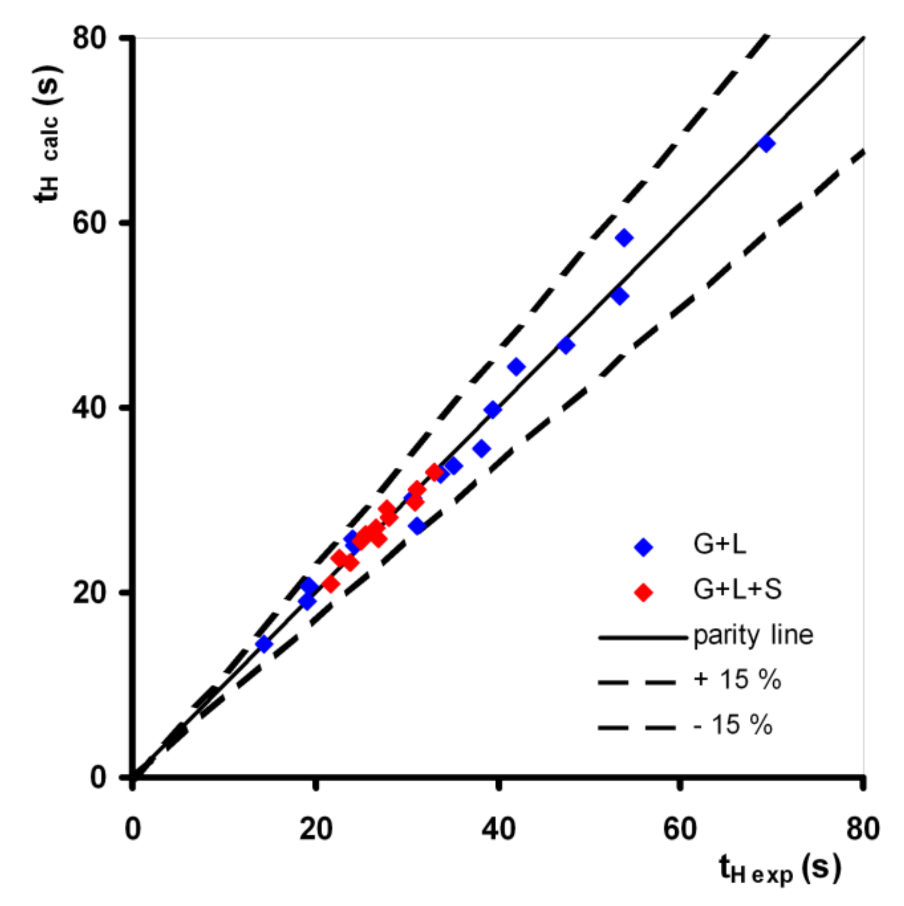
3.2. Homogenization Time tH
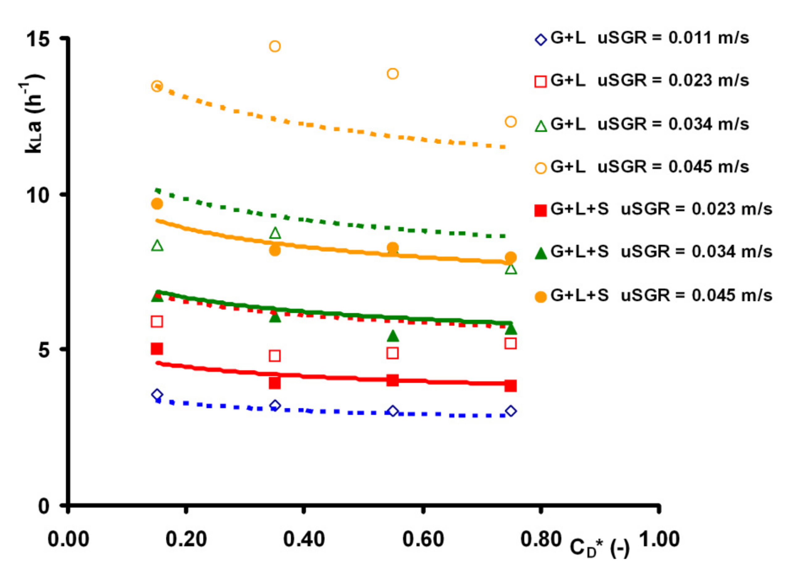
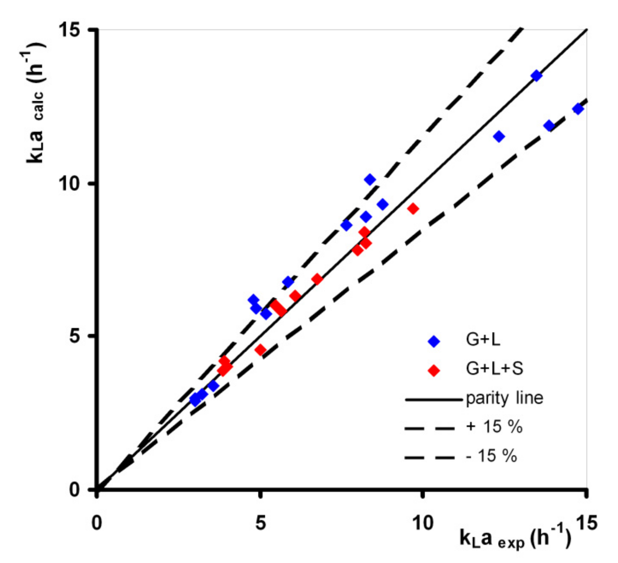
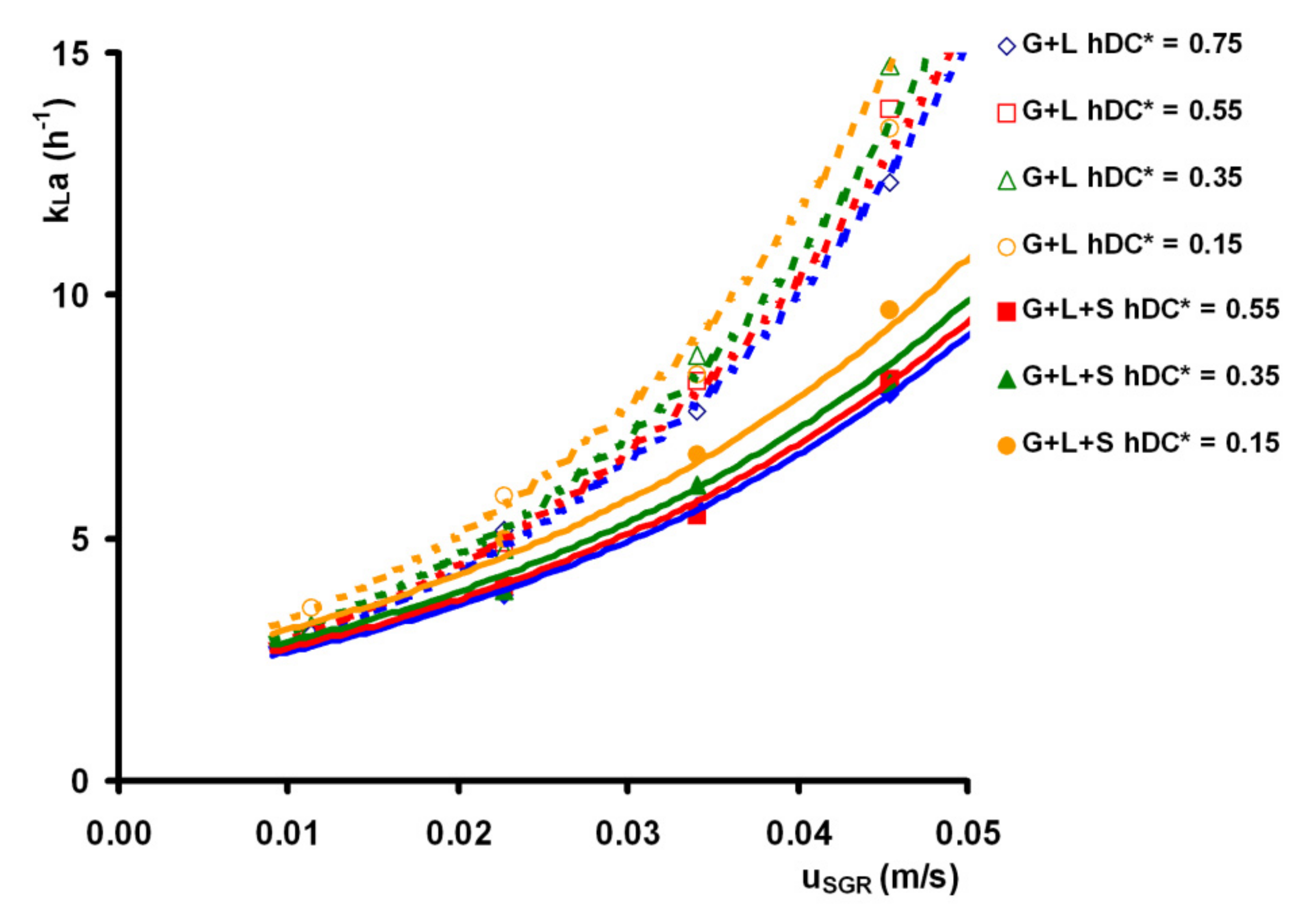
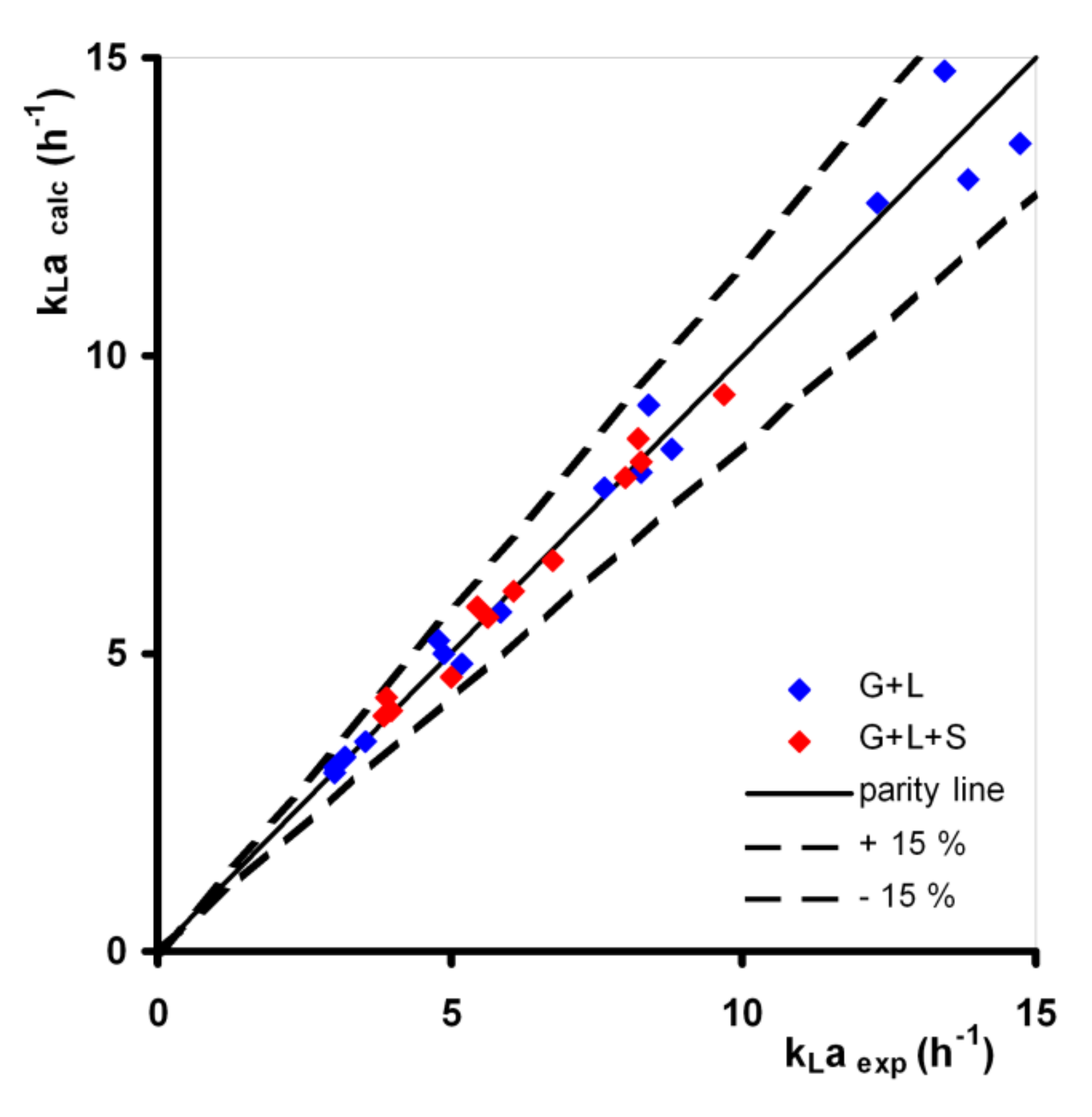
3.3. Overall Volumetric Liquid-Phase Mass Transfer Coefficient kLa
4. Conclusions
- Reducing the deflector clearance, the total gas holdup decreases for the gas–liquid system. Unlike this, the weak effect of deflector clearance was observed for the gas–liquid–solid system, especially for higher values of riser superficial gas velocity;
- For the gas–liquid system, when reducing deflector clearance, homogenization time increased twice compared to the highest deflector clearance tested. For the gas–liquid–solid system, the effect of deflector clearance is weaker compared to the gas–liquid system and the presence of solid phase shortens the homogenization time, especially for lower riser superficial gas velocity and deflector clearance;
- For the gas–liquid system, when reducing the deflector clearance, the overall volumetric mass transfer coefficient slightly increases by 10–17%. The presence of solid phase reduced the mass transfer coefficient by 15–35%. In the gas–liquid–solid system, the effect of deflector clearance is more accentuated compared to the gas–liquid system. The mass transfer coefficient for the lowest tested deflector clearance was approx. 20–29% higher than for the highest tested deflector clearance.
- The airlift reactors equipped with internals placed in the gas separation section may be a promising novel airlift reactor design, as reported by Zhang et al. [30].
Author Contributions
Funding
Conflicts of Interest
Nomenclature
| AAE | average absolute error | % |
| ABE | average bias error | % |
| AC | column cross-section area | m2 |
| AD | downcomer cross-section area | m2 |
| AR | riser cross-section area | m2 |
| Bo | Bond number; Bo = g⋅ρL⋅Dchar2/σ | - |
| BR | bottom spatial ratio; B = CRB/DR | - |
| cL | mass concentration of liquid dissolved oxygen | kg/m3 |
| mass concentration of dissolved oxygen in liquid at saturation | kg/m3 | |
| C | temperature correction factor in Equation (11) | - |
| C | constant of proportionality in Equation (4) | (m/s)-α |
| C | constant of proportionality in Equation (6) | s⋅(m/s)-α |
| C | constant of proportionality in Equation (7) | s |
| C | constant of proportionality in Equation (12) | h−1⋅(m/s)-α |
| C | constant of proportionality in Equation (13) | h−1 |
| CD | deflector clearance | m |
| CRB | riser bottom clearance | m |
| CRU | riser upper clearance | m |
| dh | hole diameter (in gas distributor) | m |
| DC | column inner diameter | m |
| Dchar | characteristic diameter (DR or DC) | m |
| DD | downcomer inner diameter | m |
| DL | diffusivity coefficient of gas in liquid | m2/s |
| DR | riser inner diameter | m |
| DS | gas separator inner diameter | m |
| DT | draft tube inner diameter | m |
| Fr | Froude number; Fr = uSG/(g⋅Dchar)0.5 | - |
| g | gravity acceleration | m/s2 |
| Ga | Galilei number; Ga = g⋅ρL2⋅Dchar3/μL2 | - |
| HL0 | liquid filling height | m |
| HG+L | height of gas–liquid dispersion | m |
| HG+L+S | height of gas–liquid–solid dispersion | m |
| HR | riser height | m |
| kLa | overall volumetric liquid-phase mass transfer coefficient | s−1 |
| Mo | Morton number; Mo = g⋅μL4/(ρL⋅σL3) | - |
| OTR | oxygen transfer rate | kg/(m3.s) |
| R | downcomer resistance flow ratio; R = AD/AR | - |
| R2 | coefficient of determination | - |
| SG | gas-to-liquid interfacial area | m2 |
| Sc | Schmidt number; Sc = μL/(ρL⋅DL) | - |
| Sh | Sherwood number; Sh = kLa⋅Dchar2/DL | - |
| t | time | s |
| T | temperature | °C |
| TR | top spatial ratio; T = CRU/DR + 1 | - |
| uSG | superficial gas velocity (for riser or column) | m/s |
| uSGC | column superficial gas velocity (based on the column cross-section); /AC | m/s |
| uSGR | riser superficial gas velocity (based on the riser cross-section); /AR | m/s |
| V | volume | m3 |
| gas volumetric flowrate | m3/s | |
| Y | gas separator ratio; Y = (CRU + DR)/DS | - |
Greek Letters
| α | power-law exponent in Equations (4), (6), and (12) | - |
| α | power-law exponent in Equations (7) and (13) | s/m |
| α | significance level | - |
| β | power-law exponent in Equations (4), (6), (7), (12), and (13) | - |
| ε | gas hold up | - |
| φS | volumetric solid fraction | - |
| μL | dynamic viscosity of liquid | Pa.s |
| υ | kinematic viscosity | m2/s |
| ρ | density | kg/m3 |
| σ | surface tension | N/m |
| τ | response time of oxygen probe | s |
Indexes
| B | bottom |
| C | column |
| calc | calculated |
| D | downcomer |
| G | gas phase |
| L | liquid phase |
| pred | predicted |
| R | riser |
| S | gas separator |
| S | solid phase |
| T | draft tube |
| T | total |
| U | upper |
Abbreviation
| ALR | airlift reactor |
References
- Lafarga, T.; Acién-Fernández, F.G.; Garcia-Vaquero, M. Bioactive peptides and carbohydrates from seaweed for food applications: Natural occurrence, isolation, purification, and identification. Algal Res. 2020, 48, 101909. [Google Scholar] [CrossRef]
- Papacek, S.; Petera, K.; Masaló, I.; Oca, J. Modeling and optimization of flow pattern in tanks for seaweed culture. In Proceedings of the Aquaculture Europe 2017: Cooperation for Growth—Abstracts EA2017, Dubrovnik, Croatia, 7–20 October 2017; European Aquaculture Society: Oostende, Belgium, 2017; p. 874. [Google Scholar]
- Dolganyuk, V.; Belova, D.; Babich, D.; Prosekov, A.; Ivanova, S.; Katserov, D.; Patyukov, N.; Sukhikh, S. Microalgae: A Promising Source of Valuable Bioproducts. Biomolecules 2020, 10, 1153. [Google Scholar] [CrossRef] [PubMed]
- Guedes, A.C.; Amaro, H.M.; Malcata, F.X. Microalgae as Sources of Carotenoids. Mar. Drugs 2011, 9, 625–644. [Google Scholar] [CrossRef] [PubMed]
- Ranjbar, R.; Inoue, R.; Katsuda, T.; Yamaji, H.; Katoh, S. High efficiency production of astaxanthin in an airlift photobioreactor. J. Biosci. Bioeng. 2008, 106, 204–207. [Google Scholar] [CrossRef]
- Lakshmidevi, R.; Gandhi, N.N.; Muthukumar, K. Enhanced biomass and lutein production by mixotrophic cultivation of Scenedesmus sp. using crude glycerol in airlift photobioreactor. Biochem. Eng. J. 2020, 161, 107684. [Google Scholar] [CrossRef]
- Lage, S.; Gojkovic, Z.; Funk, C.; Gentili, F.G. Algal Biomass from wastewater and flue gases as a source of bioenergy. Energies 2018, 11, 664. [Google Scholar] [CrossRef] [Green Version]
- Zhang, X. Microalgae Removal of CO2 from Flue Gas; IEA Clean Coal Centre: London, UK, 2015; ISBN 9789290295723. [Google Scholar]
- Arroyo, C.A.; Contreras, J.L.; Zeifert, B.; Ramírez, C.C. CO2 capture of the gas emission using a catalytic converter and airlift bioreactors with the microalga Scenedesmus dimorphus. Appl. Sci. 2019, 9, 3212. [Google Scholar] [CrossRef] [Green Version]
- Saad, M.G.; Dosoky, N.S.; Zoromba, M.S.; Shafik, H.M. Algal Biofuels: Current Status and Key Challenges. Energies 2019, 12, 1920. [Google Scholar] [CrossRef] [Green Version]
- Hosseini, N.S.; Shang, H.; Ross, G.M.; Scott, J.A. Comparative analysis of top-lit bubble column and gas-lift bioreactors for microalgae-sourced biodiesel production. Energy Convers. Manag. 2016, 130, 230–239. [Google Scholar] [CrossRef]
- SundaRajan, P.; Gopinath, K.P.; Greetham, D.; Antonysamy, A.J. A review on cleaner production of biofuel feedstock from integrated CO2 sequestration and wastewater treatment system. J. Clean. Prod. 2019, 210, 445–458. [Google Scholar] [CrossRef]
- Hosseini, N.S.; Shang, H.; Ross, G.M.; Scott, J.A. Microalgae cultivation in a novel top-lit gas-lift open bioreactor. Bioresour. Technol. 2015, 192, 432–440. [Google Scholar] [CrossRef]
- Alami, A.H.; Alasad, S.; Ali, M.; Alshamsi, M. Investigating algae for CO2 capture and accumulation and simultaneous production of biomass for biodiesel production. Sci. Total Environ. 2021, 759, 143529. [Google Scholar] [CrossRef] [PubMed]
- Ugwu, C.U.; Aoyagi, H.; Uchiyama, H. Photobioreactors for mass cultivation of algae. Bioresour. Technol. 2008, 99, 4021–4028. [Google Scholar] [CrossRef] [PubMed]
- Singh, R.N.; Sharma, S. Development of suitable photobioreactor for algae production—A review. Renew. Sustain. Energy Rev. 2012, 16, 2347–2353. [Google Scholar] [CrossRef]
- Chew, K.W.; Chia, S.R.; Show, P.L.; Yap, Y.J.; Ling, T.C.; Chang, J.-S. Effects of water culture medium, cultivation systems and growth modes for microalgae cultivation: A review. J. Taiwan Inst. Chem. Eng. 2018, 91, 332–344. [Google Scholar] [CrossRef]
- Assunção, J.; Malcata, F.X. Enclosed “non-conventional” photobioreactors for microalga production: A review. Algal Res. 2020, 52, 102107. [Google Scholar] [CrossRef]
- Žižka, M.; Šulc, R.; Ditl, P. Heat transfer between gas and liquid in a bubble column. Chem. Eng. Trans. 2017, 57, 1261–1266. [Google Scholar] [CrossRef]
- Žižka, M.; Šulc, R.; Ditl, P. Heat transfer between gas and non-coalescent liquid in a bubble column. Chem. Eng. Trans. 2019, 74, 1057–1062. [Google Scholar] [CrossRef]
- Zhang, T.; Wei, C.; Feng, C.; Ren, Y.; Wu, H.; Preis, S. Advances in characteristics analysis, measurement methods and modeling of flow dynamics in airlift reactors. Chem. Eng. Process. Process Intensif. 2019, 144, 107633. [Google Scholar] [CrossRef]
- Kaewpintong, K.; Shotipruk, A.; Powtongsook, S.; Pavasant, P. Photoautotrophic high-density cultivation of vegetative cells of Haematococcus pluvialis in airlift bioreactor. Bioresour. Technol. 2007, 98, 288–295. [Google Scholar] [CrossRef]
- Chiu, S.-Y.; Tsai, M.-T.; Kao, C.-Y.; Ong, S.-C.; Lin, C.-S. The airlift photobioreactors with flow patterning for high-density cultures of microalgae and carbon dioxide removal. Eng. Life Sci. 2009, 9, 254–260. [Google Scholar] [CrossRef]
- Hladíková, M.; Šulc, R. Selection of a separation method used for harvesting of microalgae from aqueous solution. Chem. Eng. Trans. 2021, 86, 157–162. [Google Scholar] [CrossRef]
- Belohlav, V.; Jirout, T. Design methodology of industrial equipment for microalgae biomass primary harvesting and dewatering. Chem. Eng. Trans. 2019, 76, 919–924. [Google Scholar] [CrossRef]
- Acién, F.G.; Fernández, J.M.; Magán, J.J.; Molina, E. Production cost of a real microalgae production plant and strategies to reduce it. Biotechnol. Adv. 2012, 30, 1344–1353. [Google Scholar] [CrossRef] [PubMed]
- Heijnen, J.J.; Hols, J.; van der Lans, R.G.J.M.; van Leeuwen, H.L.J.M.; Mulder, A.; Weltevrede, R. A simple hydrodynamic model for the liquid circulation velocity in a full-scale two- and three-phase internal airlift reactor operating in the gas recirculation regime. Chem. Eng. Sci. 1997, 52, 2527–2540. [Google Scholar] [CrossRef]
- Koide, K.; Kimura, M.; Nitta, H.; Kawabata, H. Liquid circulation in bubble column with draught tube. J. Chem. Eng. Jpn. 1988, 21, 393–399. [Google Scholar] [CrossRef] [Green Version]
- Lu, X.P.; Ding, J.; Wang, Y.R.; Shi, J. Comparison of the hydrodynamics and mass transfer characteristics of a modified square airlift reactor with common airlift reactors. Chem. Eng. Sci. 2000, 55, 2257–2263. [Google Scholar] [CrossRef]
- Zhang, T.; Wei, C.; Feng, C.; Zhu, J. A novel airlift reactor enhanced by funnel internals and hydrodynamics prediction by the CFD method. Bioresour. Technol. 2012, 104, 600–607. [Google Scholar] [CrossRef]
- Chisti, M.Y. Airlift Bioreactors; Elsevier: London, UK, 1989; ISBN 1851663207. [Google Scholar]
- Juraščík, M.; Blažej, M.; Annus, J.; Markoš, J. Experimental measurements of volumetric mass transfer coefficient by the dynamic pressure-step method in internal loop airlift reactors of different scale. Chem. Eng. J. 2006, 125, 81–87. [Google Scholar] [CrossRef]
- Albijanić, B.; Havran, V.; Petrović, D.L.; Durić, M.; Tekić, M.N. Hydrodynamics and mass transfer in a draft tube airlift reactor with dilute alcohol solutions. AIChE J. 2007, 53, 2897–2904. [Google Scholar] [CrossRef]
- Gavrilescu, M.; Tudose, R.Z. Concentric-tube airlift bioreactors. Part I: Effects of geometry on gas holdup. Bioprocess Eng. 1998, 19, 37–44. [Google Scholar] [CrossRef]
- Gouveia, E.R.; Hokka, C.O.; Badino, A.C. The effects of geometry and operational conditions on gas holdup, liquid circulation and mass transfer in an airlift reactor. Braz. J. Chem. Eng. 2003, 20, 363–374. [Google Scholar] [CrossRef]
- Miron, A.S.; Camacho, F.G.; Gomez, A.C.; Grima, E.M.; Chisti, Y. Bubble-column and airlift photobioreactors for algal culture. AIChE J. 2000, 46, 1872–1887. [Google Scholar] [CrossRef]
- Bando, Y.; Hayakawa, H.; Nishimura, M. Effects of the equipment dimensions on liquid mixing time of bubble column with draft tube. J. Chem. Eng. Jpn. 1998, 28, 225–227. [Google Scholar] [CrossRef] [Green Version]
- Gavrilescu, M.; Tudose, R.Z. Modeling mixing parameters in concentric-tube airlift bioreactors. Part I: Mixing time. Bioprocess Eng. 1999, 20, 423–428. [Google Scholar] [CrossRef]
- Petrović, D.L.; Pošarac, D.; Duduković, A. Prediction of mixing time in airlift reactors. Chem. Eng. Commun. 1995, 133, 1–9. [Google Scholar] [CrossRef]
- Koide, K.; Kurematsu, K.; Iwamoto, S.; Iwata, Y.; Horibe, K. Gas holdup and volumetric liquid-phase mass-transfer coefficient in bubble column with draught tube and with gas dispersion into tube. J. Chem. Eng. Jpn. 1983, 16, 413–419. [Google Scholar] [CrossRef] [Green Version]
- Gavrilescu, M.; Tudose, R.Z. Concentric-tube airlift bioreactors. Part III: Effects of geometry on mass transfer. Bioprocess Eng. 1998, 19, 175–178. [Google Scholar] [CrossRef]
- Cerri, M.O.; Badino, A.C. Oxygen transfer in three scales of concentric tube airlift bioreactors. Biochem. Eng. J. 2010, 51, 40–47. [Google Scholar] [CrossRef]
- Akita, K.; Yoshida, F. Gas holdup and volumetric mass-transfer coefficient in bubble columns—Effects of liquid properties. Ind. Eng. Chem. Process Des. Dev. 1973, 12, 76–80. [Google Scholar] [CrossRef]
- Luo, L.; Liu, F.; Xu, Y.; Yuan, J. Hydrodynamics and mass transfer characteristics in an internal loop airlift reactor with different spargers. Chem. Eng. J. 2011, 175, 494–504. [Google Scholar] [CrossRef]
- Koide, K.; Shibata, K.; Ito, H.; Kim, S.Y.; Ohtaguchi, K. Gas holdup and volumetric liquid-phase mass-transfer coefficient in a gel-particle suspended bubble column with draught tube. J. Chem. Eng. Jpn. 1992, 25, 11–16. [Google Scholar] [CrossRef] [Green Version]
- Yang, T.; Geng, S.; Yang, C.; Huang, Q. Hydrodynamics and mass transfer in an internal airlift slurry reactor for process intensification. Chem. Eng. Sci. 2018, 184, 126–133. [Google Scholar] [CrossRef]
- Sastaravet, P.; Bun, S.; Wongwailikhit, K.; Chawaloesphonsiya, N.; Fujii, M.; Painmanakul, P. Relative effect of additional solid media on bubble hydrodynamics in bubble column and airlift reactors towards mass transfer enhancement. Processes 2020, 8, 713. [Google Scholar] [CrossRef]
- Šulc, R.; Dymák, J. Hydrodynamics and mass transfer in conical internal jet-loop airlift bioreactor equipped with a deflector. In Proceedings of the 26th European Biomass Conference and Exhibition, Copenhagen, Denmark, 14–17 May 2018; ETA-Florence Renewable Energies: Florence, Italy, 2018. ISBN 9788889407189. [Google Scholar] [CrossRef]
- Kabátek, J.; Ditl, P.; Novák, V. Helax—A new type of static mixer—Operation characteristics and comparison with other types. Chem. Eng. Process. 1989, 25, 59–64. [Google Scholar] [CrossRef]
- Merchuk, J.C.; Yona, S.; Siegel, M.H.; Zvi, A.B. On the First-order approximation to the response of dissolved oxygen electrodes for dynamic kLa estimation. Biotechnol. Bioeng. 1990, 35, 1161–1163. [Google Scholar] [CrossRef]
- Sardeing, R.; Aubin, J.; Xuereb, C. Gas–liquid Mass Transfer: A comparison of down- and up-pumping axial flow impellers with radial turbines. Chem. Eng. Res. Des. 2004, 82, 1589–1596. [Google Scholar] [CrossRef] [Green Version]
- Bewtra, J.K.; Nicholas, W.R.; Polkowski, L.B. Effect of temperature on oxygen transfer in water. Water Res. 1970, 4, 115–123. [Google Scholar] [CrossRef]
- Nogaj, R.J.; Hurwitz, E. Determination of aerator efficiency under process conditions. In Proceedings of the Engineering Bulletin of Purdue University, 18th Industrial Waste Conference, West Lafayette, IL, USA, 30 April–2 May 1963; Purdue Univ.: West Lafayette, IL, USA, 1963; pp. 674–684. [Google Scholar]
- Lee, J. Development of a model to determine mass transfer coefficient and oxygen solubility in bioreactors. Heliyon 2017, 3, e00248. [Google Scholar] [CrossRef] [Green Version]
- Bowerman, B.L.; O’Connell, R.T. Applied Statistics: Improving Business Processes; Richard D. Irwin: Homewood, IL, USA, 1997; ISBN 025619386X. [Google Scholar]
- Qian, X. Statistical Analysis and Evaluation of the Advanced Biomass and Natural Gas Co-Combustion Performance. Ph.D. Thesis, Morgan State University, Baltimore, MD, USA, May 2019. [Google Scholar]
- Qian, X.; Lee, S.; Soto, A.-M.; Chen, G. Regression Model to Predict the Higher Heating Value of Poultry Waste from Proximate Analysis. Resources 2018, 7, 39. [Google Scholar] [CrossRef] [Green Version]
- Eboh, F.C.; Ahlström, P.; Richards, T. Estimating the specific chemical exergy of municipal solid waste. Energy Sci. Eng. 2016, 4, 217–231. [Google Scholar] [CrossRef] [Green Version]


| Advantages | Limitations |
|---|---|
| Simple design. | Compressed gas required. |
| No moving parts. | Small illumination surface area. |
| Good mixing due to circular mixing pattern. | Scale-up process is difficult. |
| Intensive mass transfer. | Decrease of illumination surface during scale-up. |
| Low shear stress. | Increasing light path with increasing column diameter. |
| Efficient light penetration and utilization. | Insufficient turbulence creation through airlift operation. |
| Exposure to light/dark cycles. | Risk of high shear stress on an algae culture. |
| High biomass concentration. | Restricted working volume by oxygen removal capability of airlift process. |
| Good photosynthetic efficiency. | Photo-inhibition problems. |
| Low built area ⟶ High areal production. | |
| Low fouling. |
| Source | Correlation |
|---|---|
| Lu et al. [29] | Concentric tube ALR. DD = 0.188 m, AR/AD = 0.695 and 1.38. Gas distribution: Single nozzle. Air–water system. |
| εGT = 0.035 × uSGC0.647 × (AR/AD)−0.085 | |
| 0.02 < uSGC (m/s) < 0.1 | |
| Square airlift with concentric tube; W = 0.167 m; AR/AD = 0.695 and 1.38. Gas distribution: Single nozzle. Air–water system. | |
| εGT = 0.046 × uSGC0.58 × (AR/AD)−0.072 | |
| 0.02 < uSGC (m/s) < 0.1 | |
| Chisti [31] | Concentric tube ALR Gas distribution: Perforated plate (40 holes, dh = 1 mm) Air–liquid system. Liquids: Water, salt solution. |
| ε = 1.488 × uSGC0.892; bubble flow, perforated plate. | |
| ε = 0.371 × uSGC0.430; coalesced bubble flow, perforated plate. | |
| Juraščík et al. [32] | Concentric tube ALR. Gas distribution: Perforated plate. Air–water system. ALR1: V = 12 dm3, DC = 0.108 m, AD/AR = 1.23; ALR2: V = 40 dm3, DC = 0.157 m, AD/AR = 0.95; ALR3: V = 195 dm3, DC = 0.294 m, AD/AR = 1.01; |
| εGT = 0.999 × uSGR2/3 × (1+AD/AR)−1; V = 12 dm3 | |
| εGT = 0.946 × uSGR2/3 × (1+AD/AR)−1; V = 40 dm3 | |
| εGT = 1.060 × uSGR2/3 × (1+AD/AR)−1; V = 195 dm3 | |
| uSGC ≤ 0.065 m/s | |
| Albijanić et al. [33] | Concentric-tube ALR with spherical bottom, DD = DC = 106 mm, DR/DC = 0.51. Gas distribution: Single orifice (dh = 4 mm). Air–liquid system; Liquids: Water, an aqueous solution of methanol, ethanol, n-propanol, isopropanol, and n-butanol (1 wt %). |
| 0.0025 < uSGC (m/s) < 0.05 | |
| εGT = 1.65 × uSGC0.97 × [1 + (−dσ/dcA)0.20]1.52 | |
| cA—alcohol concentration (wt %) (dσ/dcA)—surface tension gradient | |
| Gavrilescu and Tudose [34] | Concentric tube airlift; DR = 0.1 ÷ 0.6 m. Dchar = DR. Gas distribution: Perforated plate sparger (100 × dh = 2 mm), multiring sparger (dh = 3.5 mm). Air–water system. |
| εGT = 3 × FrR1.2 × B−0.13 × Y−0.2 × T−0.6 × R−0.16 | |
| 5⋅10−3 < FrR < 110·10−3, 0.5 < B < 3.8, 0.333 < Y < 1.267, 1 < T < 3.8, 0.1 < R < 0.9, AD/AR ≥ 1, uSGR ≤ 0.11 m/s | |
| B—bottom spatial ratio (B = CRB/DR) R—downcomer resistance flow ratio (R = AD/AR) T—top spatial ratio (T = CRU/DR + 1) Y—gas separator ratio (Y = (CRU + DR)/DS) | |
| Gouveia et al. [35] | Concentric-draft tube ALR, annulus-sparged ALR; AD/AR = 0.63. DC = 0.100 m; DD = DT = 0.080 m, Dchar = DRekv (riser equivalent diameter). Gas distribution: Ring with 35 holes (dh = 0.7 mm). Air–water system. |
| εGT = 1.32 × FrR0.77 × B0.39 × T0.08 | |
| 0.0126 < uSGR (m/s) < 0.0440 |
| Source | Correlation |
|---|---|
| Lu et al. [29] | Concentric tube ALR; DD = 0.188 m, AR/AD = 0.695 and 1.38. Gas distribution: Single nozzle. Air–water system. |
| tH (s) = 45.70 × uSGC−0.377 × (AR/AD)−0.319 | |
| 0.02 < uSGC (m/s) < 0.1 | |
| Square airlift with concentric tube; W = 0.167 m; AR/AD = 0.695 and 1.38. Gas distribution: Single nozzle. Air–water system. | |
| tH (s) = 53.15 × uSGC−0.377 × (AR/AD)−0.269 | |
| 0.02 < uSGC (m/s) < 0.1 | |
| Bando et al. [37] | Concentric tube airlift; DC(m)/DT(m) = 0.164/0.094; 0.300/0.164; 0.500/0.300. Gas distribution: perforated plate (dh = 3 mm). Air–water system. |
| tH (s) = C × uSGC−0.5 × DC1.4 × (HG+L/DC)1.2 × (DT/DC)−1.4 × (1 − DT/DC)−1.1 | |
| C = 2.2 for draft tube sparged ALR or C = 2.6 for annulus sparged ALR; 0.114 ≤ DC ≤ 0.50 m; 5 ≤ HG+L/DC ≤ 40; 0.4 ≤ DT/DC ≤ 0.8. | |
| Gavrilescu and Tudose [38] | Concentric draft tube ALR; DR = 0.1 ÷ 0.6 m. Dchar = DR. Gas distribution: Perforated plate sparger (100 × dh = 2 mm), multiring sparger (dh = 3.5 mm). Air–water system. |
| a) bubble and transition flow regime (uSGR < 0.08 m/s) | |
| tH (s) = 4.6 × R−0.47 × B−1.10 × T−0.64 × FrR −1.11 | |
| b) churn-turbulent regime (uSGR > 0.08 m/s) | |
| tH (s) = 4.6 × R−0.47 × B0.8T × FrR −1.11 | |
| Petrović et al. [39] | Concentric tube ALR; DC = 0.2 m, DT = 0.080, 0.1, and 0.15 m. Air–water system. |
| tH (s) = 53.5 × uSGC−0.31 × (HT/DC)0.12 × VR0.19 × VD0.50 × VS−0.26 | |
| uSGC (m/s) < 0.08 |
| Source | Correlation |
|---|---|
| Juraščík et al. [32] | Concentric tube ALR. ALR1: V = 12 dm3, DC = 0.108 m, AD/AR = 1.23; ALR2: V = 40 dm3, DC = 0.157 m, AD/AR = 0.95; ALR3: V = 195 dm3, DC = 0.294 m, AD/AR = 1.01; Gas distribution: Perforated plate. Air–water system. |
| kLa (s−1) = 0.473εGT1.2; V = 12 dm3 | |
| kLa (s−1) = 0.524εGT1.2; V = 40 dm3 | |
| kLa (s−1) = 0.541εGT1.2; V = 195 dm3 | |
| kLa (s−1) = 0.401uSGR0.8 × (1 + AD/AR)−1; V = 12 dm3 | |
| kLa (s−1) = 0.428uSGR0.8 × (1 + AD/AR)−1; V = 40 dm3 | |
| kLa (s−1) = 0.506uSGR0.8 × (1 + AD/AR)−1; V = 195 dm3 | |
| uSGC ≤ 0.065 m/s | |
| Albijanić et al. [33] | Concentric- tube ALR with spherical bottom, DD = DC = 106 mm, DR = DT, DR/DC = 0.51; Dchar = DC. Gas distribution: Single orifice (dh = 4 mm). Air–liquid system; Liquids: Water, an aqueous solution of methanol, ethanol, n-propanol, isopropanol, and n-butanol (1 wt. %). |
| 0.0025 < uSGC (m/s) < 0.05 | |
| kLa (s−1) = 0.028 × uSGC0.77 × [1 + (−dσ/dcA)0.15]0.71 | |
| cA—alcohol concentration (wt %) (dσ/dcA)—surface tension gradient | |
| Sanchez Miron et al. [36] | Concentric draft tube ALR; DC = DD = 193 mm, DR = DT = 144 mm. Gas distribution: Cross-piece type sparger (13 holes, dh = 0.5 mm). Air–liquid system. Liquids: Tap water, seawater. uSGC (m/s) < 0.03 |
| kLa (s−1) = 0.641/(uSGC−0.935 − 1) for tap water | |
| kLa (s−1) = 0.865/(uSGC−0.964 − 1) for sea water | |
| Luo et al. [44] | Concentric tube ALR; DR = DC = 0.284 m, DD = DT = 0.07 m, CTB = 0.040 m. Annulus sparged ALR. Gas distribution: Two-orifice nozzle (dh = 2.6 mm), 4-orifice nozzle (1.84 mm), O-ring distributor (63 holes, dh = 1 mm). Air–water system. |
| kLa (s−1) = 0.2557uSGC0.8496; 2-orifice nozzle | |
| kLa (s−1) = 0.4661uSGC0.8496; 4-orifice nozzle | |
| kLa (s−1) = 0.2557uSGC0.8496; O-ring nozzle | |
| 0.0007 ≤ uSGC (m/s) ≤ 0.00281 | |
| Gouveia et al. [35] | Concentric-draft tube ALR, annulus-sparged ALR; AD/AR = 0.63. DC = 0.100 m; DD = DT = 0.080 m, Dchar = DRekv (riser equivalent diameter). Gas distribution: Ring with 35 holes (dh = 0.7 mm). Air–water system. |
| ShR = 7.16 × 10⁶ × FrR1.121 × B0.201 × T0.410 | |
| 0.0126 < uSGR (m/s) < 0.0440; 40 < kLa (h−1) < 250 | |
| Koide et al. [40] | Concentric draft tube ALR with flat bottom, DD = DC, DR = DT, Dchar = DC. Gas distributors: Single nozzle, perforated plate, porous glass plate Air–liquid system, liquid: Water, an aqueous solution of glycerol, glycol, BaCl2, NaSO4, Na2SO3. |
| 0.021 ≤ uSGC (m/s) ≤ 0.15; 0.1 ≤ DD ≤ 0.3 m; 0.06 ≤ DR ≤ 0.19 m | |
| ShC = 0.477⋅× εGT1.36 × Sc0.5 × GaC0.257 × BoC0.873 × (DT/DC)−0.542 | |
| 369 ≤ Sc ≤ 56,800; 1,360 ≤ BoC ≤ 12,200; 2.27⋅108 ≤ GaC ≤ 3.32⋅1011; 0.471 ≤ DT/DC ≤ 0.743; 0.037 ≤ εGT ≤ 0.21 | |
| Gavrilescu and Tudose [41] | Concentric-draught tube ALR. DR = 0.1 ÷ 0.6 m. Gas distribution: Perforated plate sparger (100 × dh = 2 mm), multiring sparger (dh = 3.5 mm). Air-water system. |
| ShR = 1.204⋅106 × FrR0.9 × GaR0.01 × T−0.18 × B−0.1 × Y−1.70 × R−0.18 | |
| 5⋅10−3 < FrR < 110⋅10−3, 9⋅106 < GaR < 3⋅109, 0.5 < B < 3.8, 0.333 < Y < 1.267, 1 < T < 3.8, 0.1 < R < 0.9, AD/AR ≥ 1, uSGR ≤ 0.11 m/s | |
| Cerri et al. [42] | Concentric tube airlift with flat bottom, DD = DC, DR = DT, Dchar = DR. DR/DC = 0.6; 1.68 ≤ AD/AR ≤ 1.84; V = 2, 5, and 10 dm3. Gas distribution: Cross-piece type sparger (dh = 0.5 mm) Air–liquid system. Liquids: Newtonian fluids (water, aqueous solutions of glycerol) and non-Newtonian fluids (aqueous solutions of xanthan gum). |
| ShR = 4.6 × 10⁻⁵ × FrR0.642 × Sc0.779 × GaR0.673 × BoR0.245 × εGT0.2 | |
| 4.921 < ShR < 256,768; 0.011 < FrR < 0.143; 297 < Sc < 27,544; 410 < BoR < 1.510; 1.4⋅107 < GaR < 1.8⋅1010; 0.009 < εGT < 0.170 | |
| Koide et al. [45] | Concentric draft tube ALR with conical bottom, DD = DC, DR = DT, Dchar = DC. Gas distributor: Perforated plate. Air–liquid system, liquid: Water, an aqueous solution of glycerol, glycol, BaCl2, NaSO4. |
| 0.021 ≤ uSGC (m/s) ≤ 0.15; 0.1 ≤ DD ≤ 0.3 m; 0.06 ≤ DR ≤ 0.19 m; | |
| ShC = 4.04⋅× εGT1.34 × Sc0.5 × GaC0.260 × BoC0.670⋅× (DT/DC)−0.047 × (1 + 2.00φS1.30)−1 | |
| 371 ≤ Sc ≤ 55,200; 2,660 ≤ BoC ≤ 12,200; 2.35⋅108 ≤ GaC ≤ 3.29⋅1011; 1.69⋅10−11 ≤ Mo ≤ 6.67⋅10−7; 0.471 ≤ DT/DC ≤ 0.743; 0.0379 ≤ εGT ≤ 0.224; 0 ≤ φS (v/v) ≤ 0.20 |
| Parameter | Symbol | This Work |
|---|---|---|
| downcomer diameter | DD (mm) | 300 |
| riser diameter | DR (mm) | 66 |
| gas separator diameter | DS (mm) | 300 |
| riser height | HR (mm) | 720 |
| riser bottom clearance | CRB (mm) | 70 |
| riser upper clearance | CRU (mm) | 200 |
| deflector clearance | CD (mm) | 30, 70, 110, 150 |
| unaerated liquid height | HL (mm) | 960 |
| unaerated liquid volume | VL (m3) | 0.0625 |
| Phase | Properties |
|---|---|
| Gas phase | air (T = 25 ± 2 °C); uSGR = 0.011; 0.023; 0.034; 0.045 m/s |
| Liquid phase | tap water (T = 25 ± 2 °C) |
| Solid phase | extruded PVC rods (Ø 4 mm × L = (2.5 ÷ 4) mm; ρ = 1 287 kg/m3); 1% v/v |
| Gas–Liquid System | Gas–Liquid–Solid System | |||
|---|---|---|---|---|
| Hypothesis Testing | Relation: εGT = BR·(uSGR)α αcalc (-) | Hypothesis 1: εGT = BH·(uSGR)0.8 t-Characteristics | Relation: εGT = BR·(uSGR)α αcalc (-) | Hypothesis 1: εGT = BH·(uSGR)0.8 t-Characteristics |
| = 0.75 | 0.621 | 9.7 (not acceptable) | 1.616 | 1.2 (acceptable) |
| = 0.55 | 0.567 | 4.1 (acceptable) | 1.085 | 2 (acceptable) |
| = 0.35 | 0.850 | 2.9 (acceptable) | 1.188 | 0.1 (acceptable) |
| = 0.15 | 1.032 | 4 (acceptable) | 0.861 | 3.5 (acceptable) |
| Overall data analysis | 0.802 | --- | 1.187 | --- |
| Gas–Liquid System | Gas–Liquid–Solid System | |||
|---|---|---|---|---|
| Hypothesis Testing | Relation: εGT = BR·()β βcalc (-) | Hypothesis 1: εGT = BH·()0 t-Characteristics | Relation: εGT = BR·()β βcalc (-) | Hypothesis 1: εGT = BH·()0 t-Characteristics |
| uSGR = 0.011 m/s | 0.468 | 5.5 (not acceptable) | --- | --- |
| uSGR = 0.023 m/s | 0.246 | 8.2 (not acceptable) | −0.275 | 3.3 (acceptable) |
| uSGR = 0.034 m/s | 0.107 | 2.3 (acceptable) | −0.083 | 1.1 (acceptable) |
| uSGR = 0.045 m/s | 0.085 | 4.1 (acceptable) | −0.017 | 0.6 (acceptable) |
| Overall data analysis | 0.205 | --- | −0.125 | --- |
| System | C 1 ((m/s)-α) | α (-) | β (-) | R2 (-) | AAE (%) | ABE (%) |
|---|---|---|---|---|---|---|
| Gas–liquid | 0.098 ± 0.002 | 0.8 | 0.2 | 0.948 | 7.81 | −1 |
| Gas–liquid–solid | 0.351 ± 0.008 | 1.2 | −0.1 | 0.930 | 7.74 | −0.1 |
| Gas–Liquid System | Gas–Liquid–Solid System | |||
|---|---|---|---|---|
| Hypothesis Testing | Relation: tH = BR·(uSGR)α αcalc (-) | Hypothesis 1: tH = BH·(uSGR)0.8 t-Characteristics | Relation: tH = BR·(uSGR)α αcalc (-) | Hypothesis 1: tH = BH·(uSGR)0.8 t-Characteristics |
| = 0.75 | −0.595 | 1.4 (acceptable) | −0.306 | 16 (not acceptable) |
| = 0.55 | −0.589 | 0.5 (acceptable) | −0.303 | 0.1 (acceptable) |
| = 0.35 | −0.537 | 0.3 (acceptable) | −0.318 | 0.4 (acceptable) |
| = 0.15 | −0.579 | 0.9 (acceptable) | −0.296 | 0.04 (acceptable) |
| Overall data analysis | −0.575 | --- | −0.306 | --- |
| Gas–Liquid System | Gas–Liquid–Solid System | |||
|---|---|---|---|---|
| Hypothesis Testing | Relation: tH = BR·()β βcalc (-) | Hypothesis 1: tH = BH·()0 t-Characteristics | Relation: tH = BR·()β βcalc (-) | Hypothesis 1: tH = BH·()0 t-Characteristics |
| uSGR = 0.011 m/s | −0.404 | 4.2 (acceptable) | --- | --- |
| uSGR = 0.023 m/s | −0.427 | 3 (acceptable) | −0.132 | 5.1 (not acceptable) |
| uSGR = 0.034 m/s | −0.382 | 2.2 (acceptable) | −0.160 | 7.9 (not acceptable) |
| uSGR = 0.045 m/s | −0.442 | 5.1 (not acceptable) | −0.132 | 6.6 (not acceptable) |
| Overall data analysis | −0.414 | --- | −0.141 | --- |
| System | C 1 (s⋅(m/s)-α) | α (-) | β (-) | R2 (-) | AAE (%) | ABE (%) |
|---|---|---|---|---|---|---|
| Gas–liquid | 3.640 ± 0.105 | −0.5 | −0.4 | 0.91 | 13 | 2.72 |
| Gas–liquid–solid | 8.746 ± 0.094 | −0.3 | −0.1 | 0.917 | 3 | 0.44 |
| System | C 1 (s) | α (s/m) | β (-) | R2 (-) | AAE (%) | ABE (%) |
|---|---|---|---|---|---|---|
| Gas–liquid | 99.3 ± 1.3 | −24 | 0.6 | 0.981 | 4.13 | 0.1 |
| Gas–liquid–solid | 41.8 ± 0.4 | −9 | 0.2 | 0.952 | 2.4 | 0.15 |
| Gas–Liquid System | Gas–Liquid–Solid System | |||
|---|---|---|---|---|
| Hypothesis Testing | Relation: kLa = BR·(uSGR)α αcalc (-) | Hypothesis 1: kLa = BH·(uSGR)0.8 t-Characteristics | Relation: kLa = BR·(uSGR)α αcalc (-) | Hypothesis 1: kLa = BH·(uSGR)0.8 t-Characteristics |
| = 0.75 | 0.973 | 0.2 (acceptable) | 1.045 | 0.7 (acceptable) |
| = 0.55 | 1.069 | 0.4 (acceptable) | 1.027 | 0.1 (acceptable) |
| = 0.35 | 1.075 | 0.4 (acceptable) | 1.064 | 4.4 (not acceptable) |
| = 0.15 | 0.917 | 0.7 (acceptable) | 0.941 | 0.4 (acceptable) |
| Overall data analysis | 1.009 | --- | 1.019 | --- |
| Gas–Liquid System | Gas–Liquid–Solid System | |||
|---|---|---|---|---|
| Hypothesis Testing | Relation: kLa = BR·()β βcalc (-) | Hypothesis 1: kLa = BH·()0 t-Characteristics | Relation: kLa = BR·()β βcalc (-) | Hypothesis 1: kLa = BH·()0 t-Characteristics |
| uSGR = 0.011 m/s | −0.108 | 6.3 (not acceptable) | --- | --- |
| uSGR = 0.023 m/s | −0.091 | 1.3 (acceptable) | −0.159 | 3.1 (acceptable) |
| uSGR = 0.034 m/s | −0.049 | 1 (acceptable) | −0.125 | 4 (acceptable) |
| uSGR = 0.045 m/s | −0.039 | 0.5 (acceptable) | −0.118 | 3.7 (acceptable) |
| Overall data analysis | −0.072 | --- | −0.134 | --- |
| System | C 1 (h−1⋅(m/s)-α) | α (-) | β (-) | R2 (-) | AAE (%) | ABE (%) |
|---|---|---|---|---|---|---|
| Gas–liquid | 246 ± 8.3 | 1 | −0.1 | 0.923 | 11.2 | 4.7 |
| Gas–liquid–solid | 166.6 ± 2.4 | 1 | −0.1 | 0.974 | 4.14 | 1 |
| System | C 1 (h−1) | α (s/m) | β (-) | R2 (-) | AAE (%) | ABE (%) |
|---|---|---|---|---|---|---|
| Gas–liquid | 1.81 ± 0.03 | 42 | −0.1 | 0.979 | 4.5 | 0.4 |
| Gas–liquid–solid | 1.89 ± 0.02 | 31 | −0.1 | 0.984 | 3.2 | 0.6 |
Publisher’s Note: MDPI stays neutral with regard to jurisdictional claims in published maps and institutional affiliations. |
© 2021 by the authors. Licensee MDPI, Basel, Switzerland. This article is an open access article distributed under the terms and conditions of the Creative Commons Attribution (CC BY) license (https://creativecommons.org/licenses/by/4.0/).
Share and Cite
Šulc, R.; Dymák, J. Hydrodynamics and Mass Transfer in a Concentric Internal Jet-Loop Airlift Bioreactor Equipped with a Deflector. Energies 2021, 14, 4329. https://doi.org/10.3390/en14144329
Šulc R, Dymák J. Hydrodynamics and Mass Transfer in a Concentric Internal Jet-Loop Airlift Bioreactor Equipped with a Deflector. Energies. 2021; 14(14):4329. https://doi.org/10.3390/en14144329
Chicago/Turabian StyleŠulc, Radek, and Jan Dymák. 2021. "Hydrodynamics and Mass Transfer in a Concentric Internal Jet-Loop Airlift Bioreactor Equipped with a Deflector" Energies 14, no. 14: 4329. https://doi.org/10.3390/en14144329