Article

Catalytic Hydrogenation of CO2 to Methanol over Cu/MgO Catalysts in a Semi-Continuous Reactor

Institute of Chemical Engineering and Environmental Technology, Graz University of Technology, NAWI Graz, Inffeldgasse 25C, 8010 Graz, Austria
*
Author to whom correspondence should be addressed.
Energies 2021, 14(14), 4319; https://doi.org/10.3390/en14144319
Submission received: 10 June 2021 / Revised: 9 July 2021 / Accepted: 13 July 2021 / Published: 17 July 2021
(This article belongs to the Special Issue Catalytic Processes for CO2 Utilization)

Abstract

:
Methanol synthesis from carbon dioxide (CO2) may contribute to carbon capture and utilization, energy fluctuation control and the availability of CO2-neutral fuels. However, methanol synthesis is challenging due to the stringent thermodynamics. Several catalysts mainly based on the carrier material Al2O3 have been investigated. Few results on MgO as carrier material have been published. The focus of this study is the carrier material MgO. The caustic properties of MgO depend on the caustification/sintering temperature. This paper presents the first results of the activity of a Cu/MgO catalyst for the low calcining temperature of 823 K. For the chosen calcining conditions, MgO is highly active with respect to its CO2 adsorption capacity. The Cu/MgO catalyst showed good catalytic activity in CO2 hydrogenation with a high selectivity for methanol. In repeated cycles of reactant consumption and product condensation followed by reactant re-dosing, an overall relative conversion of CO2 of 76% and an overall selectivity for methanol of 59% was obtained. The maximum selectivity for methanol in a single cycle was 88%.

1. Introduction

The steadily increasing carbon dioxide (CO2) concentration in the atmosphere demands reduction of CO2 emissions and necessitate CO2 mitigation strategies [1]. A potential approach is the carbon capture and utilization (CCU) strategy, in which CO2 is captured from large industrial contributors, such as the iron and steel industries and cement production, and converted into value-added chemicals. A promising product is the bulk chemical methanol (CH3OH), which is used as solvent for paints, plastics, and adhesives, as feedstock for the production of numerous chemicals, such as formaldehyde, ethylene, propylene, methyl tertiary-butyl ether, and acetic acid, as fuel additive, and for fuel cell applications. Due to its higher performance, lower emissions and lower flammability compared to gasoline, methanol is classified as an alternative to conventional fossil-based fuels [2,3,4,5,6,7,8,9,10]. Methanol can be used as an energy carrier to store excess energy from wind and solar power plants at peak production times. Excess electric energy is converted into chemical ’hydrogen-fixed energy’ by electrolysis of water, and consecutive synthesis of methanol via CO2 hydrogenation improves the energy density of H2-based energy carriers by one order of magnitude [11]. Methanol easily releases H2 by steam reforming, it is, therefore, highly feasible for fuel cell powering [12]. Gas turbines have been shown to successfully run on methanol, which can be used to provide electricity in remote regions [13].
The state-of-the-art technology of methanol synthesis is based on the hydrogenation of syngas, a mixture of carbon monoxide (CO), CO2, and H2. The most common composition for syngas to methanol synthesis is given in Equation (1) [14].
n H 2 n CO 2 n CO n CO 2 = 2
Syngas is mainly produced by steam reforming of natural gas (CH4) according to Equations (2) and (3). The hydrogenation reactions of CO (Equation (4)) and CO2 (Equation (5)) are exothermic reactions. In both reactions, the total number of moles decreases. CO2 is partially reduced to CO via the endothermic reverse water–gas shift reaction (RWGS, Equation (6)).
CH 4 +   H 2 O     CO   + 3   H 2                                             Δ H R ,   298   K = 206   kJ   mol 1
CH 4 + 2   H 2 O     CO 2 + 4   H 2                                           Δ H R ,   298   K = 165   kJ   mol 1
CO   + 2   H 2     CH 3 OH                                                             Δ H R ,   298   K = 91   kJ   mol 1
CO 2 + 3   H 2     CH 3 OH   +   H 2 O                             Δ H R ,   298   K = 50   kJ   mol 1
CO 2 +   H 2     CO   +   H 2 O                                                   Δ H R ,   298   K = 41   kJ   mol 1
According to the principle of Le Chatelier, a low temperature and high pressure favor methanol synthesis. However, due to the chemical inertness and thermodynamic stability of CO2 elevated reaction temperatures are necessary to activate CO2 and facilitate methanol synthesis [15]. With industrial standard reaction conditions at temperatures of 523–573 K and a pressure of 5–10 MPa over Cu/ZnO/Al2O3 catalysts, a carbon conversion of 50–80% can be achieved [16]. The overall yield of methanol is limited by the thermodynamic equilibrium (Figure 1a).
Figure 1a shows the basic problem of methanol synthesis by CO2 hydrogenation. The standard Gibbs free energy of reaction (ΔGR0) is positive throughout the whole temperature range, suggesting specific operation conditions for successful synthesis by making use of the Le Chatelier principle, and by removing the reaction products during synthesis. According to Figure 1b, the economic success of methanol synthesis, of course, depends on sophisticated heat energy management, for example, by transferring the enthalpy of reaction (ΔHR) from synthesis to distillative methanol/water separation.
In order to shift the carbon source for the synthesis of methanol from fossil-based fuels to CO2 from industrial processes, it is crucial to provide cheap and robust catalysts for direct hydrogenation of CO2 to methanol. Industrial catalysts for syngas conversion to methanol are not as effective in CO2 hydrogenation [18].
In the scientific literature, there is still disagreement regarding the reaction mechanism of CO2 hydrogenation to methanol. Some researchers postulate a one-step direct hydrogenation of CO2; others report a two-step hydrogenation process via CO. Direct hydrogenation of CO2 can be depicted from Equation (5) [9,19,20]. Based on C14 tests, it is reported that methanol is primarily produced from CO2, while CO is oxidized to CO2 according to the water–gas shift reaction (reverse Equation (6)) [3,21,22,23]. Increasing the CO2 content in the syngas up to 30 mol% improves the energy balance and methanol yield [24]. Higher CO2 concentrations seemingly inhibit the methanol synthesis, as CO2 is converted to CO by the RWGS reaction. The by-product water shifts the equilibrium of Equation (5) towards the reactants and deactivates the catalyst by inhibiting the active sites [3,15,25]. Other researchers discuss a two-step hydrogenation mechanism, in which CO2 is reduced to CO first according to the water–gas shift reaction, and CO is then converted to methanol according to Equation (4) [26,27].
Various catalysts for methanol synthesis from CO2 have been developed and intensively investigated over the last decades. The main influencing factors for the catalytic activity, stability, and selectivity of the catalysts are the process conditions, the preparation method and the choice of the catalytically active material, the catalyst carrier material, and the use of promotors. The target of optimum process conditions, such as temperature, pressure, feed gas composition and flow rate, the amount of catalyst, and continuous or batch operation mode is controlled by the thermodynamics of the reaction. The choice of carrier material, additional promotors, and the preparation method affects catalyst parameters such as particle size, surface area, metal distribution, acidity and basicity, temperature and pressure stability. In general, catalysts for methanol synthesis by CO2 hydrogenation can be categorized as follows: Cu-based catalysts, noble metal-based catalysts (Pd, Pt), oxygen-deficient catalysts (In2O3), and bimetallic catalysts (Ni-Ga, Au-Ag) [7,8].
Cu-based catalysts have attracted research interest and they are already industrially applied, mainly with the carrier Al2O3 and the promotor ZnO. In Cu-catalyzed synthesis of methanol by CO2 hydrogenation, the nature of the carrier material has a pronounced effect on the reaction [28]. The catalytic activity linearly correlates with the metallic Cu0 surface [29,30], indicating that the reaction takes place at the metallic Cu0 surface [31]. Several studies have shown that the admixture of MgO as an additional promotor increases CuO dispersion, the metallic Cu0 BET surface area, and the active basic sites for improved CO2 and H2 adsorption [31,32,33,34,35,36,37,38,39,40].
While Cu-based catalysts on MgO carrier without additional promoters have rarely been described for methanol synthesis from CO2 so far, the bifunctional catalytic effect of catalysts with MgO carrier material is well described in CO2 hydrogenation to methane. In CO2 methanation with Pd/MgO/SiO2 catalysts it was found that MgO initiates the reaction through adsorbing CO2 molecules and thus forming magnesium carbonate on the surface. The reaction proceeds with atomic hydrogen provided by Pd. Atomic hydrogen is essential in hydrogenation of magnesium carbonate to methane. After desorption of methane the carbonate regenerates through gaseous CO2. The Pd/MgO/SiO2 catalyst was calcined at 823 K [39]. Loder et al. [40] investigated the reaction kinetics of CO2 methanation with bifunctional Ni/MgO catalysts. They developed a kinetic model based on the Langmuir–Hinshelwood reaction mechanism considering H2 adsorption and dissociation and CO2 adsorption on the catalyst to take the bifunctional catalytic action of the catalyst into account.
MgO (also called magnesia) may be grouped in three grades depending on the calcination temperature: (i) caustic MgO, (ii) sintered MgO, and (iii) fused MgO. Caustic MgO is formed when Mg(OH)2 or MgCO3 is heat treated slightly above the decomposition temperature. It has a very high caustic reactivity in terms of neutralization rate with HCl. Depending on the calcination temperature, light-burnt (1143–1273 K) and hard-burnt (1823–1923 K) MgO may be distinguished. The caustic reactivity of MgO decreases with increasing calcination/sintering temperature. Sintered MgO (also called dead-burnt MgO) is calcined at temperatures of 1673–2273 K. It shows a high heat storage capacity and a high thermal conductivity but low caustic reactivity. Fused MgO is crystalline magnesium oxide, formed above the fusion point of MgO (3073 K). Its strength, abrasion resistance, and chemical stability are superior compared to sintered MgO. In reducing atmosphere, it is stable up to 1973 K. The chemical properties of MgO strongly depend on the calcination temperature and duration. In general, with increasing calcination temperature and/or duration the specific surface area and the distortion of the crystal lattice decrease, and the particle size increases, resulting in decreasing reactivity of MgO [41,42].
However, to the best of our knowledge, the effect of calcination temperature and duration on the catalytic effect of catalysts with MgO as carrier material or promotor has not been investigated so far. From previous studies [40] it has become evident that the caustic behavior of MgO and its adsorption capacity for CO2 plays a fundamental role in CO2 hydrogenation with catalysts based on MgO as carrier material. Yang et al. [43] studied the CO2 adsorption capacity of MgO-based adsorbents calcined at different temperatures. It was shown that with increasing calcination temperature up to 823 K the adsorption performance got better, while above 873 K, it started to decrease. While still being in the range of light-burnt caustic MgO, higher calcination temperature led to a reduction of the BET surface area and eliminated part of the intergranular porous structure, hindering diffusion of CO2 in the particles and decreasing the adsorption capacity.
In CO2 hydrogenation to methanol water is formed as by-product. Many catalysts suffer from deactivation by water. Salamão and Pandolfelli [44] investigated the hydration-dehydration behavior of MgO sinter. They used partially hydrated sintered MgO and studied the effect of the calcination temperature (383–1173 K) on its reactivity. Partially hydrated MgO sinter is characterized by a thin film of Mg(OH)2 on the surface. When calcining at moderate temperatures of 623–873 K, the Mg(OH)2 layer totally decomposes but the original structure of MgO is not regained. For calcination above 873 K, the initial structure of MgO is recovered, but surface area and reactivity will deplete. These findings clearly show the pronounced impact of the calcination conditions on MgO-based catalysts.
The gap in detailed consideration of the effect of MgO preparation on the catalytic activity initiated the investigation of Cu/MgO catalysts in this study. The bifunctional catalyst Cu/MgO suffices the requirements of simple preparation, activity at moderate reaction conditions, and low technological demand for recycling in blast-oxygen furnaces in the copper industry.
This paper provides first results with Cu/MgO catalysts in methanol synthesis from CO2 in a semi-continuous tank reactor. MgO was prepared from MgCO3 at low temperature to provide high caustic reactivity.

2. Materials and Methods

2.1. Materials

For preparation of the Cu/MgO catalyst, copper(II) nitrate trihydrate (Cu(NO3)2 · 3 H2O, ≥99.5%, p.a. ACS), granulated spherical MagGran© (4 MgCO3 · Mg(OH)2 · 4 H2O, Ph. Eur., Magnesia AG, Switzerland) with a particle size distribution of 0–8 wt% < 150 μm, 0–15 wt%: 150–250 μm, 55–80 wt%: 250–600 μm, and deionized water were used. H2 (99.999%), CO2 (99.998%), and nitrogen (N2, 99.999%) supplied by AirLiquide were used for the hydrogenation experiments.
The Cu/MgO catalyst with a mass fraction of 38 wt% Cu with respect to the mass of the MgO carrier material was prepared via wet impregnation. The method was adapted from Loder et al. [40] from the preparation of bifunctional Ni/MgO catalysts for CO2 methanation. Catalyst preparation consisted of four steps:
  • Calcination: To prepare the catalyst carrier MgO, MagGran© granulate was calcined in air in a muffle furnace (Heraeus M110) for five hours under mild conditions at 723 K followed by two hours at 823 K (Equation (7)).
    4   MgCO 3 · Mg OH 2 · 4   H 2 O     MgO   + 4   CO 2 + 5   H 2 O
  • Impregnation: The calcined MgO granulate (13 g, white) was impregnated with 0.25 dm3 of an aqueous copper(II) nitrate solution (cCu = 35 g dm−3) in a water cooled flask under constant stirring. After two hours, the impregnated catalyst precursor (blue) was filtered off and dried overnight in a drying furnace at 303 K.
  • Thermal decomposition: The impregnated dry catalyst precursor was calcined in the muffle furnace for one hour at 423 K followed by five hours at 723 K (Equation (8)). Calcination resulted in a change of color from blue to black.
    Cu ( NO 3 ) 2 · 3   H 2 O     CuO   + 2   NO 2 + 3   H 2 O
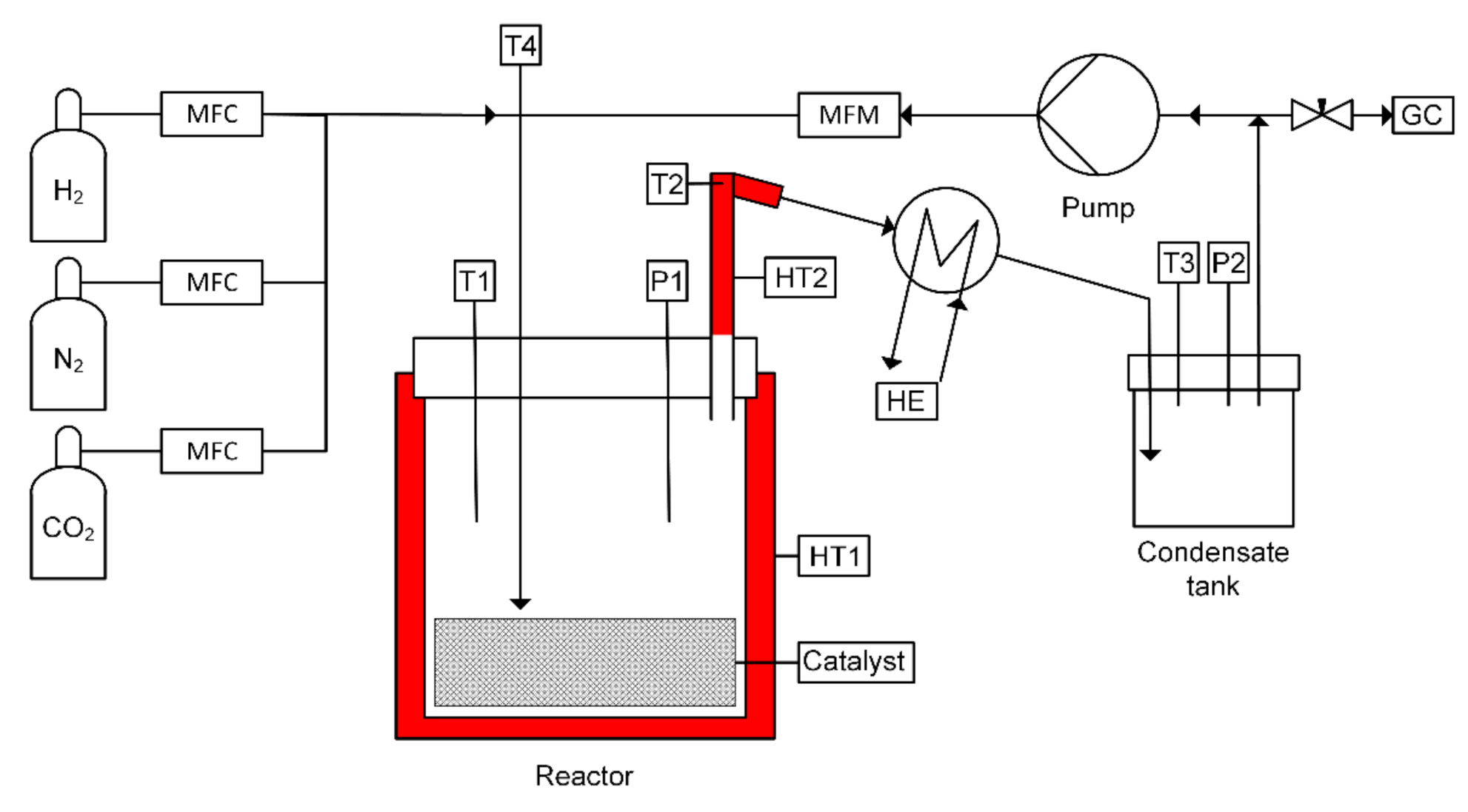
  • Reduction (catalyst activation): To generate the catalytically active Cu0 sites, the calcined CuO/MgO precursor was treated in H2 atmosphere for 3.5 h in the tank reactor that was also used for the hydrogenation experiments (Equation (9)). The activation of the catalyst was performed at the reaction conditions of the CO2 hydrogenation experiments at 573 K and 5 MPa.
    CuO   +   H 2     Cu   +   H 2 O

2.2. Experimental Setup and Procedure

The experimental setup is depicted in Figure 2. It consisted of a semi-continuous tank reactor (BüchiGlasUster “Limbo350”) equipped with an external recycle for the gaseous reactant stream and external condensation of condensable products. The volume of the reactor was 0.450 dm3. Gas recycle was performed by a Ziclón 04 gas circulation pump from Fink. The condensable products methanol and water were condensed in a heat exchanger (HE) at 275 K and collected in a condensate tank (0.1 dm3). The heterogeneous CuO/MgO catalyst precursor was placed in the reactor. The temperature of the reactor (HT1) and the riser to the heat exchanger (HT2) were controlled by an electrical heating system. The reactor was equipped with a wall cooling system. The temperature controller was operated by a process control unit based on LabView. The temperatures of the gas stream were measured by thermo-sensors inside the reactor (T1), before the heat exchanger (T2), inside the condensate tank (T3), and after the gas circulation pump (T4). The pressure was measured inside the reactor (P1) and the condensate tank (P2). The feed gas flow rates were adjusted by mass flow controllers (MFC). The recycle stream flow rate was measured by a mass flow meter (MFM). All temperatures, pressures, and mass flow rates were monitored and recorded. A needle valve was installed between the condensate tank and pump to withdraw gas samples during the experimental run. The samples were analyzed by micro gas chromatography (GC).
8 g of the CuO/MgO catalyst precursor with a particle size distribution of 200–600 µm was placed inside the reactor and activated with H2 to reduce CuO to Cu according to Equation (9). After catalyst activation the reactor was depressurized to atmospheric pressure and kept under H2 atmosphere. To start the hydrogenation experiment, the H2:CO2 feed gas ratio was adjusted to 3:1 (v:v) and the reactor was pressurized to 3 MPa at a constant feed gas flow rate of 600 scm3 min−1. A reference gas sample was taken before the reactor was heated to 573 K. At reaction temperature, the reactor was pressurized to 5 MPa. Then, the gas circulation pump was switched on providing a constant gas flow rate of 10 dm3 h−1 over the whole experimental run. When the respective reaction conditions were reached, the experiment was operated for 48 h. Gas samples were withdrawn by opening the needle valve between the condensate tank and the circulation pump and filled into 20 cm3 vials in three hour-intervals, starting 1.5 h after the experiment had been started. To determine the initial gas-phase composition, a reference sample was taken during the pressurization and heating phase. After having taken gas samples, the reactor was pressurized again to 5 MPa with the initial feed gas ratio of H2:CO2 of 3:1. The time span from pressurization until sampling was specified as an interval (cycle). The last sample was taken after a reaction time of 48 h, followed by depressurization and cooling of the reactor. Before the condensate tank was opened the reactor was purged with N2 with a constant flow rate of 400 scm3 min−1 for 30 min.

2.3. Analysis

Gas samples were analyzed by micro gas chromatography with an Agilent/Inficon microGC 3000 gas chromatograph equipped with two modules (module A and B). Each module consisted of a built-in column and a thermal conductivity detector (TCD). The injection temperature was 363 K in both modules. Module A had a 5 Å molsieve column with an inner diameter of 320 µm, a length of 10 m, and a thickness of 12 µm of the stationary phase. For pre-separation of the gases in backflush mode, a PLOT-U column was installed prior to the molsieve column. The PLOT-U column had an inner diameter of 320 µm, a length of 3 m, and a thickness of 30 µm of the stationary phase. This module was operated in backflush mode with the carrier gas argon. A column temperature of 373 K and pressure of 0.2068 MPa were used. The run-time was 120 s with additional 8 s of backflush time. With this module, H2, N2, CO, and CH4 were detected. Module B had a PLOT-U column with an inner diameter of 320 µm, a length of 8 m, and 30 µm thickness of the stationary phase. It was operated with the carrier gas helium. A column temperature of 333 K and a pressure of 0.1724 MPa were used. The run-time was 120 s. With this module, CO2 (and C2H6, C2H4, and C2H2) was detected.
The methanol concentration in the liquid product was determined by gas chromatography in accordance to the method described in [45]. The Shimadzu GC2010plus was equipped with a flame ionization detector (FID). A Zebron ZB WAXplus column with an inner diameter of 320 µm, a length of 60 m, and a thickness of 0.5 µm was used.
Calculations were based on the ideal gas law to quantify pressure changes by species formation and consumption, and to convert volumes at operation conditions into standard conditions (STP). The total reaction volume was obtained from the volume of the reactor, the volume of the condensate tank, and the volume of the piping. From the total reaction volume at standard conditions (VSTP), the volume fraction in the gas phase (φi) and the molar volume (vi) the molar amount of each component (ni) was calculated (Equation (10)). The relative conversion of CO2 and H2 (Xi) were calculated from the total amount of reactant at the beginning (ni,O) and at the end (ni,t) of an interval, and of the whole experimental run, respectively (Equation (11)). The yield of CO (Yi) was calculated from the total molar amount produced (nCO,t     nCO,0) per mole of CO2 fed to the reactor (nCO2,0) in an interval and for the whole experimental run, respectively (Equation (12)). The total molar amount of methanol produced for each interval (nCH3OH,t) was calculated with a carbon-based mass balance (Equation (13)). The selectivities for methanol and CO (Si) were calculated from the relative conversion of CO2 and the yield, respectively (Equation (14)).
n i = V STP ·   φ i v i
X i = n i , 0 n i , t   n i , 0
Y i = n i , t n i , 0   n CO 2 , 0
n C H 3 O H , t = n CO 2 , 0 + n CO , 0 + n CH 4 , 0 n CO 2 , t n CO , t n CH 4 , t
S i = n i , t n i , 0   n CO 2 , 0 n CO 2 , t = Y i X CO 2

3. Results and Discussion

Figure 3 depicts the reaction temperature and pressure during the experimental run. The experimental run can be split into three phases: (i) heating and pressurization of the reactor to 573 K and 5 MPa, (ii) CO2 hydrogenation over a period of 48 h, and (iii) cooling and depressurization of the reactor. In phase i, the reactor was filled with the reaction mixture in a stoichiometric ratio of H2:CO2 of 3:1 until pressure obtained a value of 3 MPa. After taking the reference sample, the reactor was heated to 573 K and finally pressurized with feed gas to 5 MPa. Phase ii started when the reaction conditions of 573 K and 5 MPa were reached. At that point the circulation pump was switched on and CO2 hydrogenation was performed for 48 h. The temperature was kept constant over the whole experimental run. This reaction phase was characterized by repeated reaction intervals (15 in total). In each interval, the decreasing pressure over time at constant temperature is visible. This is characteristic for a volumetric contractive reaction and the condensation of the condensable products methanol and water. After each interval, a gas sample was taken and analyzed. The reactor was pressurized again to 5 MPa and the next interval started.
According to the caustification conditions (five hours at 723 K followed by two hours at 823 K) the catalyst proved to be active with good selectivity for methanol. This may be dedicated to the caustic nature of MgO that shows high reactivity with respect to CO2 adsorption. The conversion of the reactants H2 and CO2 as well as the formation of the by-product CO from the RWGS reaction can be monitored for each interval and over the total duration of the experiment. In Figure 4 the experimental results of the volume fractions of H2, CO, and CO2 in the gaseous reaction mixture are depicted over the reaction time. In addition to H2, CO, and CO2 negligible amounts of CH4 were detected (below 1.5 vol%). C2H6, C2H4, or C2H2 has not been detected. When starting the experiment only H2 and CO2 were present in the gaseous reaction mixture. Within the first 24 h of the experiment, the amount of CO continuously increased, while the volume fractions of H2 and CO2 decreased. After this start-up phase, the gas-phase composition only denoted slight changes.
Figure 5 shows a cutout of the intervals 9, 10, and 11, exemplarily given for the volume fraction of CO in the gaseous reaction mixture. The points 1, 3, and 5 depict the volume fractions of CO at the end of the intervals 9, 10, and 11, respectively. These data represent measured volume fractions. As mentioned, after each interval and sample taking procedure, the reactor was pressurized again to 5 MPa with the feed gas H2 and CO2 in a stoichiometric ratio of 3:1. The volume fraction of constituents at the beginning of the following interval was different to the volume fraction of constituents measured at the end of the previous interval. The starting volume fractions at the beginning of the intervals 10 and 11 are represented by the points 2 and 4, respectively. The estimated trend in the concentration within one interval is depicted by the dashed line. The dot-dash’ line forming the connection of points 1, 3, and 5 represents the measured gas-phase compositions.
From the gas-phase composition, the relative conversions of H2 and CO2 (Figure 6) and the yield (Figure 7) and selectivity (Figure 8) for methanol and CO can be obtained for each interval. The relative conversion of H2 in the first interval, which lasted 1.5 h, was 8%. In the intervals 2 to 14, the relative conversion of H2 fluctuated between 15% and 21%. As the last interval lasted for four hours to complete the 48 h of the experimental run, the relative conversion of the last interval was the highest with 23%. CO2 conversion confirms the trend of the relative conversion of H2. The lowest relative conversion of CO2 of 22% was determined for the first interval, while the highest relative conversion of 32% was found in the last interval. In the intervals 2 to 14 the relative conversion of CO2 was in the range of 23% to 29%.
The yield of the by-product CO showed a maximum value of 19% in the first interval. It steadily decreased to 4% at the end of the experiment. The yield of methanol had an opposite trend over the reaction time. The lowest value of 3% was obtained in interval 1. The maximum yield of methanol was 28%, recorded in the last interval. Referring to the positive trend of methanol yield it is concluded that the catalyst has still not obtained steady-state activity after 48 h of operation.
The interval selectivities for methanol and CO resemble the yield of both products. In the first two intervals, CO is the preferred hydrogenation product. Within interval 3, this scenario changes towards methanol. The trend continues up to a maximum methanol selectivity of 88% in the last interval.
The bench-scale semi-continuous tank reactor was adapted according to state-of-the-art reactor configurations for industrial methanol synthesis [10]. As opposed to syngas-based industrial methanol synthesis, pure CO2 was used as carbon source in this study. In the repeated cycles of reactant consumption and product condensation followed by reactant re-dosing, an overall relative conversion of CO2 of 76% and a methanol selectivity of 59% were obtained. The calculated results based on the pressure loss during the experiment are consistent with the measured concentration of the liquid product at the end of the experiment with a deviation of ± 2%. This confirms the accuracy of the experimental procedure. Due to continuous product condensation both results are significantly higher than imposed by the thermodynamic equilibrium (XCO2,Eq = 25% and SCH3OH,Eq = 25% at 573 K and 5 MPa; calculated with HSC Chemistry 8 [17]).
Ren et al. [32] investigated the promoting effect of ZnO, ZrO2, and MgO on the activity of Cu/γ-Al2O3 catalyst. The admixture of the metal oxides increased the CuO dispersion, the Cu0 surface area, and decreased the Cu0 particle size. While the promoting effect of ZnO and ZrO2 on CO2 hydrogenation to methanol, when admixed separately, was marginal, simultaneous admixture of both oxides increased CO2 conversion and methanol selectivity significantly. Further improvement was achieved with a Cu/ZnO/ZrO2/MgO/γ-Al2O3 catalyst. The optimal temperature for catalyst activation was found to be the process temperature for CO2 hydrogenation. Though lower activation temperatures resulted in the formation of smaller Cu0 particles and the generation of a higher Cu0 surface area, the catalyst particles seemed to agglomerate when the process temperature exceeded the activation temperature afterwards [32].
Dasireddy et al. [33,34,46] evaluated the effect of alkaline earth metal oxides (MgO, CaO, SrO, and BaO) on a Cu/Al2O3 catalyst for methanol synthesis from CO2 and compared the results with commercially available Cu/ZnO/Al2O3 catalysts. The admixture of alkaline earth metal oxides enhanced the interaction between Al2O3 and CuO, which resulted in a weaker reducibility of CuO. The Cu+:Cu0 ratio and the Cu0 surface area were higher for all alkaline earth metal oxide-containing catalysts compared to the Cu/ZnO/Al2O3 catalyst, and increased in the order of Ba < Ca < Zn < Sr < Mg. High Cu+:Cu0 ratio and high Cu0 surface area were stated as decisive factors for high CO2 conversion. Best results were obtained with Cu/MgO/Al2O3 catalysts, which showed an increased number of active sites for CO2 and H2 adsorption. Preparation conditions at pH = 8 further increased the positive effect of MgO-promoted catalysts. The catalytic performance even exceeded the commercially available benchmark catalyst HFRI20 and LURGI catalysts [33,34,46].
The oxidation state of Cu-species in perovskite-type catalysts (La-Cu-Zn-O) prepared with various promotors was the focus of the study of Zhan et al. [35]. A separate admixture of Ce2O3, MgO, and ZrO2 promoters on perovskite-type catalysts improved the selectivity for methanol compared to the unpromoted catalyst. The highest methanol selectivity was obtained with MgO-promoted catalyst. The higher selectivity was assigned to an increased concentration of caustic sites, higher Cu dispersion, and a special Cuα+ species, which was different to Cu0, Cu+, and Cu2+ [35].
Liu et al. [36] investigated the influence of MgO-promoted Cu/TiO2 catalysts. Admixture of MgO increased the number and strength of caustic sites, but decreased the reducibility of CuO, which was found beneficial for methanol selectivity [36].
Zander et al. [37] compared a Cu/MgO catalyst derived from Cu and Mg (molar ratio of 80:20) nitrate solutions via co-precipitation to a classical malachite-derived Cu/ZnO catalyst. They investigated hydrogenation with various feed gas compositions; pure CO2, CO2/CO mixture and pure CO feed gas stream, at 503 K and 3 MPa. Calcination of the catalyst precursor was carried out in air at 603 K. When pure CO2 and mixed CO2/CO feed gas streams were hydrogenated, the Cu/ZnO catalyst showed a much higher activity than the Cu/MgO catalyst. The Cu/MgO catalyst remained almost inactive in methanol synthesis and catalyzed the reverse water–gas shift reaction instead. The results indicated that the rate of methanol synthesis was not only a function of the exposed Cu surface area. The low activity of Cu/MgO in CO2 hydrogenation was explained by the absence of a strong metal–carrier interaction in the investigated temperature regime.
Nielsen et al. [31] also studied the catalytic effect of Cu/MgO (20 wt%) catalysts in hydrogenation of pure CO2 and pure CO feed gas streams. The catalysts were prepared via precipitation. No information was given about the calcination conditions. Under the applied hydrogenation conditions (523 K and 5 Mpa), Cu/MgO showed high catalytic activity in CO hydrogenation and only little activity in CO2 hydrogenation. In CO2 hydrogenation the relative CO formation rate was five times as high as the relative methanol formation rate. It was concluded that on Cu/MgO, the CO-pathway is much faster, arising from a bifunctional mechanism. They concluded that the facile CO hydrogenation on Cu/MgO proceeds via formate intermediates at the metal/oxide interface. The formate intermediates arise from CO that is inserted into a caustic OH-group from the oxide. This step is followed by Cu-assisted hydrogenation of formate to methanol. In the presence of CO2 carbonates are formed and replace the formate species and thus show an inhibiting effect on methanol synthesis from CO. The catalytic effect of Cu/MgO catalysts on low temperature methanol synthesis from syngas with ethanol as promotor was found to be beneficial by Yang et al. [38].
It is assumed that the mentioned Cu-based catalysts [31,32,33,34,35,36,37,38,39,40] with MgO carrier/promotor were prepared at moderate temperatures providing reactive caustic MgO. It has not been explicitly mentioned in the corresponding papers. Cu/γ -Al2O3 catalysts modified by ZnO, ZrO2 and MgO were prepared via impregnation method and calcined in air at 873 K for six hours [32]. Cu/MgO/Al2O3 catalysts in a molar ratio of Cu:Mg:Al = 50:30:20 were prepared by the co-precipitation method and were calcined in air at 573 K [34] and 873 K [33] for four hours. The promoted perovskite-type catalysts (La-Cu-Zn-O) were prepared by sol-gel method and calcined in air at 673 K for two hours and then at 1073 K for four hours [35]. MgO-promoted Cu/TiO2 catalysts used Mg(NO3) · 6 H2O as magnesium source and were calcined in air at 273 K for four hours [36].
Girod et al. [47] reported in a recent study with steel mill gases and Clariant’s MegaMax®800 (thyssenkrupp Steel Europe site in Duisburg, Germany) catalyst the feasibility of methanol synthesis based on H2-enriched blast furnace gases. However, pronounced catalyst deactivation was observed, highlighting the need for further investigation of trace compounds in the cleaned steel mill gas streams and their possible deactivating effects on the catalyst. Reference tests with various synthetic gas compositions also showed catalyst deactivation within the first 100 h under kinetically controlled reaction conditions. Raising the temperature and thereby changing into thermodynamically controlled reaction conditions resulted in constant methanol equilibrium concentration in the product stream without any indication of catalyst deactivation [47].
Bos et al. [48] investigated the synthesis of methanol by direct CO2 hydrogenation with a commercial Cu/ZnO/Al2O3 catalyst (CP-488) from Johnson Matthey in a semi-continuous reactor with two temperature zones, one for the reaction and the second one for the in situ condensation of the products. CO2 conversion of > 99.5% was reported [48]. From the results of continuous admixture of feed gas and discontinuous removal of product condensate the authors concluded that the carbon-based selectivity loss to CO can be neglected, as—similar to our findings—the CO content remained constant after the starting phase.
Neither internal nor external condensation and recycling has gained satisfactory energy efficiency yet. This offers great potential for further investigation. Based on the semi-continuous reactor concept with in situ condensation a conceptual design for methanol production based on a stand-alone wind power plant, CO2 capture from air, and renewable H2 produced by water electrolysis has been proposed [49]. With an estimated methanol price of 800 EUR t−1, this concept has not yet been made economically feasible, but it is potentially viable enough to encourage further investigations.
To gain progress in the usage of CO2-rich industrial off-gas as feedstock, the design of sophisticated reactor concepts, and the development of easy to prepare and recycle catalysts with sufficient catalytic activity will play an important role in the mitigation of industrial CO2 emissions. The comparison of literature data with the performance of the Cu/MgO catalyst prepared by our group encourages investigation of separate caustification/sintering of the MgO precursor before mixing with the catalytically active constituent(s).

4. Conclusions

Methanol synthesis from CO2 with a Cu/MgO catalyst was investigated. The topic has been investigated in an ongoing project to collect data about the interaction of sintering temperature dependent MgO reactivity and the catalytic activity of Cu/MgO catalysts. In a first experimental series of catalyst preparation the caustification temperature of the MgO carrier material was limited to a level of 823 K to obtain highly active MgO with respect to CO2 adsorption capacity. Then, the MgO carrier was impregnated with copper nitrate, calcined and activated, and then tested in a semi-continuous bench scale tank reactor setup. The results of this first series of experiments confirm the catalytic activity of the catalyst as prepared. The results indicate that the activity of the catalyst, as prepared, still becomes better after 48 h of operation. From the results of this study, it is concluded that in methanol synthesis Cu/MgO catalysts with high caustic reactivity of MgO provide sufficient activity. The results of this study offer a profound basis for further investigation of MgO-based catalysts with different caustic reactivity. To gain results about the role of the carrier material MgO the effect of different caustification/sintering temperature levels on the activity has to be investigated in next steps. However, these investigations will need an improved determination of the caustic reactivity of MgO and complete chemical and morphological analysis of the catalyst to identify the effect of MgO quality on the catalytic activity of Cu/MgO catalysts.

Author Contributions

Conceptualization, S.K. and S.L.; methodology, S.K., S.L. and M.S.; software, S.K.; validation, S.K. and S.L.; formal analysis, S.K.; investigation, S.K. and M.P.; data curation, S.K.; writing—original draft preparation, S.K.; writing—review and editing, S.K., S.L. and M.S.; visualization, S.K.; supervision, S.L.; project administration, S.K. and S.L. All authors have read and agreed to the published version of the manuscript.

Funding

This research received no external funding.

Institutional Review Board Statement

Not applicable.

Informed Consent Statement

Not applicable.

Acknowledgments

The authors gratefully acknowledge the support from the NAWI Graz program. Thanks are also due to Tanja Weiß, Mario Kircher, and Christian Winter for their support with laboratory work. Open Access Funding by the Graz University of Technology.

Conflicts of Interest

The authors declare no conflict of interest.

References

  1. Friedlingstein, P.; Jones, M.W.; O’Sullivan, M.; Andrew, R.M.; Hauck, J.; Peters, G.P.; Peters, W.; Pongratz, J.; Sitch, S.; le Quéré, C.; et al. Global Carbon Budget 2019. Earth Syst. Sci. Data 2019, 11, 1783–1838. [Google Scholar] [CrossRef] [Green Version]
  2. Jiang, X.; Nie, X.; Guo, X.; Song, C.; Chen, J.G. Recent Advances in Carbon Dioxide Hydrogenation to Methanol via Heterogeneous Catalysis. Chem. Rev. 2020, 120, 7984–8034. [Google Scholar] [CrossRef]
  3. Jadhav, S.G.; Vaidya, P.D.; Bhanage, B.M.; Joshi, J.B. Catalytic carbon dioxide hydrogenation to methanol: A review of recent studies. Chem. Eng. Res. Des. 2014, 92, 2557–2567. [Google Scholar] [CrossRef]
  4. Din, I.U.; Shaharun, M.S.; Alotaibi, M.A.; Alharthi, A.I.; Naeem, A. Recent developments on heterogeneous catalytic CO2 reduction to methanol. J. CO2 Util. 2019, 34, 20–33. [Google Scholar] [CrossRef]
  5. Dang, S.; Yang, H.; Gao, P.; Wang, H.; Li, X.; Wei, W.; Sun, Y. A review of research progress on heterogeneous catalysts for methanol synthesis from carbon dioxide hydrogenation. Catal. Today 2019, 330, 61–75. [Google Scholar] [CrossRef]
  6. Olah, G.A. Beyond Oil and Gas: The Methanol Economy. Angew. Chem. Int. Ed. 2005, 44, 2636–2639. [Google Scholar] [CrossRef] [PubMed]
  7. Yang, H.; Zhang, C.; Gao, P.; Wang, H.; Li, X.; Zhong, L.; Wei, W.; Sun, Y. A review of the catalytic hydrogenation of carbon dioxide into value-added hydrocarbons. Catal. Sci. Technol. 2017, 7, 4580–4598. [Google Scholar] [CrossRef]
  8. Álvarez, A.; Bansode, A.; Urakawa, A.; Bavykina, A.V.; Wezendonk, T.A.; Makkee, M.; Gascon, J.; Kapteijn, F. Challenges in the Greener Production of Formates/Formic Acid, Methanol, and DME by Heterogeneously Catalyzed CO2 Hydrogenation Processes. Chem. Rev. 2017, 117, 9804–9838. [Google Scholar] [CrossRef]
  9. Zhao, Y.-F.; Yang, Y.; Mims, C.; Peden, C.H.; Li, J.; Mei, D. Insight into methanol synthesis from CO2 hydrogenation on Cu(111): Complex reaction network and the effects of H2O. J. Catal. 2011, 281, 199–211. [Google Scholar] [CrossRef]
  10. Deutschmann, O.; Knözinger, H.; Kochloefl, K.; Turek, T. Heterogeneous Catalysis and Solid Catalysts, 3. Industrial Applications. In Ullmann’s Encyclopedia of Industrial Chemistry; Wiley: Chichester, UK, 2010. [Google Scholar]
  11. Gurau, B.; Smotkin, E.S. Methanol crossover in direct methanol fuel cells: A link between power and energy density. J. Power Sources 2002, 112, 339–352. [Google Scholar] [CrossRef]
  12. Breeze, P.A. Power Generation Technologies, 3rd ed.; Newnes: Kidlington, UK; Oxford, UK, 2019. [Google Scholar]
  13. Day, W.H. Methanol Fuel in Commercial Operation on Land and Sea. Gas Turbine World. 2016. Available online: https://www.methanol.org/wp-content/uploads/2016/12/Methanol-Nov-Dec-2016-GTW-.pdf (accessed on 7 June 2021).
  14. Bertau, M.; Offermanns, H.; Plass, L.; Schmidt, F.; Wernicke, H.-J. Methanol: The Basic Chemical and Energy Feedstock of the Future; Springer: Berlin/Heidelberg, Germany, 2014. [Google Scholar]
  15. Ma, J.; Sun, N.; Zhang, X.; Zhao, N.; Xiao, F.; Wei, W.; Sun, Y. A short review of catalysis for CO2 conversion. Catal. Today 2009, 148, 221–231. [Google Scholar] [CrossRef]
  16. Ott, J.; Gronemann, V.; Pontzen, F.; Fiedler, E.; Grossmann, G.; Kersebohm, D.B.; Weiss, G.; Witte, C. Methanol. In Ullmann’s Encyclopedia of Industrial Chemistry; Wiley: Chichester, UK, 2010; pp. 1–27. [Google Scholar]
  17. Outotec Technologies. HSC Chemistry® Software; Outotec Technologies: Helsinki, Finland, 2018. [Google Scholar]
  18. Raudaskoski, R.; Turpeinen, E.; Lenkkeri, R.; Pongrácz, E.; Keiski, R.L. Catalytic activation of CO2: Use of secondary CO2 for the production of synthesis gas and for methanol synthesis over copper-based zirconia-containing catalysts. Catal. Today 2009, 144, 318–323. [Google Scholar] [CrossRef]
  19. Arena, F.; Mezzatesta, G.; Zafarana, G.; Trunfio, G.; Frusteri, F.; Spandaro, L. How oxide carriers control the catalytic functionality of the Cu-ZnO system in the hydrogenation of CO2 to methanol. Catal. Today 2013, 210, 39–46. [Google Scholar] [CrossRef]
  20. Qi, G.-X.; Zheng, X.-M.; Fei, J.-H.; Hou, Z.-Y. Low-temperature methanol synthesis catalyzed over Cu/γ-Al2O3-TiO2 for CO2 hydrogenation. Catal. Lett. 2001, 72, 191–196. [Google Scholar] [CrossRef]
  21. Chinchen, G.C.; Denny, P.J.; Parker, D.G.; Spencer, M.S.; Whan, D.A. Mechanism of methanol synthesis from CO2/CO/H2 mixtures over copper/zinc oxide/alumina catalysts: Use of 14C-labelled reactants. Appl. Catal. 1987, 30, 333–338. [Google Scholar] [CrossRef]
  22. Bowker, M. The mechanism of methanol synthesis on copper/zinc oxide/alumina catalysts. J. Catal. 1988, 109, 263–273. [Google Scholar] [CrossRef]
  23. Portha, J.-F.; Parkhomenko, K.; Kobl, K.; Roger, A.-C.; Arab, S.; Commenge, J.-M.; Falk, L. Kinetics of Methanol Synthesis from Carbon Dioxide Hydrogenation over Copper-Zinc Oxide Catalysts. Ind. Eng. Chem. Res. 2017, 56, 13133–13145. [Google Scholar] [CrossRef]
  24. Aresta, M.; Dibenedetto, A. Utilisation of CO2 as a chemical feedstock: Opportunities and challenges. Dalton Trans. 2007, 2975–2992. [Google Scholar] [CrossRef] [PubMed]
  25. Razali, N.A.M.; Lee, K.T.; Bhatia, S.; Mohamed, A.R. Heterogeneous catalysts for production of chemicals using carbon dioxide as raw material: A review. Renew. Sustain. Energy Rev. 2012, 16, 4951–4964. [Google Scholar] [CrossRef]
  26. Agny, R.M.; Takoudis, C.G. Synthesis of methanol from carbon monoxide and hydrogen over a copper-zinc oxide-alumina catalyst. Ind. Eng. Chem. Prod. Res. Dev. 1985, 24, 50–55. [Google Scholar] [CrossRef]
  27. Henrici-Olivé, G.; Olivé, S. Mechanistic reflections on the methanol synthesis with Cu/Zn catalysts. J. Mol. Catal. 1982, 17, 89–92. [Google Scholar] [CrossRef]
  28. Fujitani, T.; Saito, M.; Kanai, Y.; Kakumoto, T.; Watanabe, T.; Nakamura, J.; Uchijima, T. The role of metal oxides in promoting a copper catalyst for methanol synthesis. Catal. Lett. 1994, 25, 271–276. [Google Scholar] [CrossRef]
  29. Robbins, J.L.; Iglesia, E.; Kelkar, C.P.; DeRites, B. Methanol synthesis over Cu/SiO2 catalysts. Catal. Lett. 1991, 10, 1–10. [Google Scholar] [CrossRef]
  30. Baltes, C.; Vukojevic, S.; Schuth, F. Correlations between synthesis, precursor, and catalyst structure and activity of a large set of CuO/ZnO/Al2O3 catalysts for methanol synthesis. J. Catal. 2008, 258, 334–344. [Google Scholar] [CrossRef]
  31. Nielsen, N.D.; Thrane, J.; Jensen, A.D.; Christensen, J.M. Bifunctional Synergy in CO Hydrogenation to Methanol with Supported Cu. Catal. Lett. 2020, 150, 1427–1433. [Google Scholar] [CrossRef]
  32. Ren, H.; Xu, C.-H.; Zhao, H.-Y.; Wang, Y.-X.; Liu, J.; Liu, J.-Y. Methanol synthesis from CO2 hydrogenation over Cu/γ-Al2O3 catalysts modified by ZnO, ZrO2 and MgO. J. Ind. Eng. Chem. 2015, 28, 261–267. [Google Scholar] [CrossRef]
  33. Dasireddy, V.D.; Neja, S.Š.; Likozar, B. Correlation between synthesis pH, structure and Cu/MgO/Al2O3 eterogeneous catalyst activity and selectivity in CO2 hydrogenation to methanol. J. CO2 Util. 2018, 28, 189–199. [Google Scholar] [CrossRef]
  34. Dasireddy, V.D.; Štefančič, N.S.; Huš, M.; Likozar, B. Effect of alkaline earth metal oxide (MO) Cu/MO/Al2O3 catalysts on methanol synthesis activity and selectivity via CO2 reduction. Fuel 2018, 233, 103–112. [Google Scholar] [CrossRef]
  35. Zhan, H.; Li, F.; Gao, P.; Zhao, N.; Xiao, F.; Wei, W.; Zhong, L.; Sun, Y. Methanol synthesis from CO2 hydrogenation over La–M–Cu–Zn–O (M = Y, Ce, Mg, Zr) catalysts derived from perovskite-type precursors. J. Power Sources 2014, 251, 113–121. [Google Scholar] [CrossRef]
  36. Liu, C.; Guo, X.; Guo, Q.; Mao, D.; Yu, J.; Lu, G. Methanol synthesis from CO2 hydrogenation over copper catalysts supported on MgO-modified TiO2. J. Mol. Catal. A Chem. 2016, 425, 86–93. [Google Scholar] [CrossRef]
  37. Zander, S.; Kunkes, E.L.; Schuster, M.E.; Schumann, J.; Weinberg, G.; Teschner, D.; Jacobsen, N.; Schlögl, R.; Behrens, M. The role of the oxide component in the development of copper composite catalysts for methanol synthesis. Angew. Chem. Int. Ed. 2013, 52, 6536–6540. [Google Scholar] [CrossRef]
  38. Yang, R.; Zhang, Y.; Iwama, Y.; Tsubaki, N. Mechanistic study of a new low-temperature methanol synthesis on Cu/MgO catalysts. Appl. Catal. A Gen. 2005, 288, 126–133. [Google Scholar] [CrossRef]
  39. Kim, H.Y.; Lee, H.M.; Park, J.-N. Bifunctional Mechanism of CO2 Methanation on Pd-MgO/SiO2 Catalyst: Independent Roles of MgO and Pd on CO2 Methanation. J. Phys. Chem. C 2010, 114, 7128–7131. [Google Scholar] [CrossRef]
  40. Loder, A.; Siebenhofer, M.; Lux, S. The reaction kinetics of CO2 methanation on a bifunctional Ni/MgO catalyst. J. Ind. Eng. Chem. 2020, 85, 196–207. [Google Scholar] [CrossRef]
  41. Seeger, M.; Otto, W.; Flick, W.; Bickelhaupt, F.; Akkerman, O.S. Magnesium Compounds. In Ullmann’s Encyclopedia of Industrial Chemistry; Wiley: Chichester, UK, 2010. [Google Scholar]
  42. Jin, F.; Al-Tabbaa, A. Thermogravimetric study on the hydration of reactive magnesia and silica mixture at room temperature. Thermochim. Acta 2013, 566, 162–168. [Google Scholar] [CrossRef]
  43. Yang, N.; Ning, P.; Li, K.; Wang, J. MgO-based adsorbent achieved from magnesite for CO2 capture in simulate wet flue gas. J. Taiwan Inst. Chem. Eng. 2018, 86, 73–80. [Google Scholar] [CrossRef]
  44. Salomão, R.; Pandolfelli, V.C. Magnesia sinter hydration–dehydration behavior in refractory castables. Ceram. Int. 2008, 34, 1829–1834. [Google Scholar] [CrossRef]
  45. Toth, A.; Schnedl, S.; Painer, D.; Siebenhofer, M.; Lux, S. Interfacial Catalysis in Biphasic Carboxylic Acid Esterification with a Nickel-Based Metallosurfactant. ACS Sustain. Chem. Eng. 2019, 7, 18547–18553. [Google Scholar] [CrossRef]
  46. Dasireddy, V.D.; Likozar, B. The role of copper oxidation state in Cu/ZnO/Al2O3 catalysts in CO2 hydrogenation and methanol productivity. Renew. Energy 2019, 140, 452–460. [Google Scholar] [CrossRef]
  47. Girod, K.; Lohmann, H.; Kaluza, S. Methanol Synthesis with Steel Mill Gases: Performance Investigations in an On-Site Technical Center. Chem. Ing. Tech. 2021, 93, 850–855. [Google Scholar] [CrossRef]
  48. Bos, M.J.; Brilman, D. A novel condensation reactor for efficient CO2 to methanol conversion for storage of renewable electric energy. Chem. Eng. J. 2015, 278, 527–532. [Google Scholar] [CrossRef] [Green Version]
  49. Bos, M.J.; Kersten, S.; Brilman, D. Wind power to methanol: Renewable methanol production using electricity, electrolysis of water and CO2 air capture. Appl. Energy 2020, 264, 114672. [Google Scholar] [CrossRef]
Figure 1. (a) Standard Gibbs free energies of reaction (ΔGR0) for carbon dioxide (CO2) hydrogenation to methanol and methane, reverse water gas shift reaction (RWGS), and carbon monoxide (CO) hydrogenation to methanol; (b) Enthalpies of reaction (ΔHR) for CO2 hydrogenation to methanol and methane, RWGS, and CO hydrogenation to methanol; data calculated with HSC Chemistry 8 [17].
Energies 14 04319 g001
Figure 2. Experimental setup of the semi-continuous tank reactor with external recycle for the gaseous reactant stream and external condensation of condensable products in bench scale.
Energies 14 04319 g002
Figure 3. Reaction temperature and pressure during one experimental run, consisting of initial heating and pressurization of the reactor (phase i from 0 to 3 h), 48 h reaction phase characterized by repeated decrease of pressure due to reactant consumption and product condensation and re-pressurization (phase ii from 3 h to 51 h) followed by cooling and depressurization in phase iii.
Energies 14 04319 g003
Figure 4. Volume fraction (φi) of the gaseous reaction mixture for CO2 hydrogenation to methanol over the Cu/MgO (38 wt%) catalyst in the semi-continuous tank reactor with external recycle and condensation; operation conditions: 573 K and 5 MPa.
Energies 14 04319 g004
Figure 5. Cutout of the trend of the gas-phase volume fraction of CO for the intervals 9, 10, and 11. The points 1, 3, and 5 show the measured volume fraction at the end of the intervals 9, 10, and 11, respectively. The points 2 and 4 represent the calculated volume fraction at the beginning of interval 10 and 11, respectively. The estimated trend of the volume fraction within one interval is depicted by the dashed line. The ‘dot-dash’ line forming the connection of points 1, 3, and 5 represents the measured gas-phase volume fraction of CO.
Energies 14 04319 g005
Figure 6. Relative conversion of H2 and CO2 for the different intervals during the experimental run.
Energies 14 04319 g006
Figure 7. Interval yields of CO and methanol during the experimental run.
Energies 14 04319 g007
Figure 8. Interval selectivities of CO and methanol during the experimental run.
Energies 14 04319 g008
Publisher’s Note: MDPI stays neutral with regard to jurisdictional claims in published maps and institutional affiliations.

