Article

Catalytic Hydroisomerisation of Fischer–Tropsch Waxes to Lubricating Oil and Investigation of the Correlation between Its Physical Properties and the Chemical Composition of the Corresponding Fuel Fractions

Karlsruhe Institute of Technology, 76131 Karlsruhe, Germany
*
Author to whom correspondence should be addressed.
Energies 2021, 14(14), 4202; https://doi.org/10.3390/en14144202
Submission received: 4 June 2021 / Revised: 8 July 2021 / Accepted: 9 July 2021 / Published: 12 July 2021
(This article belongs to the Special Issue Catalytic Processes for CO2 Utilization)

Abstract

:
Due to environmental concerns, the role of renewable sources for petroleum-based products has become an invaluable research topic. One possibility of achieving this goal is the Fischer–Tropsch synthesis (FTS) based on sustainable raw materials. Those materials include, but are not limited to, synthesis gas from biomass gasification or hydrogen through electrolysis powered by renewable electricity. In recent years, the utilisation of CO2 as carbon source for FTS was one main R&D topic. This is one of the reasons for its increase in value and the removal of its label as being just exhaust gas. With the heavy product fraction of FTS, referred to as Fischer–Tropsch waxes (FTW), being rather limited in their application, catalytic upgrading can help to increase the economic viability of such a process by converting the waxes to high value transportation fuels and lubricating oils. In this paper, the dewaxing of FTW via hydroisomerisation and hydrocracking was investigated. A three phase fixed bed reactor was used in combination with a zeolitic catalyst with an AEL (SAPO-11) structure and 0.3 wt% platinum (Pt). The desired products were high quality white oils with low cloud points. These products were successfully produced in a one-step catalytic dewaxing process. Within this work, a direct correlation between the physical properties of the white oils and the chemical composition of the simultaneously produced fuel fractions could be established.

1. Introduction

Environmental trepidations are an excessively discussed topic and the demand for fossil free energy supply is increasing. Current legislative measures, such as the taxation of carbon dioxide (CO2) as proposed in Germany will inevitably push prices of fossil fuels and carbon sources to novel highs [1,2]. The most common suggestions are the increased usage of electric power in sectors such as transportation and commutation. While an energy supply via battery is viable for cars and light commercial vehicles, it reaches its limits with air and sea travel due to the low energy density of batteries [3]. This problem has reignited the demand for renewable liquid energy carriers, such as middle distillates from Fischer–Tropsch (FT) synthesis. Baseline for this approach is the usage of carbon monoxide (CO) and hydrogen (H2) as synthesis gas. The original feedstock for FT synthesis, which is coal, can be replaced by renewable sources such as bio mass [4]. Another possibility is the usage or reuse of excess CO2 as carbon source, which has been proven a viable and flexible alternative for CO [5]. Research has also been conducted regarding the use of the FT synthesis in a power-to-liquid (PTL) approach [6]. A general description of the FT synthesis from CO2 to paraffins can be defined as the following.
CO2 + H2 → CO + H2O
n CO + (2n + 1) H2 → CnH2n+2 + n H2O
The main issue with this process is that it will, with certain exceptions [7,8], almost always result in a probability distribution of products according to Schulz–Flory, reaching from methane to heavy paraffinic waxes [9]. The product distribution can be regulated using higher or lower reaction temperatures with lighter products (based on molecular weight) at higher temperatures and heavier products at lower ones [10]. Those processes are known as high temperature FT synthesis (HTFT) and low temperature FT synthesis (LTFT) [11]. The second issue is the paraffinic nature of FT products. Them being free of poly aromatic hydrocarbons (PAH) will generally result in lower emissions and soot formation during combustion [12]. However, the high amount of n-paraffins hinders the application of FT products as fuel due to poor cold flow properties or low octane numbers. A similar issue refers to the wax fraction. With its high melting point, its product applications are rather limited. Examples include industrial coatings and usage in street construction. By lowering the melting point, especially regarding the lubricant sector, more applications can be developed. Those problems can be resolved with a hydroprocessing step. The demand for synthetic lubricants increased as well in recent years due to changing quality demands. Miller et al. reported a shift to lower viscosity oils in order to decrease friction in mechanical stressed areas and lower oil volatility to increase longevity and sustainability [13]. Multiple authors have extensively studied hydroprocessing or hydroconversion of FT products to middle distillates [14,15,16,17,18,19], making the production of liquid transportation fuels from FT waxes a well-established process. The same cannot be stated about the production of lubricants from FT-waxes. The process itself is established and commercially used, for example, at the Shell PEARL GTL plant in Qatar, which utilizes offshore gas to produce FT products and subsequently lubricants such as technical and medicinal grade white oil [20]. The know-how is, with some mentionable exceptions [21,22,23], rather limited to patent literature [24,25,26,27]. Therefore, the aim of this paper is to investigate and describe the lubricant production from FT waxes and the differences of yield, viscosity and cloud point depending on reaction temperature and pressure. A correlation between molecular composition of the simultaneously produced fuel fractions to the corresponding lube properties is also to be established.

2. Theoretical Background

2.1. Dewaxing

The process of dewaxing describes the removal of n-paraffins from a given hydrocarbon mixture with the purpose of lowering the melting point. There a two main, commercially used dewaxing processes. Solvent dewaxing and catalytic dewaxing. Solvent dewaxing is based on removing wax crystals through precipitation. The untreated oil is usually diluted with an organic solvent such as ketones or aromatics or a mixture of both. It is then cooled below the desired pour point under constant stirring. This results in the formation of wax crystals, which can subsequently be removed by mechanical separation, such as cold filtration [28]. The main advantage of this process is its high yield and high viscosity index during dewaxing of petroleum based feedstock, yet it does require high amounts of extra solvent and additional distillation. Catalytic dewaxing is the selective removal of normal paraffins through cracking or isomerisation. While commercial base stock, such as vacuum gas oil, can be dewaxed by cracking of the long chain paraffins and removal of the lighter fraction via distillation, this is not true for FT-waxes. Those consist almost exclusively of straight chain hydrocarbons. Consequently, cracking would consume the entire wax, transforming it into lighter fuels. To dewax this product, hydroisomerisation is necessary. This will convert the normal paraffins into branched ones by reducing their pour point significantly while mostly maintaining their boiling range [29]. Hsu and Robinson also reported that commercial dewaxing through isomerisation has been available since 1993 when Chevron developed its ISODEWAXING® process using SAPO catalysts. Similar techniques for hydroisomerisation are employed at the Shell PEARL GTL plant.

2.2. Hydroprocessing

Hydroprocessing is an umbrella term for multiple reactions of hydrocarbons under the H2 atmosphere, including hydrotreating, hydrofinishing, hydrocracking and hydro-isomerisation. In this paper, hydroprocessing refers to the latter two. Numerous different mechanisms of hydroisomerisation and hydrocracking were described by Bouchy et al. [15]. An example can be seen in Figure 1. The formation of a new isomer is depicted at (a), while the cracking reaction can be observed at (b). Both require the presence of carbenium ions. The reaction rate of isomerisation is generally higher than the one for cracking, with the notable exception at the scisscion of tertiary carbon ions which can exceed the isomerisation rate.
Cracking of FT products shifts the yield distribution away from waxy components to the desired yields, usually towards the middle distillate range. Isomerisation will lower the melting points in contrast to their n-paraffin counterparts [30], which will result in better cold flow properties.

2.3. Catalytic Mechanism

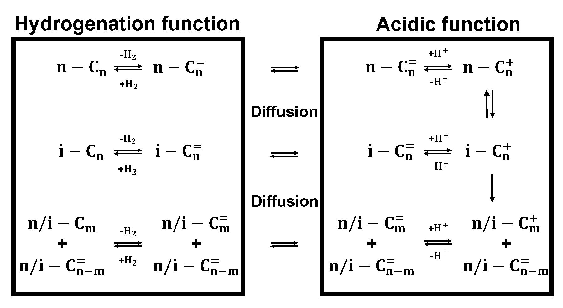
Hydroprocessing itself is conducted on a bifunctional catalyst, which means there are two different active centres on the catalyst surface, with distinct applications: A metallic site for hydrogenation and dehydrogenation of the product, as well as an acidic site for isomerisation and cracking [15]. The acid component can be provided by a zeolite carrier, which can have varying degrees of acidity. A detailed description of the individual mechanisms is depicted in Figure 2.
The saturated n-paraffin is dehydrated on the metallic site and an olefin is formed. The olefin transitions to the acidic site of the catalyst via diffusion. Due to proton uptake on the acidic catalyst site, secondary carbenium ions are formed and those can either crack or branch out to form tertiary carbenium ions [31]. Disintegration of the carbenium ions will result in rehydrogenation and formation of saturated n-paraffins and iso-paraffins.

2.4. Synthetic Lubricants from FT Waxes

Lubricating oils can be described as hydrophobic liquids, which have boiling points higher than water and do not crystalize at room temperature. Commercial Lubricants are specified more clearly. They depend on different parameters including the type of their feedstock (Table 1), their density, viscosity, viscosity index, pour point, cloud point, boiling range, volatility, flash point, amount of saturates, naphtenes and aromatics, oxidative resistance, acidity, colour and conradson carbon residue (CCR). A synthetic lubricant from a GTL process is categorised as API III+ [29].
Wax from FT synthesis is a decent feedstock for lubricant production due to its low content of heteroatoms or other impurities. The main issue with FTW is that its melting point is usually above 40 °C. The reason is the high amount of linear paraffins in the mixture. In order to reduce the melting temperature of the wax, the chemical composition has to be altered by hydroisomerisation as explained above. FTW dewaxing has been performed using catalytic dewaxing under hydrogen in either a one-step or two-step approach, occasionally including solvent dewaxing as a final step [22,23,24,25,26,27]. A pretreatment step may necessarily not required. This was stated by Miller et al. [13] who hydroisomerised FT waxes mixed with pyroysed plastics to produce lubricating oils. This results in the conclusion that hydrogenation of pure FT wax prior to hydroisomerisation should be unnecessary. Before hydroprocessing certain wax fractions, what needs to be clarified is whether residual oxygenates can hurt the used catalyst. The two main properties that any lubricating oil will be defined by are its viscosity and its congealing point. The viscosity of hydrocarbon oils is mainly dependent on its average chain length and can only be slightly adjusted by its chemical structure. The kinematic viscosity can even be used to calculate the median molecular weight of the lubricant [32]. The congealing temperature is heavily dependent on the molecular structure, with n-paraffins having the highest melting points in a given carbon range [29].

2.5. Cloud Point

The cloud point (CP) of a paraffin mixture defines the temperature when precipitation of wax crystals begins. It is usually at higher temperatures than other cold flow properties [33]. At CP-temperature, the fluidity of the mixture is not yet inhibited, but wax crystals start to form, which can accumulate on cold surfaces and subsequently plug filters [34]. It is slightly above the common cold filter plugging point (CFPP). Due to it being the highest temperature where significant effects on the consistency of the lubricant can be observed, this work has chosen to display the change in cold flow behaviour.

3. Materials and Methods

3.1. Reactor Setup and Materials Used

In order to apply the processes proposed in the previous section, a three-phase fixed bed reactor was used (Figure 3). The melted wax was kept in a five litre storage vessel from where it was pumped at 90 °C into the reactor by using a high pressure and high temperature piston pump (Bischoff HPD Pump Multitherm 200 model 3351).
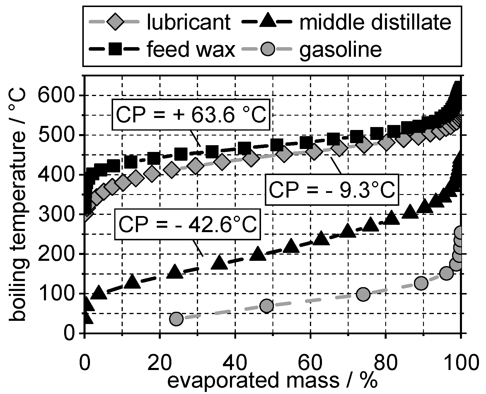
This allows a liquid flowrate in the range from 0.6–300 mL/h. The reactor itself consists of a tube with 14.9 mm inner diameter and a length of 800 mm. The used reaction zone itself consists of 400 mm. A 1/8’’ tube is inserted in the middle to provide access for temperature measurements. After the reaction zone, the product mixture enters three consecutive vapour–liquid separation vessels with a volume of 800 mL each and from there it can be removed via a needle valve at the bottom. In the reaction zone, 20 g (100–200 µm) of a commercially available zeolitic catalyst with AEL (SAPO-11) structure and 0.3 wt% platinum as a hydrogenation agent were used. This catalyst was chosen with respect to its high selectivity towards isomerisation [35]. The reaction temperature was set on the outside of the reactor tube. Under reaction conditions, the inner temperature increases approximately between 1–2 °C. The feed was Fischer–Tropsch wax from Sasol with a cloud point, as determined by differential scanning calorimetry (DSC) measurement, of 63.6 °C (Figure 4). All experiments were conducted at the same wax flow rate of 0.28 mL/min at 90 °C, resulting in a liquid hourly space velocity (LHSV) of 0.75 h−1. The hydrogen flow of 550 mL/min (at laboratory conditions) was also not changed.

3.2. Sample Preparation

The retrieved samples were weighed and separated according to the following atmospheric boiling ranges: gasoline <170 °C, middle distillate 170–340 °C and lubricant >340 °C. In order to avoid overheating the samples, separation of middle distillate from the lubricant was conducted under vacuum using a standard laboratory glass distillation apparatus. The required vacuum was generated with a water-jet pump. The remaining wax crystals were removed by centrifugation (Hettich Rotana 460) at 9000 rpm for 10 min.

3.3. Analytics

The cloud points (CP) of lubricant fractions and middle distillate were determined with differential scanning calorimetry (Netzsch DSC 214 Polyma) under nitrogen atmosphere. In order to achieve exact measurements, a constant cooling rate and sample weight is necessary [36]. For one analysis, 10 mg of the sample was used and a cooling rate of 10 K/min was applied. Afterwards, the sample was reheated before being removed. The cloud point was identified by extrapolating the tangents of the first detectable peak-onset during cooling. The measured temperature at the intersections of both straight lines was noted (TM). An exemplary peak onset for a commercial paraffin oil and the used temperature programme can be observed in Figure 5. This sequence was developed based on the methods already presented in the literature [37,38] or slightly adapted from similar ASTM Norms [39,40]. The DSC-device required additional calibration to determine the start of crystallisation during cooling. For this purpose, pure components with various solidification temperatures were chosen (n-dodecane, mesitylene, deuterated chloroform, butanone, tetradecane, octacosane, tetracosane, hexadecane and triacontane). Aditionally two Cloud Point reference diesel fuels (ASTM D 2500 [41]) with CPs at 7.7 ± 0.6 °C and −21.0 ± 2 °C were included. The calibration showed significant deviancy of the crystallisation temperature (TC) and the measured temperature (TM), the correctional functions can be reviewed in Appendix A, Appendix B and Appendix C. The initial calibration did not include the reference fuels. A sample of 10 mg each were analysed. The resulting temperatures were 8.29 °C and −19.09 °C which lies within the stated deviation as determined by ASTM D 2500 and also within the expected scope of DSC measurements, described by Claudy et al. [42]. In order to improve accuracy, the samples were included into the calibration, as presented in Appendix A. It needs to be stated that it was not always possible to determine a clear peak with this method. Some samples crystallized homogenously with no detectable CP. Those were not considered in this work.
The dynamic viscosity was measured with a plate rheometer (Anton Paar MCR 302e) at a sheer rate of 50 s−1 and a rotating plate size of 50 mm for five minutes to achieve reliable measurements. The required density to calculate the kinematic viscosity was determined by oscillating tube measurement (Anton Paar DMA 4200). The composition of the gasoline fractions was analysed using a PAC Reformulyzer M4 Hydrocarbon Group Type Analysis. This allowed the measurement of n-/iso-Paraffin content and also detected possible aromatic or naphthenic components. The composition of the produced gas phase was determined by gas chromatography (Agilent Technologies 7890A). Due to calibration problems, the gas phase could only be analysed for one set of parameters (Appendix B) and will not be further discussed in this paper. Determination of the boiling ranges was conducted using a simulated distillation method (Shimadzu Nexis GC-2030).

4. Results

4.1. Boiling Range and Cloud Points

In order to check if the distillation was successful, the boiling range and cloud points of the produced oil had to be measured. This was performed via simulated distillation and an example is given in Figure 6. The individual data points refer to the sum of iso- and n-paraffins within a given carbon number. It was performed in this manner to incorporate response factors. It can be observed that the resulting oil fraction boils entirely above 300 °C and has less than 10 wt% boiling below 340 °C. While the boiling range of the lubricant barely changes, the cloud point could be reduced by 73 °C. With the cloud point being below room temperature and the boiling range indicating no fuel components within the mixture, a lubricating oil was successfully produced. The variation in cloud points was investigated with regards to changing process parameters, in this case the points were reactor temperature and pressure.
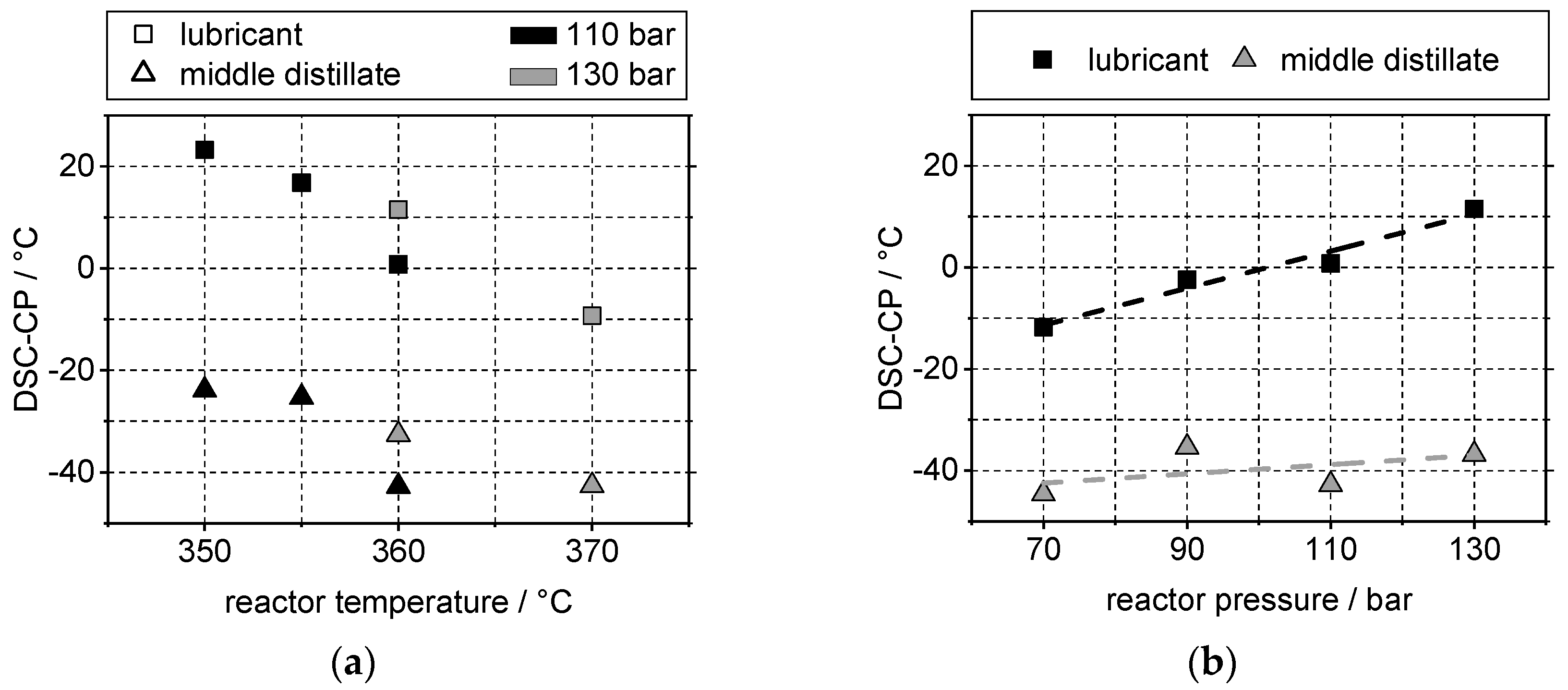
It can be observed that the cloud point decreases rapidly with increasing temperature (Figure 7a). This indicates higher n-paraffin conversion and higher yield of isomers at higher temperatures as expected. Higher pressure results in higher cloud point (Figure 7b). This correlates with the mechanism of hydrocracking, where higher temperature increases carbenium ion formation, while higher pressure inhibits it. The amount of isoparaffins should therefore be higher at low cloud points. A direct measurement of n-paraffins in the oil fraction was not possible with the available setup.

4.2. Yield and Viscosity

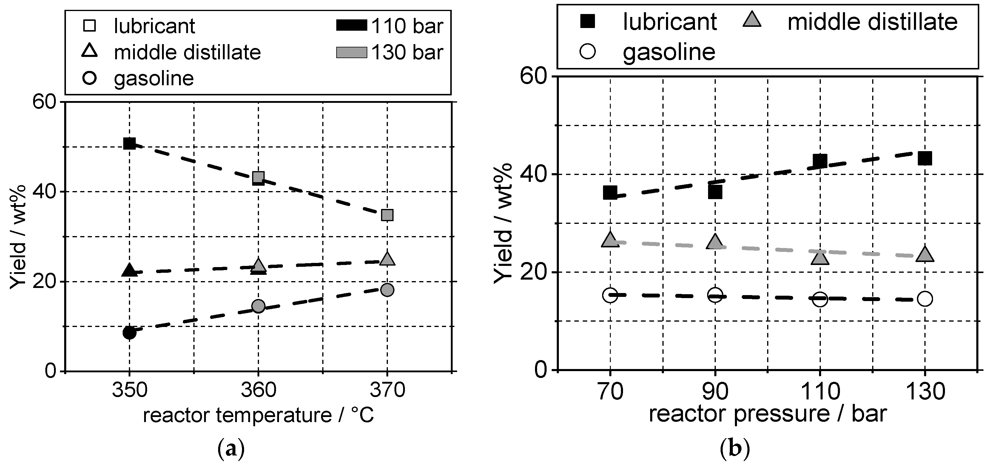
Another critical issue is the yield of the potential lubricating oil. The possible liquid yield loss can occur during the reaction itself with the production of high amounts of carbon gasses or during distillation via evaporation to the vacuum pump. The “de facto” yields are calculated in regards to the inlet flow of the FTW and are depicted in Figure 8. The observed trends are similar to the trends witnessed for the cloud points, indicating a dependency on n-paraffin conversion, resulting in the conclusion that low cloud points can only be achieved under loss of yield. Similar effects for the pour point have been reported by Hsu and Robinson [29].
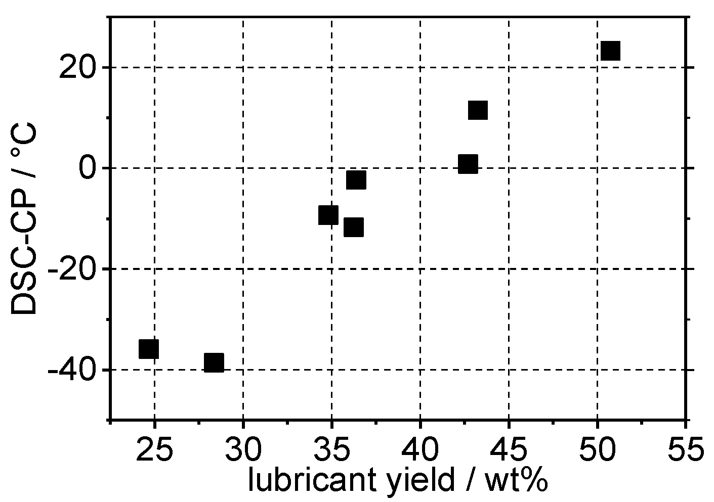
To illustrate this issue, the reduction in cloud point was plotted over the potential lubricant yield (Figure 9). Two additional successfully conducted measurements were added (Appendix C, Samples 8 and 9) to verify the following trends at low yield and cloud points. DSC-CP and Yield decrease simultaneously. Higher quality base oil will therefore come at the cost of lower oil return. This effect is independent from reaction temperature or pressure. This concludes a general opposite trend between yield and quality of the base oil. How this dependency will be afflicted by catalyst choice or LHSV variance will be investigated in future studies. It has been shown that catalysts such as ZSM-5 (MFI) generate less lubricant at similar pour points than a SAPO catalyst would [29].
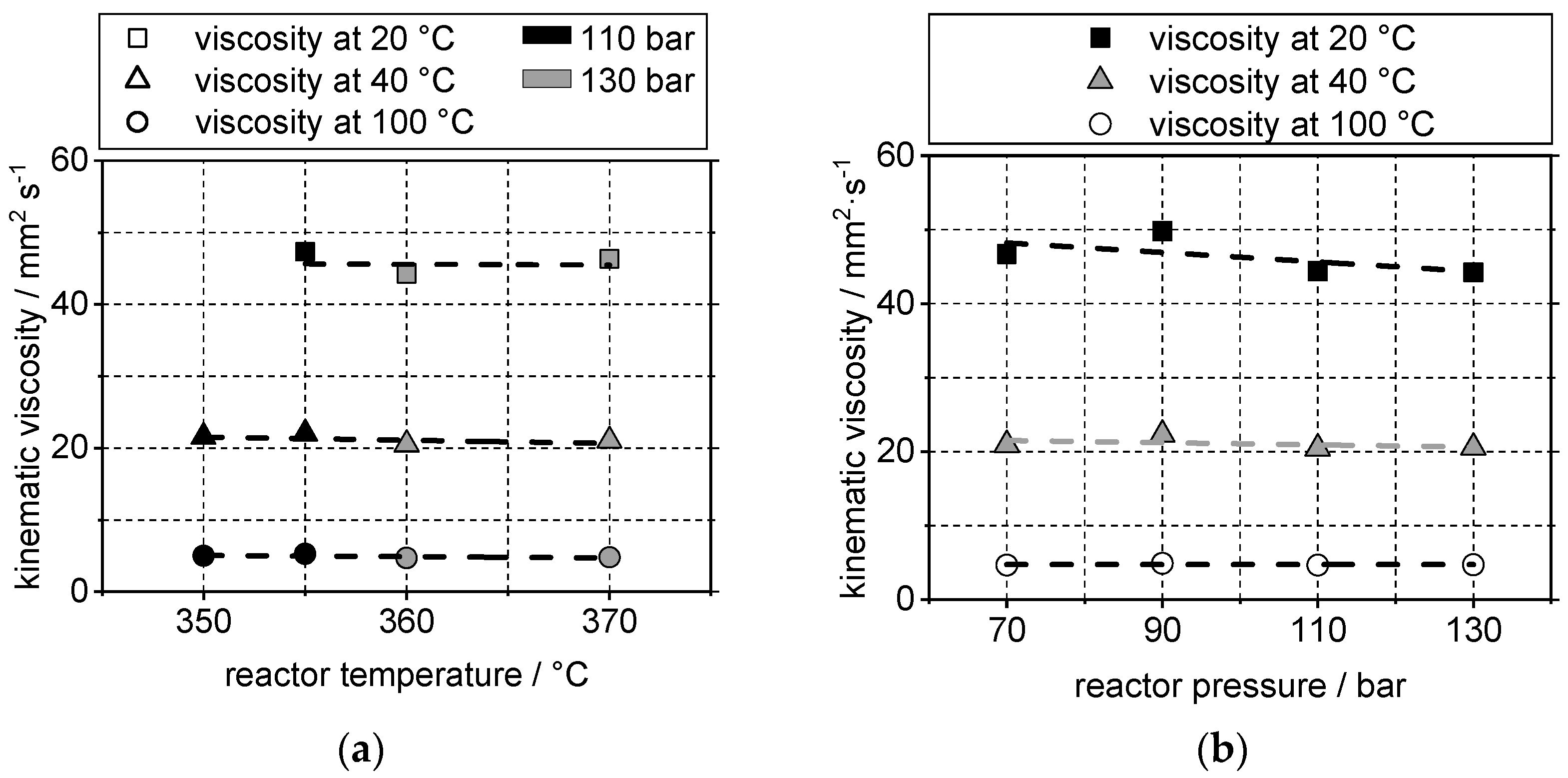
While there are clear dependencies between the oil yields and reaction parameters, the same could not be observed for the corresponding viscosity. The fluctuation of viscosity measured at 20 °C was mostly between 41–50 mm2/s. In the above presented temperature and pressure ranges, barely any trends are observable as depicted in Figure 10. Those trends are not significant enough to have an impact on the oil quality overall. A significant decrease could only be observed for Sample 8 (Appendix C), which might be due to higher catalyst activity for it being produced on a recently regenerated catalyst bed. Yet the measured value for the cloud point of the lubricant and middle distillate was consistent with the expected values, as it will be presented in Section 4.3.

4.3. Determination of Cloud Point Using Composition of the Gasoline Fraction

A major issue in lubrication oil analytics is the determination of molecular composition in the mixture. The longer the chain of the molecule, the more isomers and other by-products are possible. A highly isomerised product might not be separable by gas chromatography and requires more sophisticated measurements such as thin film chromatography or high power liquid chromatography. Even if the analytics are available, one major issue is the potential modelling of the fractions with high molecular weight because of unavailable datasets for the produced isomers. On the contrary, the analytics and modelling of products with lower molecular weight has been conducted [43].
The resulting gasoline was analysed regarding its molecular composition and compared to the cloud point of the corresponding lubricant fraction. Figure 11 shows the DSC-CP for lubricant and middle distillate against the n-paraffin and naphthene content within the conforming gasoline fraction. It can be observed that the cloud point increases simultaneously with n-paraffins in the fuel fraction. The trend is more significant for the lubricants than for the middle distillate. This indicates that the chemical equilibrium of n-paraffins and isoparaffins is comparable within the different boiling ranges. A high n-paraffin content in the gasoline will correspond to a high n-paraffin content in the lube fraction and will therefore begin to crystallise at higher temperatures.
A similar but steeper trend can be observed for the naphthenic components. High molecular weight naphthenes are generally decent lubricant components and desirable over n-paraffins for improvement of the cold flow properties.
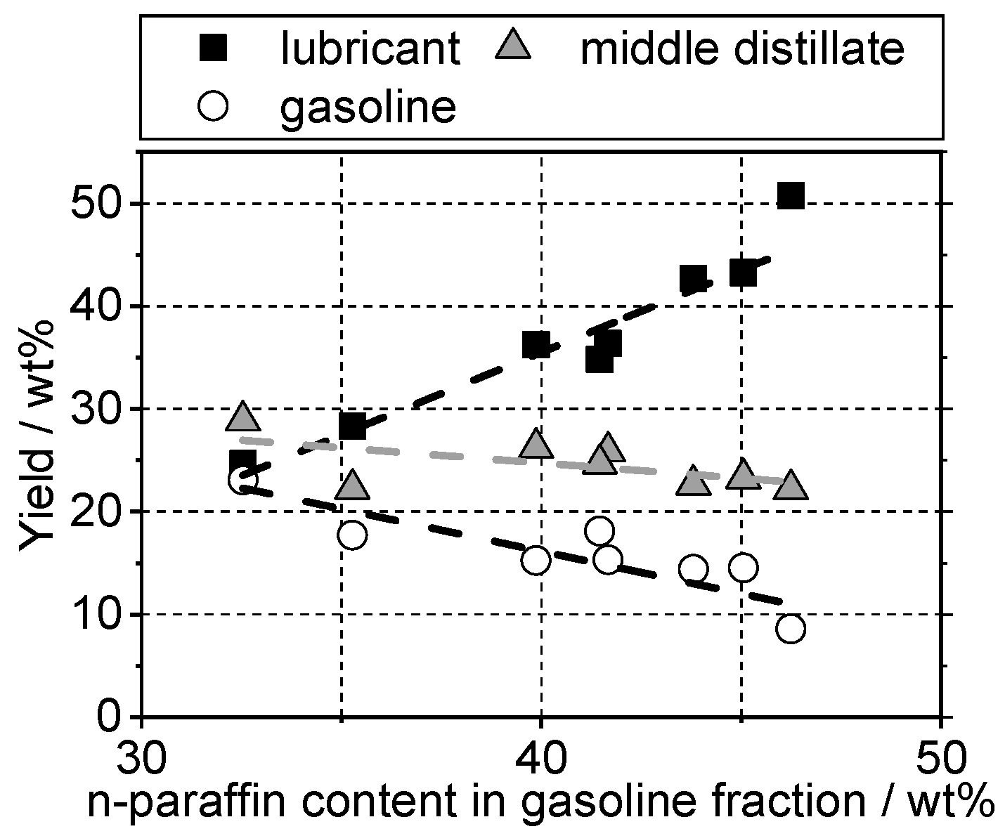
This method even allows the description of the expected liquid yields (Figure 12). At high n-paraffin content, the highest yields are to be gathered. With the reaction progressing and conversion of n-paraffins through isomerisation and cracking, the yields for gasoline increases, while the middle distillate mostly stays the same.

5. Conclusions

In this work, the general production process of base oil from FT waxes was presented. A method for the determination of cloud point using differential scanning calorimetry was applied. It was shown that lubricating oil can be produced by minimal reduction in boiling ranges, while simultaneously reducing the cloud point and subsequently other cold flow properties significantly. It was also shown that the viscosity was hardly reliant on changing reaction parameters. The dependency of cloud points and base-oil yields on reaction parameters, such as temperature and pressure, was investigated and presented. A clear correlation between yield loss and reduction in cloud points could be established. A method for the determination of cloud points through analysis of the distilled gasoline fraction was presented. This would open up different methods for modelling cold flow properties of lubricating oils, while only relying on calculating and analysing the gasoline fraction. These assumptions need to be verified in future studies. In particular, a dependence on different catalyst materials needs to be established.

Author Contributions

The experiments were conceptualised by P.N.; the experimental investigation was performed by P.N., D.G. and H.M.; the manuscript was drafted by P.N.; supervision and funding for this research was provided by R.R. All authors have read and agreed to the published version of the manuscript.

Funding

This research received no external funding.

Data Availability Statement

No application.

Acknowledgments

This paper is dedicated to Hans Schulz on the occasion of his 90th birthday.

Conflicts of Interest

The authors declare no conflict of interest.

Appendix A

Table A1. Calibration equation for CP determination via DSC.
T C = a · T M + b
With:
TMab
<−12.9 °C0.78410.8216
>−12.9 °C
<2.5 °C
0.99003.0611
>2.5°C0.97013.2361

Appendix B

Table A2. Carbon gas composition during hydroconversion of FT-waxes at pH2 = 68–75 bar, TR = 370 °C; LHSV = 0.75 h−1.
ComponentAmount
Methane0.48 wt%
Ethane0.14 wt%
Propane5.26 wt%
Butanes7.10 wt%
  n-Butane  03.98 wt%
  2-M-Propane  03.13 wt%
Pentanes3.67 wt%
  n-Pentane  01.64 wt%
  2-M-Butane  02.02 wt%
Hexanes1.22 wt%
  n-Hexane  00.45 wt%
  2-M-Pentane  00.51 wt%
  3-M-Pentane  00.26 wt%
Heptanes0.29 wt%
  n-Heptane  00.08 wt%
  2-M-Hexane  00.09 wt%
  3-M-Hexane  00.12 wt%
Liquid product mix77.18 wt%
  Lubricant
  (CP = −35.9 °C)
  24.68 wt%
  Middle distillate
  (CP = −55.6 °C)
  28.88 wt%
  Gasoline  23.10 wt%
  Distillation loss  00.53 wt%
95.34 wt%

Appendix C

Table A3. Results table.
SampleReactor Temperature
(°C)
Reactor
Pressure
(bar)
Cloud Point
(°C)
Reformulyzer Analysis
(wt%)
Kinematic Viscosity
(mm2/s)
Liquid Yields
(wt%)
LubricantMiddle DistillateNaphthenesiso-Paraffinsn-Paraffins20 °C40 °C100 °CLubricantMiddle DistllateGasoline
136070−11.7−44.64.3855.6039.8746.720.94.736.226.215.3
236090−2.4−35.44.2354.0241.6749.822.34.936.425.915.3
33601100.8−42.83.7852.3643.8044.420.54.742.722.614.4
435011023.3−23.93.5650.1146.24-21.65.050.722.28.6
535511016.8−25.33.4549.3844.7747.322.05.346.722.411.5
636013011.5−36.83.3751.3545.0644.220.64.743.323.214.5
7370130−9.3−42.63.2955.2041.4646.321.14.834.824.718.1
837068.75−35.9−55.65.5961.7232.5433.615.73.824.728.923.1
938050−38.6−59.65.3858.8635.2841.118.94.228.422.217.7

References

  1. German Federal Government, Effectively Reducing CO2 Emissions. 2020. Available online: https://bit.ly/3wivKDO (accessed on 6 July 2021).
  2. Eckert, V.; Heinrich, M. German Retail Gas Prices to Rise in 2021 due New CO2 Tax: Portal. 2020. Available online: https://reut.rs/3yqqAqH (accessed on 6 July 2021).
  3. Caspeta, L.; Buijs, N.A.A.; Nielsen, J. The role of biofuels in the future energy supply. Energy Environ. Sci. 2013, 6, 1077–1082. [Google Scholar] [CrossRef] [Green Version]
  4. Ripfel-Nitsche, K.; Hofbauer, H.; Rauch, R.; Goritschnig, M. BTL—Biomass to liquid (Fischer Tropsch process at the bio-mass gasifier in Güssing). In Proceedings of the 15th European Biomass Conference & Exhibition, Berlin, Germany, 7–11 May 2007. [Google Scholar]
  5. González, M.I.; Eilers, H.; Schaub, G. Flexible Operation of Fixed-Bed Reactors for a Catalytic Fuel Synthesis-CO2 Hydrogenation as Example Reaction. Energy Technol. 2016, 4, 90–103. [Google Scholar] [CrossRef]
  6. Pöhlmann, F.; Jess, A. Influence of Syngas Composition on the Kinetics of Fischer-Tropsch Synthesis of using Cobalt as Catalyst. Energy Technol. 2015, 4, 55–64. [Google Scholar] [CrossRef]
  7. Puskas, I.; Hurlbut, R. Comments about the causes of deviations from the Anderson–Schulz–Flory distribution of the Fischer–Tropsch reaction products. Catal. Today 2003, 84, 99–109. [Google Scholar] [CrossRef]
  8. Snell, R. Deviations of Fischer-Tropsch products from an Anderson-Schulz-Flory distribution. Catal. Lett. 1988, 1, 327–330. [Google Scholar] [CrossRef] [Green Version]
  9. Jess, A.; Wasserscheid, P. Chemical Technology. In An Integral Textbook; Wiley-VCH: Weinheim, Germany, 2013; ISBN 978-3-527-30446-2. [Google Scholar]
  10. Van der Laan, G.; Beenackers, A.A.C.M. Kinetics and Selectivity of the Fischer–Tropsch Synthesis: A Literature Review. Catal. Rev. 1999, 41, 255–318. [Google Scholar] [CrossRef]
  11. Leckel, D. Diesel Production from Fischer−Tropsch: The Past, the Present, and New Concepts. Energy Fuels 2009, 23, 2342–2358. [Google Scholar] [CrossRef]
  12. Gill, S.; Tsolakis, A.; Dearn, K.D.; Fernández, J.R. Combustion characteristics and emissions of Fischer–Tropsch diesel fuels in IC engines. Prog. Energy Combust. Sci. 2011, 37, 503–523. [Google Scholar] [CrossRef]
  13. Miller, S.J.; Shah, N.; Huffman, G.P. Conversion of Waste Plastic to Lubricating Base Oil. Energy Fuels 2005, 19, 1580–1586. [Google Scholar] [CrossRef]
  14. De Klerk, A. Catalysis in the Refining of Fischer-Tropsch Syncrude; RSC Publishing: Cambridge, UK, 2010; ISBN 978-8-84973-080-8. [Google Scholar]
  15. Bouchy, C.; Hastoy, G.; Guillon, E.; Martens, J.A. Fischer-Tropsch Waxes UpgradingviaHydrocracking and Selective Hydroisomerization. Oil Gas Sci. Technol. Rev. l’IFP 2009, 64, 91–112. [Google Scholar] [CrossRef] [Green Version]
  16. Gamba, S.; Pellegrini, L.A.; Calemma, V.; Gambaro, C. Liquid fuels from Fischer–Tropsch wax hydrocracking: Isomer distribution. Catal. Today 2010, 156, 58–64. [Google Scholar] [CrossRef]
  17. Rossetti, I.; Gambaro, C.; Calemma, V. Hydrocracking of long chain linear paraffins. Chem. Eng. J. 2009, 154, 295–301. [Google Scholar] [CrossRef]
  18. Schulz, H.F.; Weitkamp, J.H. Zeolite Catalysts. Hydrocracking and Hydroisomerization of n-Dodecane. Ind. Eng. Chem. Prod. Res. Dev. 1972, 11, 46–53. [Google Scholar] [CrossRef]
  19. Weitkamp, J. Isomerization of long-chain n-alkanes on a Pt/CaY zeolite catalyst. Ind. Eng. Chem. Prod. Res. Dev. 1982, 21, 550–558. [Google Scholar] [CrossRef]
  20. Royal Dutch Shell plc. Risella X. High-Quality Technical White Oils Based on Gas to Liquids (GTL) Technology. Available online: https://go.shell.com/2RnueBW (accessed on 4 May 2021).
  21. Gerasimov, D.N.; Kashin, E.V.; Pigoleva, I.V.; Maslov, I.A.; Fadeev, V.V.; Zaglyadova, S.V. Effect of Zeolite Properties on Dewaxing by Isomerization of Different Hydrocarbon Feedstocks. Energy Fuels 2019, 33, 3492–3503. [Google Scholar] [CrossRef]
  22. Kobayashi, M.; Saitoh, M.; Togawa, S.; Ishida, K. Branching Structure of Diesel and Lubricant Base Oils Prepared by Isomerization/Hydrocracking of Fischer−Tropsch Waxes and α-Olefins. Energy Fuels 2009, 23, 513–518. [Google Scholar] [CrossRef]
  23. Kobayashi, M.; Togawa, S.; Ishida, K. Properties and molecular structures of fuel fractions obtained from Hydrocracking / Isomerization of Fischer-Tropsch waxes. J. Jpn. Pet. Inst. 2005, 49, 194–201. [Google Scholar] [CrossRef]
  24. Kobayashi, M.; Ishida, K.; Saito, M.; Yachi, H. Japan Energy Corporation. Lubricant Base Oil Method of Producing the Same. U.S. Patent 8.012,342 B2, 6 September 2011. Available online: https://bit.ly/3phwTtk (accessed on 3 June 2021).
  25. Miller, S.J.; Chevron Research and Technology Company. Wax Isomerization Using Catalyst of Specific Pore Geometry. U.S. Patent 5,246,566, 21 September 1993. Available online: https://bit.ly/3uMNVRf (accessed on 3 June 2021).
  26. Bertaux, J.-M.A.; Germaine, G.R.B.; Janssen, M.M.P.; Hoek, A. Shell Internationale Research Maatschappij. Process for producing lubricating base oils. U.S. Patent EP 0776959 A2, 4 June 1997. Available online: https://bit.ly/2S7Az4H (accessed on 3 June 2021).
  27. Sirota, E.B.; Johnson, J.W.; Simpson, R.R.; Exxonmobil Research and Engineering Company. Production of Extra Heavy Lube Oils from Fischer-Tropsch Wax. U.S. Patent 7465389B2, 16 December 2008. Available online: https://bit.ly/2SXXNdt (accessed on 3 June 2021).
  28. Speight, J.G. Hydrocarbons from Petroleum; Elsevier BV: Amsterdam, The Netherlands, 2011; pp. 85–126. [Google Scholar]
  29. Hsu, C.S.; Robinson, P.R. Petroleum Science and Technology; Springer Science and Business Media LLC: Berlin/Heidelberg, Germany, 2019. [Google Scholar]
  30. Haynes, W.M. CRC Handbook of Chemistry and Physics, 93rd ed.; CRC Press: Boca Raton, FL, USA, 2012; ISBN 978-1-4398-8049-4. [Google Scholar]
  31. Pichler, H.; Schulz, H.; Reitemeyer, H.O.; Weitkamp, J. Über das Hydrokracken gesättigter Kohlenwasserstoffe. Erdöl und Kohle Erdgas, Petrochemie Vereinigt mit Brennstoff-Chemie 1972, 25, 494–505. [Google Scholar]
  32. ASTM D2502-14. Standard Test Method for Estimation of Mean Relative Molecular Mass of Petroleum Oils from Viscosity Measurements; ASTM International: West Conshohocken, PA, USA, 2019. [Google Scholar] [CrossRef]
  33. Coutinho, J.; Mirante, F.; Ribeiro, J.; Sansot, J.; Daridon, J. Cloud and pour points in fuel blends. Fuel 2002, 81, 963–967. [Google Scholar] [CrossRef]
  34. Dwivedi, G.; Sharma, M. Impact of cold flow properties of biodiesel on engine performance. Renew. Sustain. Energy Rev. 2014, 31, 650–656. [Google Scholar] [CrossRef]
  35. Deldari, H. Suitable catalysts for hydroisomerization of long-chain normal paraffins. Appl. Catal. A Gen. 2005, 293, 1–10. [Google Scholar] [CrossRef]
  36. Höhne, G. Problems with the calibration of differential-temperature-scanning-calorimeters. Thermochim. Acta 1983, 69, 175–197. [Google Scholar] [CrossRef]
  37. Heino, E.-L. Determination of cloud point for petroleum middle distillates by differential scanning calorimetry. Thermochim. Acta 1987, 114, 125–130. [Google Scholar] [CrossRef]
  38. Rossi, A. Wax and Low Temperature Engine Oil Pumpability. SAE Tech. Paper Ser. 1985, 94, 768–776. [Google Scholar] [CrossRef]
  39. ASTM D4419-90. Standard Test Method for Measurement of Transition Temperatures of Petroleum Waxes by Differential Scanning Calorimetry (DSC); ASTM International: West Conshohocken, PA, USA, 2015. [Google Scholar] [CrossRef]
  40. ASTM F3418-20. Standard Test Method for Measurement of Transition Temperatures of Slack Waxes Used in Equine Sports Surfaces by Differential Scanning Calorimetry (DSC); ASTM International: West Conshohocken, PA, USA, 2020. [Google Scholar] [CrossRef]
  41. ASTM D2500-17a. Standard Test Method for Cloud Point of Petroleum Products and Liquid Fuels; ASTM International: West Conshohocken, PA, USA, 2017. [Google Scholar] [CrossRef]
  42. Claudy, P.; Létoffé, J.-M.; Neff, B.; Damin, B. Diesel fuels: Determination of onset crystallization temperature, pour point and filter plugging point by differential scanning calorimetry. Correlation with standard test methods. Fuel 1986, 65, 861–864. [Google Scholar] [CrossRef]
  43. Pellegrini, L.; Locatelli, S.; Rasella, S.; Bonomi, S.; Calemma, V. Modeling of Fischer–Tropsch products hydrocracking. Chem. Eng. Sci. 2004, 59, 4781–4787. [Google Scholar] [CrossRef]
Figure 1. Mechanism of isomerisation (a) and cracking (b) of long-chain paraffins [15].
Energies 14 04202 g001
Figure 2. Schematic depiction of the reaction network for hydroprocessing of n-paraffins on a catalytic surface [15].
Energies 14 04202 g002
Figure 3. Schematic depiction of the three-phase fixed bed reactor setup at the Engler-Bunte-Institute, Karlsruhe.
Energies 14 04202 g003
Figure 4. Composition of the feed wax.
Energies 14 04202 g004
Figure 5. DSC-Measurement for a commercial paraffin oil (a) and temperature programme for determination of cloud points. mSample = 10 mg, V N2 = 100 mL/min (b).
Energies 14 04202 g005
Figure 6. Boiling ranges of the resulting products after hydroprocessing of FT-wax by simulated distillation.
Energies 14 04202 g006
Figure 7. Influence of reactor temperature (a) and pressure at TR = 360 °C (b), LHSV = 0.75 h−1, H2/wax = 1964 L/L.
Energies 14 04202 g007
Figure 8. Yield loss at different reactor temperature (a) and pressure yield loss at increasing reaction pressure at TR = 360 °C (b); LHSV = 0.75 h−1, H2/wax = 1964 L/L.
Energies 14 04202 g008
Figure 9. DSC-CP over lubricant yield at varying reactor temperatures and pressure.
Energies 14 04202 g009
Figure 10. Kinematic viscosity measured at different reactor temperature (a) and pressure at TR = 360 °C (b); LHSV = 0.75 h−1, H2/wax = 1964 L/L (viscosity at 20 °C for the point at 350 °C, 110 bar was not determined due to its CP being above that temperature).
Energies 14 04202 g010
Figure 11. DSC-CP change of the lubricant and middle distillate fractions against the n-paraffin (a) and naphthene (b) content in their corresponding gasoline fraction.
Energies 14 04202 g011
Figure 12. Yield change of the liquid fractions against the n-paraffin content in their corresponding gasoline fraction.
Energies 14 04202 g012
Table 1. API classifications of lubricant base stock [29].
GroupManufacturing Process
Isolvent processing
IIhydroprocessing
IIIGTL; wax isomerisation, severe hydroprocessing
IVpolyalphaolefins (POA)
Vall other base stocks
Publisher’s Note: MDPI stays neutral with regard to jurisdictional claims in published maps and institutional affiliations.