Article

Primary Research of a New Zero-Liquid-Discharge Technology of Wet Flue Gas Desulfurization Wastewater by Low-Rank Heat from Flue Gas

1
State Key Laboratory of Power Systems, Department of Energy and Power Engineering, Tsinghua University, Beijing 100084, China
2
China Energy Longyuan Environmental Protection Co. Ltd., Haidian District, Beijing 100039, China
*
Author to whom correspondence should be addressed.
Energies 2021, 14(14), 4259; https://doi.org/10.3390/en14144259
Submission received: 11 June 2021 / Revised: 10 July 2021 / Accepted: 13 July 2021 / Published: 14 July 2021
(This article belongs to the Section B: Energy and Environment)

Abstract

:
Wet flue gas desulfurization (WFGD) wastewater treatment is a key problem in coal-fired plants. Traditional chemical precipitation methods cannot reach zero-liquid discharge (ZLD). In this paper, a new technology using the low-rank heat from flue gas to concentrate the wastewater for ZLD is proposed. A scrubber was built to verify the concentrating process, and the characteristics of the concentrated water were analyzed. The concentrated water was neutralized by adding Ca(OH)2 to raise the pH value. The wastewater can be concentrated 10~25 times to reduce the flow rate. The characteristics of the concentrated wastewater were studied by dosing lime. Then, liquid and solids were separated by filter pressing, the liquid was mainly composed of CaCl2, which accounts for 73.6%. The sludge is composed of CaSO4 and Mg(OH)2, depending on the lime consumption of the dosing process. Finally, the filter liquor after the filter press was mixed with ash to reach zero liquid discharge, and the sludge could be burnt after mixing with the coal or disposed by third-part vendor. This technology is demonstrated in one 600 MW unit and shows a high system reliability. The clean water is recycled by the WFGD wastewater during the evaporation. Binding on the environmental policies and large market demand of the WFGD wastewater, this technology shows a great application prospect in the future.

1. Introduction

The limestone–gypsum wet flue gas desulfurization (WFGD) uses limestone as an absorbent to capture SO2 in the flue gas, and produces gypsum as a byproduct [1,2,3,4,5,6,7]. After long operation, the chloride ion, heavy metals and other impurities in the flue gas are enriched in the circulating slurry, which can cause the material corrosion, decrease SO2 removal rate and affect the quality of gypsum [8]. To control the concentrations of such things WFGD wastewater must be discharged externally [9,10].
The traditional method of the WFGD wastewater treatment is chemical precipitation (also called the triple-tank process) [11,12,13,14,15]. By adding the sodium carbonate, organic sulfur and flocculating agent (PAM) to the WFGD wastewater, Ca2+, Mg2+ and the heavy metals are precipitated from the wastewater. However, most salt irons including chloride ions remain in the filtered solution, which is directly discharged from the power plant [16,17]. This may cause secondary pollution to the surface water environment. In 2017 the local government in China issued a Zero-emission regulation of the wastewater in coal-fired plants. In the future, the WFGD wastewater treated by the chemical precipitation can no longer be discharged from the power plant. Therefore, cheap and reliable zero liquid discharge (ZLD) technology of WFGD wastewater is needed urgently.
Since the desulfurization wastewater contains a large amount of suspended solids, chloride ions and salts, there are relatively few available options for ZLD of WFGD waste water [9].
The first method is preprocessing + hardness softening + Reverse Osmosis (RO) membrane concentration + multi-effect evaporation. Firstly, the wastewater is treated by traditional chemical precipitation methods. Then, lime and sodium carbonate are dosed to soften the water by decreasing the hardness. Almost all the calcium and magnesium ions should be removed to fulfill the requirement of downstream RO membrane. Sodium carbonate consumed during the softening process cost lots of money. Then, the waste water is concentrated by the RO membrane to the minimum the flow rate; this can save the steam consumption and expense of the evaporation process. The concentration ratio of the RO membrane is generally 3~4 times due to the high TDS of the wastewater [11,12]. After the concentration, the clean water is reused in the power plant. The concentrated water is transferred to evaporation system in which the waste water turns into salt solids. The salt is mainly composed of sodium chloride and sodium sulfate. Multi-effect evaporation is widely used for the evaporation process to save the steam. However, as the concentration ratio of the RO membrane is very low, the method will cause large amount of steam [13,14].
Another method for the wastewater treatment is direct drying process. High-temperature flue gas about 300~400 °C is used as drying medium, and the spray drier device is used to evaporate the wastewater [15]. The outlet flue gas and salt particle are mixed with flue gas before the Electrostatic Precipitator. The salt is mixed with dust ash and finally enters the building materials market. As the direct evaporate drying process of the wastewater cost large amount of hot flue gas, the operation expense is very high [16,17].
In this paper, a new strategy by using the low-rank heat from flue gas to concentrate the WFGD wastewater is proposed. Most water in the wastewater evaporated in the concentrating scrubber enter the WFGD system. This can save the fresh water consumption of the WFGD. The concentrated wastewater containing high chloride ion is mixed with the ash collected by the ESP to reach zero-liquid discharge [18,19,20,21]. Additionally, small amount of sediments can be burnt by mixing with coal or just trucked out of the power plant to third-party disposal vendor. There is no wastewater discharged from the power plant and actual achieve the wastewater’s zero emission.

2. Concept of the New WFGD Wastewater Zero-Emission Technology

The WFGD wastewater has some specific features comparing with the others sources of wastewater in the power plant [2,9,11].
(1)
Low pH value about 4.5~6.0;
(2)
High Mg2+ (1000~5000 mg/L) and Ca2+ (2000~4000 mg/L) concentrations, which easily cause the material scale formation;
(3)
High concentration of the chloride ions, about 6000~20,000 mg/L, which easily cause the material corrosion and difficult to remove;
(4)
High concentration of the TDS (total dissolved solids) (10,000~40,000 mg/L);
(5)
The large amount of wastewater. For example, in a typical 600 MW boiler unit, the wastewater flow rate is about 5~10 ton/h; the wastewater composition varies with the coal type and the limestone type, especially for the Mg2+ and chloride ions.
All these characteristics make WFGD wastewater the most complex and difficult environmental problem to handle in the power plant. How to deal with it is the key problem to reach ZLD in the power plant.
The concept design of the new WFGD wastewater treatment technology is shown in Figure 1. The wastewater is treated in three steps:
(1)
The preprocessing stage: The original WFGD wastewater goes into the cyclone and the flocculation basin to separate the liquid and the solids firstly to decrease the solids content. The filtered solution with solids concentration less than 1% can be used as the raw material of next concentrating process. The higher the solids concentration in the filtered solution, the higher the risk of the nozzle plugging in the concentrating scrubber in the next stage.
(2)
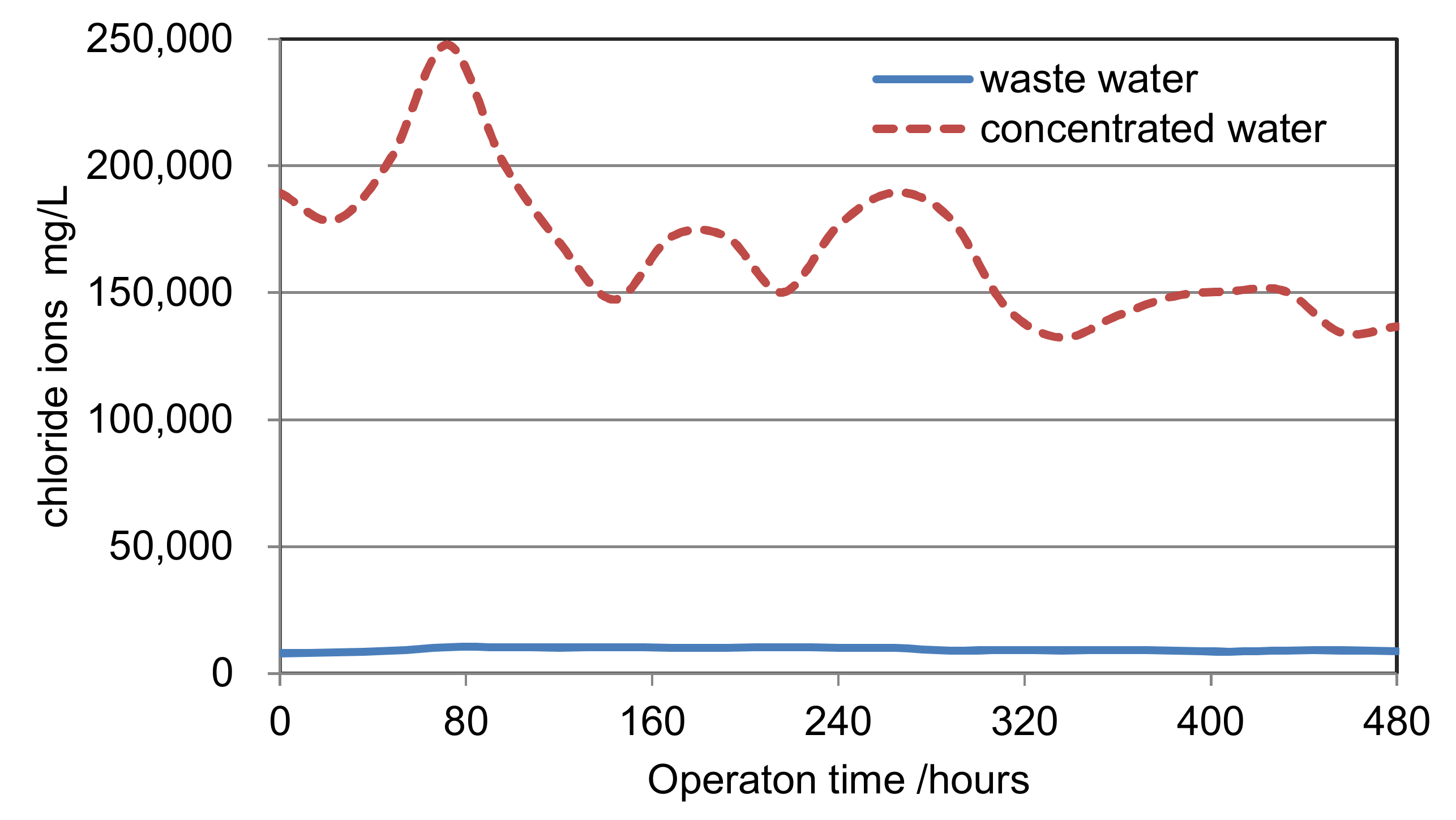
The concentrating process: A concentrating scrubber is designed before WFGD in the concentrating process. The 120~180 °C flue gas before WFGD is the heat source of the concentrating process. The WFGD wastewater is cyclically sprayed downstream in the concentrating scrubber, and evaporated by the heat of the flue gas. A boost fan is used to overcome the resistance of the scrubber. In this way, the wastewater can be concentrated into the condensed slurry, which has the low pH value of 1~2 and the concentration of chloride ion about 150,000~200,000 mg/L. The concentration rate has a wide range of 0~25 due to the flexibility of scrubber. This process can greatly reduce wastewater discharge flow rate to next stage.
(3)
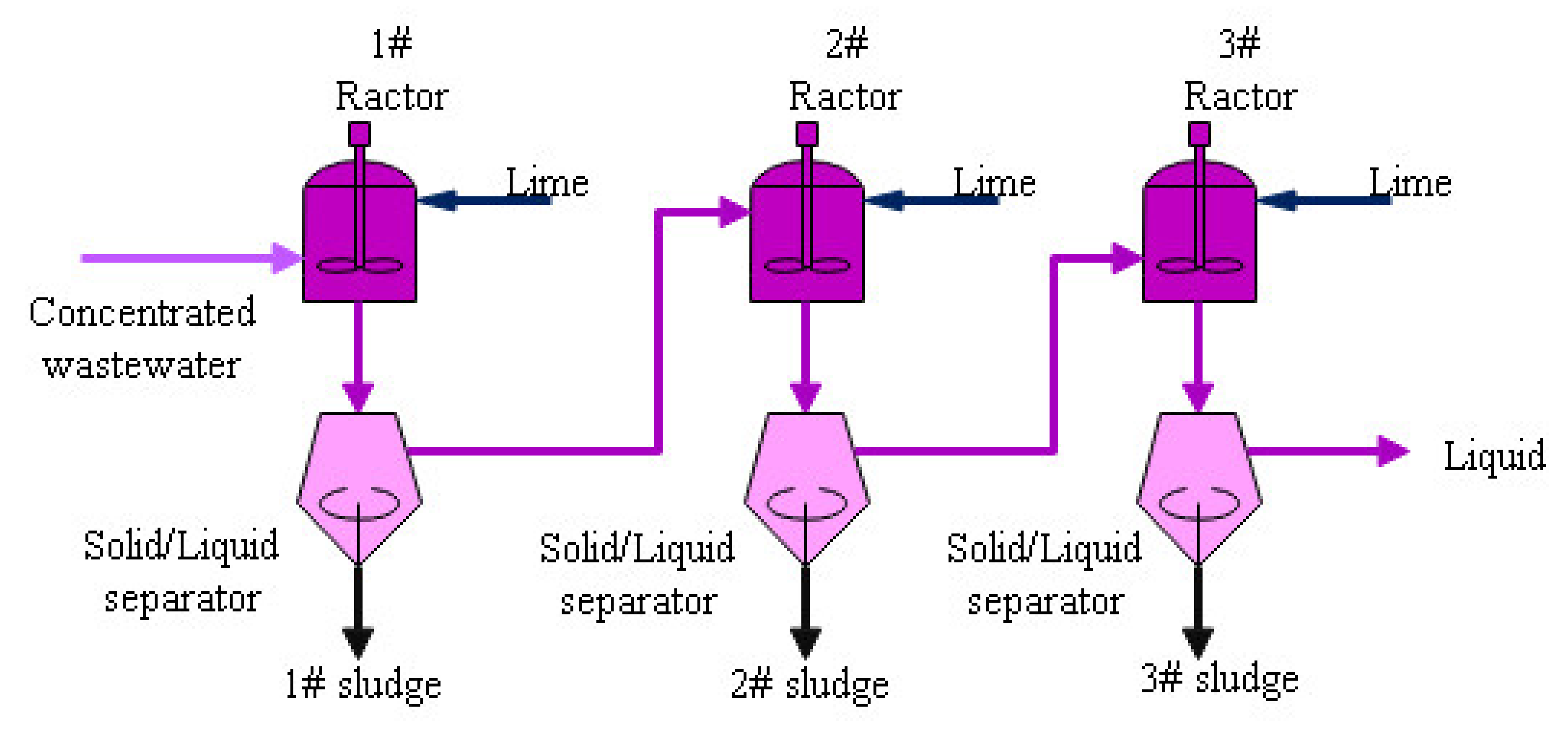
The chemical dosing process: The concentrated water is neutralized by adding the Ca(OH)2 to raise the pH value. In this process, most Ca2+, Mg2+ and SO42− in the water converted into Mg(OH)2 and CaSO4. A filter press is used to separate the liquid and the sludge. The final filtered liquor is mixed with the ash collected by the ESP to reach zero liquid discharge. The sludge can be mixed with coal or just trucked out of the power plant to third-party disposal vendor.

3. The Pilot Plant Test to Verify the Concentrating Process

In order to verify the concentrating process, a pilot plant of concentrating scrubber was built in the power plant. As shown in Figure 2, the concentrating scrubber, with the diameter of 2.5 m and the height of 24 m, has one inlet duct, two spray banks, one demister and one outlet. The flue gas coming from the inlet was used as the heat source to condense the WFGD wastewater. Two spray banks with 12 nozzles were set in the middle of the scrubber to provide the good liquid distribution in the scrubber. The demister was set at the top of the scrubber to eliminate the tiny mist in the wet flue gas. The outlet wet flue gas was induced to the WFGD absorber.
The pilot test was operated for 3 months to verify the concentrating process. All the equipment was worked well during the test. The condition of the flue gas characters at the concentrating scrubber inlet and the outlet are shown in Table 1.
As shown in Table 1, the total system resistance of the concentrating scrubber is about 1.0 kPa. The resistance can be overcome by boost fan before the scrubber for process design. The saturation temperature of the outlet flue gas is much lower than that of the inlet. This is because the waste water is vaporized in the concentrating scrubber. The gaseous water is carried away by the wet flue gas, which makes the flow rate and water content in the outlet flue gas a little higher than those in the inlet. The data also shows that the WFGD wastewater can capture HCl and the dust in the flue gas, but cannot absorb SO2. This can be explained by the low pH value of the slurry in Table 2.
In the process of water vaporization, the wastewater is concentrated in the slurry tank. By adjusting the outflow rate of the condensed slurry tank, the wastewater can be condensed at different times. The maximum condensed rate can achieve 25 times in this project and 10~15 times is more reasonable for the economic concern and the risk of the nozzle plugging of the spray bank in the scrubber. The main salt ions concentrations of the WFGD wastewater and concentrated water are shown in Table 2, with the condensed rate about 20 times.
As shown in Table 2, after 20 times concentrated, concentrated water has extremely lower pH than original wastewater, and that is why it has no ability to absorb SO2 in the flue gas. According to the theory and experience of limestone/gypsum FGD, the slurry cannot absorb SO2 when the pH is lower than 4.0.
The Cl, Na+ and K+ concentrations in sample 2 are almost 20 times as much as that in sample 1, which means almost all these ions are left in the condensed slurry. The concentrations of Ca2+, Mg2+, SO42− and F in sample 2 are 1.83, 11.4, 2.03 and 2.67 times as much as those in sample 1, which means the ions form sediments during the concentrating process.
For the limestone/gypsum desulfurization wastewater, calcium sulfate and calcium fluoride are saturated for high Ca2+ in the water. During the concentration process, the concentration of calcium ions, sulfate ions and fluoride ions in the wastewater continue to increase, which will produce calcium sulfate (CaSO4) and calcium fluoride (CaF), as shown in following chemical reaction formula.
Ca2+ + SO42− → CaSO4
Ca2+ + F1− → CaF
As the low solubility of these two compounds, sediment will form and increase the solid content in the slurry. Therefore, the concentration rate of Ca2+, SO42− and F is much smaller than that of the wastewater or the chloride ions.
Some magnesium sulfate (MgSO4) will also form crystals with the increase of the concentration rate (Mg2+ + SO42− → MgSO4). As the solubility of magnesium sulfate (MgSO4) is higher than CaSO4 and CaF, the concentration rate of magnesium ions is higher than that of Ca2+, SO42− and F. However, the value is less than that of Cl Na+ and K+. This is consistent with the crystallization process of brine of high TDS [22,23].
The 12-Days operation history of the chloride ions in the wastewater and concentrated water is shown in Figure 3. In this figure, the change rate of chloride ions verifies the reliability and flexibility of the scrubber for the concentrate process.
For traditional methods such as multi-effect evaporation or membrane method, softening agents such as the sodium carbonate are used to maintain the TDS in water at a suitable range to prevent fouling. The operation cost of adding soluble salt is very high [24,25].
While for the concentrating method in the scrubber, there are no extra chemicals used to decrease hardness of water, the concentrating scrubber has strong ability to adapt the wastewater variation by adjusting the heating rate. As the concentrating scrubber is similar with the wet FGD absorber, the operation mode is much easier for the FGD operators to learn in the power plant.
After the concentrating process, the volume flow rate of the concentrated slurry is 1/10~1/25 of original WFGD wastewater flow rate. The concentrated rate of the process is much higher than membrane or multiple-effect evaporator method. Therefore, we can choose compact equipment for downstream process, which can save the investment. For the concentrating process, chemical reagent for softening the wastewater hardness and steam is not used. There is only low-rank waste heat in flue gas is used to condense the wastewater. Therefore, the operation fee is much lower than traditional process [12,13,14].

4. Small-Scale Experiment of the Chemical Dosing Process

After the concentrating process, the concentrated wastewater has extremely low pH value and high chlorine concentration, as shown in Table 1. Ca(OH)2 is used to neutralize the slurry and precipitate some salt ions In the chemical dosing process. In order to investigate the characteristic of the concentrated water, the small-scale experiment is conducted as shown in Figure 4.
Lime is dosed into the reactor to react with the concentrated wastewater in three stages. For each stage, filter press was used to separate the solid and liquid in the reactor.
The pH value in the 1# reactor was controlled to be 8.26. At this pH environment, most SO42− is precipitated by Ca2+ to produce CaSO4 as shown in following equation:
Ca2+ + SO42− → CaSO4
Due to the low solubility, most calcium sulfate turns into sludge. Meanwhile, Mg (OH)2 is also produced with the increase of the pH value.
Mg2+ + OH → Mg(OH)2
In the 2# and 3# reactor, Ca(OH)2 is continuously dosed to precipitate Mg2+. According to former research, a majority of Mg2+ can be precipitated at the pH value about 10~11 [21]. As shown in Table 3, when pH reaches 8.7 in the 2# reactor, a large amount Mg(OH)2 is formed, the Mg(OH)2 accounts for the largest part of the sludge. There is only a small part of unreacted lime in the sludge.
In the 3# reactor, the pH value is raised to 10.5 by adding excess Ca(OH)2 into the slurry. In this way, most Mg2+ formed in to Mg(OH)2. For the 3# sludge, the moisture content is 42%, the mass fraction of Ca(OH)2 is about 51.52%. Using the mass flow rate, we can calculate the total Mg2+ conversion rate to Mg(OH)2 is about 88% after the pH reaches 10.5.
From Table 3, we can also see the sludge moisture content is about 40~50%. The moisture content of the three sludge samples varies. This is because Mg(OH)2 particles have a very small particle size. These particles are very difficult to separate by the filter press [23,24].
For the typical 600 MW unit, coal consumption is 200 ton/h. After the concentrating and subsequent process, the sludge is less than 50 kg/h, which occurs than 0.025% of the coal consumption of the boiler. Therefore, this sludge can be mixed with the coal and burnt in the boiler. The method has been verified in one 600 MW business unit. Another option for the sludge is third-party sludge disposal vendor. This will cause extra expense for the treatment.
The final filtered solution composition from filter press is shown in Table 4. The main ions in the filtered solution are Ca2+ and Cl.
By drying the filtered solution into solid, the compositions are also analyzed and shown in Table 5. The most abundant substance in the dried solid is CaCl2, which accounts for 73.6%. The Ca(OH)2 in the solids is a bit high and reach 10.02%. This is because the excessive presence of Ca(OH)2. Hydrochloric acid can be used to change Ca(OH)2 into CaCl2 in engineering design.
As shown in Table 5, the final filtered solution can be a raw material of CaCl2 production. Another simple process to handle, the liquid is mixed into the ash collected by the Electrostatic Precipitator to reach zero liquid discharge [25,26,27].

5. Key Parameter of Demonstration Project of the Wastewater Treatment Process

This technology proposed by the paper is demonstrated in one 600 MW coal-fired unit. The key parameter of the demonstration project is shown in Table 6. The process of the project is same with the concept design in Figure 1.
As shown in Table 6, for a typical 600 MW boiler unit, the WFGD wastewater is about 5 ton/h (chloride irons 20,000 mg/L). After concentrating and chemical dosing process, the filter wastewater is less than 0.5 ton/h. While the total dust ash from ESP is over 40 ton/h. The increase of moisture content of the dust ash is about 1.25%. The chlorine content in the dust ash due to the salt is about 0.25%. This tiny content in the dust has no effect for the usage of dust ash for concrete [22,23,24,25,26].

6. Conclusions

In this paper, a concept of a new WFGD wastewater treatment technology was proposed and verified. It uses the low-rank heat from flue gas to concentrate the WFGD wastewater by 10~20 times. The concentrated wastewater characteristics are studied, which include high acid and corrosion. Additionally, lime is dosed to raise the pH value of the concentrated wastewater. Then, a filter press was used to separate liquid and sludge. The sludge is mainly composed of the CaSO4, Mg(OH)2 and unreacted Ca(OH)2. The liquid is mainly composed of CaCl2, which can be mixed with dust ash from ESP to reach ZLD.
Only low-rank heat and cheap lime is used to reach ZLD in the process, this can lower the wastewater treatment expense. Therefore, this is an innovative work in the field of the wastewater treatment and could achieve wastewater zero emission. The experiment data and key parameter can be used to guide future engineering design.

Author Contributions

X.Y. (Xuan Yao) performed data process, modeling, simulation and edited the draft with guidance from M.Z. and H.Y.; B.D. and X.Y. (Xinhua Yang) checked the language, style of manuscript and made a contribution to the revision of manuscript. All authors have read and agreed to the published version of the manuscript.

Funding

This research received no external funding.

Institutional Review Board Statement

Not applicable.

Informed Consent Statement

Not applicable.

Acknowledgments

This work was financial supported by the National Natural Science Foundation of China (Project Number: U1810126) and C9 University Science and Technology Project (201903D421009).

Conflicts of Interest

The authors declare no conflict of interests.

References

  1. Hu, G.; Dam-Johansen, K.; Wedel, S.; Peterhansen, J. Review of the direct sulfation reaction of limestone. Prog. Energy Combust. Sci. 2006, 32, 386–407. [Google Scholar] [CrossRef]
  2. Chowdhury, B.H. Emission Control Alternatives for Electric Utility Power Plants. Energy Sources 1996, 18, 393–406. [Google Scholar] [CrossRef]
  3. Karatepe, N. A Comparison of Flue Gas Desulfurization Processes. Energy Sources 2000, 22, 197–206. [Google Scholar] [CrossRef]
  4. Tomás-Alonso, F. A New Perspective about Recovering SO2 Offgas in Coal Power Plants: Energy Saving. Part III. Selection of the Best Methods. Energy Sources 2005, 27, 1051–1060. [Google Scholar] [CrossRef]
  5. Brogren, C.; Karlsson, H.T. The impact of the electrical potential gradient on limestone dissolution under wet flue gas desulfurization conditions. Chem. Eng. Sci. 1997, 52, 3101–3106. [Google Scholar] [CrossRef]
  6. Ersoy-Meriçboyu, A. Removal of Sulphur Dioxide from Flue Gases. Energy Sources 1999, 21, 611–619. [Google Scholar] [CrossRef]
  7. Hlincik, T.; Buryan, P. Evaluation of limestones for the purposes of desulphurisation during the fluid combustion of brown coal. Fuel 2013, 104, 208–215. [Google Scholar] [CrossRef]
  8. United States Enviromental Protection Agency. Steam Electric Power Generating Point Source Category: Final Detailed Study Report; Environmental Protection Agency: Washington, DC, USA, 2009.
  9. Higgins, T.E.; Sandy, T.; Givens, S.W. Flue Gas Desulfurization Wastewater Treatment Primer. Power 2009, 153, 34. [Google Scholar]
  10. Ma, S.; Chai, J.; Chen, G.; Yu, W.; Zhu, S. Research on desulfurization wastewater evaporation: Present and future perspectives. Renew. Sustain. Energy Rev. 2016, 58, 1143–1151. [Google Scholar]
  11. Dong, X.F.; Shen, G.F.; Zhou, X.X.; Guo, J.J.; Zhang, X.Y.; Wu, W.L. The Problems and Suggestions of the Desulfurization Wastewater Treatment System during the Operation. Adv. Mater. Res. 2012, 599, 521–524. [Google Scholar] [CrossRef]
  12. Han, F.C.; Wang, X.; Zhang, R.; Yang, L.; Wang, W.F. Optimized Reconstruction of Limestone-Gypsum Wet Flue Gas Desulfurization Wastewater Treatment Process. China Water Wastewater 2016, 32, 99–102. [Google Scholar]
  13. Kang, M.; Deng, J.; Chen, D.; Pan, L. Analysis on the Feasibility of Desulfurization Wastewater Evaporation Treatment in Flue Gas Duct Without Pollution Discharge. J. Civ. Archit. Environ. Eng. 2013, 35, 238–240. [Google Scholar]
  14. Wang, R.D.; Ye-Ran, L.I.; Guo-Quan, G.U.; Feng-Jun, X.U. FGD Wastewater Treatment Using Improved Chemical Precipitation in Jingmen Power Plant Pollut. Control Technol. 2012, 25, 13–15. [Google Scholar]
  15. Fu, J.; Hu, N.; Yang, Z.; Wang, L. Experimental study on zero liquid discharge (ZLD) of FGD wastewater from a coal-fired power plant by flue gas exhausted heat. J. Water Process. Eng. 2018, 26, 100–107. [Google Scholar] [CrossRef]
  16. Zakrzewska-Trznadel, G. Advances in membrane technologies for the treatment of liquid radioactive waste. Desalination 2013, 321, 119–130. [Google Scholar] [CrossRef]
  17. Chunsong, Y.E.; Luo, S.; Zhang, X.; Xia, M.; Huang, J. Key problems and developing trend of zero discharge technology of desulfurization wastewater. Therm. Power Gener. 2016, 45, 105–108. [Google Scholar]
  18. Liu, H.Y.; Xia, H.X.; Jiang, C.Y.; Xiao-Bing, G.U.; Ye-Hong, L.I. Research Advances in Wet Flue Gas Desulfurization Wastewater Treament Technology in Coal-Fired Power Plant. Environ. Eng. 2016, 34, 31–35. [Google Scholar]
  19. Couto, R.S.D.P.; Oliveira, A.F.; Guarino, A.W.S.; Perez, D.V.; Marques, M.R.D.C. Removal of ammonia nitrogen from distilled old landfill leachate by adsorption on raw and modified aluminosilicate. Environ. Technol. 2016, 38, 816–826. [Google Scholar] [CrossRef]
  20. Xu, J.; Fan, Y.; Li, Z. Effect of pH on elemental sulfur conversion and microbial communities by autotrophic simultaneous desulfurization and denitrification. Environ. Technol. 2016, 37, 3014–3023. [Google Scholar] [CrossRef]
  21. Yin, Z.; Xie, L.; Khanal, S.K.; Zhou, Q. Interaction of organic carbon, reduced sulphur and nitrate in anaerobic baffled reactor for fresh leachate treatment. Environ. Technol. 2016, 37, 1110–1121. [Google Scholar] [CrossRef] [PubMed]
  22. Wang, L. Determination of Reaction Conditions for Magnesium Oxide Synthesis from Brine. J. Salt Sci. Chem. Ind. 2000, 29, 8–10. [Google Scholar]
  23. Cassie, W.; Vimal, B.; Carloalberto, P.; Krishan, R.; Seth, D.B.; Venugopal, M. Engineering Plant Biomass Lignin Content and Composition for Biofuels and Bioproducts. Energies 2015, 8, 7654–7676. [Google Scholar]
  24. Ken, R. Reaction Engineering of Direct Coal Liquefaction. Energies 2013, 8, 976–1006. [Google Scholar]
  25. Tańczuk, M.; Masiukiewicz, M.; Anweiler, S.; Junga, R. Technical Aspects and Energy Effects of Waste Heat Recovery from District Heating Boiler Slag. Energies 2018, 11, 796. [Google Scholar] [CrossRef] [Green Version]
  26. Yang, L.; Ren, Y.; Wang, Z.; Hang, Z.; Luo, Y. Simulation and Economic Research of Circulating Cooling Water Waste Heat and Water Resource Recovery System. Energies 2021, 14, 2496. [Google Scholar] [CrossRef]
  27. Shaw, W.A. Fundamentals of Zero Liquid Discharge System Design. Power 2011, 155, 56–58. [Google Scholar]
Figure 1. Concept design of the new WFGD wastewater treatment technology.
Energies 14 04259 g001
Figure 2. The pilot plant for the concentrating process test.
Energies 14 04259 g002
Figure 3. Variation of chloride ions in the slurry for 12-day operation.
Energies 14 04259 g003
Figure 4. Scheme of small-scale test for the chemical dosing process.
Energies 14 04259 g004
Table 1. Characters of flue gas in the concentrating scrubber inlet and outlet.
ItemUnitInletOutlet
1Flow rateNM3/h28,80430,510
2Temperature°C130~15055~60
3Gauge PressureKPa2.01.0
4H2OVol. %813.15
5O2Vol. %5.85.8
6SO2 (wet basis)ppm20102000
7HCl (wet basis)ppm505
8Dust (wet basis)mg/Nm33020
Table 2. Ion analysis of the WFGD wastewater of the concentrating process.
ItemUnitWaste WaterConcentrated WaterConcentration Rate
1Liquid flow ratem3/h1.50.07520
2Solid content%0.8%27.3%/
3DensityKg/m31.021.29/
4pH value--5.60.24/
5Ca2+mg/L65812021.83
6Mg2+mg/L422548,19511.41
7Na+mg/L166329619.86
8K+mg/L3262719.59
9Clmg/L7100154,54421.77
10SO42−mg/L11,21022,7982.03
11Fmg/L101027002.67
Table 3. Compositions of the sludge after chemical dosing process.
ItempH ValueSludge Moisture ContentMg(OH)2CaSO4Ca(OH)2SiO2Other
wt.%wt.%wt.%wt.%wt.%wt.%
1# Sludge8.2637%3.41%86.7%1.84%1.11%6.94%
2# Sludge8.750%84.51%3.8%9.44%0.28%1.97%
3# Sludge10.542%44.52%1.7%51.52%0.17%2.09%
Table 4. Composition of the filtered solution from 3# filter press.
ItempHCa2+ mg/LMg2+ mg/LNa+ mg/LK+ mg/LCl mg/LSO42− mg/L
3#Liquid10.580,0896713368726156,827472
Table 5. Composition of the dried filtered solution from 3# filter press.
ItemCaCl2Ca(OH)2CaSO4Na2OK2OMgO
Dried solid73.6%10.02%4.24%2.51%0.38%0.32%
Table 6. Key parameter of one 600 MW demonstration project.
ItemUnitValuesRemark
1Origin wastewater flow from WFGD
Flow ratem3/h5
Chloride ironsmg/L20,000
PH value--5.6
Densitykg/m31020
2Flue gas for concentrating process scrubber
Flow rateNm3/h125,000
Scrubber inlet temperature°C120
Scrubber outlet temperature°C58
Scrubber diameterm4.5
3Slurry after concentrating process
Flow ratem3/h0.5
Chloride ironsmg/L205,000
PH value--1.24
Densitykg/m31290
4Lime consumption for chemical dosing process
Mass flow ratekg/h15
Ca(OH)2 Purity%85%
5Sludge after chemical dosing and filter press
Sludge moisture content%40%
Mass flow ratekg/h55wet basis
PH value--7~9
6Final liquid for ash-mixing
Flow ratem3/h0.51
Chloride ironsmg/L187,250
PH value--7~9
Densitykg/m31240
Publisher’s Note: MDPI stays neutral with regard to jurisdictional claims in published maps and institutional affiliations.

