1. Introduction
Induction motor drives (IMD) with frequency control are a clear example of the widespread introduction of the most modern scientific and technical achievements into electronics, programming, instrumentation, etc. Despite this, there are very significant “white spots” in the theory of the control of such systems, which many experts ignore. With the expansion of the use of IMDs in increasingly complex and precise technologies, it becomes more difficult to ignore these problems.
The most widely used two types of control are “vector” and “scalar” [
1,
2,
3,
4,
5]. Scalar control, which forms the amplitude and frequency of the stator voltage of an electric motor, is considered by engineers and scientists to be “simple and reliable” but without any possibilities for fast and accurate regulation. To describe the performance in an electric drive with this control method, mechanical characteristics are usually given by equivalent circuits and, less often, vector diagrams [
1,
3,
6,
7,
8,
9].
Vector control aims at direct control of the motor torque, for which complex nonlinear calculations are performed in the control unit of the frequency and voltage converter (FC). Therefore, this method is considered more complex but more effective. Drive equations used to derive control algorithms are generalized equations of IMD with a very large number of simplifications and assumptions, the main being the assumption of the sinusoidal nature of all currents and magnetic fluxes in the motor [
5,
10,
11,
12,
13]. The accuracy of torque control in such electric drives, as follows from experiments [
5,
11,
14,
15,
16,
17,
18], is not very high, especially for sensorless regulation (that is, for the vast majority of IMD). There are many methods to refine vector control, which FC manufacturers are in no hurry to implement. Moreover, the majority of companies producing FC do not indicate in the documentation the details of their control algorithms or any basic structural solutions. Estimating the error of both methods is very difficult because, in the theoretical provisions on which they are based, a lot of assumptions and simplifications are made.
For several years, the article’s authors have carried out detailed experiments on stands with IMD with a power of 3.5 kW FC-ATV by “Schneider Electric.” The initial goal of the experiments was to confirm the advantages of vector IMD controls over scalar ones and make recommendations for optimizing the parameters of speed controllers. The main investigated modes were accelerations to various speeds and load surges at these speeds [
14,
19,
20,
21,
22]. During the research, several rather unexpected results were obtained.
2. Formulation of the Problem
Figure 1 shows the timing diagrams of regulating the stator currents and the speed of IMD during acceleration (time = 1 s) to a speed
of 92.4 rps and load surges (interval from 4 to 6 s) with a scalar control (
Figure 1a) and vector open-loop speed control (
Figure 1b). These are examples of bench experiments, which are described in detail in [
19,
20,
21,
22]. It is not easy to see the advantages of a vector control drive over a scalar drive. There are “drawdowns” of speed
change of no more than 10% and the time of transient processes of 20%. Numerous comparative tests [
18,
19] also showed insignificant differences between the main technical characteristics of these control methods.
Figure 2 shows experiments on load parrying in a vector control drive with a PI speed controller at different speeds. There is also no obvious advantage that could be expected. The static speed error
is close to zero. But the time of the transient process (with and without load surges) is 1.3 s instead of 0.1 s with a scalar one (
Figure 1), making this electric drive unsuitable for operation in the vast majority of industrial mechanisms from lifting transport mechanisms to manipulators.
This and similar experimental results [
23,
24,
25,
26,
27,
28,
29] demanded a rethink of the approaches to frequency regulation.
3. Analysis Methods and Problems
Since the 1920s, processes in IMD have been described by generalized equations of an alternating current machine. In engineering calculations, methods derived from these equations are often used vector diagrams, equivalent circuits, and static (mechanical) characteristics calculated by the Kloss equation. These methods are adapted for frequency control, showing how equivalent circuits or mechanical characteristics change with changes in the frequency of the stator voltage. However, this does not consider the assumption that derivation of the equations and characteristics was made for a constant frequency value. For a variable voltage frequency, most conversions would be impossible. It should be noted that it is theoretically very problematic to estimate the error of these transformations.
All the equations of variable machines have several very controversial mathematical expressions in the derivation of both vector and scalar control algorithms. We give some example equations from [
5,
8,
10,
11,
15,
24,
30], although all the other books say the same thing.
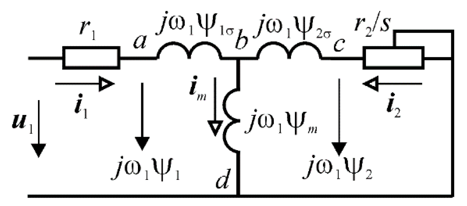
For scalar and vector controls, the initial, basic equations are drawn up according to the equivalent circuit of an IMD (
Figure 3) [
5,
8,
15]. Then, the voltages in individual sections of the circuit will be determined according to Equations (1)–(4) [
5,
8,
15].
where
—stator voltage;
—stator current;
and
—flux linkage of the rotor and stator, respectively;
—general flux linkage;
—magnetic field rotation speed;
and
—active resistance of the stator and rotor windings, respectively;
and
—leakage inductive reactance of the stator and rotor windings, respectively;
where
—projection of the rotor flux linkage on the
d-axis;
—rotor time constant;
—stator time constant taking into account the dissipation factor
; p—Laplace operator;
—inductive coupling of the stator and rotor winding;
—rotor rotation speed;
—dissipation factor;
and
—the coefficients of the electromagnetic coupling of the stator and rotor, respectively.
These equations contain the products of inductances and flux linkages, for example, L and for the frequencies of the stator and rotor currents and , both for constant values, which is impossible with frequency control. Thus, the equations that are the basis for the vector control of an IMD are valid only at a constant frequency of the stator voltage (as well as stator and rotor currents) and the harmonic composition of flux linkages, that is, in the complete absence of higher harmonics in the motor currents.
It is quite simple to show that the last assumption does not hold, in almost any IMD, in any operating mode, and with any control algorithm. For this, the authors conducted tests, the content and results of which are described in several articles [
7,
9]. It is more difficult to estimate the error of such a formulation of the equations and the influence of this error on the control efficiency.
The derivation of the vector control equations contains many simplifications and assumptions, some of which are mentioned in this work. The studies carried out suggest that the real cost of these inaccuracies is the ineffective control of IMD.
It is also obvious that any engineering analysis and derivation of control algorithms would be extremely difficult without these simplifications. Moreover, most experts consider them inevitable. Let us consider the main problems, in our opinion, of describing IMD.
1. Sinusoidal currents of the stator and rotor of Induction motors with frequency control.
The sinusoidality of the rotor and stator currents is a fundamental assumption, without which practically the entire mathematical apparatus for describing alternating current electric motors would not be possible. This assumption is especially important for vector control.
Vector control tries to control the torque as the product of flux linkage projections on the longitudinal and transverse axes [
5,
8,
10,
15]. Since the form of the flux linkage equations is invariant to the choice of the coordinate system, then in an arbitrary coordinate system (
mn), the moment equation will have the form:
It does not consider that the flux linkages have higher harmonics, which, in principle, are not controlled. The selected fundamental harmonics of the flux linkages are controlled very indirectly, according to a convenient coordinate system, which is calculated using simplified equations of the “flux link identifier” in [
5,
8,
10,
15]:
where
—dissipation factor;
and
—the coefficients of the electromagnetic coupling of the stator and rotor, respectively.
These equations, presented in a fixed (stationary) coordinate system (
αβ), will correspond to a very simplified structural diagram (
Figure 4).
It is very difficult to expect precision and efficiency from such control. It is difficult to prove this complexity theoretically and quantify it, but this is very significant.
Unlike motors with an active magnetic flux, in which one of the factors in Equation (5) determining the torque is constant, and the higher harmonics of another factor in Equation (6) lead to higher harmonics of the torque, which does not affect the operation of the drive, in an induction motor, both magnetic fluxes are periodic, stator and rotor. Consequently, in the mechanical torque, even from the multiplication of high-frequency components, low-frequency components can be obtained that are completely uncontrolled and uncontrollable. If they form a symmetrical system due to the three phases of the motor, they will only cause heating of the windings; in the worst case, the torque will be uncontrollable.
Even though all FC manufacturers actively offer sets of filters and chokes for frequency converters to filter external interference and the high-frequency interference created by the IMD, the theory of IMD control allows all the harmonics of the rotor and stator currents, except for the main working one to be neglected. The working harmonic of the stator current with a frequency from 0 to 1000 Hz (in most FCs) can also suppress interference. Still, filters are offered for a much larger range of interferences. In contrast, when describing the processes of controlling the torque and rotation speed in motors, these harmonics are disregarded.
It is quite easy to check the presence of higher harmonics in the motor currents. These phenomena are most evident in the rotor currents. The experiments are described in detail in [
19,
21,
22]. They show that the rotor currents in static modes also contain significant harmonics that differ from the fundamental. There are reasons for their appearance in drives, such as power elements in the inverter operating in a pulsed mode and the variable frequency of the stator voltage.
4. The Imperfection of Vector Control Algorithms
Most often, considering the dynamics of IMD, it is vector control that is analyzed, considering that scalar, even corrected, is just a reliable, simple, but inaccurate and slow control, which, in principle, cannot be used in relatively accurate and fast-acting systems. In this case, the problems of vector control are recognized but are considered to be smaller. The complexity of vector algorithms (the simplest) is superior to scalar control.
Usually, vector control problems [
3,
11,
23,
24,
25] are reduced to a mismatch between the motor model in the control unit and the real parameters of the electric motor, which can vary during operation, adding changes in the load torque and other unknown features to this series. Numerous “observers” have been proposed in scientific papers to solve this problem. It is not easy to answer unambiguously how effective they are, but not a single significant manufacturer of FCs has introduced them into circuits and algorithms, bearing in mind that vector control itself is already a modal control method. That is, it relies on numerous models calculated with varying degrees of accuracy on many unmeasured coordinates.
The purpose of vector control is to reduce torque formation to dependencies close to the dependencies typical for linear control systems (with DC motors). For this, many calculations are performed in the control unit of the FC for nonlinear coordinate transformations and analogs of complex functions that form real processes in the electric motor (flux linkages, for example).
In this case, a lot of inevitable simplifications are used [
8]; several assumptions are made for the coordinate decoupling unit, which calculates the projection of the stator voltage on the
d and
q axes: “The coordinate decoupling unit can be built on the basis of the equations of the voltage-controlled IM model. We can put
= 0 and
=
ω in them...”.
An analysis of these equations of a generalized AC electric motor, assumptions, and conclusions of control algorithms led to the following questions:
1. How significant are the errors with which the dynamics in IMD are described by a simple consideration of changes in the stator voltage frequency when using mathematical equations that are accurate only at a constant frequency?
2. To what extent is it possible to identify a signal with variable frequencies by a vector with variable parameters?
Let us recall some theoretical propositions. A vector is a mathematical element that has magnitude and direction, and it can describe a sinusoidal process or a signal of only a certain frequency and amplitude. Each such frequency and, accordingly, each stator voltage vector can be assigned its own vector diagram, and if, identifying an IMD with frequency control, we “simply” in the equations obtained for a constant frequency of the stator voltage, put a variable frequency (also with equation simplifications), this is equivalent to representing the process in the motor to changes in vector diagrams or equivalent circuits. Of all the variety of such schemes and diagrams, our description considers only those states in which currents and voltages are sinusoidal. Separate “spatial” formations are artificially selected from the complex space of such states and are not related to each other. They do not describe intermediate states or transitions between them.
The equations connecting vector quantities cannot consider the appearance of higher harmonics in the signals of an induction motor and their influence on the operation of an electric drive. They cannot consider the dynamics of the transition from one structure to another.
As a result, we get a mathematical description of the processes, only in certain modes, close to reality. Such modes can drive acceleration with constant dynamic torque. In this case, the assumptions (for example, about the constancy of the rotary magnetic flux) are quite valid. But in other modes (for example, parrying load surges, which begin with the rotor’s braking and processes in the rotor), the errors become extremely large. What is the error of replacing dynamic processes with sets of static positions? This is an almost philosophical question and brings to mind Zeno, who argued with logical aporias that a continuous process and a sequence of static positions coinciding with a continuous one at specific times are not the same things. Despite that, engineering problems and methods for their solution are far from philosophical constructions and disputes that took place two and a half thousand years ago. The question arises as to the cost of this neglect. The provisions presented in this article and their analysis allow us to assert:
The cost of these assumptions is the inaccuracy and inefficiency of the vector control of IMD.
On the proposed paradigm in engineering analysis.
It is obvious from the above equations that the method based on the assumption of the sinusoidality of the motor currents has a significant error, and this raises many questions. Can we call a vector a quantity that continuously changes both amplitude and frequency? What is the phase shift of such a signal?
Let us look at the simplest example. If the stator voltage changes frequency, then it is usually described by the vector (with the initial phase equal to zero
φu = 0):
This corresponds to function from time to time:
But with a variable frequency, it should look like this:
How to estimate the error in vector interpretation of variable frequency voltage? The problem can be formulated as follows:
1. There is a nonlinear equation that does not have an exact solution for
, the arbitrary functions
.
2. When “freezing”,
are constant values and the solution to the equation is trivial:
3. When “defrosting”
, you can get the function
X as an inaccurate and even erroneous solution for the variable function
φ of time. This is exactly what is done when deriving vector control in [
5,
8,
10,
15]. Another approach is possible:
4. If you “freeze” the function, you can get the Laplace transform for the original equation:
And find a solution in the form of the same transformation:
5. After defrosting the function, the solution turns into a family of solutions, a family of transfer functions:
Will this family of solutions, according to Laplace: (13) and (15) be closer to the real process (which is described by Equation (11) and which does not have an exact solution) than the defrosted function (12)?
In one case it is a function, and in the other it is a family of transformations, which is evidence that the accuracy of these solutions cannot be the same. In the first case of an incorrect solution, the nonlinearity of the function is simply “forgotten.” In the second, it transforms into the multidimensionality of Laplace transformations and transfer functions. Remaining an incorrect solution, the qualitative features of the sought functions are preserved, and this must be used correctly.
Since this problem belongs to mathematics, the following paradigm is proposed for the engineering solution of the problem.
1. There is vector control, built on simplifications of the vector equations of an induction motor, described in detail in [
5,
8,
10,
15].
2. A different identification of the dynamics of the processes in the engine and the correction method from this interpretation are proposed.
3. Compare the efficiency of a vector control drive and the efficiency of a drive corrected by a method based on a different interpretation of the IMD. This comparison is made using experimental methods, and the result will confirm the lower error of the method.
5. Solutions
An induction motor can be described by differential equations, albeit with substantially nonlinear components like any electromechanical system. When some variables are “frozen,” these equations can be linearized. Then Laplace transformations of the equations can be carried out, and the transfer functions of the drive links, for example, the links of the formation of the moment [
14,
21,
31], can be obtained. Changes in the “frozen” coefficients and variables turn these functions into families of functions. Together they can form families of transfer functions and frequency characteristics. Unlike the vector equation used by traditional methods for describing IMD, this family will exist for all stator voltage frequencies and accurately describing the processes with small changes in the “frozen” parameters. That is, in contrast to the “discontinuous” space of vector states of a linear object, we get a “filled” continuous, albeit not a fully accurate description of the processes in an IMD.
In [
8,
9,
10] for the analysis of processes in IMD with frequency control, nonlinear transfer functions are proposed that connect the torque (
m), relative slip (
β), and engine parameters (
T2 is the transient time constant;
Mk and
Sk are the critical torque and critical slip, depending on the frequency
ω1):
The transfer function resulting from this dependence connects the absolute slip and the mechanical moment developed by the IMD and the structural diagram (
Figure 5):
where
ω1 is the frequency of the stator voltage, and
Jd is the moment of inertia of the motor.
With frequency control, Mk and Sk change, and these changes show how W(p) changes with a particular control method. Strictly speaking, this transfer function is also a simplified version of the description of the nonlinear dynamics of an IMD. Variable parameters depending on and are present in a “frozen” form. It is impossible to obtain such an expression after Laplace transformations (and the transfer function results from this very operation). But this formulation of the nonlinear transfer function encompasses the entire state space, describing processes in electric motors with any spectrum of signals of currents and voltages. That is, the complex state space, described by an unsolvable nonlinear equation, is identified by a nonlinear space, covered by a nonlinear transfer function that exists for any variables, and the space is divided into an infinite number of “slices” for any value describing the dynamic process in this slice. Since the transfer function Equation (15) is continuous, it can be argued that there are inverse Laplace transforms for signals obtained using this Equation. However, we cannot get the exact value of these transformations to assert the same in relation to the signals obtained from the vector equations because of their discontinuity.
As follows from Equation (16), families of frequency characteristics and transfer functions exist for any value of the frequency of the stator voltage and other signals; moreover, these spectra may not coincide due to the significant nonlinearity of the elements of the frequency electric drive. These are the differences in the interpretation of an IMD by the transfer function from vector equations and the difference that gives an advantage to this method.
The corrections synthesized by a family of transfer functions or frequency characteristics should also be sufficiently accurate and effective.
From this transfer function, methods of correction and the evaluation of the effectiveness of the control method follow, according to the magnitude of the absolute slip required to create the torque
Then the equivalent transfer function takes the form
The block diagram for this case is shown in
Figure 6.
These methods are described in [
9]. This dynamic positive feedback (DPF) on the motor torque allows you to adjust the family of transfer functions of the torque generator in an IMD.
6. Experimental Results
When introducing positive feedback with special dynamic links with a transfer function close to Equation (13) into the correction circuits of scalar control, it is possible to obtain a stable IMD with significant advantages over open-loop vector and scalar controls and over closed vector control in terms of speed and accuracy maintaining the speed. This is confirmed by the experiments described in [
14,
21,
31], and one of the examples of which is shown in
Figure 6. The advantages in terms of transient time and dynamic dips in the speed of a drive with DPF are obvious in experiments on parrying torque loads, which is the most difficult operating mode for a drive that maintains rotation speed. The processes are as follows (
Figure 7).
The main characteristics of the processes: Transient time, 1.5 s in a circuit with a PI vector control regulator and 0.08 s in a drive with DPF; dynamic speed error, 12 rps for PI controller and 6 rps in a circuit with DPF. Stator static current under load is 1.8 A in the drive with PI regulator and 1 A with DPF.
The method for evaluating the effectiveness of methods for controlling IMD by the rotor current frequency, which is rigidly associated with slip, is presented in [
13,
14,
16]. Experiments, described in detail in [
14,
21,
31], have shown that to create the same torque in the motor, corrected by cross-coupling by the torque or by its close analog (the effective value of the stator current), the frequency of the rotor current and, accordingly, the slip is three times less than in a drive with vector control, with a PI regulator (3.2 Hz vs. 9.7 Hz) see
Figure 8 and
Figure 9.
Pay attention to the amplitudes of the rotor currents. In the IMD with DPF, it is 1 A (
Figure 9a), and in the IMD with vector control, it is 2 A (
Figure 8a). As a result, the amplitude and hence the RMS (root mean square) of the rotor current is two times less at close values of the load.
7. Results Discussion
These experiments showed two main results:
(1) The signal spectra of the motor currents with frequency control are nonlinear;
(2) The processes themselves are non-sinusoidal, practically under any control.
For a drive with vector control with a PI speed controller, the frequency of rotor currents is the highest; that is, to create the same torque in such a drive, the maximum absolute slip of all the considered control schemes is required.
This was also confirmed by numerous experiments and simulations [
7,
8,
24,
25] of various operating modes of the drive and its standard models. The results are described in detail in articles and reports at scientific conferences [
14,
21,
31].
Almost all works and studies devoted to the frequency control of IMD are based on the vector equations of a generalized alternating current machine and, in particular, an induction motor.
The vector equations [
5,
8,
10] when outputting control signals in an arbitrary coordinate system (for example, along the
d and
q axes) fall under significant simplifications, which are allowed only in limited operating modes (most often when the drive is accelerating with a minimum or constant load).
Significant inaccuracies in correction systems will be characteristic of transients associated with dynamic changes in the frequency and amplitude of the stator voltage. These inaccuracies are determined by the fundamental limitation of the vector equations, which are valid only for a constant stator voltage frequency. Thus, vector equations are an attempt to represent continuous processes of regulation by a set of variable static states, “broken” among themselves. That is why descriptions of transients, especially complex and their correction by vector equations, are ineffective.
We can recall the famous Zeno’s paradoxes, which for two thousand years treated philosophers (starting with the great Aristotle) precisely because he made them see the absurdity in the identity of continuous movement and a set of positions of rest (the strongest and most famous of them—the paradox about “Achilles and the tortoise” and paradox about “an arrow in flight”).
The transfer function that identifies the IMD is inaccurate but still a function that exists at variable frequencies of the stator voltage. And it allows us to both describe the dynamics and choose the correction more accurately.
Following the paradigm proposed above, the experimental results allow us to assert that the increased efficiency of an IMD with positive feedback analogous to the torque (the active component of the stator current) with a dynamic link is the result of a more accurate mathematical interpretation of the electric motor and the correction derived from this interpretation.
In other words, the nonlinear transfer function obtained for variable frequency and slip, although inaccurate, is more accurate than vector equations when describing and correcting processes inside each of the many nonlinear transfer functions describing the formation of torque in IMD with frequency control.
8. Conclusions
The experiments confirm the assumption that for a system with signals with variable frequencies, amplitudes, and phases, the representation of the system signals by harmonic variables carries a greater error than the representation of the elements of this system by nonlinear transfer functions with “frozen” parameters. The entire sequence of studies confirmed this, the identification of a complex object, a technique for evaluating the slip efficiency necessary to create torque, determined by the frequency of the rotor current and correction by cross-links, primarily by positive dynamic coupling of the effective value of the stator current, which has shown its effectiveness.
If we analyze vector equations as a technique for describing the processes in IMD with frequency control, it should be noted that these equations relate only to static states, and do not consider the possible inharmonic composition of signals. Therefore, only separate isolated states are considered in the “state space” of the electric motor, not interconnected by “continuous” surfaces, identifying possible signals of the variables of the electric motor.
A nonlinear transfer function, the input of which is absolute slip, depending on the frequency of the stator voltage and load, allows you to obtain an effective way of correcting the drive and ensure the accuracy of maintaining speed during load surges. That is, in the most difficult operating mode for an electric drive. Experiments on such an assessment were very clear, as were the modeling processes in IMD. According to Laplace, the linearization of transfer functions has smaller errors than the direct linearization of nonlinear differential equations.
Experiments have shown that in the motor mode, the parrying of the same load in the IMD with DPF occurs at three times less absolute slip and half the rotor currents (the stator currents are almost the same).
There is practical value for several drives and industries, including wind turbines and transport. Based on this transfer function, correction methods were obtained. A positive cross-connection for the motor torque (in a particular implementation, this connection is for the active component of the stator current) with dynamic links ensures stability. This correction provides significantly better results in load parrying than vector and scalar control, which was confirmed by experiments and simulations.
The next step in the research is optimizing the generator modes of the IMD, which are very important for drives of electric vehicles and wind turbines. In transport, improving the efficiency of braking energy recuperation will provide many advantages: reduced energy consumption while driving, efficient use of battery energy, etc.
In wind energy, generation optimization will improve the overall efficiency of powerful installations, usually dual-powered machines (AC electric machines, which are often also described by vector equations).


