
MVDC Railway Traction Power Systems; State-of-the Art, Opportunities, and Challenges


Abstract
:1. Introduction
2. State-of-the-Art MVDC TPS
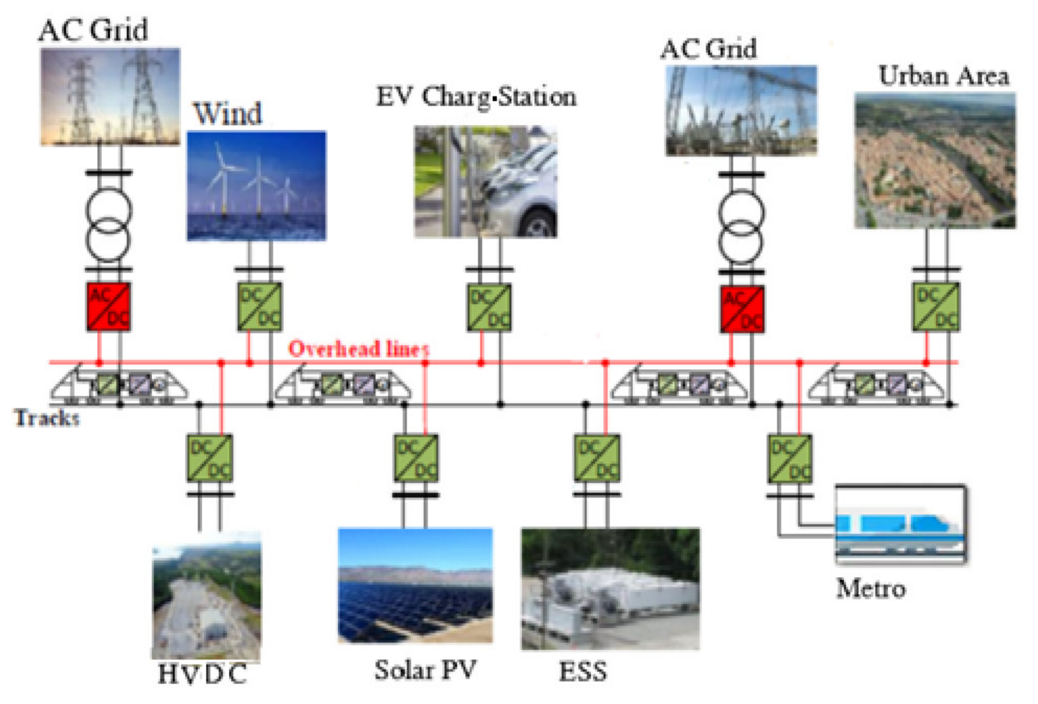
2.1. Overview of the MVDC TPS
2.2. MVDC TPS as an Enhanced DC TPS
2.3. MVDC TPS Control
3. Key Opportunities and Challenges
3.1. Component Level
3.1.1. Wide-Bandgap (WBG) Semiconductors
3.1.2. Medium-Frequency Transformers (MFTs)
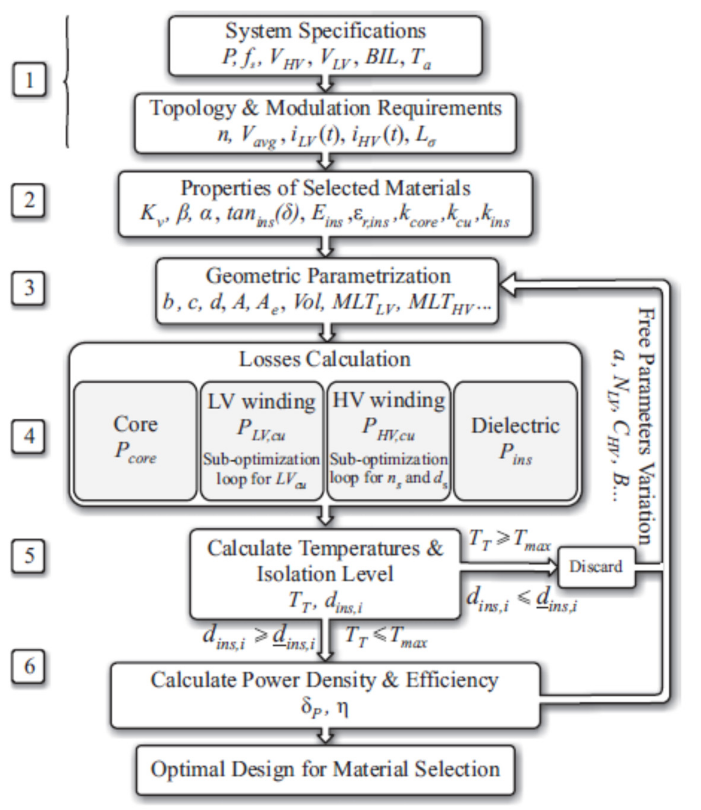
- The transformer system’s level characteristics are defined to a circuit calculator.
- Conductor, isolation, and core material properties are introduced.
- The geometry of the transformer parts is parameterized with respect to the free variables that are varied during the designing process in order to realize an optimal design.
- The core, windings, and insulation losses are calculated considering high-frequency (HF) effects.
- The temperature of the components is estimated using thermal models, and the isolation level reached is calculated. If both parameters meet the requirements, the values are stored and another set of parameters is selected for the next design process.
- Once all of the combinations of free parameters are tested, the optimal set of free parameters for the given optimization process (i.e., efficiency or power density) can be extracted. A new optimization process can be initiated with a different selection of core materials for comparison.
3.2. Converter Level
3.2.1. Voltage-Source Converters (VSC)
3.2.2. Power Electronic Transformers (PETs)
3.3. System Level
4. Conclusions
Author Contributions
Funding
Acknowledgments
Conflicts of Interest
References
- Bhargava, B. Railway electrification systems and configurations. In Proceedings of the 1999 IEEE Power Engineering Society Summer Meeting. Conference Proceedings (Cat. No.99CH36364), Edmonton, AB, Canada, 18–22 July 1999; Volume 1, pp. 445–450. [Google Scholar] [CrossRef]
- Brenna, M.; Foiadelli, F.; Zaninelli, D. Electrical Railway Transportation Systems; John Wiley & Sons, Inc.: Hoboken, NJ, USA, 2018. [Google Scholar]
- ABB. ABB, Powering the World’s High-Speed Rail Networks. Available online: https://library.e.abb.com/public/3e14a09a05a47c17c12578f7005e8c8d/ABB-powering-%20the-worlds-high-speed-rail-network.pdf (accessed on 25 May 2021).
- Laousse, D.; Paris, C.B.; Caron, H.; Courtois, C.; Denis, S. Direct current—A future under which conditions? Elektr. Bahnen 2016, 114, 260–275. [Google Scholar]
- Steimel, A. Under Europe’s Incompatible Catenary Voltages a Review of Multi-System Traction Technology. In Proceedings of the 2012 Electrical Systems for Aircraft, Railway and Ship Propulsion, Bologna, Italy, 16–18 October 2012; Institute of Electrical and Electronics Engineers (IEEE): New York, NY, USA, 2012. [Google Scholar]
- Hinz, A.; Stieneker, M.; de Doncker, R.W. Impact and opportunities of medium-voltage DC grids in urban railway systems. In Proceedings of the 2016 18th European Conference on Power Electronics and Applications (EPE’16 ECCE Europe), Karlsruhe, Germany, 5–9 September 2016; Institute of Electrical and Electronics Engineers (IEEE): New York, NY, USA, 2016; pp. 1–10. [Google Scholar]
- Gomez-Exposito, A.; Mauricio, J.M.; Maza-Ortega, J.M. VSC-Based MVDC Railway Electrification System. IEEE Trans. Power Deliv. 2013, 29, 422–431. [Google Scholar] [CrossRef]
- Verdicchio, A.; Ladoux, P.; Caron, H.; Courtois, C. New Medium-Voltage DC Railway Electrification System. IEEE Trans. Transp. Electrif. 2018, 4, 591–604. [Google Scholar] [CrossRef]
- Verdicchio, A.; Ladoux, P.; Caron, H.; Sanchez, S. Future DC Railway Electrification System—Go for 9 kV. In Proceedings of the 2018 IEEE International Conference on Electrical Systems for Aircraft, Railway, Ship Propulsion and Road Vehicles & International Transportation Electrification Conference (ESARS-ITEC), Nottingham, UK,, 7–9 November 2018; Institute of Electrical and Electronics Engineers (IEEE): New York, NY, USA, 2018; pp. 1–5. [Google Scholar]
- Yang, X.; Hu, H.; Ge, Y.; Aatif, S.; He, Z.; Gao, S.; Salman, A. An Improved Droop Control Strategy for VSC-Based MVDC Traction Power Supply System. IEEE Trans. Ind. Appl. 2018, 54, 5173–5186. [Google Scholar] [CrossRef]
- Aatif, S.; Hu, H.; Yang, X.; Ge, Y.; He, Z.; Gao, S. Adaptive droop control for better current-sharing in VSC-based MVDC railway electrification system. J. Mod. Power Syst. Clean Energy 2019, 7, 962–974. [Google Scholar] [CrossRef] [Green Version]
- Arboleya, P.; Mayet, C.; Mohamed, B.; Aguado, J.A.; de la Torre, S. A review of railway feeding infrastructures: Mathematical models for planning and operation. eTransportation 2020, 5, 100063. [Google Scholar] [CrossRef]
- Steele, H.; Roberts, C.; Hillmansen, S. Railway smart grids: Drivers, benefits and challenges. Proc. Inst. Mech. Eng. Part F: J. Rail Rapid Transit 2019, 233, 526–536. [Google Scholar] [CrossRef]
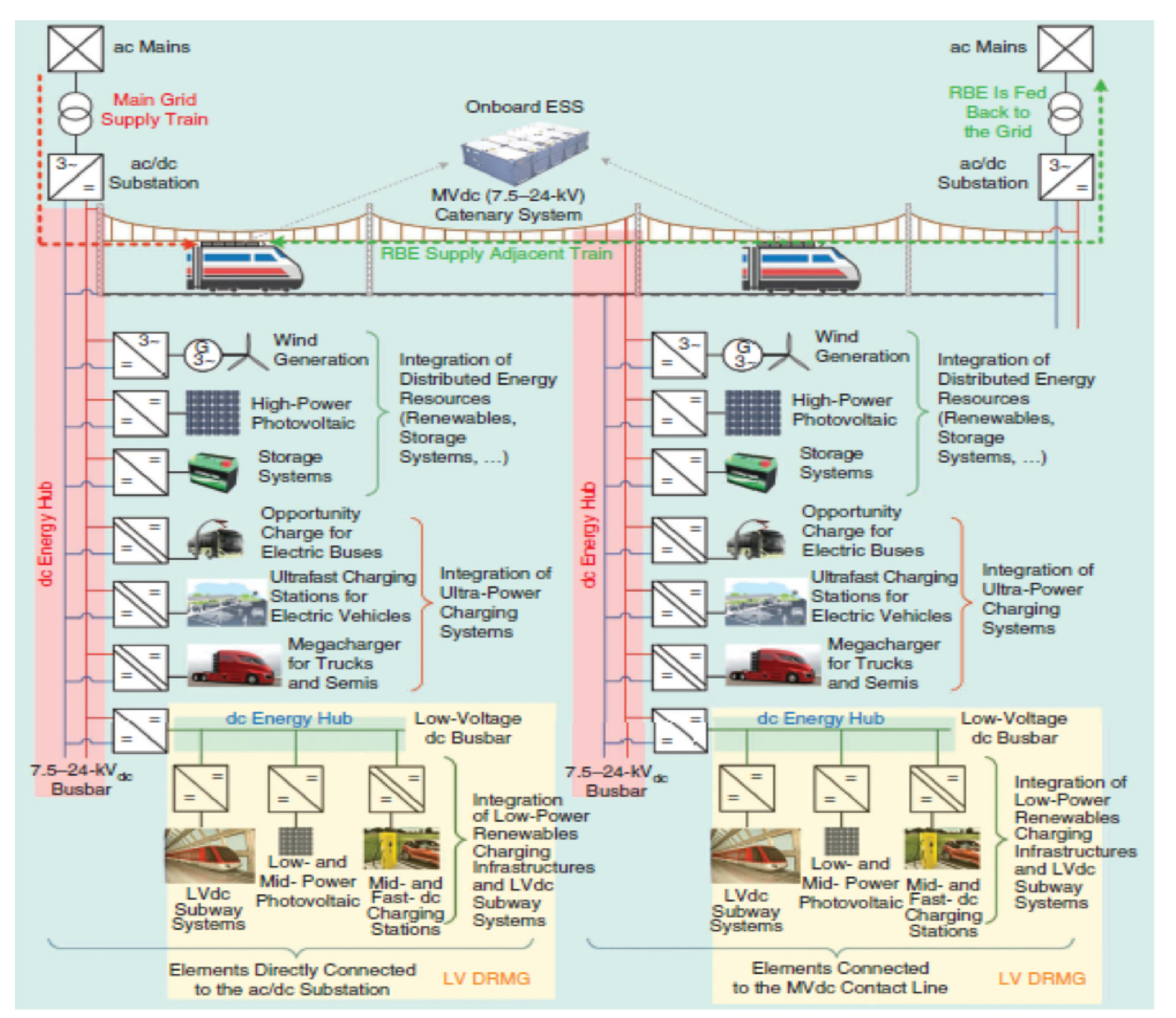
- Brenna, M.; Foiadelli, F.; Kaleybar, H.J. The Evolution of Railway Power Supply Systems Toward Smart Microgrids: The concept of the energy hub and integration of distributed energy resources. IEEE Electrif. Mag. 2020, 8, 12–23. [Google Scholar] [CrossRef]
- Leander, P.; Ostlund, S. A Concept for an HVDC Traction System. In Proceedings of the International Conference on Main Line Railway Electrification 1989, York, UK, 25–28 September 1989; IET: London, UK, 1989. [Google Scholar]
- Abrahamsson, L.; Kjellqvist, T.; Ostlund, S. High-voltage DC-feeder solution for electric railways. IET Power Electron. 2012, 5, 1776–1784. [Google Scholar] [CrossRef] [Green Version]
- Stieneker, M.; Mortimer, B.J.; Hinz, A.; Muller-Hellmann, A.; de Doncker, R.W. MVDC Distribution Grids for Electric Vehicle Fast-Charging Infrastructure. In Proceedings of the International Power Electronics Conference, Niigata, Japan, 20–24 May 2018; Institute of Electrical and Electronics Engineers (IEEE): New York, NY, USA, 2018. [Google Scholar]
- Stieneker, M.; Doncker, R.W.D. Medium-voltage DC distribution grids in urban areas. In Proceedings of the IEEE 7th International Symposium on Power Electronics for Distributed Generation Systems (PEDG), Vancouver, BC, Canada, 27–30 June 2016; Institute of Electrical and Electronics Engineers (IEEE): New York, NY, USA, 2016. [Google Scholar]
- Aatif, S.; Yang, X.; Hu, H.; Maharjan, S.K.; He, Z. Integration of PV and Battery Storage for Catenary Voltage Regulation and Stray Current Mitigation in MVDC Railways. J. Mod. Power Syst. Clean Energy 2021, 9, 585–594. [Google Scholar] [CrossRef]
- Serrano-Jiménez, D.; Abrahamsson, L.; Castaño-Solís, S.; Sanz-Feito, J. Electrical railway power supply systems: Current situation and future trends. Int. J. Electr. Power Energy Syst. 2017, 92, 181–192. [Google Scholar] [CrossRef]
- Shigeeda, H.; Morimoto, H.; Ito, K.; Fujii, T.; Morishima, N. Feeding-loss Reduction by Higher-voltage DC Railway Feeding System with DC-to-DC Converter. In Proceedings of the 2018 International Power Electronics Conference, Niigata, Japan, 20–24 May 2018; Institute of Electrical and Electronics Engineers (IEEE): New York, NY, USA, 2018. [Google Scholar]
- Ferencz, I.; Petreus, D.; Tricoli, P. Converter Topologies for MVDC Traction Transformers. In Proceedings of the 2020 IEEE 26th International Symposium for Design and Technology in Electronic Packaging (SIITME), Pitesti, Romania, 21–24 October 2020; Institute of Electrical and Electronics Engineers (IEEE): New York, NY, USA, 2020; pp. 362–367. [Google Scholar]
- Huber, J.E.; Kolar, J.W. Solid-State Transformers: On the Origins and Evolution of Key Concepts. IEEE Ind. Electron. Mag. 2016, 10, 19–28. [Google Scholar] [CrossRef]
- Huber, J.E.; Kolar, J.W. Applicability of Solid-State Transformers in Today’s and Future Distribution Grids. IEEE Trans. Smart Grid 2019, 10, 317–326. [Google Scholar] [CrossRef]
- Giannakis, A.; Peftitsis, D. MVDC Distribution Grids and Potential Applications: Future Trends and Protection Challenges. In Proceedings of the 20th European Conference on Power Electronics and Applications (EPE’18 ECCE Europe), Riga, Latvia, 17–21 September 2018; Institute of Electrical and Electronics Engineers (IEEE): New York, NY, USA, 2018. [Google Scholar]
- Pei, X.; Cwikowski, O.; Rodriguez, D.S.V.; Barnes, M.; Smith, A.; Shuttleworth, R. A review of technologies for MVDC circuit breakers. In Proceedings of the IECON 2016—42nd Annual Conference of the IEEE Industrial Electronics Society, Florence, Italy, 23–26 October 2016; Institute of Electrical and Electronics Engineers (IEEE): New York, NY, USA, 2016; pp. 3799–3805. [Google Scholar]
- Siemens. MVDC Plus—Managing the Future Grid; Siemens AG: Munich, Germany, 2017; p. 8. [Google Scholar]
- Zhu, R.; Liang, T.; Dinavahi, V.; Liang, G. Wideband Modeling of Power SiC mosfet Module and Conducted EMI Prediction of MVDC Railway Electrification System. IEEE Trans. Electromagn. Compat. 2020, 62, 2621–2633. [Google Scholar] [CrossRef]
- Ghaviha, N.; Campillo, J.; Bohlin, M.; Dahlquist, E. Review of Application of Energy Storage Devices in Railway Transportation. Energy Procedia 2017, 105, 4561–4568. [Google Scholar] [CrossRef]
- Khodaparastan, M.; Mohamed, A.A.; Brandauer, W. Recuperation of Regenerative Braking Energy in Electric Rail Transit Systems. IEEE Trans. Intell. Transp. Syst. 2019, 20, 2831–2847. [Google Scholar] [CrossRef] [Green Version]
- Sparacino, A.R.; Grainger, B.M.; Kerestes, R.J.; Reed, G.F. Design and simulation of a DC electric vehicle charging station connected to a MVDC infrastructure. In Proceedings of the 2012 IEEE Energy Conversion Congress and Exposition (ECCE), Raleigh, NC, USA, 15–20 September 2012; Institute of Electrical and Electronics Engineers (IEEE): New York, NY, USA, 2012; pp. 1168–1175. [Google Scholar]
- Wang, Y.; Zheng, Z.; Li, Y. DAB-based PET in MVDC traction and shipboard applications with distribution and redundant control. J. Eng. 2018, 20, 3209–3213. [Google Scholar]
- Feng, J.; Chu, W.; Zhang, Z.; Zhu, Z. Power Electronic Transformer-Based Railway Traction Systems: Challenges and Opportunities. IEEE J. Emerg. Sel. Top. Power Electron. 2017, 5, 1237–1253. [Google Scholar] [CrossRef]
- Hammerstrom, D.J. AC Versus DC Distribution Systems, Did We Get it Right? In Proceedings of the 2007 IEEE Power Engineering Society General Meeting, Tampa, FL, USA, 24–28 June 2007; Institute of Electrical and Electronics Engineers (IEEE): New York, NY, USA, 2007. [Google Scholar]
- Sannino, A.; Postiglione, G.; Bollen, M. Feasibility of a DC network for commercial facilities. IEEE Trans. Ind. Appl. 2003, 39, 1499–1507. [Google Scholar] [CrossRef]
- Nilsson, D.; Sannino, A. Efficiency analysis of low- and medium-voltage dc distribution systems. In Proceedings of the Eighth IEEE International Symposium on Spread Spectrum Techniques and Applications—Programme and Book of Abstracts (IEEE Cat. No.04TH8738), Denver, CO, USA, 6–10 June 2004; Institute of Electrical and Electronics Engineers (IEEE): New York, NY, USA, 2005; Volume 2, pp. 2315–2321. [Google Scholar]
- Khayyam, S.; Ponci, F.; Goikoetxea, J.; Recagno, V.; Bagliano, V.; Monti, A. Railway Energy Management System: Centralized–Decentralized Automation Architecture. IEEE Trans. Smart Grid 2015, 7, 1164–1175. [Google Scholar] [CrossRef]
- Gran, R.J. Numerical Computing with Simulink, Volume I: Creating Simulations; Society for Industrial and Applied Mathematics: Philadelphia, PA, USA, 2007. [Google Scholar]
- Simiyu, P.; Xin, A.; Bitew, G.T.; Shahzad, M.; Kunyu, W.; Tuan, L.K. Review of the DC voltage coordinated control strategies for multi-terminal VSC-MVDC distribution network. J. Eng. 2019, 2019, 1462–1468. [Google Scholar] [CrossRef]
- Gao, F.; Bozhko, S.; Asher, G.; Wheeler, P.; Patel, C. An Improved Voltage Compensation Approach in A Droop-Controlled DC Power System for the More Electric Aircraft. IEEE Trans. Power Electron. 2015, 31, 1. [Google Scholar] [CrossRef]
- Dragicevic, T.; Lu, X.; Vasquez, J.C.; Guerrero, J.M. DC Microgrids–Part I: A Review of Control Strategies and Stabilization Techniques. IEEE Trans. Power Electron. 2015, 31, 4876–4891. [Google Scholar] [CrossRef] [Green Version]
- Rouzbehi, K.; Miranian, A.; Luna, A.; Rodriguez, P. DC Voltage Control and Power Sharing in Multiterminal DC Grids Based on Optimal DC Power Flow and Voltage-Droop Strategy. IEEE J. Emerg. Sel. Top. Power Electron. 2014, 2, 1171–1180. [Google Scholar] [CrossRef]
- Gavriluta, C.; Candela, I.; Luna, A.; Gomez-Exposito, A.; Rodriguez, P. Hierarchical Control of HV-MTDC Systems With Droop-Based Primary and OPF-Based Secondary. IEEE Trans. Smart Grid 2014, 6, 1502–1510. [Google Scholar] [CrossRef]
- Simiyu, P.; Xin, A.; Wang, K.; Adwek, G.; Salman, S. Multiterminal Medium Voltage DC Distribution Network Hierarchical Control. Electronics 2020, 9, 506. [Google Scholar] [CrossRef] [Green Version]
- Hao, F.; Zhang, G.; Chen, J.; Liu, Z.; Xu, D.; Wang, Y. Optimal Voltage Regulation and Power Sharing in Traction Power Systems with Reversible Converters. IEEE Trans. Power Syst. 2020, 35, 2726–2735. [Google Scholar] [CrossRef]
- Khayyam, S.; Berr, N.; Razik, L.; Fleck, M.; Ponci, F.; Monti, A. Railway System Energy Management Optimization Demonstrated at Offline and Online Case Studies. IEEE Trans. Intell. Transp. Syst. 2018, 19, 3570–3583. [Google Scholar] [CrossRef]
- Razik, L.; Berr, N.; Khayyam, S.; Ponci, F.; Monti, A.; Khayyamim, S. REM-S–Railway Energy Management in Real Rail Operation. IEEE Trans. Veh. Technol. 2018, 68, 1266–1277. [Google Scholar] [CrossRef]
- Wang, F.; Zhang, Z.; Jones, E.A. Characterization of Wide Bandgap Power Semiconductor Devices; IET: London, UK, 2018. [Google Scholar]
- Das, S.; Marlino, L.D.; Armstrong, K.O. Wide Bandgap Semiconductor Opportunities in Power Electronics. Technical Report ORNL/TM-2017/702. 2017. Available online: https://www.osti.gov/biblio/1415915/ (accessed on 30 May 2021).
- Millan, J.; Godignon, P.; Perpiñà, X.; Perez-Tomas, A.; Rebollo, J. A Survey of Wide Bandgap Power Semiconductor Devices. IEEE Trans. Power Electron. 2014, 29, 2155–2163. [Google Scholar] [CrossRef]
- Armstrong, K.O.; Das, S.; Cresko, J. Wide bandgap semiconductor opportunities in power electronics. In Proceedings of the IEEE 4th Workshop on Wide Bandgap Power Devices and Applications (WiPDA), Fayetteville, AR, USA, 7–9 November 2016; Institute of Electrical and Electronics Engineers (IEEE): New York, NY, USA, 2016. [Google Scholar]
- Chow, T.P. Wide bandgap semiconductor power devices for energy efficient systems. In Proceedings of the 2015 IEEE 3rd Workshop on Wide Bandgap Power Devices and Applications (WiPDA), Blacksburg, VA, USA, 2–4 November 2015; Institute of Electrical and Electronics Engineers (IEEE): New York, NY, USA, 2015; pp. 402–405. [Google Scholar]
- Das, M.K.; Capell, C.; Grider, D.E.; Leslie, S.; Ostop, J.; Raju, R.; Schutten, M.; Nasadoski, J.; Hefner, A. 10 kV, 120 A SiC half H-bridge power MOSFET modules suitable for high frequency, medium voltage applications. In Proceedings of the 2011 IEEE Energy Conversion Congress and Exposition, Phoenix, AZ, USA, 17–22 September 2011; Institute of Electrical and Electronics Engineers (IEEE): New York, NY, USA, 2011; pp. 2689–2692. [Google Scholar]
- Hamada, K.; Hino, S.; Miura, N.; Watanabe, H.; Nakata, S.; Suekawa, E.; Ebiike, Y.; Imaizumi, M.; Umezaki, I.; Yamakawa, S. 3.3 kV/1500 A power modules for the world’s first all-SiC traction inverter. Jpn. J. Appl. Phys. 2015, 54, 4DP07. [Google Scholar] [CrossRef]
- Sato, K.; Kato, H.; Fukushima, T. Development of SiC Applied Traction System for Shinkansen High-speed Train. In Proceedings of the 2018 International Power Electronics Conference, Niigata, Japan, 20–24 May 2018; Institute of Electrical and Electronics Engineers (IEEE): New York, NY, USA, 2018. [Google Scholar]
- Huang, A.Q.; Wang, L.; Tian, Q.; Zhu, Q.; Chen, D.; Wensong, Y. Medium voltage solid state transformers based on 15 kV SiC MOSFET and JBS diode. In Proceedings of the IECON 2016—42nd Annual Conference of the IEEE Industrial Electronics Society, Florence Italy, 23–26 October 2016; Institute of Electrical and Electronics Engineers (IEEE): New York, NY, USA, 2016; pp. 6996–7002. [Google Scholar]
- Vechalapu, K.; Bhattacharya, S.; van Brunt, E.; Ryu, S.-H.; Grider, D.; Palmour, J.W. Comparative evaluation of 15 kV SiC MOSFET and 15 kV SiC IGBT for medium voltage converter under same dv/dt conditions. IEEE J. Emerg. Sel. Top. Power Electron. 2015, 5, 927–934. [Google Scholar] [CrossRef]
- Pala, V.; van Brunt, E.; Cheng, L.; Oloughlin, M.J.; Richmond, J.; Burk, A.; Allen, S.T.; Grider, D.; Palmour, J.W.; Scozzie, C.J. 10 kV and 15 kV silicon carbide power MOSFETs for next-generation energy conversion and transmission systems. In Proceedings of the 2014 IEEE Energy Conversion Congress and Exposition (ECCE), Pittsburgh, PA, USA, 14–18 September 2014; Institute of Electrical and Electronics Engineers (IEEE): New York, NY, USA, 2014; pp. 449–454. [Google Scholar]
- Hitachi. Hitachi IGBT Status List. 2021. Available online: https://www.hitachi-power-semiconductor-device.co.jp/en/products/igbt/pdf/ig13_eR3_2021_03.pdf (accessed on 20 May 2021).
- Toshiba. Comparison of SiC MOSFET and Si IGBT. 2020. Available online: https://toshiba.semicon-storage.com/info/docget.jsp?did=69799 (accessed on 20 May 2021).
- Yu, J.; Burgos, R.; Mehrabadi, N.R.; Boroyevich, D. DC fault current control of modular multilevel converter with SiC-based Power Electronics Building Blocks. In Proceedings of the IEEE Electric Ship Technologies Symposium (ESTS), Arlington, VA, USA, 14–17 August 2017; Institute of Electrical and Electronics Engineers (IEEE): New York, NY, USA, 2017. [Google Scholar]
- Agheb, E.; Hoidalen, H.K. Medium frequency high power transformers, state of art and challenges. In Proceedings of the 2012 International Conference on Renewable Energy Research and Applications (ICRERA), Nagasaki, Japan, 11–14 November 2012; Institute of Electrical and Electronics Engineers (IEEE): New York, NY, USA, 2012; pp. 1–6. [Google Scholar]
- Garcia, R.; Escobar-Mejia, A.; George, K.; Balda, J.C. Loss comparison of selected core magnetic materials operating at medium and high frequencies and different excitation voltages. In Proceedings of the 2014 IEEE 5th International Symposium on Power Electronics for Distributed Generation Systems (PEDG), Galway, Ireland, 24–27 June 2014; Institute of Electrical and Electronics Engineers (IEEE): New York, NY, USA, 2014; pp. 1–6. [Google Scholar]
- Ronanki, D.; Williamson, S.S. Evolution of Power Converter Topologies and Technical Considerations of Power Electronic Transformer-Based Rolling Stock Architectures. IEEE Trans. Transp. Electrif. 2017, 4, 211–219. [Google Scholar] [CrossRef]
- Ortiz, G.; Biela, J.; Kolar, J.W. Optimized design of medium frequency transformers with high isolation requirements. In Proceedings of the IECON 2010—36th Annual Conference on IEEE Industrial Electronics Society, Glendale, AZ, USA, 7–10 November 2010; Institute of Electrical and Electronics Engineers (IEEE): New York, NY, USA, 2010; pp. 631–638. [Google Scholar]
- Leibl, M.; Ortiz, G.; Kolar, J.W. Design and Experimental Analysis of a Medium-Frequency Transformer for Solid-State Transformer Applications. IEEE J. Emerg. Sel. Top. Power Electron. 2017, 5, 110–123. [Google Scholar] [CrossRef]
- Steiner, M.; Reinold, H. Medium frequency topology in railway applications. In Proceedings of the 2007 European Conference on Power Electronics and Applications, Aalborg, Denmark, 2–5 September 2007; Institute of Electrical and Electronics Engineers (IEEE): New York, NY, USA, 2007; pp. 1–10. [Google Scholar]
- Zhao, C.; Lewedeni-Schmid, S.; Steinke, J.K.; Weiss, M.; Chaudhuri, T.; Pellerin, M.; Duron, J.; Stefanutti, P. Design, implementation and performance of a modular power electronic transformer (PET) for railway application. In Proceedings of the 14th European Conference on Power Electronics and Applications, Birmingham, UK, 30 August–1 September 2011; Institute of Electrical and Electronics Engineers (IEEE): New York, NY, USA, 2011. [Google Scholar]
- Manoloiu, A.; Pereira, H.A.; Teodorescu, R.; Bongiorno, M.; Eremia, M.; Silva, S.R.; Alisa, M. Comparison of PI and PR current controllers applied on two-level VSC-HVDC transmission system. In Proceedings of the 2015 IEEE Eindhoven PowerTech, Eindhoven, The Netherlands, 29 June–2 July 2015; Institute of Electrical and Electronics Engineers (IEEE): New York, NY, USA, 2015. [Google Scholar]
- Gelman, V. Insulated-Gate Bipolar Transistor Rectifiers: Why They Are Not Used in Traction Power Substations. IEEE Veh. Technol. Mag. 2014, 9, 86–93. [Google Scholar] [CrossRef]
- Du, S.; Dekka, A.; Wu, B.; Zargari, N. Modular Multilevel Converters: Analysis, Control, and Applications; Wiley: Hoboken, NJ, USA, 2017. [Google Scholar]
- Jing, T.; Maklakov, A.S. A Review of Voltage Source Converters for Energy Applications. In Proceedings of the Ural Conference on Green Energy (UralCon) 2018 International, Chelyabinsk, Russia, 4–6 October 2018; pp. 275–281. [Google Scholar]
- Debnath, S.; Qin, J.; Bahrani, B.; Saeedifard, M.; Barbosa, P. Operation, Control, and Applications of the Modular Multilevel Converter: A Review. IEEE Trans. Power Electron. 2015, 30, 37–53. [Google Scholar] [CrossRef]
- Zhang, L.; Arizona State University; Zou, Y.; Yu, J.; Qin, J.; Vijay, V.; Karady, G.G.; Shi, D.; Wang, Z.; America, G.N. Modeling, control, and protection of modular multilevel converter-based multi-terminal HVDC systems: A review. CSEE J. Power Energy Syst. 2017, 3, 340–352. [Google Scholar] [CrossRef]
- Ronanki, D.; Williamson, S.S. Modular Multilevel Converters for Transportation Electrification: Challenges and Opportunities. IEEE Trans. Transp. Electrif. 2018, 4, 399–407. [Google Scholar] [CrossRef]
- Deng, F.; Lu, Y.; Liu, C.; Heng, Q.; Yu, Q.; Zhao, J. Overview on submodule topologies, modeling, modulation, control schemes, fault diagnosis, and tolerant control strategies of modular multilevel converters. Chin. J. Electr. Eng. 2020, 6, 1–21. [Google Scholar] [CrossRef]
- Merlin, M.; Green, T.; Mitcheson, P.D.; Trainer, D.R.; Critchley, R.; Crookes, W.; Hassan, F. The Alternate Arm Converter: A New Hybrid Multilevel Converter With DC-Fault Blocking Capability. IEEE Trans. Power Deliv. 2014, 29, 310–317. [Google Scholar] [CrossRef] [Green Version]
- Wang, C.; Yang, Y.; Zhu, P. A Hybrid Modular Multilevel Converter (MMC) for MVDC Application. In Proceedings of the 2019 10th International Conference on Power Electronics and ECCE Asia (ICPE 2019—ECCE Asia), Busan, Korea, 27–30 May 2019; Institute of Electrical and Electronics Engineers (IEEE): New York, NY, USA, 2019. [Google Scholar]
- Li, R.; Xu, L.; Yu, L.; Yao, L. A Hybrid Modular Multilevel Converter with Reduced Full-Bridge Submodules. IEEE Trans. Power Deliv. 2019, 35, 1876–1885. [Google Scholar] [CrossRef] [Green Version]
- Huang, X.; Qi, L.; Pan, J. A New Protection Scheme for MMC-Based MVdc Distribution Systems with Complete Converter Fault Current Handling Capability. IEEE Trans. Ind. Appl. 2019, 55, 4515–4523. [Google Scholar] [CrossRef]
- Sharifabadi, K.; Harnefors, L.; Nee, H.P.; Norrga, S.; Teodorescu, R. Design, Control, and Application of Modular Multilevel Converters for HVDC Transmission Systems; IEEE: New York, NY, USA, 2016; pp. 7–59. [Google Scholar]
- Perez, M.A.; Ceballos, S.; Konstantinou, G.; Pou, J.; Aguilera, R.P. Modular Multilevel Converters: Recent Achievements and Challenges. IEEE Open J. Ind. Electron. Soc. 2021, 2, 224–239. [Google Scholar] [CrossRef]
- Ostlund, S. Reduction of transformer rated power and line current harmonics in a primary switched converter system for traction applications. In Proceedings of the Fifth European Conference on Power Electronics and Applications, Brighton, UK, 13–16 September 1993; IET: London, UK. [Google Scholar]
- Rufer, A.; Schibli, N.; Briguet, C. A direct coupled 4-quadrant multilevel converter for 16 2/3 Hz traction systems. In Proceedings of the Sixth International Conference on Power Electronics and Variable Speed Drives (Conf. Publ. No. 429), Nottingham, UK, 23–25 September 1996. [Google Scholar]
- Kjaer, P.C.; Norrga, S.; Ostlund, S. A primary-switched line-side converter using zero-voltage switching. IEEE Trans. Ind. Appl. 2001, 37, 1824–1831. [Google Scholar] [CrossRef]
- Farnesi, S.; Marchesoni, M.; Passalacqua, M.; Vaccaro, L. Solid-State Transformers in Locomotives Fed through AC Lines: A Review and Future Developments. Energies 2019, 12, 4711. [Google Scholar] [CrossRef] [Green Version]
- Glinka, M. Prototype of multiphase modular-multilevel-converter with 2 MW power rating and 17-level-output-voltage. In Proceedings of the 2004 IEEE 35th Annual Power Electronics Specialists Conference (IEEE Cat. No.04CH37551), Aachen, Germany, 20–25 June 2014; Institute of Electrical and Electronics Engineers (IEEE): New York, NY, USA, 2004. [Google Scholar]
- Hugo, N.; Stefanutti, P.; Pellerin, M.; Akdağ, A. Power electronics traction transformer. In Proceedings of the 2007 European Conference on Power Electronics and Applications, Aalborg, Denmark, 2–5 September 2007; Institute of Electrical and Electronics Engineers (IEEE): New York, NY, USA, 2007; pp. 1–10. [Google Scholar]
- Dujic, D.; Kieferndorf, F.; Canales, F.; Drofenik, U. Power electronic traction transformer technology. In Proceedings of the Proceedings of the 7th International Power Electronics and Motion Control Conference, Habin, China, 2–5 June 2012; Institute of Electrical and Electronics Engineers (IEEE): New York, NY, USA, 2012; Volume 1, pp. 636–642. [Google Scholar]
- Zhao, C.; Dujic, D.; Mester, A.; Steinke, J.K.; Weiss, M.; Lewdeni-Schmid, S.; Chaudhuri, T.; Stefanutti, P. Power Electronic Traction Transformer—Medium Voltage Prototype. IEEE Trans. Ind. Electron. 2014, 61, 3257–3268. [Google Scholar] [CrossRef]
- Camurca, L.; Langwasser, M.; Zhu, R.; Liserre, M. Future MVDC Applications Using Modular Multilevel Converter. In Proceedings of the 2020 6th IEEE International Energy Conference (ENERGYCon), Gammarth, Tunisia, 28 September–1 October 2020; Institute of Electrical and Electronics Engineers (IEEE): New York, NY, USA, 2020; pp. 1024–1029. [Google Scholar]
- Fabre, J.; Ladoux, P.; Caron, H.; Verdicchio, A.; Blaquiere, J.-M.; Flumian, D.; Sanchez, S. Characterization and Implementation of Resonant Isolated DC/DC Converters for Future MVdc Railway Electrification Systems. IEEE Trans. Transp. Electrif. 2021, 7, 854–869. [Google Scholar] [CrossRef]
- Ronanki, D.; Williamson, S.S. Topological Overview on Solid-state Transformer Traction Technology in High-speed Trains. In Proceedings of the 2018 IEEE Transportation Electrification Conference and Expo (ITEC), Long Beach, CA, USA, 13–15 June 2018; Institute of Electrical and Electronics Engineers (IEEE): New York, NY, USA, 2018; pp. 32–37. [Google Scholar]
- US Department of Energy. Smart Grid System Report. 2018; p. 93. Available online: https://www.energy.gov/sites/prod/files/2019/02/f59/Smart%20Grid%20System%20Report%20November%202018_1.pdf (accessed on 8 May 2021).
- IqtiyaniIlham, N.; Hosenuzzaman, M. European smart grid prospects, policies, and challenges. Renew. Sustain. Energy Rev. 2017, 67, 776–790. [Google Scholar] [CrossRef]
- Reza, M.M.A.; Hyder, T.; Rahman, M.M.; Shahriar, A. An Overview of Smart Grid Technology with its Present Situation and Anticipation in the Asian Region. Eng. Int. 2014, 2, 79–86. [Google Scholar] [CrossRef]
- Sunghee, C. A study of smart grids for railways. Master’s Thesis, School of Electrical & Electronic and System Engineering, University of Birmingham, Birmingham, UK, 2018. [Google Scholar]
- Hayashiya, H.; Yoshizumi, H.; Suzuki, T.; Furukawa, T.; Kondoh, T.; Kitano, M.; Aoki, T.; Ishii, T.; Kurosawa, N.; Miyagawa, T. Necessity and possibility of smart grid technology application on railway power supply system. In Proceedings of the 14th European Conference on Power Electronics and Applications, Birmingham, UK, 30 August–1 September 2011. [Google Scholar]
- Watanabe, Y.; Kaito, T.; Okuda, R.; Minamoto, M.; Kurosawa, N.; Hayashiya, H.; Yoshizumi, H. Examination on application of a smart grid technology to stations. In Proceedings of the 2012 15th International Power Electronics and Motion Control Conference (EPE/PEMC); Institute of Electrical and Electronics Engineers (IEEE): New York, NY, USA, 2012; p. DS2.d.11–1. [Google Scholar]
- Nasr, S.; Iordache, M.; Petit, M. Smart micro-grid integration in DC railway systems. In Proceedings of the IEEE PES Innovative Smart Grid Technologies, Europe, Istanbul, Turkey, 12–15 October 2014; Institute of Electrical and Electronics Engineers (IEEE): New York, NY, USA, 2014; pp. 1–6. [Google Scholar]
- Sekijima, S.; Sato, H.; Hayashiya, H. Application of Smartgrid Technology to Railway Power Supply. Technical Review, JR East. 2020, p. 40. Available online: https://www.jreast.co.jp/e/development/tech/pdf_40/tec-40-17-22eng.pdf (accessed on 23 May 2021).
- De la Fuente, E.P.; Mazumder, S.K.; Franco, I.G. Railway Electrical Smart Grids: An introduction to next-generation railway power systems and their operation. IEEE Electrif. Mag. 2014, 2, 49–55. [Google Scholar] [CrossRef]
- EU. Sustainable and Intelligent Management of Energy for Smarter Railway Systems in Europe: An Integrated Optimisation Approach. 2015. Available online: https://cordis.europa.eu/project/id/314125 (accessed on 15 May 2021).


| TPS | Voltage Level | Estimated Coverage (km) | Selected Countries |
|---|---|---|---|
| DC | 600 V and 750 V 1.5 kV 3 kV | 7650 20,440 68,890 | UK Japan, France, The Netherlands Russian, Spain, South Africa |
| MVAC (Single Phase) | 15 kV, 16 2/3 Hz 25 kV, 50/60 Hz 11–12 kV, 25 Hz and others | 32,940 72,110 3000 | Germany, Switzerland, Norway Russian, France, China, South Africa USA |
| Components | 1.5 kV/3 kV DC TPS | 15 kV, 16.7 Hz MVAC TPS | 25 kV, 50/60 Hz MVAC TPS |
|---|---|---|---|
| Power Supply/Main Grid | +No imbalance on the utility grids. +Possible connection to weak parts of the grid. −High number of connections to main grids. +Simple power supply; no phase separation. +Low impacts on distribution network | −Dedicated railway grid; needs converters at the connection with the utility grid. +Low number of connections to the utility grid. +Simple power supply; no phase separation sections as supply is centralized. +Low impacts on distribution network | −Possible imbalance on the utility grid. −Strong electrical connection required. +Low/medium no. of connections −Complex supply; needs phase separation. −Some impacts on distribution network |
| TSS | −High number of TSSs (high installation, maintenance, and operation costs). −Rectifiers required (installation, maintenance, reliability). −Complex circuit breakers (CBs) and switchgears. −Complex fault detection in traction circuit. +Small TSS footprint. +Parallelled TSSs to share load; high reliability. | +Moderate noumber of TSSs +Simple CBs and switch gears. +Simple fault detection. −Large TSS footprint. +Parallelled TSSs to share load; high reliability. | +Low number of TSSs. +Simple CBs and switch gears. +Simple fault detection −Large TSS footprint. −Complex supply; less reliability |
| Overhead Lines (OHLs) and Feeders | +Lower isolation distances; hence, easier implementation in urban areas and tunnels. +No jLω part of the impedance; hence. no inductive voltage drops or reactive power flow. −More losses (14–16%) in the traction circuit due to low voltage. −Heavy OHLs due to high currents; thus, higher costs. |Low-speed trains. −Heavy wear of the contact wire/pantograph; thus, high maintenance costs. −Two contact wires. +No neutral sections. +No need for adjusting phase for feeding regenerative breaking energy (RBE) back to the line −High return currents to the TSSs due to low voltage. −Uses voltage inverters to send current back to the OHLs; harmomic polution. −High risk of corrosion due to high current leaks. | −Higher isolation distances; hence, difficult implementation in urban areas amd tunnels. −Complex impedance (jLω); hence, inductive voltage drops and reactive power flow. +Low losses in the traction circuit due to high voltage. +Light OHLs; hence, lower costs due to high currents.|High-speed trains. +Low wear of the contact wire/pantograph. +One contact wire. +No neutral sections. −Necessity to adjust phase for feeding RBE to the line +Low return currents to the TSSs due to high voltage. +Uses basic transformers to send current back to the OHLs. +Low risk of corrosion due to low current leaks. | −Higher isolation distances; hence, difficult implementation in urban areas and tunnels. −Complex impedance (jLω); hence, inductive voltage drops and reactive power flow. +Low losses (4–5%) due to high voltage in the traction circuit. +Light OHLs; hence, lower costs due to high currents. |High-speed trains. +Low wear of the contact wire/pantograph. +One contact wire. −Neutral sections; hence, related power transfer interruptions, speed loss, etc. −Necessity to adjust phase for feeding RBE to the line +Low return currents to the TSSs due to high voltage. +Uses basic transformers to send current back to the OHLs. +Low risk of corrosion due to low current leaks. |
| Rolling Stock | +No onboard transformer; hence, lighter rolling stock. +No onboard rectifier, as inverter directly connected to the OHLs; hence, lighter and more reliable rolling stock. −Converter complexity, interaction problems, and reliability. −Complex CBs. | −Very heavy and bulky onboard transformers; hence, heavy rolling stock. −Need for onboard rectifiers. −Converter complexity, interaction problems, and reliability. +Simple CBs. | −Heavy and bulky onboard transformers; hence, heavy rolling stock. −Need for onboard rectifiers. −Converter complexity, interaction problems, and reliability. + Simple CBs. |
| Components | 3 kV DC TPS | MVDC TPS (Enhanced to 5–25 kV) | 25 kV, 50/60 Hz MVAC TPS |
|---|---|---|---|
| Power Supply/Main Grid | +No imbalance on the utility grids/distribution network. +Possible connection to weak parts of the grid. −High number of connections to main grids. +Simple power supply; no phase separation. | +No imbalance on the utility grids/distribution network. +Possible connection to weak parts of the grid. +Low number of connections to the utility grid. +Simple power supply; no phase separation. +Possible railway smart grid. | −Possible imbalance on the utility grid/distribution network. −Strong electrical connection required. +Low/medium number of connections −Complex supply; needs phase separation. |
| TSS | −High number of TSSs (high installation, maintenance, and operation costs). −Rectifiers required (installation, maintenance, reliability). −Complex circuit breakers (CBs) and switchgears. −Complex fault detection in traction circuit. +Small TSS footprint. +Parallelled TSSs to share load; high reliability. | +Low number of TSSs −Complex CBs and switch gears. +Possibility of using TSS converters to control short circuit currents. −Complex fault detection in traction circuit. +Small TSS footprint. +Parallelled TSSs to share load; high reliability. | +Low number of TSSs. +Simple CBs and switch gears. +Simple fault detection −Large TSS footprint. −Complex supply; less reliability |
| Overhead Lines (OHLs) and Feeders | +Lower isolation distances; hence, easier implementation in urban areas and tunnels. +No jLω part of the impedance; hence, no inductive voltage drops and reactive power flow. −More losses (14–16%) in the traction circuit due to low voltage. −Heavy OHLs due to high currents; thus, higher costs. |Low-speed trains. −Heavy wear of the contact wire/pantograph; thus, high maintenance costs, −Two contact wires. +No neutral sections. +No need for adjusting phase for feeding regenerative breaking energy (RBE) back to the line −High return currents to the TSSs due to low voltage. −Uses voltage inverters to send current back to the OHLs; harmomic polution. −High risk of corrosion due to high current leaks. | −Higher isolation distances; hence, difficult implementation in urban areas and tunnels.|HSR +No (jLω); hence, inductive voltage drops and reactive power flow. +Low losses in the traction circuit due to high voltage. +Light OHLs due to lower current.|High-speed trains. +Low wear of the contact wire/pantograph. +One contact wire. +No neutral sections. +No need for adjusting phase for feeding RBE to the line, i.e., uses reversible converters. +Low return currents to the TSSs due to high voltage. +Uses basic transformers to send current back to the OHLs. +Low risk of corrosion due to low current leaks. | −Higher isolation distances; hence, difficult implementation in urban areas and tunnels.|HSR −Complex impedance (jLω); hence, inductive voltage drops and reactive power flow. +Low losses (4–5%) due to high voltage in the traction circuit. +Light OHLs; hence, lower costs due to high currents. |High-speed trains. +Low wear of the contact wire/pantograph. +One contact wire. −Neutral sections; hence, related power transfer interruptions, speed loss, etc. −Necessity to adjust phase for feeding RBE to the line +Low return currents to the TSSs due to high voltage. +Uses basic transformers to send current back to the OHLs. +Low risk of corrosion due to low current leaks. |
| Rolling Stock | +No onboard transformer; hence, lighter rolling stock. +No onboard rectifier, as inverter directly connected to the OHLs; hence, lighter and more reliable rolling stock. −Converter complexity, interaction problems, and reliability. −Complex CBs. +Mature rolling stock technology | +Light onboard PETs; hence, lighter rolling stock. +No onboard rectifier; thus, ligher rolling stock. −Converter complexity, unknown interaction problems, and reliability. −Complex CBs and protection circuit to limit fault currents in onboard PETs. −Immature rolling stock technology | −Heavy and bulky onboard transformers; hence, heavy rolling stock. −Need for onboard rectifiers. −Converter complexity, interaction problems, and reliability. +Simple CBs. +Mature rolling stock technology |
| Market Driver | Power Supply | UPS | PV | Wind | Motor Drives | Rail | H/EV | Key |
|---|---|---|---|---|---|---|---|---|
| Efficiency |  |  | | | | | | High |
| Weight/Size | |  | | | | | | Moderate |
| Operating Temperature | | | | | | | | Low |
| Switching Frequency | | | | | | | | |
| Cost | | | | | | | |
| Features | Si-Laminations | Ferrite | Amorphous | Nanocrystalline |
|---|---|---|---|---|
| Saturation Flux Density | 1.7–2.0 T | 0.3–0.5 T | 0.8–1.5 T | 1.1–1.3 T |
| Permeability | 2 k–20 k | 1.5 k–15 k | 6.5 k–8 k | 20 k |
| Energy Loss | High | Modest | Low | Lowest |
| Continuous Operation Temperature | 120–130 °C | 100–120 °C | 120–150 °C | 120–180 °C |
| Curie Temperature | 730 °C | 220 °C | >350 °C | >550 °C |
| Cost | Low | Moderate | High | Highest |
| Thermal Conductivity | Very high | High | Low | |
| Large Cores? | Yes | No | Yes | |
| Other | Very robust; Flexible design | Very brittle; High tolerance | Very hard; Complicated to process; Expensive cuts | |
| Characteristic | HB | FB | CDC | 3LCC FC |
|---|---|---|---|---|
| Number of Output Voltage Levels | 2 | 3 | 4 | 3 |
| Maximum Blocking Voltage of SM | Vc | Vc | 2 × Vc | 2 × Vc |
| Maximum Number of DC Capacitors Normalized to Vc | 1 | 1 | 2 | 3 |
| Number of Devices Normalized to Vc | 2 | 4 | 7 | 4 |
| Maximum Number of Devices in Conduction Path | 1 | 2 | 3 | 2 |
| Power Losses | Low | Moderate | High | Moderate |
| SM Design Complexity | Low | Low | High | High |
| SM Control Complexity | Low | Low | Low | High |
| Bipolar Operation? | No | Yes | Yes | No |
| DC Fault Blocking? | No | Yes | Yes | No |
| Year | Developer | MVAC TPS | Key PET Features |
|---|---|---|---|
| 1985 | University of Leoben, Austria | 15 kV, 16 2/3 Hz | Thyristor-based: Input rectifier (no DC bus capacitor), a matrix converter, an MFT (400 Hz), an output rectifier, and a DC–DC booster converter for voltage regulation [33]. |
| 1993 | Royal Institute of Technology, Sweden | 15 kV, 16 2/3 Hz | Thyristor-based: FE converter natural commutation, an MFT, and a four-quadrant output converter (forced commutation) [83]. |
| 1996 | Ecole Polytechnique Federale De Lausanne (EPFL), Switzerland | 15 kV, 16 2/3 Hz | IGBT-based: Direct-coupled input four-quadrant multilevel converter with the OHLs; has reversible DC–DC converter with MF AC links, ISOP configuration, and soft switching [84]. |
| 1998 | Siemens | 15 kV, 16 2/3 Hz | IGBT-based: Cascaded H-bridge (CHB) modules, high-voltage IGBTs (6.5 kV), MFTs, soft switching, and ISOP configuration [33]. |
| 2001 | ABB | 15 kV, 16 2/3 Hz 25 kV, 50 Hz | Thyristors in [83] replaced by IGBTs: Single/three-phase [85]. |
| Year | Developer/Key PET` Features | System Topology Excluding Traction Drive |
|---|---|---|
| 2003 | Alstom: Prototype of a 1500-kVA e-transformer for a 15-kV, 16-2/3-Hz MVAC TPS; 1st (hard switching) and 3rd stages a full H-bridge, 2nd stage (soft switching) a half H-bridge, MFT 5 kHz, 6.5-kV/400-A IGBTs and 3.3-kV/400-A IGBTs; 52 IGBTs total. Lower component count than other PETs [86]. |  |
| 2004 | Siemens: Prototype of a 2-MVA MMC structure for a 15-kV, 16-2/3-Hz MVAC TPS comprising a 17-level MMC with 1.2-kV/400-A IGBTs, 8 modules, and a 1-kHz MFT. Predicted efficiency of 98% [87]. | 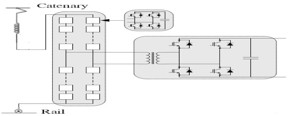 |
| 2007 | Bombardier: Prototype of a 300-kVA, 8-kHz MFT for a 15-kV, 16-2/3-Hz MVAC TPS; all stages have full H-bridges, i.e., AC/DC, DC/AC; AC/DC, respectively; 96 6.5-kV IGBTs; power reduction by 12.5% [67]. |  |
| 2007 | ABB: First prototype for a 1200-kVA PET for a 15-kV, 16-2/3-Hz MVAC TPS; 2-stage multilevel AFE converter, 400-Hz MFT, 3.3-kV IGBTs, and 6.5-kV/400-A IGBTs,;192 IGBTs total; hence, slightly higher efficiency (3%) and higher component count than LFT [88]. | 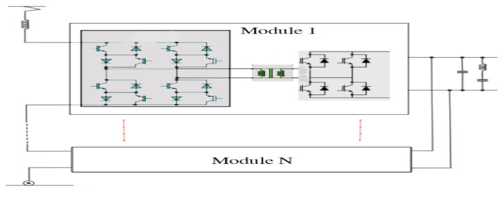 |
| 2012 | ABB: Advanced 1200-kVA PET prototype for a 15-kV, 16-2/3-Hz MVAC TPS; 1st and 2nd stages a full H-bridge (6.5-kV/400-A IGBTs), 3rd a half H-bridge (3.3-kV/800-A IGBTs); MFT 400 Hz; 72 IGBTs total; 96% efficiency [33,89]. | 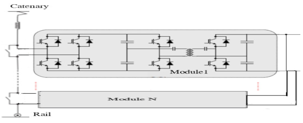 |
| 2014 | ABB: 1.2-MVA PET prototype for a 15-kV, 16-2/3-Hz MVAC TPS; 1.75-Hz MFT, used 6.5-kV/400-A IGBTs and 3.3-kV/800-A IGBTs; cascaded multilevel front-end converter; tested on a locomotive in Geneva, Switzerland; success is a great milestone of the PET technology for railway traction applications [90]. |  |
| Challenges | Solutions |
|---|---|
| New equipment to achieve effective monitoring and controllability. | Distributed and networked SCADA systems with standardized protocols, unlike the traditional SCADA. |
| New signalling and communications system to guarantee quality service while the trains are moving through a range of environments, e.g, remote regions, tunnels, across networks, etc. | New railway signalling and communication; global system mobile communication railway (GSM-R) is a valuable case study for innovation. |
| DER integration issues, i.e., PV and wind intermittencies and site specificities, in addition to the rail traction load variability. | Systems approach in determining the type, number, size, and location of DERs for integration. |
| Data from multiple stakeholders and data processing. | Different sharing agreements and protocols by stakeholders to be redefined by the SG railway. Data feeds from different stakeholders with different notations for trains and stations to be standardized for SG railway management. |
| Cybersecurity against threats to signalling and communication systems. | Technical (a more robust cryptographic mechanism; a new key distribution scheme; a new key storage and system integrity module; and a set of countermeasures for avoiding radio jamming attacks) and policy (cybersecurity-related standards). |
| Standardisation and regulation. | Compliance is best practice for SG railway safety, as well as for technologies to be compatible and interoperable. Standards are necessary for monitoring and control devices; communication systems and protocols; EMC; cybersecurity; and data (collection, storage, and sharing). |
Publisher’s Note: MDPI stays neutral with regard to jurisdictional claims in published maps and institutional affiliations. |
© 2021 by the authors. Licensee MDPI, Basel, Switzerland. This article is an open access article distributed under the terms and conditions of the Creative Commons Attribution (CC BY) license (https://creativecommons.org/licenses/by/4.0/).
Share and Cite
Simiyu, P.; Davidson, I.E. MVDC Railway Traction Power Systems; State-of-the Art, Opportunities, and Challenges. Energies 2021, 14, 4156. https://doi.org/10.3390/en14144156
Simiyu P, Davidson IE. MVDC Railway Traction Power Systems; State-of-the Art, Opportunities, and Challenges. Energies. 2021; 14(14):4156. https://doi.org/10.3390/en14144156
Chicago/Turabian StyleSimiyu, Patrobers, and I. E. Davidson. 2021. "MVDC Railway Traction Power Systems; State-of-the Art, Opportunities, and Challenges" Energies 14, no. 14: 4156. https://doi.org/10.3390/en14144156
APA StyleSimiyu, P., & Davidson, I. E. (2021). MVDC Railway Traction Power Systems; State-of-the Art, Opportunities, and Challenges. Energies, 14(14), 4156. https://doi.org/10.3390/en14144156