1. Introduction
For global warming, nonrenewable fossil energy, and other reasons, electrification of transportation systems have been carried out for many years. In railway systems [
1], the power supply of the train using a pantograph to get electric power from a conductor rail is easy due to the fixed tracks. However, for electric vehicles (EVs), the required high flexibility and the cost makes it unrealistic to attain power in a similar way. Instead, to operate on vast distances, EV has to be equipped with a high-power and large capacity battery pack.
Up to now, EVs have not been very attractive to consumers, even with many government programs. Poor cruise performances of EVs continue to be the primary reason that impends their market penetration. The electric storage technology is the major problem of the EV. It requires a battery with large energy density, long cycle lifetime, and low cost [
2,
3,
4].
The dynamic wireless power transfer (DWPT) charging system for EVs application is a solution to solve the EVs battery dependence. The resonant inductive power transfer discussed in this paper is based on magnetic resonance coupling between the transmitter and the receiver coils defining the coupler [
5,
6,
7].
Recently, as the need for EV charging and technological progress has increased, the powers transferred by WPT and the charging distance have increased from a few millimeters to a hundred millimeters for some kilowatts power level [
8]. Several demonstrations, based on different coupler topologies, have been proven by research institutes and major car suppliers in order to validate the feasibility of such systems [
9,
10,
11,
12].
The magnetic coupling factor of the coupler is expected as the key parameter in DWPT charging system. Several shapes of coils exists and can be integrated into pads to transfer energy from the ground pad to the vehicle one [
11,
13]. Some of these coils are circular (Circ), bipolar (BP), rectangular (Rec), and double D (DD) [
14,
15].
In [
16], the authors proposed an optimization of a circular coil used for static charging of EV. The optimization concerns various parameters such as the coupling factor, number of coils turns, and ferrite thickness, as well as the losses in the aluminum shielding.
Different comparative studies [
17,
18,
19,
20] between these four different shapes (rectangular, circular, DD, and BP) of coils have been carried out in the past. However, most of them take different geometric dimensions for each structure [
14,
21,
22].
In this paper, in order to choose an optimal EV’s inductive power transfer charging system, the authors compared in terms of their coupling coefficient different geometries of coils though keeping the same winding area (available area under the EV).
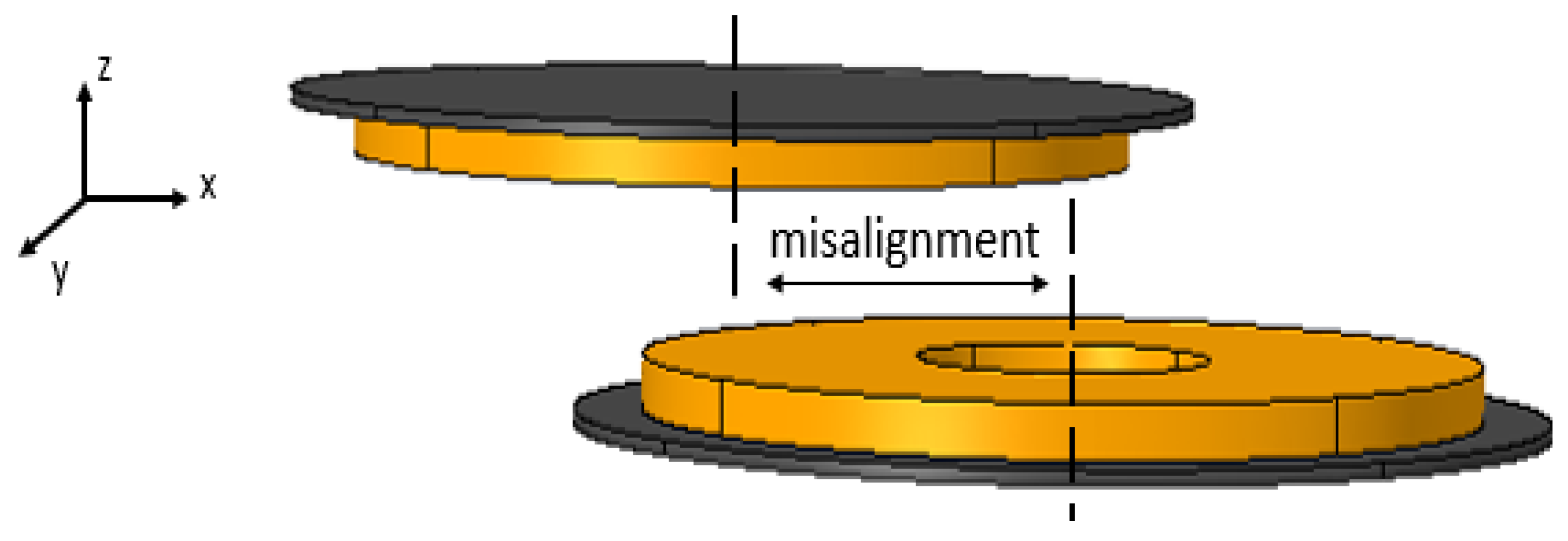
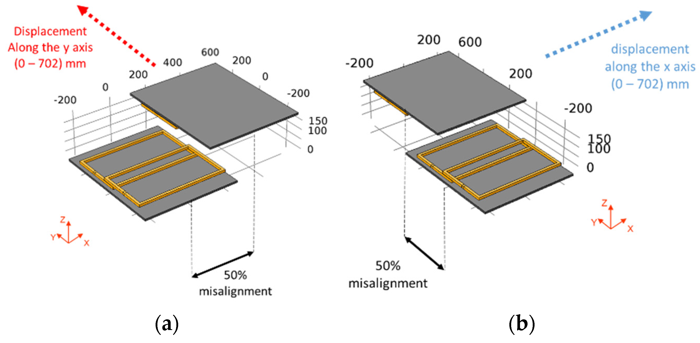
The proposed studies of the magnetic coupling and the field emission evaluation between the primary and secondary coils are taking into account the secondary part motion and its misalignment (
Figure 1) with respect to x and y axes (displacement axis and misalignment axis).
The validity of the proposed approach is demonstrated using finite element calculations based on COMSOL software and on a DWPT test bench designed and available at VEDECOM institute.
2. Dynamic Wireless Power Transfer
2.1. General Description
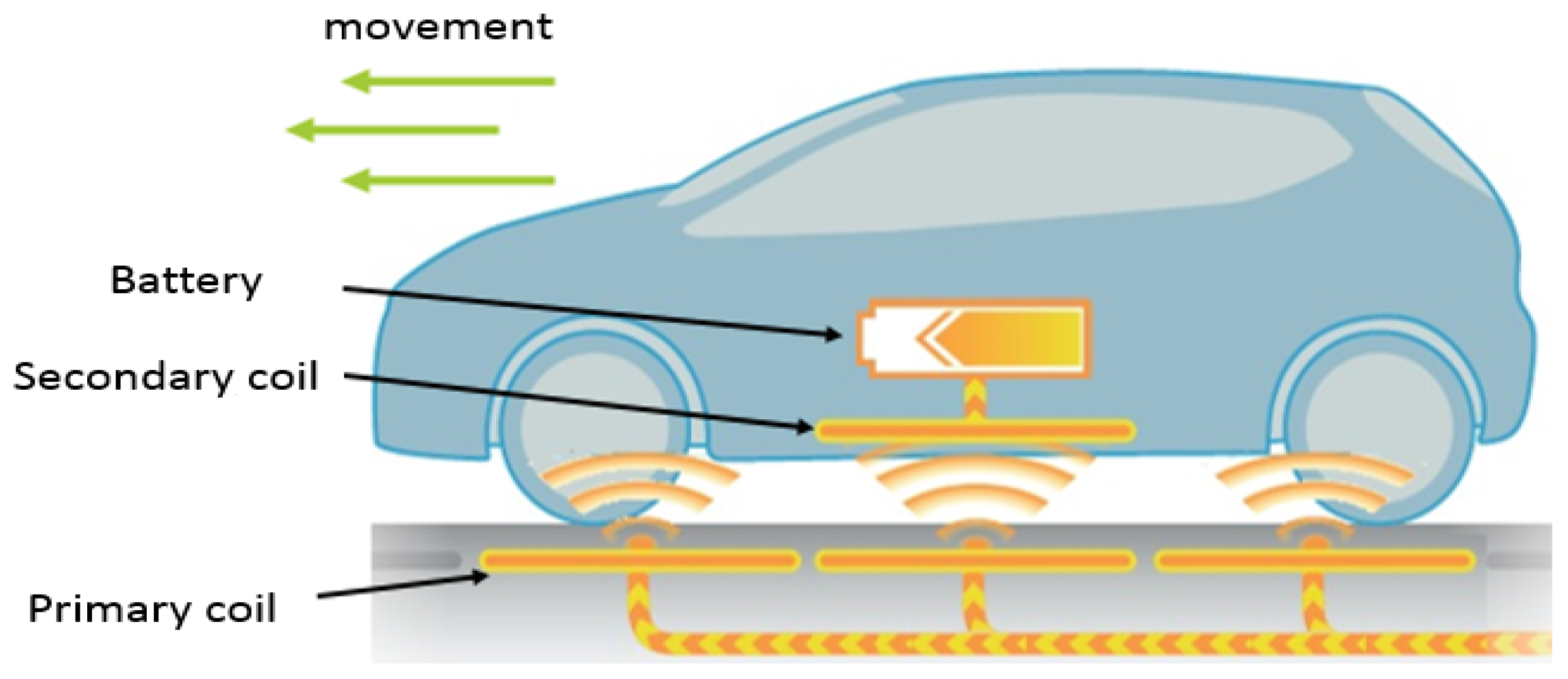
The wireless power transfer (WPT) solution explored in this study relies on the magnetic resonant coupling between the primary ground coil and the secondary vehicle coil. A typical WPT charging system scheme for EV is reported in
Figure 2.
The power of the AC grid is firstly converted to a direct current (DC) using an AC/DC rectifier. Then, the obtained DC power is converted into a high-frequency AC power to feed the transmitting coil through a compensation network. The compensation network reduces the reactive power operating at the resonance frequency close to 85 kHz, fixed by the standards. Indeed, the high positive reactive powers due to the leakage inductances at the two sides of the coils are compensated by capacitors to improve the power transfer capability and efficiency.
Typically, there are four basic resonant topologies of resonant inductive power transfer system, labeled as SS (series–series), SP (series–parallel), PS (parallel–series), PP (parallel–parallel) [
18]. There are other compensation topologies that may be used to improve the performance of the WPT system (for example S–LCC, LCC–S, and LCC); however, more components are required [
24].
Secondly, the high-frequency current in the primary coil generates an alternating magnetic field, inducing an AC voltage at the receiving coil port. By resonating with the secondary compensation network, the transferred power is significantly improved.
The obtained AC transferred power is rectified and transferred to a DC/DC converter to charge the EV battery.
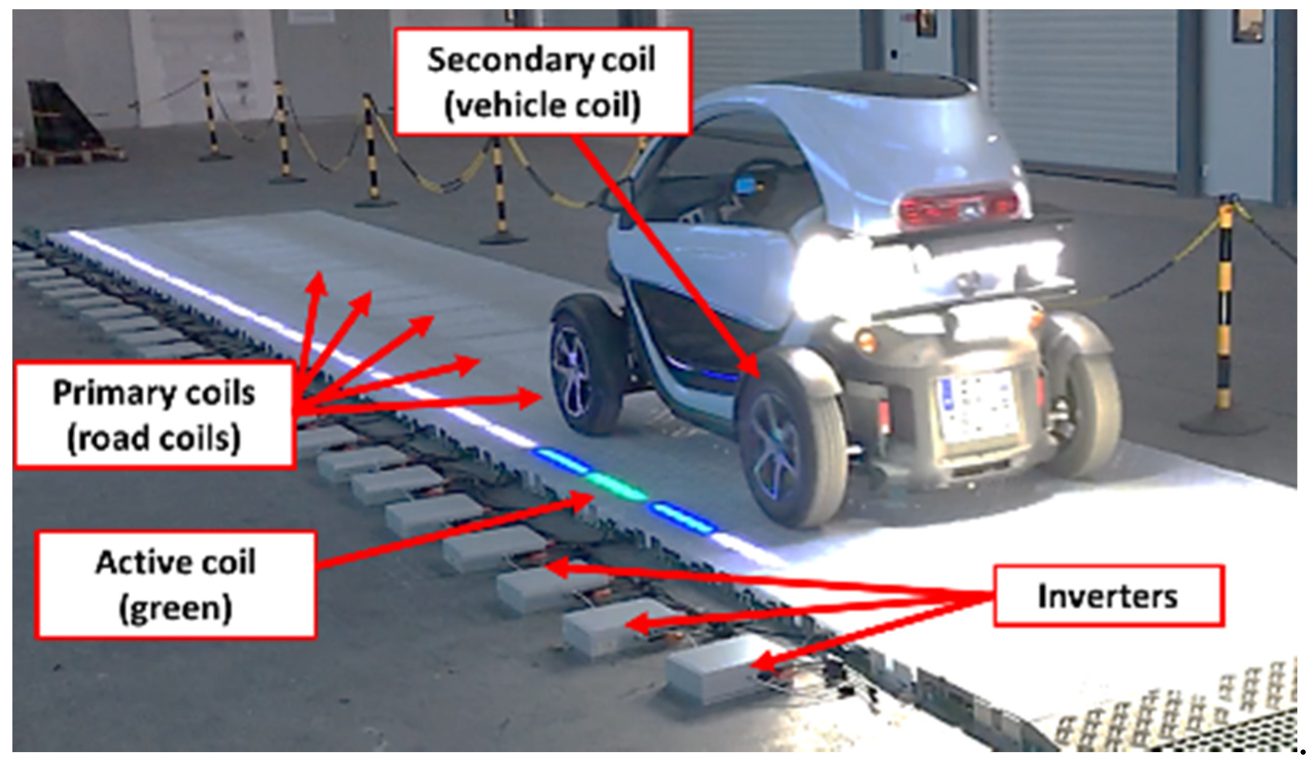
Figure 3 shows a description of a DWPT system, with the primary and secondary coils (coupler).
2.2. Studied DWPT System and Contributions
The studied system during these research activities concerns a DWPT designed for a rated power of 2.5 kW. It feeds a RENAULT Twizy car. The system is shown in
Figure 4. This WPT system is defined as WPT1–Z1 class according to standards like the J2954 [
26], the IEC 61980 [
27], ISO 19363 [
28], and even the IEC 63243 [
29] (standard concerning the DWPT which is being drafted). The Z1 class corresponding to a power level lower than 3.7 kVA, and a coil airgap lower than 150 mm).
The main specifications of charging system are summarized in the following
Table 1.
2.3. Focus on the Magnetic Coupler
The coil design is the most crucial part of the DWPT whole system. Its design significantly affects the performance of the entire system [
15,
31,
32]. The coil configuration must enable the enhancement of the coupling coefficient, reduction of the flux leakage, and shaping of the magnetic field. In dynamic charging, the mutual inductances change with the vehicle displacement, resulting in a decrease of the magnetic flux seen by the secondary coil, and this will affect the ability of the WPT system.
To increase the system efficiency, several methods have been proposed. Some of them concern the resonance frequency tuning [
6,
33], others deal with the tuning of the resonance capacitance to adapt the reactive power compensation during the EV motion [
34,
35,
36], while in [
37] the authors focused on keeping the output power stable by working on an optimization method to improve the system efficiency and regulating the output voltage.
In order to get the optimal coupler structure in the dynamic mode (the vehicle motion), the authors proposed an efficient methodology to evaluate different coil geometries while keeping the same winding area.
In [
14,
15], the authors investigated various configurations of loosely coupled magnetic couplers, which could possibly be used in WPT systems to provide wireless charging of the on-board battery of EVs. More than 8 optimized different structure were compared. Unfortunately, the compared structures were not designed for the same power levels, so they did not have the same number of turns or the same volume of ferrite, nor did they occupy the same dimensions.
In this paper and contrary to what was done in [
14,
15] where the dimensions of the coils were different from one topology to another, the authors considered that the surfaces occupied by the primary and secondary coils remained the same (468 × 468 mm). For the different evaluated topologies, we determined the coupling coefficient and the influence of the displacement and the misalignment on the latter.
3. Coupler Characterization Methodology
To correctly characterize the coupler, 2 different approaches based on numerical calculations and measurements, respectively, were proposed. These two methods provided the electrical parameters of the coupler.
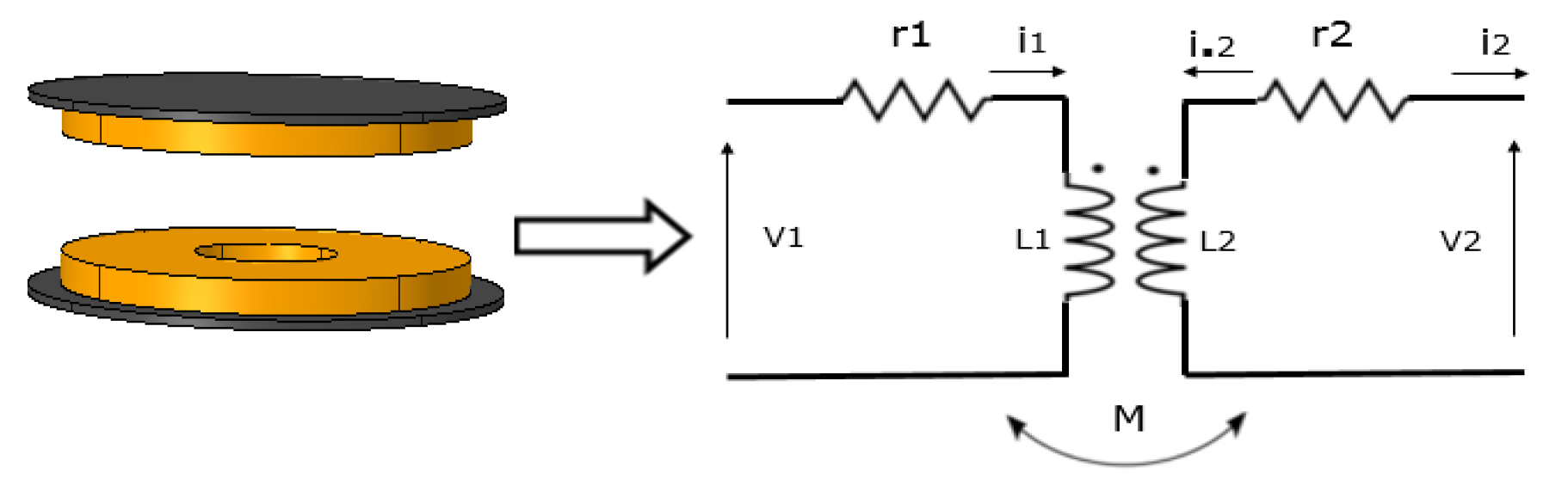
Figure 5 presents the magnetic coupler and its equivalent circuit. Equations (1)–(3) govern this equivalent circuit.
where:
, are the resistance of the primary and secondary coils.
are the self-inductance of the primary and secondary coils.
M is the mutual inductance between primary and secondary coils.
4. EV Pads Study
In order to design the optimal EV coupler topology for a DWPT system, the coupling coefficient of several geometries had to be evaluated. In this case, the winding areas remained the same and the key considered parameters were the coupling factor and influence of dynamic misalignment.
3D simulations corresponding to an electric vehicle DWPT system were carried out and experimental measurements were used to validate these simulations.
The winding area of the real coupler DWPT coils was 48 × 48 cm. This dynamic charging system is mounted on a Twizy (Renault electric car). The corresponding distance between emitter and receiver was 15 cm (Z1 class from SAE Standard).
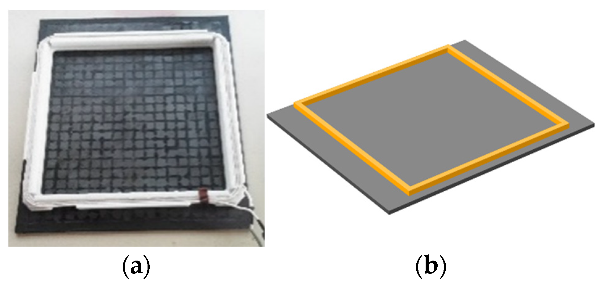
Figure 6a shows a picture of the used WPT coil, while
Figure 6b shows the geometry of this same coil modelized on COMSOL software.
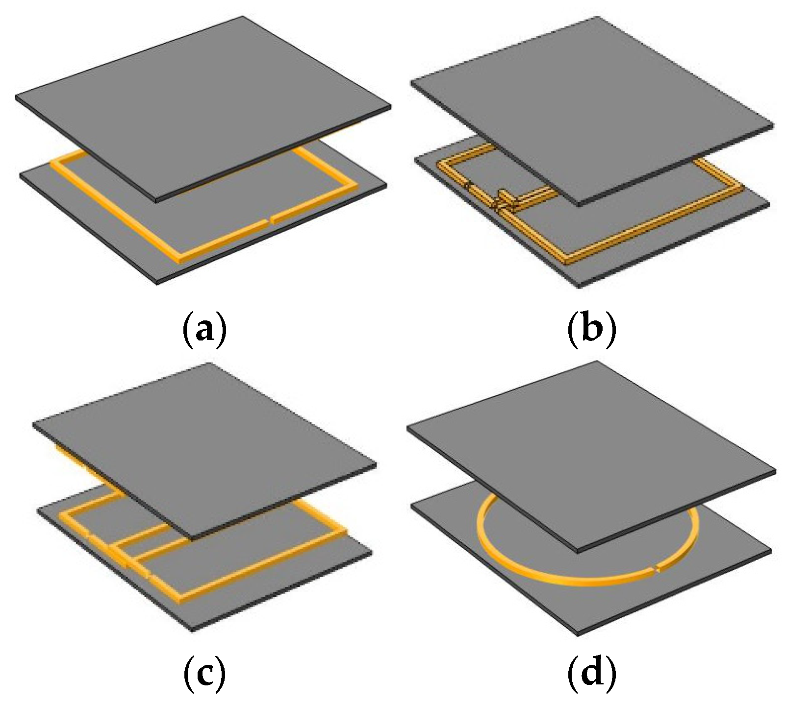
This square coil structure was compared to several others. The considered coupler structures were the most known and used in EV’s charging system in recent years [
14,
15] namely, rectangular–rectangular (Rec–Rec), doubled–doubled (DD–DD), bipolar–bipolar (BP–BP), and circular–circular (Circ–Circ) with ferrite plates.
With ferrites plates, the coils produced a magnetic field mainly on one side, and the magnetic field on the other side of the pad was strongly reduced.
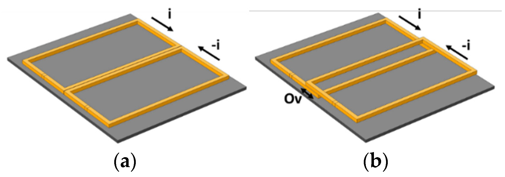
The DD coil (
Figure 7a) as well as the BP coil (
Figure 7b) were each composed of two sub-coils connected in series with an opposite direction current. These sub-coils led to reducing the lateral leakage magnetic flux as the flux mainly flowed from one sub-coil to the other.
The general structure of bipolar coil (BP) (
Figure 7b) was the same as the DD coil, but the coupler was built of two coils with a small overlap. This overlap (noted Ov in
Figure 7b) was calculated to cancel or greatly reduce the mutual inductance between the two sub-coils making BP structure. In this configuration, the two sub-coils acted as two independent and magnetically decoupled coils.
Circular coils (
Figure 8d) are one of the most common topologies for WPT systems (especially in static charging).
Figure 9 and
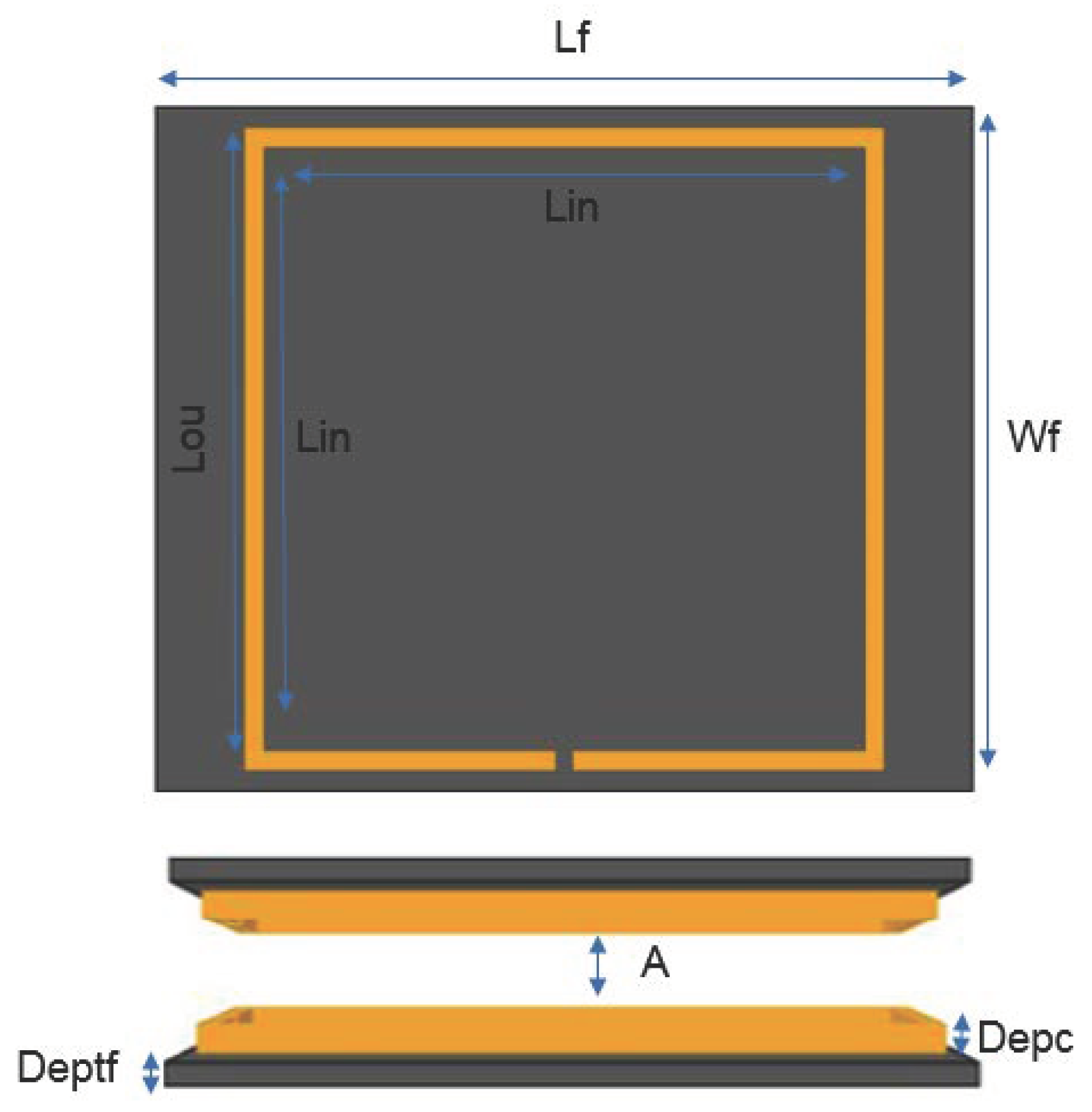
Table 2 illustrate the external dimensions of the different coupler topologies and their materials, and the use in the modeling of a uniform distribution of the current density in the conductors was allowed by the fact that the cables are made from Litz wires.
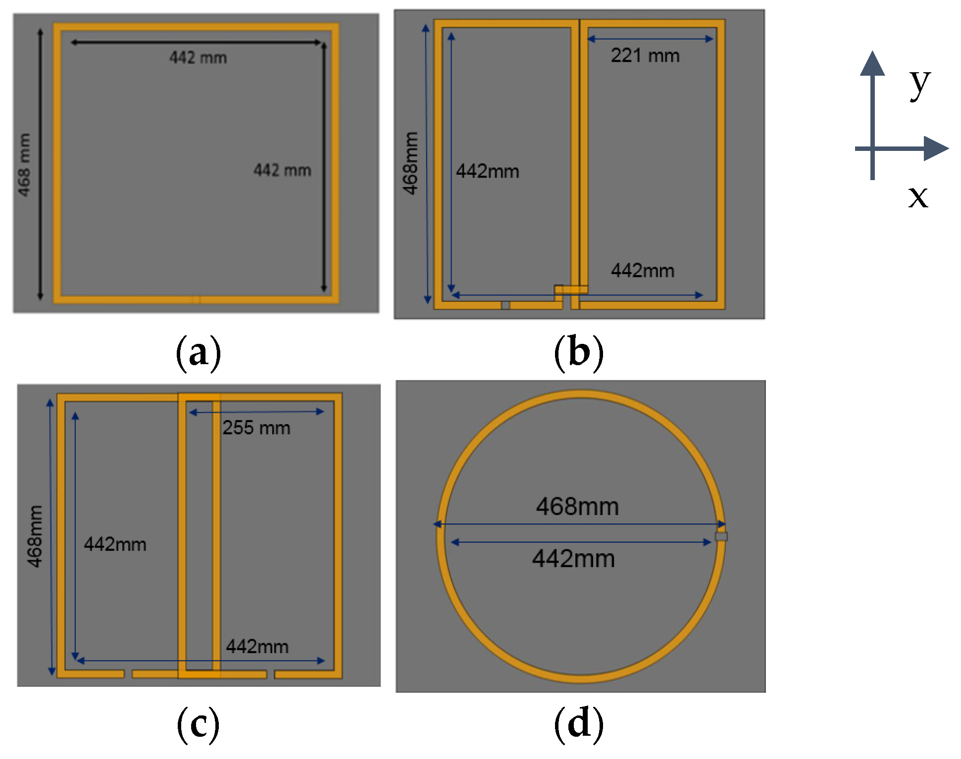
External dimensions of each coupler are kept the same and the shape and dimensions of each coupler coils are given in
Figure 10.
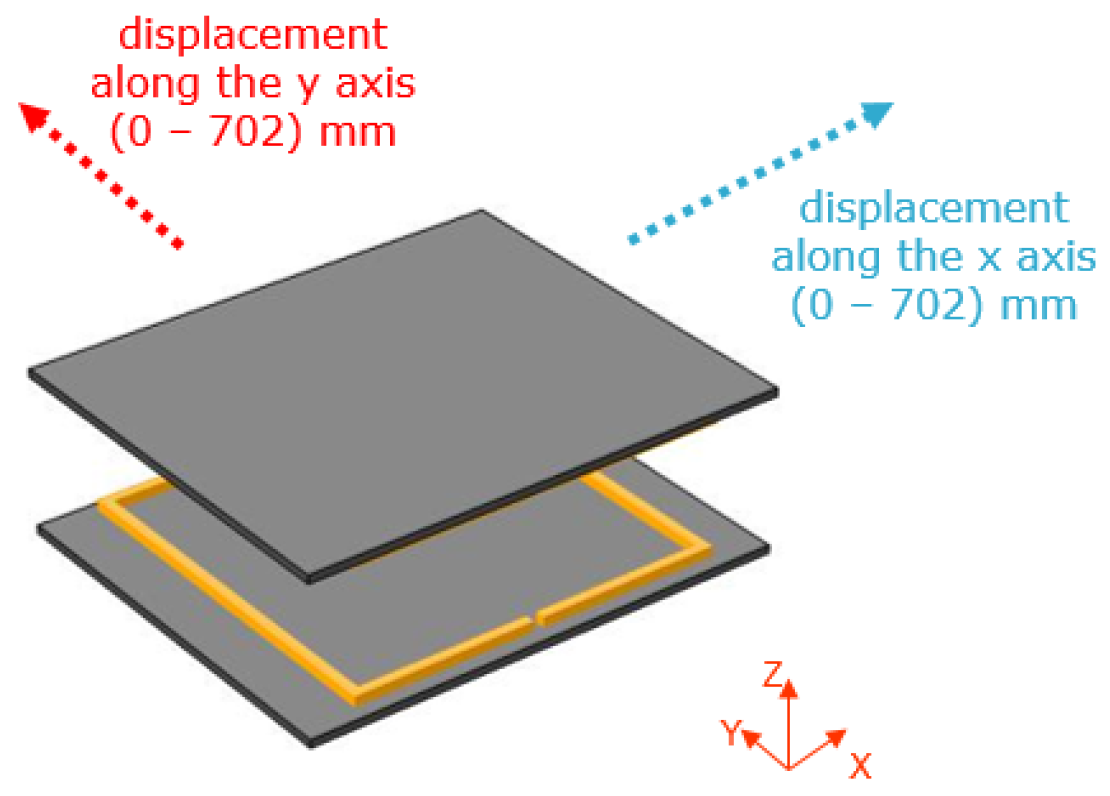
Because of the non-symmetrical system, the study was carried out according to the two axes of displacement (x, y) as shown in
Figure 10 and
Figure 11.
4.1. Coupling Factor Evaluation
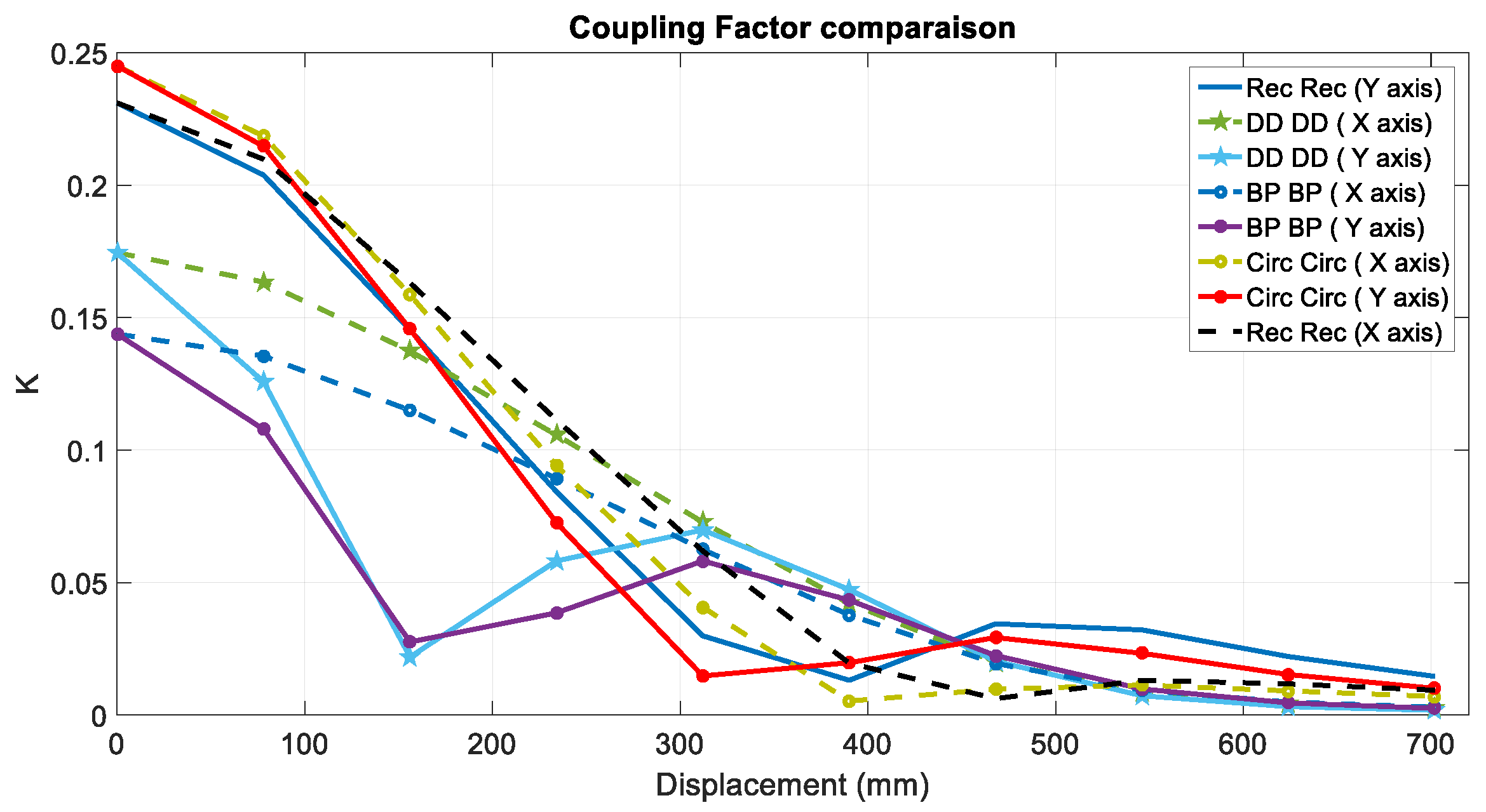
Figure 12 shows the coupling factor or coupling coefficient (k) for the four coils shapes for different displacement (in x and y direction). In this table, k is defined as below:
The results are shown (
Figure 12) in a range of 0 to 702 mm in x and y axes (which corresponds to 154 % of the coil size) in
Figure 12.
As the displacement increased, k decreased for each topology but not in the same way. Circ–Circ topology provided the highest k of 0.245 when the two coils were precisely aligned, whereas BP–BP topology showed the minimum k when the coils were aligned.
From the simulations, it can be noted that DD–DD and BP–BP topologies were relatively less sensitive to displacement in “X” direction (a coupling factor k = 0.1 for a displacement of 50% of the size of the coils). Using these two topologies (DD–DD, BP–BP) a zero coupling was achieved for a displacement of about 37% of the primary pad length in “Y” direction (which is in good agreement with the value of 34% from the study [
14]). The low k and the zero coupling factor of these two shapes were clearly major drawbacks that made these topologies irrelevant for dynamic charging applications, especially knowing that the standard requires recharging when the coupler is misaligned about 50% [
26].
Coupling factor of the Rec–Rec coupler was slightly lower than the circular coupler, but the Rec–Rec coupler was less sensitive to misalignment. This was of great interest for DWPT applications.
In the following simulations (
Figure 13), the same configurations, dimensions, and materials were employed, and the only difference was the misalignment in one direction, while the secondary coil translated in the orthogonal direction. The misalignment distance was chosen to be 227.5 mm (which correspond to 50% of the coils dimensions).
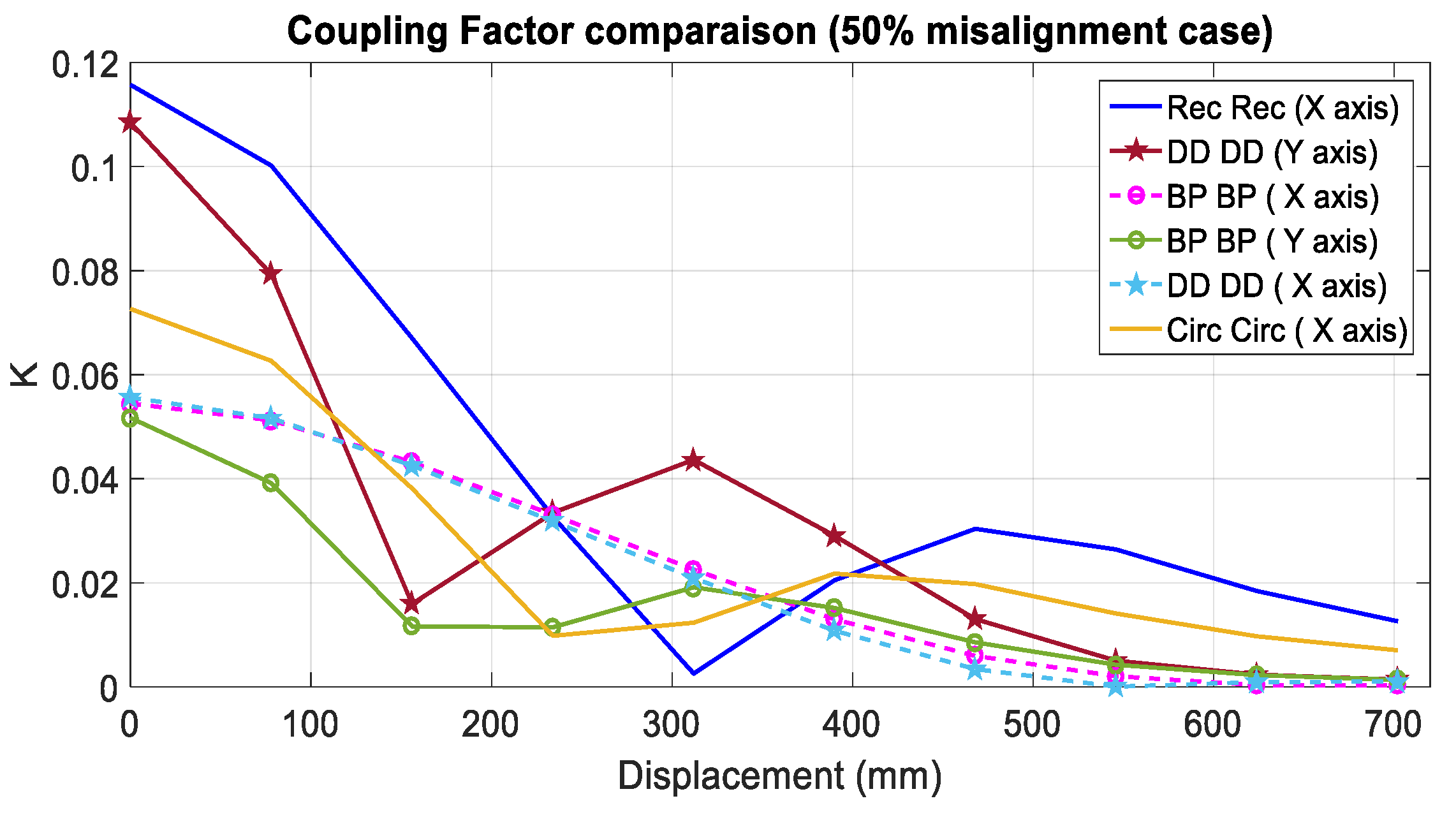
As shown in
Figure 14, the Rec–Rec structure had the highest k factor in this misalignment configuration. This misalignment had a large impact on the Circ–Circ coupler. For this reason, such topology is less interesting in the case of DWPT applications as vehicle alignment on the road is not guaranteed.
4.2. Magnetic Field Emission
Several standards such as IEC 61980 [
27], SAE J2954 [
26], ISO 19363 [
28], and even the IEC 63243 [
29] (standard concerning the DWPT which is being drafted) deal with emission problems, and all these standards refer to ICNIRP 2010 [
39] for the level of recommended field. In France these emission questions are treated by the INERIS (Institut national de l’environnement industriel et des risques) which is a national organization, which is still referring to the ICNIRP 98 [
40] values. All couplers must respect these emission limits to guarantee the safety of the users.
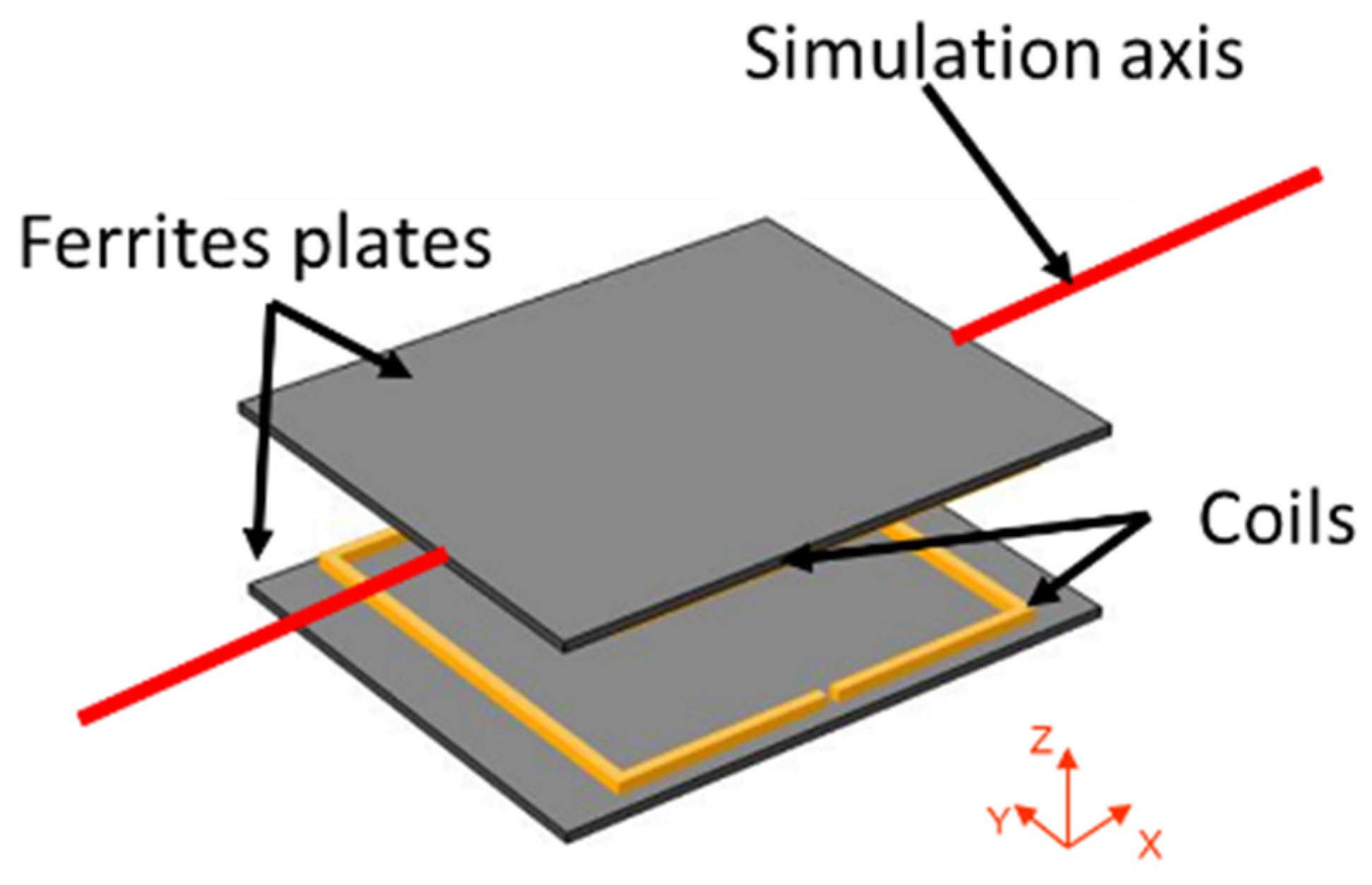
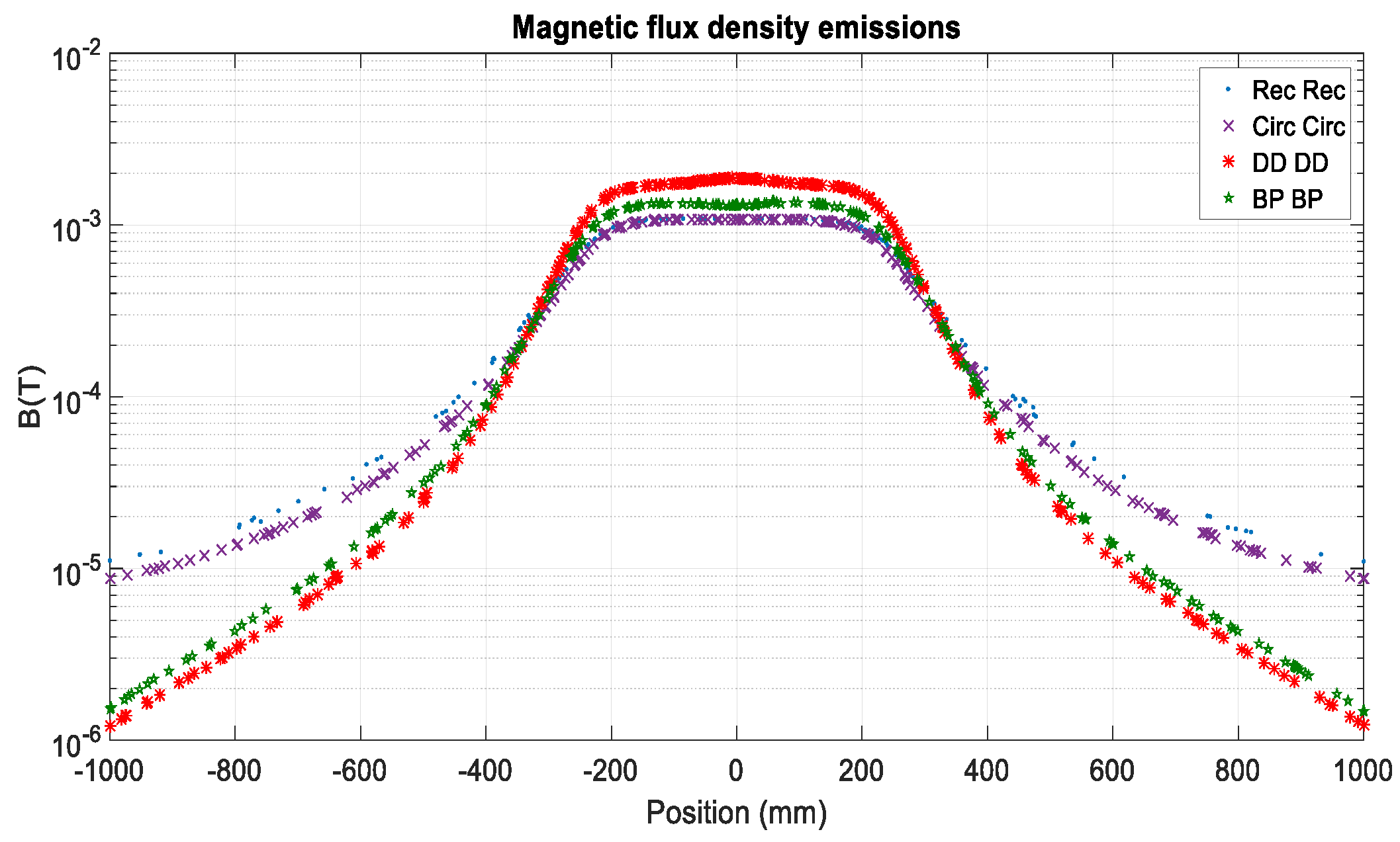
An example of coupler’s emission simulation is given in
Figure 15. In this figure, a Rec–Rec coupler can be seen, the study was carried out for different coupler’s topologies (Circ–Circ, DD–DD, BP–BP) where the primary coil was excited by a current (I
1 = 42 A) and the secondary coil was centered and in open circuit.
The value of the field is simulated on the red line (
Figure 15), which corresponds to a line along the x axis, at the center of the coupler (y = 0, z = 75 mm).
Figure 16 shows the value of the magnetic induction obtained by simulation on the red axis.
The purpose of this study is to define how far the value of 27 μT (RMS) is reached, this value is defined by the ICNIRP 2010 as a limitation for electromagnetic emission [
41]. The smaller is this distance, better it is. This can be explained by the fact that the human body is less exposed to electromagnetic waves at the same distance. From this study, it can be noted that DD–DD and BP–BP offer the better results in term of magnetic leakage. On the other hand, the Rec–Rec and Circ–Circ topologies have poor radiation profile, so at a distance of 1 m from the center of the coupler (and at a height of z = 75 mm), the value of the magnetic field radiated by the circular and rectangular topologies is nearly 10 times higher than that generated by DD and BP coils.
Previous simulations showed that the different WPT system fulfills the ICNIRP 2010 requirements for the magnetic field exposure of the public for different distances (500 mm for DD and nearly 700 mm for Cir or Rec coil shapes).
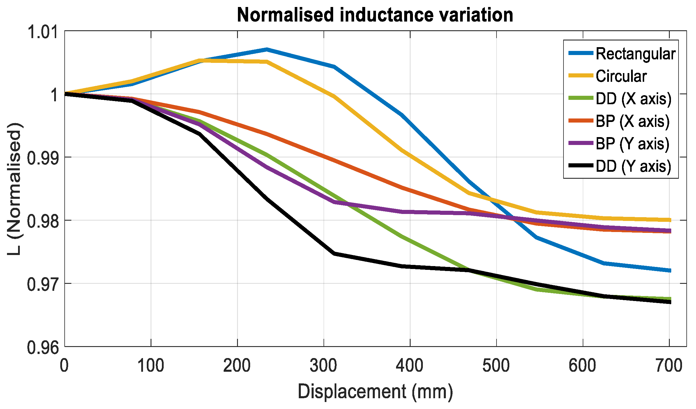
4.3. Inductance Variation
Self-inductances changes when the coils were misaligned from their ideal position. This variation was due to the presence of the secondary ferrite plate, and could affect the system that was detuned and would not be at its resonance frequency (if the inverter frequency is kept constant). These variations affected the performances of the system or in worst cases could deteriorate the power supply.
Figure 17 represents the normalized primary inductance variations as a function of the misalignment.
The Rec–Rec and DD–DD topologies had the most self-inductances variations (3.7 % and 3.3 % respectively). On the other hand, BP–BP (along the x and y axis) and circular structures had the minimum self-inductances variations (2.2% and 2.5 % respectively). Note, however, that these variations were quite low, and that this was therefore not a real criterion for choosing one or the other structure.
5. Experimental Validation
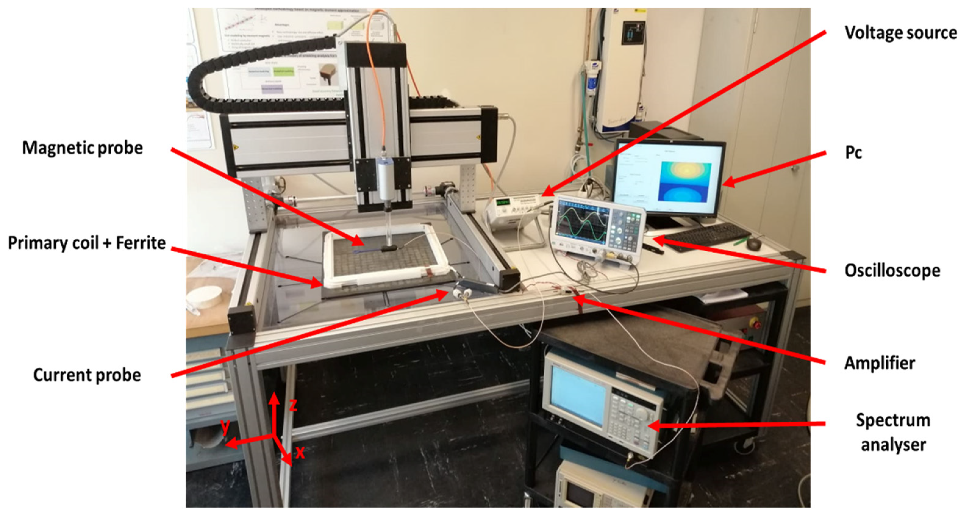
5.1. Magnetic Field Emission
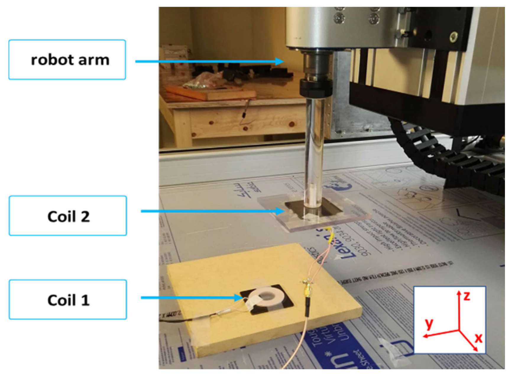
The near field test bench shown in
Figure 18 was used to perform magnetic field measurements. It included a 3-axis robot controlled by a PC, and the robot moved a magnetic probe (MP) over the primary coil with a high precision. A computer controlled the robot and the probe signal was sent to a spectrum analyzer. A low noise amplifier was connected to the output of the MP to improve the field sensitivity. The measurements of the magnetic field radiated by the WPT coil allowed creating magnetic field cartographies.
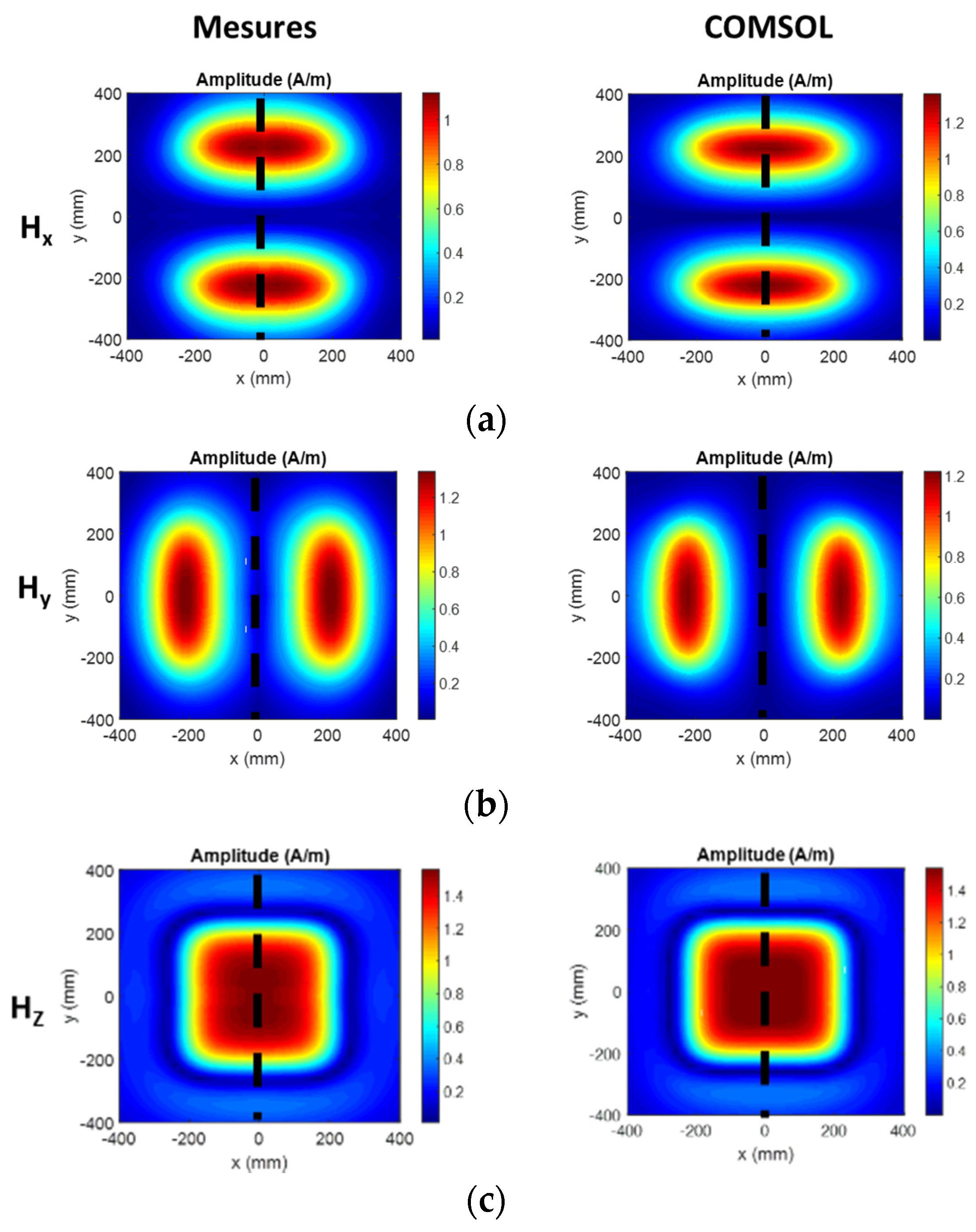
The obtained cartographies for a rectangular primary coil were compared to the simulation results (magnetic field cartographies simulation of the same rectangular coil) in
Figure 19. The current flowing in the coil was equal to 120 mA, and the map was done at 100 mm height (from the top of the coil).
A good agreement of the distribution of the magnetic field between the measurement results and those obtained by numerical simulation was noticed. After this first step which allowed us to validate the previous simulation about magnetic field repartition of different shapes of coils, we were interested in the measurements of self-inductances and couplings of the different forms seen previously.
5.2. Coupling Factor and Self-Inductances Variation
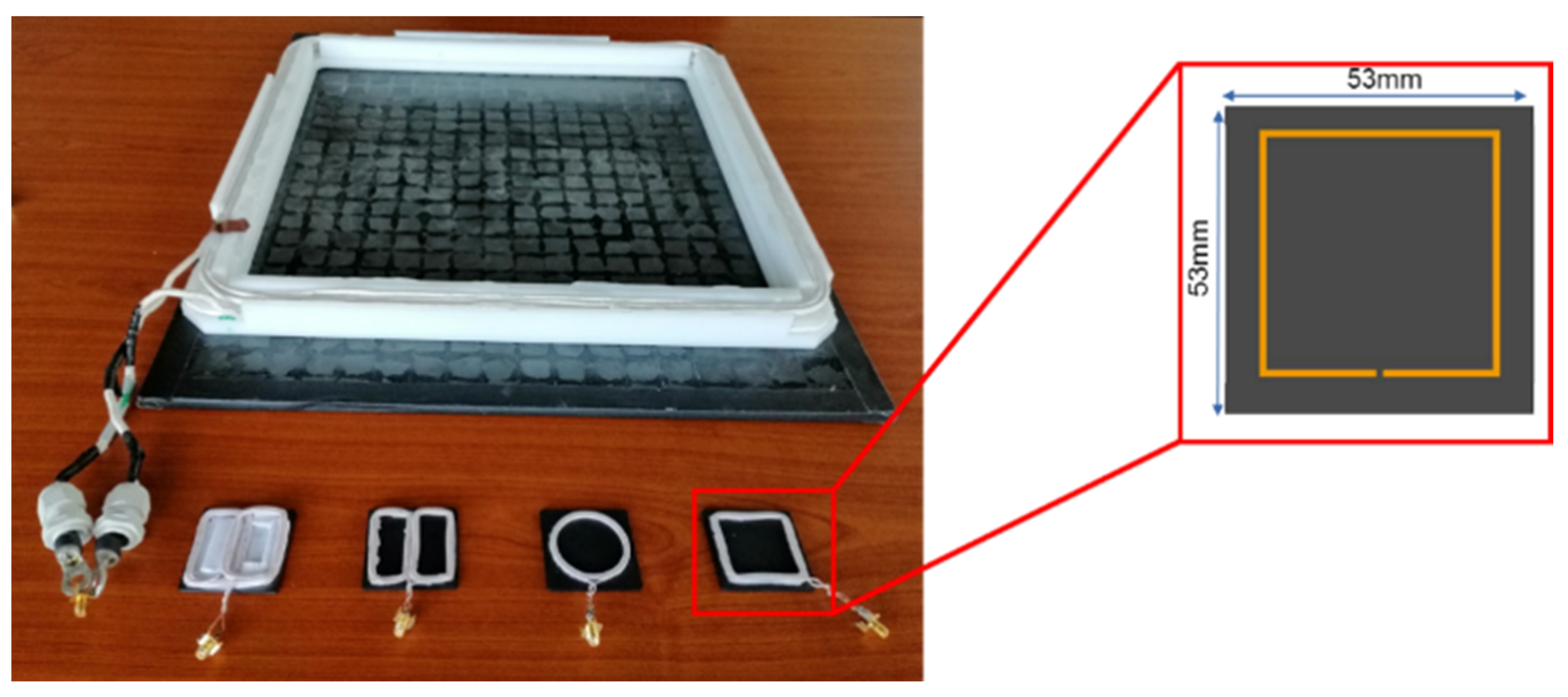
The experimental determination of electrical parameters of the coupler was needed to validate the FEM model used. The production of full-scale coils was very heavy in terms of time and resources, especially knowing the price of the materials used (Litz wire, ferrite). Assuming the absence of saturation in our system, we considered validating the results obtained previously by making coils with reduced size.
These miniature coils were obtained by making a homothety from the real size. This 1:10 scale miniaturization allowed us to validate in the laboratory the results of simulations previously obtained with COMSOL software. The designed coils were built with ferrite plates and Litz wire. We obviously kept the number of turns equal to 6 of the coil on scale 1.
The coupling coefficient should have not changed as long as all the dimensions were divided by the same value. However, it was important to note that certain quantities could not be reduced homothetically as in particular the thickness of the ferrite material.
Figure 20 shows a coil of a full-size coupler and the miniature prototypes produced.
The previous near-field test bench was used to perform the measurements. It permitted us to vary the distance between two coupler coils with a high precision (see
Figure 21).
In total, 10 displacement values were chosen for each topology, starting from 0 (coaxial position) to 50 mm with a step of 5 mm.
Several measurements of the coupling coefficient (8 measurements) were carried out for each value of the displacement (measurements of the various parameters carried out in the same position before proceeding to the next). This made it possible to plot the average value and the standard deviation of measurement of this coefficient. The comparison made between experimental measurements and numerical simulation results presented above (in
Figure 12 and
Figure 14) were carried out taking care to multiply the experimental displacement distances (0 to 50 mm) by the scale factor 10 in order to be directly compared to displacements of the numerical model at a 1:1 scale.
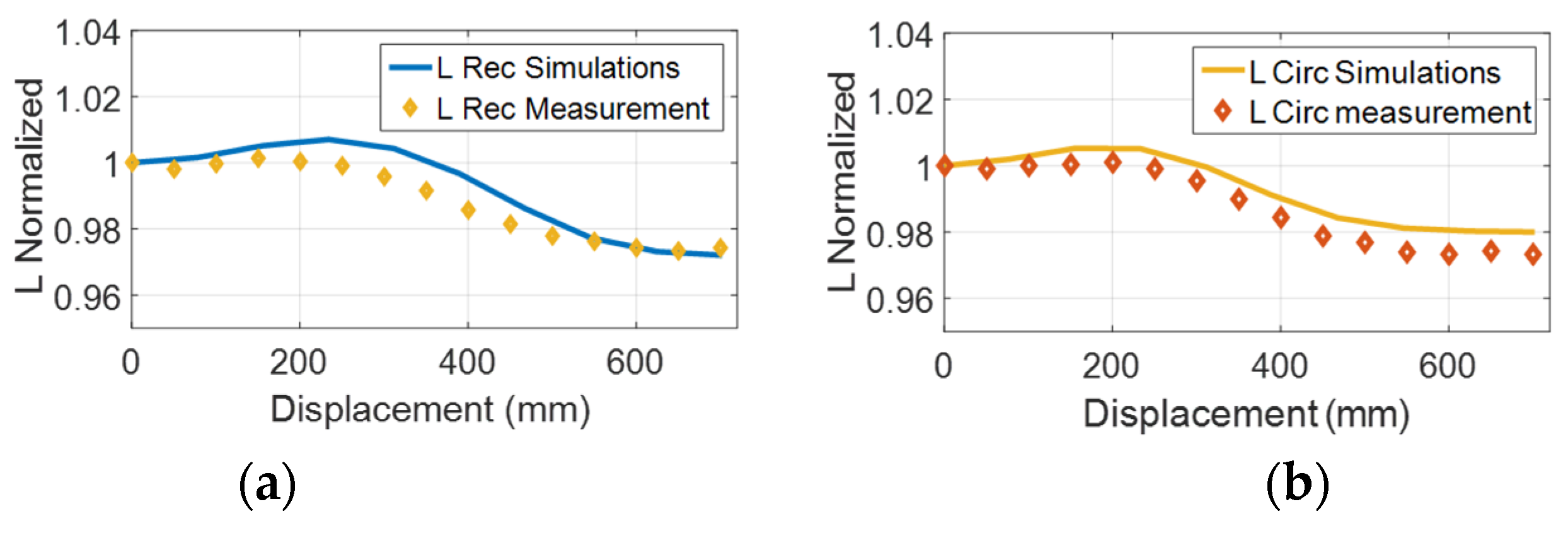
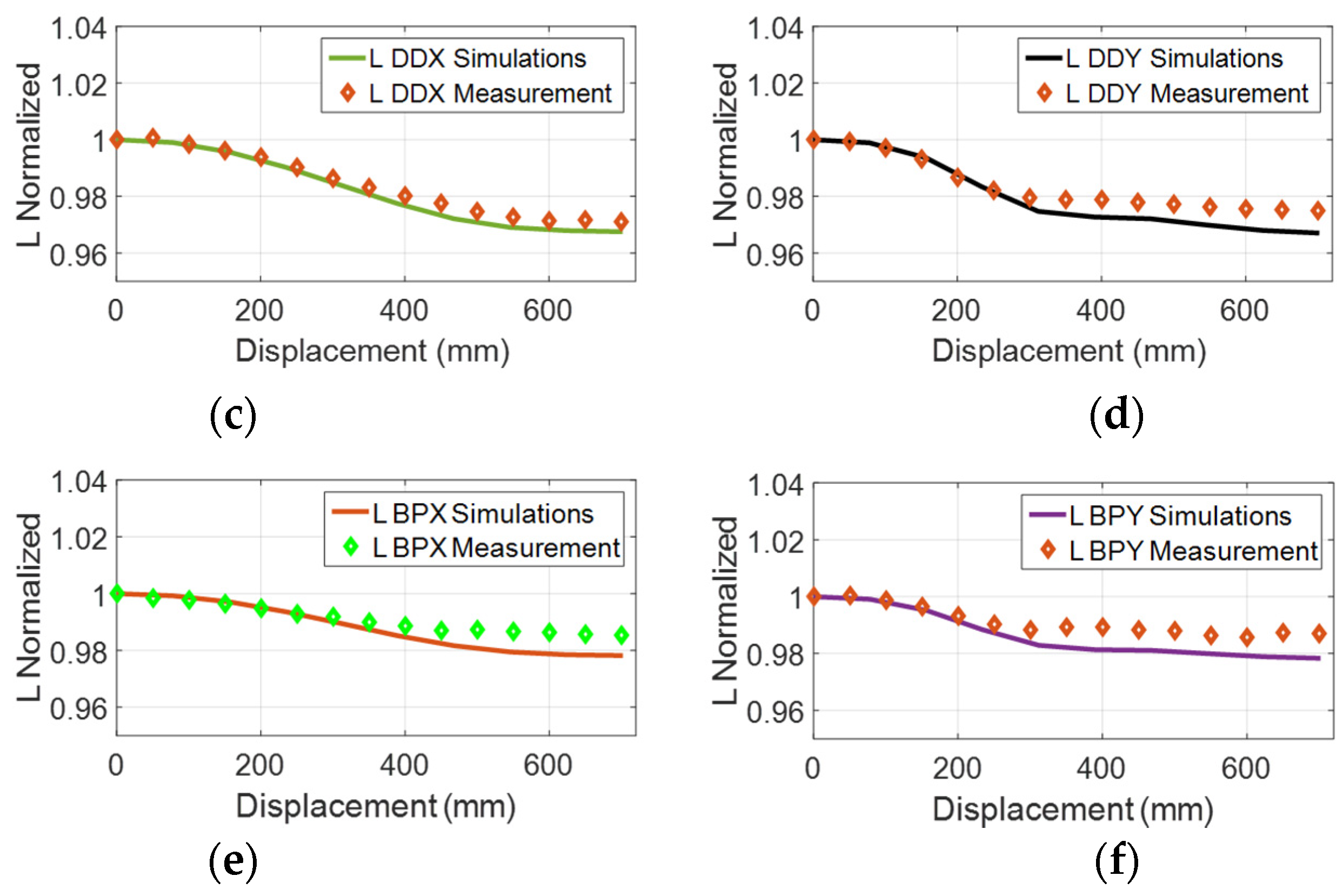
Before talking about the coupling factor comparison,
Figure 22 shows a comparison between normalized self-inductance values obtained by numerical simulation and the normalized self-inductance obtained by measurement. This comparison was done for the four coupler topologies seen before.
The normalized self-inductances values obtained by measurement (multiplied distances (0 to 50 mm) by the scale factor 10 in order to be directly compared to displacements of the numerical model at 1:1 scale) were similar to those obtained by numerical calculation and we focus now on the coupling factor comparison study.
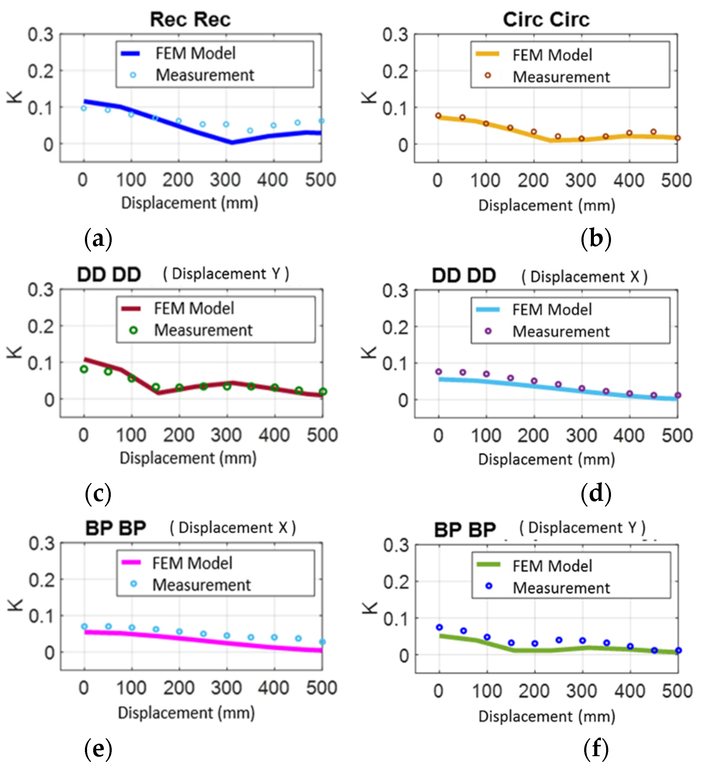
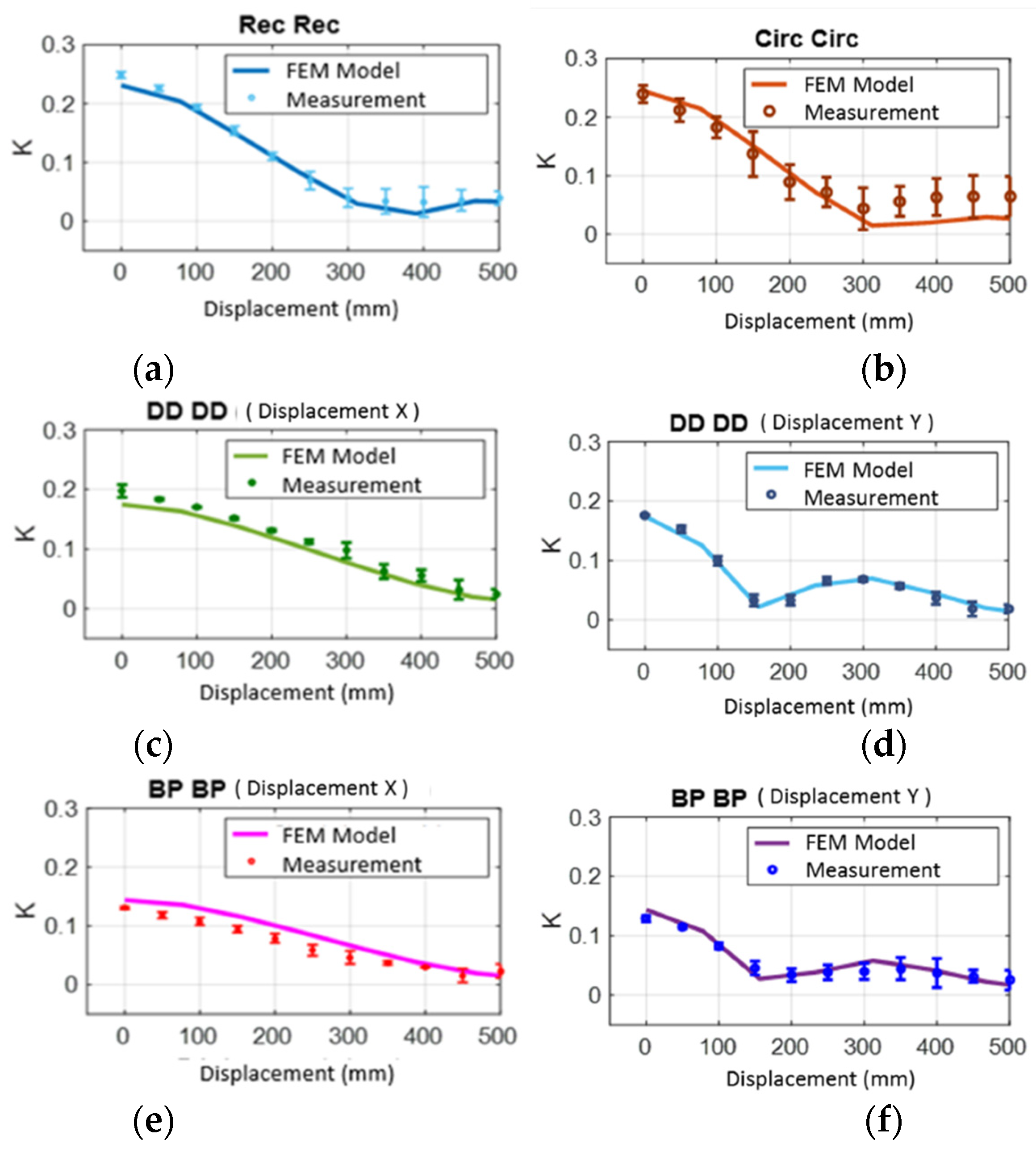
Figure 23 shows the coupling coefficient obtained from numerical simulations and experimental measurements for the four coupler topologies studied previously and for a displacement in the axis of the electric road (no misalignment).
We noted that, and as predicted by the numerical simulations that as the displacement progressed, the coupling coefficient decreased for all the topologies.
Experimentally, the coupling coefficients of the Rec–Rec and Circ–Circ structures were very close and unlike the results of bibliographic studies (which did not take the same coil dimensions) [
14,
21,
22], and the rectangular coupler coupling coefficient was better than the DD.
Experimental results confirmed that the BP–BP structure had the lowest coupling coefficient for the centered position and the presence of a coupling weakening for the DD–DD and BP–BP structures for a displacement along the Y axis of the coils.
Let us now analyze the evolution of the coupling coefficient for an offset movement relative to the electric road (misalignment case). The corresponding results are given in
Figure 24.
We can conclude from
Figure 23 that the shape of the coupling coefficients obtained by measurements on the reduced-scale models corresponded well to those obtained by numerical simulations (
Figure 12 and
Figure 14). However, there were differences between the measured and simulated values, and a small part of these differences was justified by measurement errors. However, the majority of deviations were due to the fact that the coils and couplers were made by hand. There were therefore still errors as to their exact dimensions. The adopted homothety (1: 10) was not fully realized on all dimensions. It was for example impossible to respect this homothety for the thickness of the ferrite material or for the size of the conductors, the latter being unavailable in the exact dimensions sought.
Nevertheless, this experimental part allowed us to confirm the conclusions drawn previously from numerical simulations. Namely, that the circular shape can be privileged and used in a case where the relative positioning of the emitting and receiving coil was perfectly mastered and that the rectangular shape was well suited to DWPT systems because it was tolerant to offset, which represented a key point for the use in dynamic recharging of vehicles for which the positioning on the electric road is not yet fully defined.
6. Conclusion and Future Works
In this paper, investigations for an optimal coupler design for DWPT charging system dedicated to EV were presented.
Despite the existence of many studies on similar subjects, the importance of this comparative study lies in the fact of comparing structures with the same external area (dimensions). Thus, the comparison of four coupler topologies was realized in terms of coupling factor in displacement conditions (alignment and misalignment) on the one hand, and the magnetic field emission on the other hand.
In the aligned configuration, the Circ–Circ topology provided the highest coupling factor. However, this topology was less interesting when the coupler was misaligned; these kinds of structures were more adapted for static wireless charging. On the other hand, the DD–DD and BP–BP structures showed less coupling factor in comparison with the Rec–Rec structure. However, the Rec–Rec topology presented the strongest electromagnetic emission in the environment of the coupler.
In terms of costs, the DD and BP couplers were more expensive, and they required more Litz wires and were more complicated to manufacture, especially for the BP which required a certain positioning of its sub-coils.
This paper also made it possible to see the variation of the self-inductance of the four different topologies according to the displacement and the misalignment. The variation of this parameter was linked to the fact that the recharge was in dynamics (displacement and misalignment of the EV). The importance of this study lies in the fact that this variation can induced errors in the resonance frequencies.
From the comparative results of this paper, the coupler designer was able to choose an appropriate topology of coils, in terms of electromagnetic efficiency for a WPT system.
Future work may focus on the optimization of the magnetic material composing the coupler in order to define the best shape and the best material for the ferrite plates for example. In addition, other improvements could lead to the integration and optimization of an aluminum shielding, especially knowing that such a shielding could strongly influence parameters such as the self-inductance or the coupling factor.
Author Contributions
Conceptualization, K.K., M.B., Y.L.B., E.L., M.D.; methodology, K.K., M.B.; software, K.K., Y.L.B., E.L., M.B.; validation, K.K., M.B.; formal analysis, M.B., Y.L.B., E.L.; investigation, K.K., E.L., M.D.; resources, M.B., Y.L.B., E.L.; data curation, E.L., Y.L.B., M.B.; writing—original draft preparation, K.K., M.B., M.D.; writing—review and editing, E.L., Y.L.B., M.B.; supervision, E.L., M.B., Y.L.B.; project administration, E.L., M.B., Y.L.B., M.D., K.K.; funding acquisition, M.D., M.B. All authors have read and agreed to the published version of the manuscript.
Funding
This research received no external funding.
Conflicts of Interest
The authors declare no conflict of interest.
References
- Rim, C.T.; Mi, C. Wireless Power Transfer for Electric Vehicles and Mobile Devices; John Wiley & Sons: Hoboken, NJ, USA, 2017. [Google Scholar]
- Laporte, S.; Coquery, G.; Deniau, V.; De Bernardinis, A.; Hautière, N.; Bernardinis, D. Dynamic Wireless Power Transfer Charging Infrastructure for Future EVs: From Experimental Track to Real Circulated Roads Demonstrations. World Electr. Veh. J. 2019, 10, 84. [Google Scholar] [CrossRef] [Green Version]
- Coca, E. Wireless Power Transfer Fundamentals and Technologies; InTech: Rijeka, Croatia, 2016. [Google Scholar]
- Cirimele, V. Design and Integration of a Dynamic IPT System for Automotive Applications. Ph.D. Thesis, Universite Paris-Saclay, Paris, France, 2017. [Google Scholar]
- Cirimele, V.; Freschi, F.; Guglielmi, P. Scaling rules at constant frequency for resonant inductive power transfer systems for electric vehicles. Energies 2018, 11, 1754. [Google Scholar] [CrossRef] [Green Version]
- Caillierez, A. Etude et Mise en Oeuvre du Transfert de L’énergie Electrique par Induction: Application à la Route Electrique Pour Véhicules en Mouvement. Ph.D. Thesis, Université Paris-Saclay, Paris, France, 2016. [Google Scholar]
- Boys, J.; Covic, G.; Green, A. Stability and control of inductively coupled power transfer systems. IEE Proc. Electr. Power Appl. 2000, 147, 37. [Google Scholar] [CrossRef]
- Barsari, V.Z.; Thrimawithana, D.J.; Covic, G.A. An inductive coupler array for in-motion wireless charging of electric vehicles. IEEE Trans. Power Electron. 2021, 36, 9854–9863. [Google Scholar] [CrossRef]
- Covic, G.A.; Boys, J.T.; Budhia, M.; Huang, C.-Y. Electric Vehicles—Personal transportation for the future. World Electr. Veh. J. 2010, 4, 693–704. [Google Scholar] [CrossRef] [Green Version]
- Budhia, M.; Covic, G.; Boys, J. A new IPT magnetic coupler for electric vehicle charging systems. In Proceedings of the IECON 2010: 36th Annual Conference on IEEE Industrial Electronics Society, Glendale, CA, USA, 7–10 November 2010; pp. 2487–2492. [Google Scholar]
- Budhia, M.; Boys, J.T.; Covic, G.A.; Huang, C.-Y. Development of a single-sided fluxmagnetic coupler for electric vehicle IPT charging systems. IEEE Trans. Ind. Electron. 2013, 60, 318–328. [Google Scholar] [CrossRef]
- Budhia, M.; Covic, G.A.; Boys, J.T. Design and optimization of circular magnetic structures for lumped inductive power transfer systems. IEEE Trans. Power Electron. 2011, 26, 3096–3108. [Google Scholar] [CrossRef]
- Covic, G.A.; Kissin, M.L.G.; Kacprzak, D.; Clausen, N.; Hao, H. A bipolar primary pad topology for EV stationary charging and highway power by inductive coupling. IEEE Energy Convers. Congr. Expo. 2011, 1832–1838. [Google Scholar] [CrossRef]
- Movagharnejad, H.; Mertens, A. Design optimization of various contactless power transformer topologies for wireless charging of electric vehicles. In 2016 18th European Conference on Power Electronics and Applications (EPE’16 ECCE Europe); Institute of Electrical and Electronics Engineers (IEEE): Piscataway, NJ, USA, 2016; pp. 1–10. [Google Scholar]
- Boys, J.T.; Covic, G.A. IPT Fact Sheet Series: No.2 Magnetic Circuits for Powering Electric Vehicles. 2014. Available online: https://www.qualcomm.com/media/documents/files/ipt-fact-sheet.pdf (accessed on 1 June 2021).
- Corti, F.; Grasso, F.; Paolucci, L.; Pugi, L.; Luchetti, L. Circular Coil for EV Wireless Charging Design and Optimization Considering Ferrite Saturation. In 2019 IEEE 5th International forum on Research and Technology for Society and Industry (RTSI); Institute of Electrical and Electronics Engineers (IEEE): Piscataway, NJ, USA, 2019; pp. 279–284. [Google Scholar]
- Triviño-Cabrera, A.; Aguado, J.A.; González-González, J.M. Wireless Power Transfer for Electric Vehicles: Foundations and Design Approach; Springer: Berlin, Germany, 2020. [Google Scholar]
- Ibrahim, M. Wireless Inductive Charging for Electrical Vehicles: Electromagnetic Modelling and Interoperability Analysis. Ph.D. Thesis, Universite Paris-Sud, Paris, France, 2014. [Google Scholar]
- Kalwar, K.A.; Aamir, M.; Mekhilef, S. Inductively coupled power transfer (ICPT) for electric vehicle charging—A review. Renew. Sustain. Energy Rev. 2015, 47, 462–475. [Google Scholar] [CrossRef] [Green Version]
- Ongayo, D.; Hanif, M. An overview of single-sided and double-sided winding inductive coupling transformers for wireless Electric Vehicle charging. 2015 IEEE 2nd Int. Futur. Energy Electron. Conf. 2015, 1–6. [Google Scholar] [CrossRef]
- Patil, D.; McDonough, M.K.; Miller, J.M.; Fahimi, B.; Balsara, P.T. Wireless power transfer for vehicular applications: Overview and challenges. IEEE Trans. Transp. Electrification 2017, 4, 3–37. [Google Scholar] [CrossRef]
- Yang, Y.; Cui, J.; Cui, X. Design and analysis of magnetic coils for optimizing the coupling coefficient in an electric vehicle wireless power transfer system. Energies 2020, 13, 4143. [Google Scholar] [CrossRef]
- Kadem, K.; Cheriet, F.; Laboure, E.; Bensetti, M.; Le Bihan, Y.; Debbou, M. Sensorless vehicle detection for dynamic wireless power transfer. In Proceedings of the 2019: 21st European Conference on Power Electronics and Applications, Genova, Italy, 2–6 September 2019; pp. 1–6. [Google Scholar]
- Corti, F.; Paolucci, L.; Reatti, A.; Grasso, F.; Pugi, L.; Tesi, N.; Grasso, E.; Nienhaus, M. A comprehensive comparison of resonant topologies for magnetic wireless power transfer. In Proceedings of the 2020 IEEE 20th Mediterranean Electrotechnical Conference (MELECON), Palermo, Italy, 16–18 June 2020; pp. 582–587. [Google Scholar]
- Kadem, K.; Le Bihan, Y.; Bensetti, M.; Laboure, E.; Diet, A.; Debbou, M. Reduction of the shielding effect on the coupling factor of an EV WPT system. In 2019 IEEE PELS Workshop on Emerging Technologies: Wireless Power Transfer (WoW); Institute of Electrical and Electronics Engineers: Piscataway, NJ, USA, 2019; pp. 21–24. [Google Scholar]
- SAE International. Wireless Power Transfer for Light-Duty Plug-In/Electric Vehicles and Alignment Methodology; SAE International: Warrendale, PA, USA, 2017. [Google Scholar]
- International Electrotechnical Commission. Electric Vehicle Wireless Power Transfer (WPT) Systems—Part 1: General Requirements; International Electrotechnical Commission: Geneva, Switzerland, 2019. [Google Scholar]
- International Organization for Standardization. Electrically Propelled Road Vehicles—Magnetic Field Wireless Power Transfer—Safety and Interoperability Requirements; International Organization for Standardization: Geneva, Switzerland, 2018. [Google Scholar]
- nternational Electrotechnical Commission. Interoperability and Safety of Dynamic Wireless Power Transfer (WPT) for Electric Vehicles; International Electrotechnical Commission: Geneva, Switzerland, 2021. [Google Scholar]
- Kadem, K.; Benyoubi, F.; Bensetti, M.; Le Bihan, Y.; Labouré, E.; Debbou, A.M. An efficient method for dimensioning magnetic shielding for an induction electric vehicle charging system. Prog. Electromagn. Res. 2021, 170, 153–167. [Google Scholar] [CrossRef]
- Boys, J.T.; Covic, G.A. Inductive Power Transfer Systems (IPT) Fact Sheet: No. 1—Basic Concepts. 2013. Available online: https://www.qualcomm.com/documents/inductive-power-transfer-systems-ipt-fact-sheet-no-1-basic-concepts (accessed on 1 June 2021).
- Bosshard, R.; Muhlethaler, J.; Kolar, J.W.; Stevanovic, I. Optimized magnetic design for inductive power transfer coils. In Proceedings of the 2013 Twenty-Eighth Annual IEEE Applied Power Electronics Conference and Exposition (APEC), Long Beach, CA, USA, 17–21 March 2013; pp. 1812–1819. [Google Scholar]
- Caillierez, A.; Sadarnac, D.; Jaafari, A.; Loudot, S. Unlimited range for electric vehicles. In 2014 International Symposium on Power Electronics, Electrical Drives, Automation and Motion; Institute of Electrical and Electronics Engineers (IEEE): Piscataway, NJ, USA, 2014; pp. 941–946. [Google Scholar]
- Lee, J.; Lim, Y.-S.; Yang, W.-J.; Lim, S.-O. Wireless power Transfer system adaptive to change in coil separation. IEEE Trans. Antennas Propag. 2013, 62, 889–897. [Google Scholar] [CrossRef]
- Lim, Y.; Tang, H.; Lim, S.; Park, J. An adaptive impedance-matching network based on a novel capacitor matrix for wireless power transfer. IEEE Trans. Power Electron. 2014, 29, 4403–4413. [Google Scholar] [CrossRef]
- Corti, F.; Reatti, A.; Nepote, A.; Pugi, L.; Pierini, M.; Paolucci, L.; Grasso, F.; Grasso, E.; Nienhause, M. A secondary-side controlled electric vehicle wireless charger. Energies 2020, 13, 6527. [Google Scholar] [CrossRef]
- Liu, Y.; Mai, R.; Liu, D.; Li, Y.; He, Z. Efficiency optimization for wireless dynamic charging system with overlapped DD coil arrays. IEEE Trans. Power Electron. 2017, 33, 2832–2846. [Google Scholar] [CrossRef]
- Debbou, M.; Colet, F.; Kadem, K. Wireless inductive power transfer: Design and control for an optimal operation. In Proceedings of the 2018 20th European Conference on Power Electronics and Applications, Riga, Latvia, 17–21 September 2018; Volume 2018, pp. 1–8. [Google Scholar]
- Matthes, R.; Bernhardt, J.H.; McKinlay, A.F. International Commission on Non-Ionizing Radiation Protection (ICNIRP), guidelines on limiting exposure to non-ionizing radiation: A reference book based on the guidelines on limiting exposure to non-ionizing radiation and statements on special applicati. Health Phys. 1990, 74, 375. [Google Scholar]
- International Commission on Non-Ionizing Radiation Protection. Guidelines for limiting exposure to time-varying electric, magnetic and electromagnetic fields (up to 300 GHz). Health Phys. 1998, 74, 494–522. [Google Scholar]
- International Commission on Non-Ionizing Radiation Protection. Guidelines for limiting exposure to time-varying electric and magnetic fields (1 Hz TO 100 kHz). Health Phys. 2010, 99, 818–836. [Google Scholar] [CrossRef] [PubMed]
Figure 1.
Misalignment case [
23].
Figure 1.
Misalignment case [
23].
Figure 2.
Typical WPT charging system for EVs.
Figure 2.
Typical WPT charging system for EVs.
Figure 3.
Dynamic induction charging of an electric vehicle [
25].
Figure 3.
Dynamic induction charging of an electric vehicle [
25].
Figure 4.
VEDECOM DWPT charging system test bench [
30].
Figure 4.
VEDECOM DWPT charging system test bench [
30].
Figure 5.
Magnetic circular coupler and its equivalent circuit [
38].
Figure 5.
Magnetic circular coupler and its equivalent circuit [
38].
Figure 6.
Coil form of the Twizy WPT system, (a) picture of the primary coil, (b) coil modeled by COMSOL software.
Figure 6.
Coil form of the Twizy WPT system, (a) picture of the primary coil, (b) coil modeled by COMSOL software.
Figure 7.
Detailed view of (a) DD coil, (b) BP structures.
Figure 7.
Detailed view of (a) DD coil, (b) BP structures.
Figure 8.
Coupler forms (a) Rec–Rec, (b) DD–DD, (c) BP–BP, (d) Circ–Circ.
Figure 8.
Coupler forms (a) Rec–Rec, (b) DD–DD, (c) BP–BP, (d) Circ–Circ.
Figure 9.
Coupler dimensions.
Figure 9.
Coupler dimensions.
Figure 10.
Front view of the different forms of coils, (a) rectangular, (b) double D, (c) bipolar, (d) circular.
Figure 10.
Front view of the different forms of coils, (a) rectangular, (b) double D, (c) bipolar, (d) circular.
Figure 11.
Definition of displacement axes.
Figure 11.
Definition of displacement axes.
Figure 12.
Coupling factor for different displacement positions.
Figure 12.
Coupling factor for different displacement positions.
Figure 13.
Displacement with misalignment, (a) displacement along the y axis, (b) displacement along the x axis.
Figure 13.
Displacement with misalignment, (a) displacement along the y axis, (b) displacement along the x axis.
Figure 14.
The displacement axes (with 50% misalignment).
Figure 14.
The displacement axes (with 50% misalignment).
Figure 15.
Configuration for emission simulation.
Figure 15.
Configuration for emission simulation.
Figure 16.
Electromagnetic induction norm B (T) along red axis of
Figure 15.
Figure 16.
Electromagnetic induction norm B (T) along red axis of
Figure 15.
Figure 17.
Normalized primary inductances vs. displacement.
Figure 17.
Normalized primary inductances vs. displacement.
Figure 18.
Near-field test bench.
Figure 18.
Near-field test bench.
Figure 19.
Magnetic field cartographies comparison at a height of 100 mm. (a) x component of the magnetic field; (b) y component of the magnetic field; (c) z component of the magnetic field.
Figure 19.
Magnetic field cartographies comparison at a height of 100 mm. (a) x component of the magnetic field; (b) y component of the magnetic field; (c) z component of the magnetic field.
Figure 20.
Miniaturized prototypes made in the laboratory.
Figure 20.
Miniaturized prototypes made in the laboratory.
Figure 21.
Used test bench.
Figure 21.
Used test bench.
Figure 22.
Measurement of normalized self-inductance compared to simulation results. (a) rectangular; (b) circular; (c) DDX; (d) DDY; (e) BPX; (f) BPY.
Figure 22.
Measurement of normalized self-inductance compared to simulation results. (a) rectangular; (b) circular; (c) DDX; (d) DDY; (e) BPX; (f) BPY.
Figure 23.
Comparison of the coupling coefficient measured and simulated for different topologies of coils for a displacement in the axis of the electric road. (a) rectangular; (b) circular; (c) DDX; (d) DDY; (e) BPX; (f) BPY.
Figure 23.
Comparison of the coupling coefficient measured and simulated for different topologies of coils for a displacement in the axis of the electric road. (a) rectangular; (b) circular; (c) DDX; (d) DDY; (e) BPX; (f) BPY.
Figure 24.
Comparison of the measured and simulated coupling coefficient for different topologies of coils for misaligned displacement with respect to the electric road. (a) rectangular; (b) circular; (c) DDX; (d) DDY; (e) BPX; (f) BPY.
Figure 24.
Comparison of the measured and simulated coupling coefficient for different topologies of coils for misaligned displacement with respect to the electric road. (a) rectangular; (b) circular; (c) DDX; (d) DDY; (e) BPX; (f) BPY.
Table 1.
DWPT system.
| Parameter | Value |
|---|
| Transferred power | 2.5 kW |
| DC input voltage | 60 V |
| Coupling coefficient | From 0.1 to 0.3 |
| Turns number | 6 |
| Primary and secondary inductances | 63 µH |
| Primary and secondary resonant capacitor | 56 nF |
| Switching frequency | 81.38 to 90.00 kHz |
| System efficiency | 92 % |
Table 2.
Coupler dimensions.
Table 2.
Coupler dimensions.
| Parameters | Values | Comments |
|---|
| A | 150 mm | Air gap |
| Deptf | 10 mm | ferrite thickness |
| Depc | 13 mm | Coil thickness |
| Lf | 600 mm | ferrite length |
| Wf | 500 mm | ferrite width |
| Lou | 468 mm | Coil external length |
| Lin | 442 mm | Coil internal length |
| Wire type | Litz |
| Ferrite material | 3C98 from Ferroxcube company |
| Publisher’s Note: MDPI stays neutral with regard to jurisdictional claims in published maps and institutional affiliations. |
© 2021 by the authors. Licensee MDPI, Basel, Switzerland. This article is an open access article distributed under the terms and conditions of the Creative Commons Attribution (CC BY) license (https://creativecommons.org/licenses/by/4.0/).


 ,
, 


