Abstract
Adopting eco-friendly solutions is the need of the hour in order to downscale carbon emissions and the fast depletion of fossil fuels. Hybrid energy systems provide one such optimistic sustainable solution for power generation in a grid integrated system as well as for stand-alone applications. With grid integrated systems, there are many grid codes to be maintained such as voltage stability, frequency deviation and Fault Ride Through Capability (FRT). In a hybrid system, the propensity of the PV/Wind system to remain connected at the moment of short electric fault is identified as FRT. This paper elucidates the voltage compensation using an Electric Vehicle (EV) charging station or a Flexible AC Transmission System (FACTS) device depending on the intensity of fault that occurs at the Point of Common Coupling (PCC) in grid integrated hybrid systems. When a fault occurs at the PCC, depending on the intensity of the voltage sag either the EV charging station or a FACTS device, namely a Dynamic Voltage Restore (DVR), provides the voltage compensation. The voltage obtained from an EV charging station or DVR is conditioned using power converters and fed to the PCC to even out the discrepancy in the voltage that is effected due to the fault. Even though charges electric vehicles continuously, the EV charging station gives priority to supply voltage for compensation whenever a fault occurs at the grid. If the intensity of voltage sag due to fault is between 0.9 to 0.51 p.u, the EV charging station provides voltage compensation, and for voltage sag between 0.5 to 0.2 p.u, DVR takes over to provide voltage compensation for the continuous sustainability of the grid. The proposed system makes use of an existing source such as an EV charging station as a supplementary device to provide compensation, and also has a backup supplementary device DVR in case of any non-availability of the EV charging station. Thus, the voltage compensation in turn facilitates the parameters such as DC link voltage and the grid voltage to stay within the pertinent limits in the event of a fault at the grid. The system was simulated using MATLAB Simulink and the results were verified.
1. Introduction
Power quality is a significant consternation in modern day power systems. This concern for the issues in the power quality has prompted the development of certain standards and regulations in grid integrated applications. The occurrence of faults in grid integrated systems is one of the major determinants of power quality issues. Relative to the propinquity of the fault in the system that is being considered, the impact of the fault on the system vary significantly causes variations in the voltage and current values. In extreme cases it may lead even to blackouts. Therefore, a progressive research is being carried out in developing a fault tolerant hybrid system and effective methods to diligently compensate the variation of the voltage at the PCC due to the fault.
Grid codes in many countries have been modified in the span of last few years to meet the technical requisites needed for a hybrid system. The grid codes considered for grid integration of hybrid systems in India are active and reactive power control, FRT capability, and communication requirements. Among them, the most demanding one is the FRT capability. This phenomenon denotes the capability of a hybrid system to stay connected for a short time in the event of any fault. This ensures that for the faults that can be normally cleared that there is apparently no loss in the generation of power from the hybrid system. Figure 1 depicts the characteristics of FRT as per grid code in India [1]. As it can be seen from the characteristics in Figure 1, Vf is 15% of nominal voltage and Vpf is the minimum rated voltage. Hence the duration where the wind turbine and PV panel continues to remain in the system as the voltage drops from the rated value to its 15% of its value at the onset of fault is only 3 s. Hence, voltage compensation is very much essential to restore the voltage sag within this time limit. In the literature, voltage compensation during faults with many supplementary devices exists. Hence, this paper mainly focuses on this concept of voltage compensation during faults by utilizing the available sources, such as an EV charging station. Additionally, a secondary FACTS device is tied to the grid to provide compensation during the non-availability of EV charging station as well to efficiently tackle intense voltage sag.
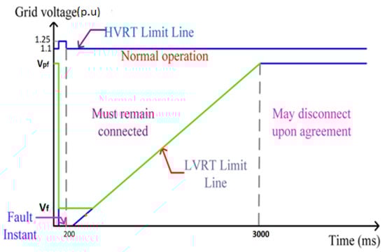
Figure 1.
Fault ride through characteristics.
Hybrid power solutions have become a necessity, as conventional fossil fuels are diminishing day by day. When these hybrid systems are integrated with the grid, it is necessary to protect the sources and power converters when the fault occurs at the grid. Many protection circuits such as crowbar protection, DC copper protection, and dynamic resistance protection are available, which are discussed in [2]. Out of all the protection methods crowbar protection is the simplest and effective method. As the main focus of the proposed system is on voltage compensation, the simple method of crowbar protection is provided to enable FRT during a fault. There are various methods proclaimed in the literature to achieve fault ride through by providing auxiliary voltage support [3]. As discussed in this paper, some of the supplementary devices which provide FRT capability enhancement are shown in Figure 2. These supplementary devices are classified as series, shunt and hybrid connected devices. This classification is based on the way the auxiliary devices are connected between the generator and the grid.

Figure 2.
Fault ride through enhancement methods.
The advantage of series connected devices are fast voltage recovery and quick fault current limiting which are used effectively to compensate the deficit voltage and also to limit the fault current. The shunt-connected devices are capable of providing smooth and fast steady state and transient voltage control at PCC. However, unstable voltage oscillations occur in shunt compensation. Additionally, this type of compensation is not very effective in high voltage fault condition unlike series connection. Hybrid devices (series–shunt) voltage compensation has proven to be a very effective technique in improving the FRT capability. However, the major disadvantage of these devices are that they require a very high value of DC link capacitance when compared to series and shunt compensation independently.
Some of the commonly used devices shown in Figure 2 to achieve voltage compensation during LVRT are Thyristor Controlled Series Compensator (TCSC), Static Var Compensator (SVR), Dynamic Voltage Restorer (DVR), Static Synchronous Compensator (SSC), etc. As a case in point, the enhancement of LVRT capacity is done using a Static Synchronous Compensator (STATCOM)-supercapacitor system at the PCC in DFIG fed wind system [4]. STATCOM is basically a voltage source inverter created from a DC capacitor. Hence, during the event of recovery STATCOM leads to decelerating torque in the generator. A supercapacitor type Energy Storage System (ESS) is utilized at the point of DC-link in reducing oscillations during the transient state [5]. In both the above said papers the voltage compensation has been accomplished taking one particular voltage sag into consideration and the corresponding difference in the voltage supplied by the STATCOM and supercapacitors. An extensive review of existing methods of LVRT capability of Wind Energy Conversion Systems (WECS) using FACTS devices is carried out in [6,7]. As discussed in these papers, DVR is a simple device which provides a fast voltage recovery unlike other devices. Hence, in the proposed system, the primary support device being an EV charging station or DVR, which is simple and robust when chosen as a secondary support device.
DVR is also found to give the best performance and stabilizes the wind generator system very effectively. Dual voltage controllers have been implemented in DVR between a wind turbine generator and the grid in [8]. Hence when voltage sag due to fault occurs, it does not have any impact on the wind turbine generator. However, the voltage compensation at PCC does not happen effectively as it takes longer time duration for restoration of voltage. The biggest advantage of DVR voltage compensation is that during steady state condition the DVR stays idle and only during the duration of fault depending on the value of voltage sag appropriate voltage is injected. Such a type of DVR control with PI regulator as feedback control is discussed in [9]. However, the tracking of error in voltage due to various faults is not included in the paper. The control of the DVR with a proportional and resonant controller for voltage compensation during a fault was discussed in paper [10,11]. This control fairly yields good voltage compensation but the stator outputs are distorted. The improvement of fault ride through capability using PI controlled DVR with feed forward and feedback control during fault conditions is investigated in this paper [12,13]. Though this control scheme assures stability, the transient response is not very good, which may lead to steady state error. Hence, the proposed technique in this paper involves fuzzy controlled DVR with feedback control and EV charging station to provide voltage compensation to the grid during any event of fault.
Nowadays, the charging station for an EV is available in many places, which can be utilized to improve the FRT capability by providing voltage compensation rather than including additional compensating devices. Such a coordinative control in charging of plug-in hybrid electric vehicles in hybrid AC/DC systems has been developed in [14]. This paper explores voltage compensation when a fault occurs at PCC in hybrid systems. A Vehicle to Grid (V2G) control scheme is developed, where a grid-connected electric vehicle charging station supplies a distributed system based on the deviation in the frequency at the plug-in terminal, depending on the imbalance in the power grid [15]. Hence, this paper mainly contemplates on frequency deviation at PCC rather than voltage variation during faults. The general grid codes to be followed when using renewable energy sources in a hybrid system is detailed especially with a PV/Wind based hybrid system [16]. The focus in the literature on the contemporary modelling of grid-connected PV based EV system is carried out in this paper [17]. This idea can be extended to a hybrid system as proposed in this paper. An optimal charging facility from a wind energy system is detailed in [18]. The charging station is directly coupled to that of the grid whose main source is wind and other supplementary energy storage devices in [19] which essentially focuses on reviewing the literature on the contemporary modeling of grid-connected PV based EV system which can be extended to EV hybrid system as proposed in this paper.
With all the above said, taking grid codes and constraints into consideration, a new control scheme of voltage compensation method using DVR and V2G unit is proposed in this paper, to achieve an important grid code of FRT capability. In the hybrid PV/wind system when fault occurs, the DFIG as well as the power converters are protected using crowbar protection. In addition to that, the appropriate voltage compensation depending on the deficit voltage is supplied from the charging station of the electric vehicle or DVR depending on the intensity of voltage sag due to fault. The EV charging station has to charge electric vehicles, hence the proposed system has been designed in such a way that when the intensity of voltage sag is less (0.9 to 0.51 p.u), the EV charging station supplies voltage to grid to restore the original voltage. The State of Charge (SoC) of the batteries of the EV charging station may not be in full capacity all the time due to alternate charging and discharging depending on the availability of electric vehicles. Therefore, for fault with higher intensity voltage sag (0.5 to 0.2 p.u), the alternate device DVR takes over to provide voltage compensation by tracking the deficit voltage.
2. Hybrid System
The hybrid system proposed in this paper is a wind/PV grid integrated system which is depicted in Figure 3. When a solar and wind systems are integrated together to the grid it helps in improving reliability of renewable power generation to supply its load. The wind system basically comprises of a wind turbine and doubly fed induction generator that generates output voltage.

Figure 3.
Wind/PV hybrid System.
The Maximum Power Point Tracking (MPPT) controller and Rotor Side Controller (RSC) effectively regulates the voltage obtained from the turbine and generator. The Grid Side Controller (GSC) helps in regulating the DC link voltage in the event of any fluctuations at PCC due to fault. The outputs from both the sources (wind and PV) are linked together at the point of DC link and fed to an inverter whose output is assimilated with that of the grid. The RSC mainly controls and regulates the rotor voltage and current whereas the main job of GSC is to sustain the DC link voltage constant. The total generated output is connected to the grid.
2.1. Modeling of Hybrid Energy System
2.1.1. PV Modeling
The PV array consists of cells connected in series and parallel. The series string is denoted as Ns and the parallel string is denoted as Np. The cells connected in series and parallel are assumed to be identical and are under uniform irradiance and temperature. The PV module as a single cell model as shown in Figure 4. This model comprises of a current source with a parallel diode D [20].

Figure 4.
PV single cell module.
2.1.2. Modeling of DFIG
The Doubly Fed Induction Generator (DFIG) is a widely used machine with respect to grid integrated hybrid systems. It is connected to grid through its stator and rotor windings. In DFIG based system, the power electronic switches controls the rotor currents thereby achieving variable speed and obtaining maximum energy with variable wind speed. The main advantage of DFIG is that it is capable of supplying power to the grid in both sub synchronous and super synchronous mode. The control system of the power electronic converters connecting the grid manipulates the active power in order to optimize the power quality. The equivalent circuit diagram of DFIG is shown in Figure 5 which is modeled from its basic equations as given in [13].
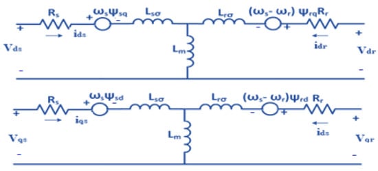
Figure 5.
DFIG equivalent circuit in dq synchronous reference frame.
2.2. Rotor Side Converter
The rotor side converter as shown in Figure 6 is used to control the rotor torque (or active power) and the reactive power of the DFIG. This is achieved through a vector control scheme. To implement this, the three-phase rotor currents are measured and converted to its dq axis model equivalent. The reference frame is aligned along the stator flux making calculations much easier and hence enhancing controllability. This alignment is done using a phase-locked loop. Once the d axis current (id) and q axis current (iq) are obtained they are fed to the PI controllers that make sure the id and iq values measured are equal to the reference or desirable values.

Figure 6.
Rotor Side Converter.
The reference values are obtained based on the formulae that relate the rotor dq currents to real power, reactive power as shown in Equation (1).
Stator active and reactive powers are,
2.3. Grid Side Converter
The grid side converter shown in Figure 7 is used to control the active and reactive power exchanged between the rotor and the grid. It controls the active power indirectly by maintaining the DC link voltage at a desired value. This is achieved by using a vector control scheme that manipulates grid currents and voltages of the DC link between the two converters. The three-phase grid currents are measured and converted to their respective dq model equivalent values. The dq reference frame is aligned to the grid voltage space vector resulting in simplified dq equations and hence improving control. The alignment is done using a phase locked loop whose reference is the three-phase grid voltages.

Figure 7.
Grid side converter.
Once this is achieved the measured d axis grid current and q axis grid current is given to the PI controller to make sure the measured value is equal to the reference value. Since the active power of the rotor has to flow through the DC link, by controlling the DC link voltage the active power is controlled. Therefore, the DC link voltage is regulated through a PI controller to obtain a constant, desirable voltage.
3. Vehicle to Grid System
A vehicle to grid system shown in Figure 8 is a unit in which the electric vehicle communicates with the grid by restituting electricity back to the grid. When fault occurs at the grid the deficiency of voltage occurring due to voltage sag will be compensated by the charging station via the bidirectional converter of the V2G unit. The V2G unit is primarily an EV charging station and is powered by a PV source. The voltage obtained from PV panel is fed to the battery through a boost converter and a bidirectional converter. The bidirectional converter controls the charging of battery from PV source as well as discharging the voltage back to grid when necessary. Under normal conditions the PV source charges the battery and on the occurrence of fault at grid the power flows backward wherein the battery discharges and supplies to the grid. The DC voltage from battery is fed to an inverter. The output of the inverter is integrated to that of grid to enable the fault ride through capability.

Figure 8.
Vehicle to grid system.
3.1. EV Charging Station Structure
The charging station structure depicted in Figure 9 mainly consists of bidirectional converters in which the energy can flow in both the directions of the converter. It is used as a pivotal device for linking the storage devices sandwiched by source and load in a hybrid system for continuous power flow. Bidirectional converter mainly regulates the output voltage by controlling the duty cycle of Pulse Width Modulated (PWM) controller with a certain frequency and duty ratio. By the variation of firing pulses, the buck and boost mode of bidirectional converter charges and discharges the battery in the EV charging station alternately. The voltage during the battery discharge is conditioned and tied to the grid to supplement the voltage sag due to fault. The control unit of charging station uses P&O MPPT controller to retrieve maximum power from the PV source and generates a duty cycle for PWM generator of DC–DC converter. Separate PI controllers are tuned to obtain duty cycles for the bidirectional converter. The reference voltage for the PWM controller for charging conditions is given by Equation (2). Similarly, the reference voltage for PWM controller for discharging condition is obtained by complementing the Equation (2).
where,
- = Reference voltage for PWM controller for charging condition
- = Reference voltage
- = DC–DC converter voltage
- = Reference current
- = Battery current
- = Proportional constant of the PI controller
- = Integral constant of the PI controller

Figure 9.
EV Charging station.
3.2. Voltage Tracking Unit
The voltage tracking unit shown in Figure 10 plays a very consequential role in determining the amount of voltage sag occurring due to fault. This unit creates a reference voltage for the PWM generator depending on the deficit voltage of the fault. Based on this reference voltage, PWM pulses are generated so that only required amount of voltage is imparted from the EV charging station to grid, to compensate the reduction in voltage caused due to a fault.

Figure 10.
Voltage tracking unit.
4. Modeling of DVR
DVR basically constitutes a DC power source, a converter and an injection transformer. The switching signals of the converter are generated using pulse width modulation technique. A Phase Locked Loop (PLL) in a synchronous reference frame (dq) is used to formulate the phase angle of the grid [14]. The DVR is connected to PCC in series with the grid, thereby injecting the voltage necessary for compensation to recover the voltage sag caused by the fault. Thus, DVR compensates for the voltage sag due to fault thereby protecting the grid from any potential damage.
The power delivered by the DVR is,
IL represents the RMS value of load current, represents the RMS value of the voltage injected,
The active power delivered by the DVR is,
where, ψ represents the phase angle. The angle is between the load voltage (VL) and load current (IL).
4.1. DVR Control Strategy
The DVR control scheme is depicted in Figure 11. This control scheme detects the fault from start-to-end of the event and controls the injected voltage as well. PLL generates the references of the load voltages which are used as the co-ordinates for the dq axes of the Fuzzy Logic Controller (FLC). During fault or disturbances, the voltage variation due to sag is compared with the nominal system voltage. This is mainly done to obtain the difference in voltage that the DVR has to inject in order to restore the voltage during fault. The compared voltages in dq reference frame as Vd and Vq is given as two inputs to the FLC. The FLCs ultimately provide the input signal to a PWM converter. The pulses from PWM converter controls the DVR, thereby giving only the necessary voltage that is needed for the voltage compensation during fault. The amplitude as well as the phase angle of the voltage injected can also be varied which allows the control and exchange of real power and reactive power exchange between the DVR and that of the grid.

Figure 11.
Control block diagram of DVR.
4.2. Fuzzy Logic Controller
The Fuzzy Logic Controller (FLC) is a control system in which the net output depends on the state of the input and the change in the state of the input. Since the original input and its corresponding variations at different states are taken into consideration unlike PI controller the output obtained is much precise in terms of the value of the voltage restored which is equal to the nominal value. In the proposed method two fuzzy logic controllers are used. One FLC is for the d-axis voltage and other FLC is for the q-axis of the voltage. An error signal is obtained from the original d and q components of stator voltage and a reference voltage of the corresponding axes as well as with DC link voltage. Hence there are two input membership functions one being the actual voltage and the other the error voltage in both direct and quadrature axes respectively.
Membership Functions
In both fuzzy controllers, there are eight input membership functions designated for error and three input membership functions designated for change in error. The output membership function varies from negative to very large positive with thirteen linguistic variables and is basically the control voltage given to PWM controller of the inverter. The membership functions for the inputs and output are indicated in Figure 12, Figure 13 and Figure 14 respectively. The membership functions of error voltage in d and q axes are Negative (N), Zero (Z), Very Small Positive (VSP), Small Medium Positive (SMP), Medium Positive (MP), Large Medium Positive (LMP), Large Positive (LP), and Very Large Positive (VLP). Similarly, the other input membership functions of change in error are Negative (N), Zero (Z), and Positive (P). The rule base for FLC is given in Table 1.

Figure 12.
Vde and Vqe- Input membership function of error.

Figure 13.
ΔVde and ΔVqe - Input membership function of change in error.

Figure 14.
Output membership function.

Table 1.
Rule base for fuzzy logic controller.
The control circuit for the DVR is shown in Figure 15. The three phase voltage from the grid is continuously tracked and converted to two phase using Park’s transformation and fed to two fuzzy controllers. The output from the fuzzy controllers are converted back to three phase using inverse Park’s transformation and fed as reference voltage to the PWM converter. Thus, the control unit controls the voltage produced by the DVR to compensate the voltage sag during fault.

Figure 15.
DVR control circuit.
5. Modes of Operation
5.1. Normal Mode
In this mode of operation as shown in Figure 16, the generated power from the hybrid PV/wind system is integrated with the grid. The DFIG based wind system generates AC voltage which is converted to DC using RSC. The converted voltage is stored in DC link capacitor. Concurrently, the PV source generates DC voltage whose maximum power is tracked using a MPPT controller. The obtained DC voltage from PV source is fed to a boost converter whose output is linked to the DC link capacitor. The DC link voltage is converted to AC via an inverter. The inverted AC output is integrated with the grid.

Figure 16.
Normal mode.
In an EV charging station the battery is charged by a separate PV source and continues to charge electric vehicles and the DVR stays idle in this mode of operation. Even though the output from EV charging station and DVR is bound to the grid, in this mode of operation the charging station or the DVR does not impact the grid integrated hybrid system. When the hybrid system encounters the fault, the charging station or the DVR takes over immediately depending on the intensity of the voltage sag thereby supplementing the shortfall voltage that is developed due to the fault.
5.2. Fault Ride through Mode
This mode of operation is called fault ride through mode as a fault is inculcated at PCC. During the event of fault, the hybrid system should stay connected to the grid as per the grid codes indicated in Figure 1. Within this short duration, the voltage sag due to fault should be compensated instantly to avoid the disconnection of wind and PV source. The shortfall of voltage is continuously tracked using a voltage tracking unit whose output is fed to control the pulses for the inverters of EV charging station and DVR respectively. Hence, in this mode either the battery of EV charging station discharges or the voltage is supplied by DVR, thereby compensating the deficit voltage depending on the intensity of the sag. The power flow for this mode of operation is shown in Figure 17. The V2G unit and the DVR is controlled using a switch depending on the intensity of the voltage sag. If voltage sag is between 0.9 to 0.51 p.u, the EV charging station provides voltage from battery which is fed to an inverter of appropriate ratings. The output of the inverter is connected to the grid so that the voltage compensation takes place effectively and rapidly when fault occurs. For voltage sag between 0.5 to 0.2 p.u, the DVR dominates in providing voltage compensation.

Figure 17.
Fault ride through mode.
6. Discussion of Simulation Results
The test system that is simulated using MATLAB Simulink is a hybrid wind/PV system with a 2.5 MW wind energy system and a 1 MW PV system connected to the grid. The system parameters used for the simulation of DFIG and PV are furnished in Table 2 and Table 3, respectively. The electric vehicle and DVR design parameters are listed in Table 4 and Table 5, respectively.
Table 2.
DFIG parameters.
Table 3.
PV panel parameters of hybrid system and electric vehicle.
Table 4.
Electric vehicle design parameters.
Table 5.
DVR parameters.
The EV charging station uses battery of rating 48V and 1000 Ah. The PV source ratings used in EV charging station is listed in Table 2. With the rating as specified, two batteries are connected in series whose discharge voltage can be obtained from a bidirectional converter. The bidirectional converter output acts as the input to the inverter which is tied to that of the grid. The wind power curve and the PV curve for the system is portrayed in Figure 18a,b, respectively.

Figure 18.
Characteristics of hybrid system: (a) wind power curve; (b) PV curve.
6.1. Low Voltage Ride Through
The attainment of LVRT with its compensation is determined for a balanced voltage sag for three phase, two phase and single-phase fault. Figure 19a indicates three phase symmetrical fault at grid. The voltage compensation for three phase fault using DVR and V2G is indicated in Figure 19b.

Figure 19.
(a) Three phase symmetrical fault. As it can be seen for all the faults, the voltage sag intensity is between 0.51 to 0.2 p.u for 2 to 2.2 s and between 0.9 to 0.5 p.u of nominal voltage for 3 to 3.2 s respectively. (b) Voltage compensation using DVR and V2G for three phase faults.
The intensity of the fault between 2 to 2.2 s is severe hence DVR provides voltage compensation. Similarly, the fault between 3 to 3.2 s has less intensity which can be compensated using V2G unit of electric vehicle. The two phase fault is depicted in Figure 20a and its corresponding voltage compensation by DVR and EV charging station is shown in Figure 20b. The fault occurs at 2 to 2.2 s and 3 to 3.2 s with different voltage sag intensity.

Figure 20.
(a) Two phase symmetrical fault; (b) voltage compensation using DVR and V2G for two phase faults.
Similarly, the single-phase fault with its voltage compensation is indicated in Figure 21. Figure 21a,b respectively shows single phase fault (Phase A) and its compensation using DVR and the battery discharge from EV.

Figure 21.
(a) Single phase symmetrical fault; (b) voltage compensation using DVR and V2G for single phase faults.
The current at PCC during various faults is indicated in Figure 22. During fault due to the sag in voltage in the faulty phases, the current shoots to a higher value than the nominal value. The sharp increase in the current during the event of various faults are shown in Figure 22a,c,e correspondingly for three phase, two phase and single-phase faults. The DVR and vehicle to grid compensation during fault brings the over shoot to the nominal value quickly as shown in Figure 22b,d,f.
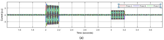
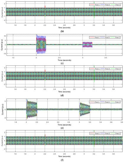
Figure 22.
Stator current: (a) three phase without compensation; (b) three phase with DVR and V2G compensation; (c) double phase without compensation; (d) double phase with DVR and V2G compensation; (e) single phase without compensation; (f) single phase with DVR and V2G compensation.
The active power dips at the instant of fault due to impending voltage sag. By fault ride through and corresponding voltage compensation the power is regulated to stay constant even during fault as shown in Figure 23.

Figure 23.
Active power with and without compensation for a wind speed 7 m/s and irradiance 400 W/m2.
The DC link voltage plays a very crucial role in providing a constant output voltage to the grid. When a fault occurs, owing to its associated voltage sag, there is a sudden drop in DC link voltage too. One of the other jobs of any voltage compensation network is to retain a steady DC link voltage. DVR and EV charging station as can be seen from Figure 24 maintains a steady DC link voltage irrespective of the intensity of the fault.

Figure 24.
DC link voltage with and without compensation.
6.2. EV Battery Charging and Discharging
The battery in the EV charging station will continue to charge from its own PV source during the normal operation of the hybrid system. When fault occurs, the battery automatically discharges to the grid to supplement the deficit of voltage occurring due to voltage sag. Figure 25 indicates the battery SOC and inverter voltage when fault occurs between the instant 3 to 3.2 s. It can be seen that the battery begins to discharge at exactly the instant of 3 s.

Figure 25.
Battery charging and discharging during normal mode and fault ride through mode.
6.3. DVR Output Voltage
Further the DVR is controlled in such a way that the voltage produced by the DVR supplies compensatory voltage only for the phase which is faulty. This is indicated in the Figure 26, where it can be seen that the DVR is switched on only at the instant of occurrence of high intensity fault between 2 to 2.2 s. In this paper predominance is given mainly to FRT capability, hence when fault occurs at grid, the EV charging station or the DVR restores the voltage to its nominal value based on the intensity of the voltage sag.

Figure 26.
DVR compensation voltage for 3 phases.
7. Conclusions
This paper deliberates the vehicle to grid communication and DVR in providing compensation in the event of grid fault in a hybrid PV/wind system. The vehicle-to-grid concept basically aims to supplement grid by turning electric cars into ‘virtual power plants’. In a grid integrated hybrid system, during the event of fault at PCC without any compensation, the DC link voltage and thereby the active power of the system drops down. The voltage compensation from vehicle to grid and DVR depending on the voltage sag intensity regulates the DC link voltage effectively and restores the active power effectively, amid the period of fault and maintains it as well. Depending on the crunch of the voltage during the fault, the battery in the electric vehicle charging station supplies the power controller coherently under different faulty conditions for different wind speeds as well as for variable irradiation. Thus, the V2G transmission is found to give credible voltage compensation and fault ride through during faults when the intensity of voltage sag is from 0.9 to 0.51 p.u. For voltage sag between 0.5 and 0.2 p.u, DVR takes over to provide voltage compensation for the continuous sustainability of the grid in the event of a fault.
Author Contributions
Conceptualization, U.R.; methodology, U.R.; software, U.R.; validation, U.R. and S.D.; formal analysis, U.R.; investigation, U.R.; resources, U.R.; data curation, U.R.; writing—original draft preparation, U.R.; writing—review and editing, S.D.; visualization, U.R.; supervision, S.D. All authors have read and agreed to the published version of the manuscript.
Funding
This research received no external funding.
Institutional Review Board Statement
Not applicable.
Informed Consent Statement
Not applicable.
Conflicts of Interest
The authors declare that they have no known competing financial interests or personal relationships that could have appeared to influence the work reported in this paper.
References
- Morshed, M.J.; Fekih, A. A novel fault ride through scheme for hybrid wind/pv power generation systems. IEEE Trans. Sustain. Energy 2019, 11, 2427–2436. [Google Scholar] [CrossRef]
- Saeed, M.A.; Khan, H.M.; Qureshi, S.A. Analyzing effectiveness of LVRT techniques for DFIG wind turbine system and implementation of hybrid combination with control schemes. Renew. Sustain. Energy Rev. 2017, 81, 2487–2501. [Google Scholar] [CrossRef]
- Moghadasi, A.; Sarwat, A.; Guerrero, J.M. A comprehensive review of low-voltage-ride-through methods for fixed-speed wind power generators. Renew. Sustain. Energy Rev. 2016, 55, 823–839. [Google Scholar] [CrossRef]
- Dösoglu, M.K.; Arsoy, A.B.; Güvenç, U. Application of STATCOM-supercapacitor for low-voltage ride-through capability in DFIG-based wind farm. Neural Comput. Appl. 2017, 28, 2665–2674. [Google Scholar] [CrossRef]
- Dösoglu, M.K.; Arsoy, A.B. Transient modelling and analysis of a DFIG based wind farm with supercapacitor energy storage. Int. J. Electr. Power Energy Syst. 2016, 78, 414–421. [Google Scholar] [CrossRef]
- Mahela, O.P.; Gupta, N.; Khosravy, M.; Patel, N. Comprehensive Overview of Low Voltage Ride Through Methods of Grid Integrated Wind Generator. IEEE Access 2019, 7, 99299–99326. [Google Scholar] [CrossRef]
- Hiremath, R.; Moger, T. Comprehensive review on low voltage ride through capability of wind turbine generators. Int. Trans. Electr. Energy Syst. 2020, 30, e12524. [Google Scholar] [CrossRef]
- Hu, S.; Lin, X.; Kang, Y.; Zou, X. An improved low-voltage ride through control strategy of doubly fed induction generator during grid faults. IEEE Trans. Power Electron. 2011, 26, 3653–3665. [Google Scholar] [CrossRef]
- Sivasankar, G.; Kumar, V.S. Improving stability of utility-tied wind generators using dynamic voltage restorer. J. Energy S. Afr. 2014, 25, 71–79. [Google Scholar] [CrossRef][Green Version]
- Hassanein, W.S.; Ahmed, M.M.; El-Raouf, M.O.A.; Ashmawy, M.G.; Mosaad, M.I. Performance improvement of off-grid hybrid renewable energy system using dynamic voltage restorer. Alex. Eng. J. 2020, 53, 1567–1581. [Google Scholar] [CrossRef]
- Xiao, S.; Yang, G.; Zhou, H.; Geng, H. An LVRT control strategy based on flux linkage tracking for DFIG-based Wind Energy Conversion System. IEEE Trans. Ind. Electron. 2013, 60, 2820–2832. [Google Scholar] [CrossRef]
- Molla, E.M.; Kuo, C. Voltage Quality Enhancement of Grid-Integrated PV System Using Battery-Based Dynamic Voltage Restorer. Energies 2020, 13, 5742. [Google Scholar] [CrossRef]
- Amalorpavaraj, R.A.J.; Kaliannan, P.; Padmanaban, S.; Subramaniam, U.; Ramachandaramurthy, V.K. Improved Fault Ride Through Capability in DFIG Based Wind Turbines Using Dynamic Voltage Restorer with Combined Feed-Forward and Feed-Back Control. IEEE Access 2017, 5, 20494–20503. [Google Scholar] [CrossRef]
- Shaaban, F.; Eajal, A.A.; El-Saadany, E.F. Coordinated charging of plug-in hybrid electric vehicles in smart hybrid AC/DC distribution systems. Renew. Energy 2015, 82, 92–99. [Google Scholar] [CrossRef]
- Ota, Y.; Taniguchi, H.; Nakajima, T.; Liyanage, K.M.; Baba, J.; Yokoyama, A. Autonomous Distributed V2G (Vehicle-to-Grid) Satisfying Scheduled Charging. IEEE Trans. Smart Grid 2012, 3, 559–564. [Google Scholar] [CrossRef]
- Brenna, M.; Foiadelli, F.; Leone, C.; Longo, M. Electric Vehicles charging Technology Review and Optimal Size Estimation. J. Electr. Eng. Technol. 2020, 15, 2539–2552. [Google Scholar] [CrossRef]
- Mehrjerdi, H.; Hemmati, R. Stochastic model for electric vehicle charging station integrated with wind energy. Sustain. Energy Technol. Assess. 2020, 37, 100577. [Google Scholar] [CrossRef]
- Mohammad, A.; Zamora, R.; Lie, T.T. Integration of Electric Vehicles in the Distribution Network: A Review of PV Based Electric Vehicle Modelling. Energies 2020, 13, 4541. [Google Scholar] [CrossRef]
- Chellaswamy, C.; Balaji, L.; Kaliraja, T. Renewable energy based automatic recharging mechanism for full electric vehicle. Eng. Sci. Technol. Int. J. 2019, 23, 555–564. [Google Scholar] [CrossRef]
- Verma, D.; Nema, S.; Shandilya, A.M. A Different Approach to Design Non-Isolated DC–DC Converters for Maximum Power Point Tracking in Solar Photovoltaic Systems. J. Circuits Syst. Comput. 2016, 25, 1630004. [Google Scholar] [CrossRef]
Publisher’s Note: MDPI stays neutral with regard to jurisdictional claims in published maps and institutional affiliations. |
© 2021 by the authors. Licensee MDPI, Basel, Switzerland. This article is an open access article distributed under the terms and conditions of the Creative Commons Attribution (CC BY) license (https://creativecommons.org/licenses/by/4.0/).