Abstract
The usage of splitter blades to enhance the performances of low specific speed pumps is common practice. Based on experimental and numerical studies, the influence of the addition of one and two splitter blades is investigated on a very low specific speed pump to assess their impact not only on the performance characteristics but also on the losses in all pump domains. First, the main characteristic curves are discussed and it is shown that the usage of splitter blades enhances the head of the pump while not impairing its efficiency. Secondly, a detailed analysis of the losses in the pump reveals that splitter blades improve the flow in all parts of the pumps, but the volute. The flow at the impeller outlet shows that splitter blades largely benefit the slip factor and discharges a more blade-congruent flow in the volute. However, higher absolute velocity at the outlet of the impeller with splitter blades increases friction at the volute wall, as confirmed by the average wall shear stress in the different tested cases.
1. Introduction
Pumps with a specific speed are called low specific speed (LSS) pumps. Their design presents many challenges. The most important is certainly related to their low efficiency, which is inherent to their design. At low specific speed, pumps provide high pressure at low flow rate. To achieve these performances, impellers have large diameters, causing an important part of the shaft power to be dissipated in the sidewall gaps of the pump due to disk friction [1,2]. These pumps are also prone to low-flow head instability, where a positive head slope at low-flow can be observed (). These phenomena are accentuated with lower specific speeds and commonly present at very low specific speed where .
Despite the certain constraints that LSS pumps suffer from, they have a wide range of applications, especially in the oil, gas, hydrocarbon [3,4] and even aerospace industry [5] and preferred to positive displacement pumps due to a simpler design, high speed operation and lower failure probability. The general performance and physical limitations of LSS pumps have been investigated by Kurokawa [6] and Olimstad [7]. Special design has also been proposed by Klas [8,9] where thick trailing edge replaced classic blading, or more recently by Wei [10] and Yang [11] who tested slit impeller blades on a pump with a specific speed . Nonetheless, the most common solutions for LSS pumps is the addition of splitter blades to the impeller, to raise the pressure developed by the impeller as extensively studied in references [12,13,14,15,16,17], where generally variations of a splitter blade position in the impeller passage is studied for pump optimization. Cui et al. [18] investigated experimentally and numerically a high-speed multi- blade impeller with a specific speed of . The initial impeller has four blades, and different splitter blades were added to have a total of 8, 16 and 24 blades. As the number of blades raises, the recirculation regions in the impeller are reduced, leading to a more uniform outlet flow. The efficiency improved with increased number of blades and the head becomes extremely flat, but stable, for the 24-bladed impeller. The head is higher for the 24-bladed impeller at partload, but at overload the 16-bladed impeller has a higher head.
Based on the summarized problematic of LSS pump operation, one of the best solutions is to consider the design of impeller with splitter blades. Therefore the motivation of this study is the detailed analysis of the influence of splitter blades on the performances of a very low specific speed pump. A 4-bladed impeller is used as a reference and the effect of the addition of one and two splitter blades per passage is investigated both numerically and experimentally. Thanks to a detailed CFD analysis, the study focuses on the influence of splitter blades on the power losses in each domain of the pump, on the flow at the outlet of the impeller and in the volute.
2. Geometry and Numerical Methods
2.1. Pump Model
The pump investigated in this paper is a water pump, and has a specific speed at the design point and an impeller diameter of 200 mm. The pump is scaled down from the original model, which is described and investigated by Klas in [8,9]. The geometry of the pump studied here differs from the referenced studies, as both the impeller and volute have been redesigned with an in-house code based on quasi-potential flow theory, presented in references [19,20]. The main pump parameters can be seen in Table 1.

Table 1.
Pump parameters.
The volute design is unconventional, as it does not respect the classic design rule of the conservation of angular momentum, or constant cross-sectional velocity. The area of the volute rapidly increases close to the throat area, and has a throat area too large for the design specific speed. This design choice has been made to ensure high performance of the pump at high-flow, and avoid a rapid head drop due to the choked flow at the volute throat. The consequence of this volute design over a classic design is a displacement of the Best Efficiency Point (BEP) to higher flow rates.
Three impellers are designed. The first impeller has 4 main blades. The second impeller has 8 total blades (4 main blades and 4 long splitters) and the third impeller has 12 total blades (4 main blades, 4 long splitters and 4 short splitters), see Figure 1 for the splitter leading edge position and Figure 2 for a visualization of the splitters in the impeller. The splitter blades follow the definition of the main blades (i.e., blade centerlines follow the same blade angle). The placement of the splitter blades follows design rules established by Yuan [13], which fixes the position of the leading edge of the splitter and its circumferential position in the passage. The long splitter is not located in the middle of the passage but displaced towards the suction side of the main blade. The short splitter is placed between the pressure side of the main blade and the suction side of the long splitter blade. Because the influence of splitter blades is of interest in this study, the three cases are labelled Case 0sp, Case 1sp and Case 2sp, respectively, for the case with zero, one and two additional splitter blades per impeller passage. The sidewall gaps have a constant thickness of 2 mm for the gap on the hub side and 3.125 mm for the gap on the shroud side.
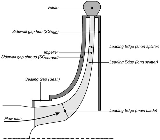
Figure 1.
Meridional section of the numerical domain.
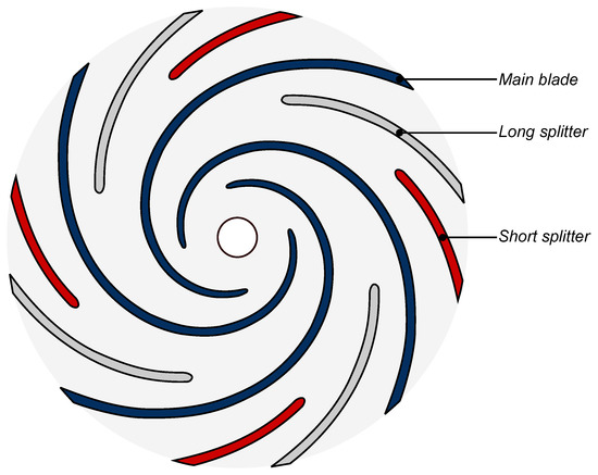
Figure 2.
Splitter blades position for the 3 studied cases.
2.2. Mesh and CFD Specification
The numerical simulation of low specific speed pumps can be problematic as thoroughly presented by Juckelandt [21] when using eddy-viscosity turbulence models. He showed that modeling the flow using the wall functions method may result in inaccurate performance predictions of these pumps at high flow rates. The reason lies in a detachment zone downstream the volute tongue responsible for large losses, which is not captured by the wall-functions. Resolving the boundary layer by using the Low–Reynolds number method allows to capture the physics of this phenomenon, but leads to a fine mesh near the wall as the criterion on the non-dimensional wall distance must be respected with an appropriate expansion ratio.
These guidelines have been applied in this study and the average value of at all walls is 1.3. This criteria is not respected at the trailing edge of the impeller where flow separation is evident.
The meshes of the different fluid domains are created using the pre-processor ICEM-HEXA 19.1. The cell count per domain and mesh quality metrics can be seen in Table 2, according to ICEM criteria.
Table 2.
Mesh metrics per computational domain.
The total cell count of each case is 15.4, 16.6 and 17.2 million cells for Case 0sp, Case 1sp and Case 2sp, respectively.
A grid convergence analysis is performed for the case Case 0sp to ensure that numerical results are independent of the grid. The torque , head H and and hydraulic efficiency are numerically evaluated. The results are shown in Figure 3 and the chosen grid in Figure 4. Each parameter is scaled by its final value (subscript f) obtained for the finer tested mesh.
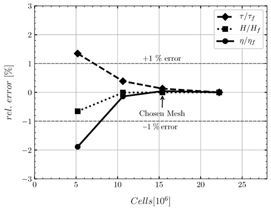
Figure 3.
Grid convergence analysis results for Case 0sp.
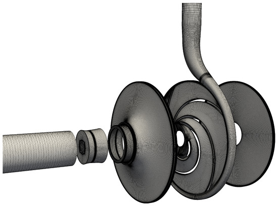
Figure 4.
View of the grid for Case 0sp.
ANSYS-CFX 19.1 is used to perform the computation. The turbulence model used is by Menter [22] with automatic wall-treatment. The curvature-correction option is set. Steady state simulations are used as initial conditions for transient simulations where the time step is fixed to of impeller rotation per time step, or s. The RMS residuals target is set to . The connection between the impeller and its neighbour is ensured with the Transient Rotor Stator interface. Stationary domains are connected with the General Grid Interface (GGI) boundary. The steady state behaviour of the pumps is of interest, thus all results and flow fields have been time-averaged over the last 5 impeller rotations, after a periodic behaviour is observed. Six flow rates are computed for each case, from to of the design flow rate. The boundary conditions were set to mass flow rate at the inlet and average static pressure at the outlet. The inlet surface is placed at a distance from the impeller inlet relative to the suction pipe diameter and the outlet is placed at a distance from the volute outlet relative to the discharge pipe diameter.
3. Validation
The validation of the numerical results is done for the three impellers. The impellers are 3D printed using the Fused Deposition Modeling (FDM) technology with Nylon 12. This method and material were used for a pump with comparable specific speed with higher performances by Olimstad [7]. The volute casing is CNC-milled from 2 blocks to ensure smooth hydraulic surfaces. The material used is Aluminium 5754, that has good corrosion resistance. A schematic diagram of the test rig can be seen in Figure 5 and a partial view of the physical test bench in operation in Figure 6. The inductive flow meter, torque transducer and pressure transducers, respectively, have errors of ±0.3%, ±0.2% and ±0.35% of the measured value.
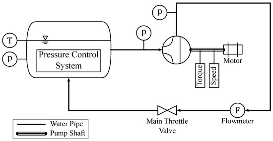
Figure 5.
Schematic diagram of the test rig.
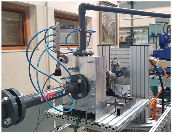
Figure 6.
Partial view of the test rig.
The steady state condition of the system was observed before recording a point of the characteristic curve. Each point is the result of averaging over 30 seconds with sampling frequency 2000 Hz.
The results for the head and the hydraulic efficiency are seen in Figure 7, Figure 8 and Figure 9 for Case 0sp, Case 1sp and Case 2sp, respectively. The standard deviation for each measurement is shown in the grey band. The results of the CFD computations are also presented on these figures.

Figure 7.
Head and efficiency as a function of the flow rate for Case 0sp.
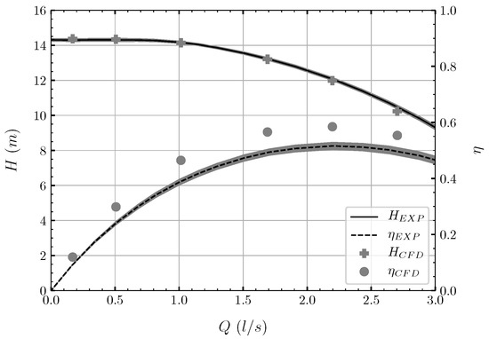
Figure 8.
Head and efficiency as a function of the flow rate for Case 1sp.
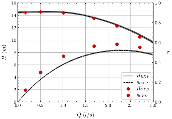
Figure 9.
Head and efficiency as a function of the flow rate for Case 2sp.
The experimental and numerical results are in good agreement for the head especially. For the hydraulic efficiency, a discrepancy is observed for all cases. The efficiency for all cases is similar and averages to 56% for the CFD and 50% for the experiment at the design point. The discrepancies in efficiencies may have several causes but the main one certainly resides in the fact that the impellers are 3D printed, and so their surface roughness influences the torque produced. It should also be noted that the hydraulic efficiency has been calculated by subtracting the static torque of the pump. The static torque has been measured by flooding the hydraulic circuit without impeller and by rotating the shaft at the rated speed. This way, the presented hydraulic efficiency does not include losses in the shaft seal and bearings.
Another interesting point is the standard deviation amplitude of the measured pressure, which is considerably reduced by the presence of splitter blades, indicating that the pressure and flow rate fluctuations decrease, providing a more stable flow delivery with lower pulsations.
4. Results and Discussion
Comments on the integral results (head, hydraulic efficiency) are based directly on the experimental values. Comments on flow features and loss analysis are based on CFD results. All results are time-averaged.
The integral results are plotted in Figure 10. They show that the head increases with the addition of splitters. At , the head coefficients relative to Case 0sp are and higher for Case 1sp and Case 2sp, respectively. The maximum hydraulic efficiency for each case is similar at , but is always located at higher flow rates than the design point. The BEP is located at values of , and for Case 0sp, Case 1sp and Case 2sp, respectively, showing that the introduction of splitters displaces the BEP to higher flow rates.
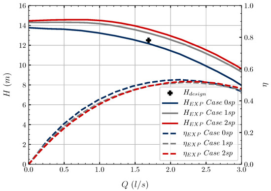
Figure 10.
Experimental results for the 3 tested impellers.
It is clear that the introduction of splitters in impeller passages has a negative impact on the stability of the head curve at low flow. The head is stable for Case 0sp, strictly flat for Case 1sp and raises slowly from the shut-off point for Case 2sp until . It should be noted that the numerical simulations were able to capture the slight head instability for the Case 2sp.
To better understand the influence of splitter blades on the pump performance, a power loss analysis is performed in each numerical domain. For a domain i, the formula to calculate the power loss is given by Equation (1).
is the power transferred to the fluid measured at rotating walls and measures the power entering and leaving a domain. Essentially, this formula is related to the total pressure loss in each numerical domain.
All losses are scaled by the shaft power at the design point for each respective case, to allow for a comparison of relative losses. The numerical domain investigated are the impeller, the volute and the sidewall gaps (shroud and hub side separately). The losses in the suction pipe are not considered.
First, the total relative losses are plotted as a function of the flow rate in Figure 11.
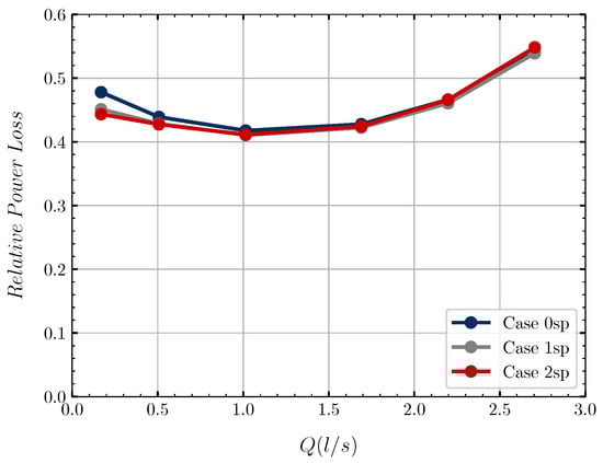
Figure 11.
Relative total losses.
At low flow, the relative losses are slightly higher for Case 0sp but very similar at design point and higher flow rates. This is expected as the hydraulic efficiency is similar for all cases. The detail of relative losses per domain can be seen in Figure 12. The impeller relative losses are similar over the whole range of flow rates. Despite the addition of splitter blades and absolute increase of power losses (skin friction of additional blades and shock loss at the leading edges), the impeller relative losses are not impacted. Gülich [23] suggests that the introduction of disruptive elements in the flow passages of low specific speed impellers implies virtually no loss due to the transfer of energy which is mostly centrifugal. The relative losses in the sidewall gaps (both hub and shroud side) are higher for Case 0sp. The losses in the gaps are mainly a function of the impeller diameter and the rotor speed, so the absolute losses for all cases are similar. Because Case 0sp develops less power (due to lower blade number), the relative power dissipation in the gaps is higher. The volute is the domain where Case 1sp and Case 2sp have significantly higher relative losses than Case 0sp. At the design point, the relative losses are 21% and 17% higher for Case 2sp and Case 1sp, respectively, compared to Case 0sp.
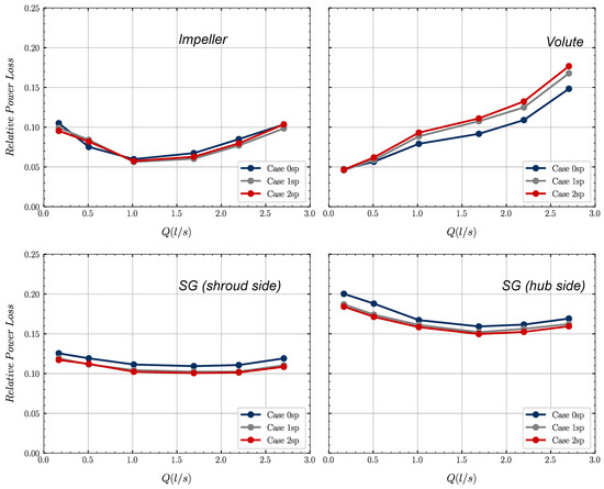
Figure 12.
Scaled relative losses per domain.
The reason for the increased volute losses is not straightforward, as the splitter blades’ role is also to provide a better flow guidance and output a more uniform flow into the volute. In fact, the main known effect of splitter blades on the impeller flow is the suppression of the jet-wake flow pattern. The reason for this pattern is a local eddy located on the pressure side of the blade and visualized in Figure 13, which represents the relative velocity in the impeller at the design point for all cases. There is a region with zero relative velocity, where the local eddy appears, for Case 0sp, and the introduction of splitter blades suppresses this eddy. More uniform values of the relative velocity are present in the impeller as a result. At the splitter blades’ leading edges, an acceleration of the relative velocity can be seen on the suction side, indicating that the blades are not aligned with the flow. Despite this fact, we saw that the relative impeller losses are not affected by the splitter blades.
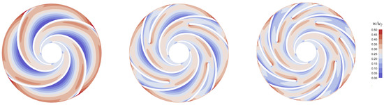
Figure 13.
Relative velocity comparison at design point.
An analysis of the flow at the outlet of the impeller allows to quantify the influence of the splitter blades on the flow entering the volute. Velocity components are extracted at using the post processor CFD-Post with a discretization of 0.5 degrees in the circumferential direction and 9 points in the spanwise direction totalling 6480 data points.
The slip factor , see Equation (2), is a parameter quantifying the deviation of the flow from the blade angles.
is the circumferential flow velocity at the impeller outlet obtained in a perfectly blade congruent flow, is the actual circumferential flow velocity and is the blade tip velocity. A value means a blade-congruent flow. Smaller values of means more deviation between flow and blade angles. The slip factor is plotted against the flow rate in Figure 14. It is clear that the introduction of splitter blades has a positive impact on the slip factor and that high values are obtained thanks to their presence. Values for Case 1sp and Case 2sp are up to 10% and 15% higher than Case 0sp at the design point.
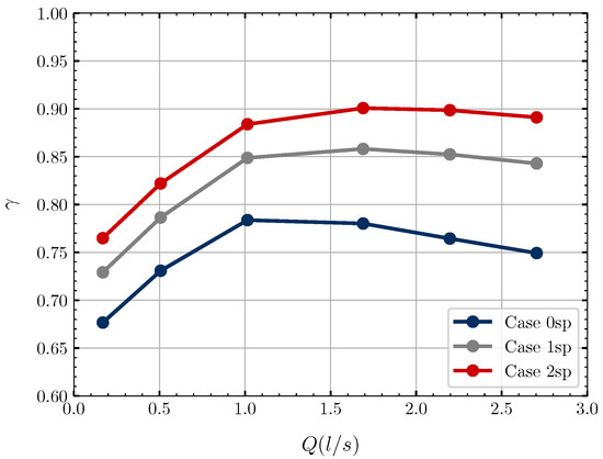
Figure 14.
Slip factor as a function of the flow coefficient.
Higher slip factors are a consequence of a higher circumferential velocity at the impeller outlet, which leads to a higher pump head based on the Euler equation of turbomachinery. However, the absolute velocity at the impeller outlet is also higher with the introduction of splitters, which leads to higher wall friction losses in the volute. This can be seen in the wall shear stress at the volute wall. Figure 15 represents the ratio of the wall shear stress on the volute wall between the Case 2sp and the Case 0sp. The wall friction is higher in the whole spiral section of the volute. Large ratio is observed in the diffusing part due to small values of the absolute wall shear stress in that region. On average, the wall shear stresses at the volute wall for Case 2sp and Case 1sp are 21% and 15% higher than Case 0sp. This fact explains the high power losses in the volute seen in Figure 12. Here, the benefit of the splitter blades in other domains are balanced with the friction in the volute domain.
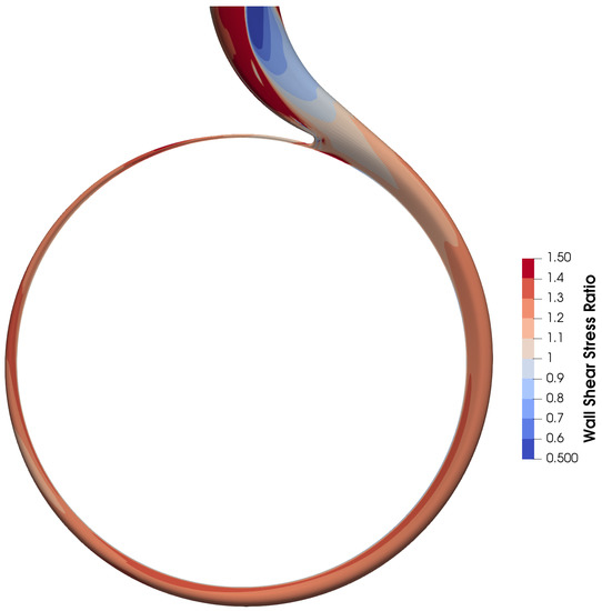
Figure 15.
Volute Wall Shear Stress ratio (Case 2sp relative to Case 0sp) at design point.
5. Conclusions
The study focuses on the influence of added splitter blades in the flow passages of a very low specific speed impeller. The main conclusion on the integral results is that the head is enhanced by splitter blades, the BEP is displaced to higher flow rates and the head curve stability is negatively influenced by the introduction of splitter blades. The maximum efficiency is almost unaffected by the introduction of splitters.
The enhanced pump performance is the consequence of an improved slip factor at the outlet of the impeller thanks to the presence of the splitter. The flow angle is more blade congruent.
The analysis of the losses in each domain of the pump leads to the conclusion that the introduction of splitter does slightly improve the flow in the impeller and sidewall gaps. The improved flow in the impeller leads to a higher absolute velocity at the impeller outlet which balances the benefits cited above with additional wall friction losses in the volute.
Nonetheless, the splitter blades have an overall beneficial effect as they enhance performances while not affecting the efficiency. The case with 2 splitter blades also displays advantages over the case with 1 splitter and suggests that increasing the number of splitters might be beneficial as skin friction and shock losses in the impeller are minimal, as displayed by the loss analysis. It is also suggested that impeller with splitter blades could be trimmed or designed with a lower diameter to attain the same head as Case 0sp. The diameter reduction may reduce power dissipation in the gaps and improve the overall pump efficiency.
Moreover, splitters seem to help with flow and pressure oscillations as briefly discussed with the reduced standard deviation from the experimental measurements. An analysis of the transient effects, e.g., pressure pulsations in the casing, radial and axial force oscillations, could help assessing more advantages of the splitter blades.
Author Contributions
Conceptualization, L.C. and P.R.; methodology, L.C. and P.R.; software, L.C. and D.Š.; validation, L.C. and D.Š.; investigation, L.C.; writing—original draft preparation, L.C.; writing—review and editing, P.R.; visualization, L.C.; supervision, P.R.; project administration, P.R.; funding acquisition, P.R. All authors have read and agreed to the published version of the manuscript.
Funding
This research was funded by project “Computer Simulations for Effective Low-Emission Energy Engineering” funded as project No. CZ.02.1.01/0.0/0.0/16_026/0008392 by Operational Program Research, Development and Education, Priority axis 1: Strengthening capacity for high-quality research and specific research project of FSI VUT No. FSI-S-20-6235.
Acknowledgments
Project “Computer Simulations for Effective Low-Emission Energy Engineering” No. CZ.02.1.01/0.0/0.0/16_026/0008392 by Operational Programme Research, Development and Education, Priority axis 1: Strengthening capacity for high-quality research and specific research project of FSI VUT No. FSI-S-20-6235 are gratefully acknowledged for support of the research.
Conflicts of Interest
The authors declare no conflict of interest.
Abbreviations
The following abbreviations are used in this manuscript:
| BEP | Best Efficiency Point |
| CFD | Computational Fluid Dynamics |
| CNC | Computer Numerical Control |
| FDM | Fused Deposition Modeling |
| GGI | General Grid Interface |
| H | Pump Head |
| LSS | Low Specific Speed |
| N | Rotor speed |
| P | Hydraulic Power |
| Q | Pump delivery flow rate |
| RMS | Root Mean Square |
| Impeller outlet width | |
| Absolute flow velocity at impeller outlet | |
| Theoretical circumferential flow velocity at impeller outlet | |
| Circumferential flow velocity at impeller outlet | |
| Impeller outlet diameter | |
| Mass flow rate | |
| Specific speed | |
| P | Power |
| Total pressure | |
| Volute wet surface | |
| Blade tip velocity | |
| w | Relative flow velocity |
| Impeller outlet width | |
| Hydraulic efficiency | |
| Slip factor | |
| Shaft torque | |
| Density | |
| Angular velocity | |
| Non dimensional wall distance |
References
- Zemanová, L.; Rudolf, P. Flow Inside the Sidewall Gaps of Hydraulic Machines: A Review. Energies 2020, 13, 6617. [Google Scholar] [CrossRef]
- Gülich, J. Disk friction losses of closed turbomachine impellers. Forsch. Ingenieurwes. 2003, 68, 87–95. [Google Scholar] [CrossRef]
- Benigni, H.; Jaberg, H.; Yeung, H.; Salisbury, T.; Berry, O. Numerical Simulation of Low Specific Speed API Pumps in Part-Load Operation and Comparison with Test Rig Results. J. Fluids Eng. 2018, 134, 024501. [Google Scholar] [CrossRef]
- Benigni, H.; Leithner, S.; Schiffer, J.; Jaberg, H.; Höller, S. Development of a novel centrifugal pump with lowest specific speed. In Proceedings of the International Rotating Equipment Conference, Düsseldorf, Germany, 14–15 September 2016; pp. 179–192. [Google Scholar]
- Schneider, S.; Veres, J.; Hah, C.; Nerone, A.; Cunningham, C.; Kraft, T.; Tavernelli, P.; Fraser, B. Satellite Propellant Pump Research. In Proceedings of the 41st AIAA/ASME/SAE/ASEE Joint Propulsion Conference & Exhibit, Tucson, Arizona, 10–13 July 2005. [Google Scholar] [CrossRef]
- Kurokawa, J.; Yamada, T.; Hiraga, H. Performance of low specific speed pumps. In Proceedings of the 11th Australasian Fluid Mechanics Conference, Tasmania, Australia, 14–18 December 1992; Volume 1, pp. 861–864. [Google Scholar]
- Olimstad, G.; Osvoll, M.; Finstad, P. Very Low Specific Speed Centrifugal Pump—Hydraulic Design and Physical Limitations. ASME. J. Fluids Eng. 2018, 140, 071403. [Google Scholar] [CrossRef]
- Klas, R.; Pochylý, F.; Rudolf, P. Analysis of novel low specific speed pump designs. IOP Conf. Ser. Earth Environ. Sci. 2014, 22, 012010. [Google Scholar] [CrossRef]
- Klas, R.; Pochylý, F.; Rudolf, P. Influence of recirculation on Y-Q characteristic curve of hydrodynamic pump. In Proceedings of the EPJ Web of Conferences; 2016; Volume 114, p. 02054. Available online: https://www.epj-conferences.org/articles/epjconf/abs/2016/09/epjconf_efm2016_02054/epjconf_efm2016_02054.html (accessed on 21 June 2021).
- Wei, Y.; Yang, Y.; Zhou, L.; Jiang, L.; Shi, W.; Huang, G. Influence of Impeller Gap Drainage Width on the Performance of Low Specific Speed Centrifugal Pump. J. Mar. Sci. Eng. 2021, 9, 106. [Google Scholar] [CrossRef]
- Yang, Y.; Zhou, L.; Zhou, H.; Lv, W.; Wang, J.; Shi, W.; He, Z. Optimal Design of Slit Impeller for Low Specific Speed Centrifugal Pump Based on Orthogonal Test. J. Mar. Sci. Eng. 2021, 9, 121. [Google Scholar] [CrossRef]
- Miyamoto, H.; Nakashima, Y.; Ohba, H. Effects of Splitter Blades on the Flows and Characteristics in Centrifugal Impellers. JSME Int. J. 1992, 35, 238–246. [Google Scholar] [CrossRef]
- Yuan, S.; Zhang, J.; Tang, Y.; Yuan, J.; Fu, Y. Research on the Design Method of the Centrifugal Pump With Splitter Blades. FEDSM 2009, 1, 107–120. [Google Scholar] [CrossRef]
- Zhang, Y.; Yuan, S.; Zhang, J.; Feng, Y.; Lu, J. Numerical investigation of the effects of splitter blades on the cavitation performance of a centrifugal pump. IOP Conf. Ser. Earth Environ. Sci. 2014, 22, 052003. [Google Scholar] [CrossRef]
- Ye, L.; Yuan, S.; Zhang, J.; Yuan, Y. Effects of Splitter Blades on the Unsteady Flow of a Centrifugal Pump. In Proceedings of the Fluids Engineering Division Summer Meeting. American Society of Mechanical Engineers, Rio Grande, PR, USA, 8–12 July 2012; pp. 435–441. [Google Scholar] [CrossRef]
- Zhang, J.; Li, G.; Mao, J.; Yuan, S.; Qu, Y.; Jia, J. Effects of the outlet position of splitter blade on the flow characteristics in low-specific-speed centrifugal pump. Adv. Mech. Eng. 2018, 10. [Google Scholar] [CrossRef]
- Gu, Y.; Yuan, S.; Pei, J.; Zhang, J.; Zhang, F.; Huang, X. Effects of the impeller-volute interaction on the internal flow in a low-specific-speed centrifugal pump with splitter blades. Proc. Inst. Mech. Eng. Part A J. Power Energy 2017, 232, 170–180. [Google Scholar] [CrossRef]
- Cui, B.; Zhu, Z.; Zhang, J.; Chen, Y. The Flow Simulation and Experimental Study of Low-Specific-Speed High-Speed Complex Centrifugal Impellers. Chin. J. Chem. Eng. 2006, 14, 435–441. [Google Scholar] [CrossRef]
- Pochylý, F.; Stejskal, J. Rotational Flow in Centrifugal Pump Meridian Using Curvilinear Coordinates. J. Fluids Eng. 2016, 138, 081101. [Google Scholar] [CrossRef]
- Stejskal, J. Analysis of the Velocity and Pressure Fields of the Liquid Using Curvilinear Coordinates. Ph.D. Thesis, Brno University of Technology, Brno, Czech Republic, 2017. [Google Scholar]
- Juckelandt, K.; Wurm, F.H. Applicability of wall-function approach in simulations of turbomachines. In Proceedings of the ASME Turbo Expo 2015: Turbine Technical Conference and Exposition, Montreal, QC, Canada, 15–19 June 2015; Volume 2B, p. GT2015-42014. [Google Scholar] [CrossRef]
- Menter, F.R. Two-Equation Eddy-Viscosity Turbulence Models for Engineering Applications. AIAA J. 1994, 32, 1598–1605. [Google Scholar] [CrossRef]
- Gülich, J. Centrif Pumps; Springer: Berlin/Heidelberg, Germany, 2014. [Google Scholar]
Publisher’s Note: MDPI stays neutral with regard to jurisdictional claims in published maps and institutional affiliations. |
© 2021 by the authors. Licensee MDPI, Basel, Switzerland. This article is an open access article distributed under the terms and conditions of the Creative Commons Attribution (CC BY) license (https://creativecommons.org/licenses/by/4.0/).