1. Introduction
Gob-side entry retaining is one of the most commonly used mining method in non-pillar coal mining. In this method, the former entry is artificially retained as the tailgate for the next mining panel by constructing a filling wall made of concrete blocks, pigsties, high-water packing material, and other fill materials, which can greatly improve resource recovery and reduce roadway drivage rate [
1,
2]. However, in case of complex geological mining engineering, the conventional gob-side entry retaining method encounters inevitable difficulties, due to high stress, high dynamic disturbance and large deformation issues [
3,
4,
5]. Furthermore, the high cost of filling materials and time-consuming have also severely restricted the wide application of the conventional gob-side entry retaining method.
In order to address the problems encountered in conventional gob-side entry retaining method, an innovative gob-side entry retaining method formed by roof fracturing (GERRF) is proposed [
6,
7]. In this method, a pre-fracturing is constructed in the gob-side immediate roof before mining activities. If without roof fracturing, the entry roof is connected to the gob roof, and their movements are closely associated, as shown in
Figure 1a. After roof fracturing, the pre-fracturing interdicts the stress propagation from the gob roof to entry roof. Additionally, making the immediate roof cave smoothly under the action of weighting and break into crushed rocks of various sizes. Then, the crushed rocks are efficiently used to support and control the movement of gob roof [
8,
9], which make the GERRF method more flexible and effective. Besides, the conventional cables are difficult to adapt to the large deformation of entry for its insufficient deformability. So the constant resistance and large deformation cables (CRLD cables) with excellent deformability are used to strengthen the entry roof in the GERRF method, which can mitigate the deformation and release some deformation energy of the surrounding rock. In addition, the entry-in support such as hydraulic props and pier-beam unit supports are collectively used to strengthen the entry roof [
10,
11,
12], as shown in
Figure 1b.
The crushed rocks are the maintenance body for the GERRF method, its compression and deformation characteristics appear to be very important on the stability of the retained entry. Much research has been focused on the instantaneous compressible deformation [
13,
14,
15] and creep deformation [
16,
17,
18] of crushed rocks by uniaxial compression test. However, in these uniaxial compression tests, the crushed rocks were completely constrained on all sides, the boundary conditions were significantly different from the GERRF method [
19,
20]. Therefore, an innovative experimental device to simulate the boundary condition of crushed rocks in gob area of GERRF was developed. Using the device, the compression tests of crushed mudstones with different particle sizes were carried out. In the tests, the deformation behavior of crushed mudstones with different particle sizes in GERRF method was studied, together with that of the lateral stress giving rise to lateral deformation of support structure was measured, which expects to provide experimental evidence for deformation prediction and supporting design of the GERRF method.
2. An Innovative Experimental Device
In the previous research data obtained from uniaxial compression tests, crushed rocks achieved a greater compactness under axial stress. However, the crushed rocks in the GERRF method are difficult to compact tightly, but rather acquire a new equilibrium state with the surrounding rock. Therefore, an innovative experimental device simulated the geometric structure of the GERRF method was developed, as shown in
Figure 2. The experimental device comprises of a loading plate, a cubic frame containing and a base plate. The internal dimensions of the device are 400 mm × 400 mm × 400 mm. Three of the vertical sides of cube are fabricated with Q235 solid steel, while the other side is the simulated surface of gangue rib, which comprises of high-strength wire mesh and scaled down support bars. In accordance with the adopted geometrical similarity ratio of 1:10, the dimensions of the scaled down support bar are 440 mm in height, 10 mm in width and 5 mm in thickness. A total of eight scaled down support bars are arranged on the simulation surface of gangue rib. The arrangement spacing is about 55–56 mm.
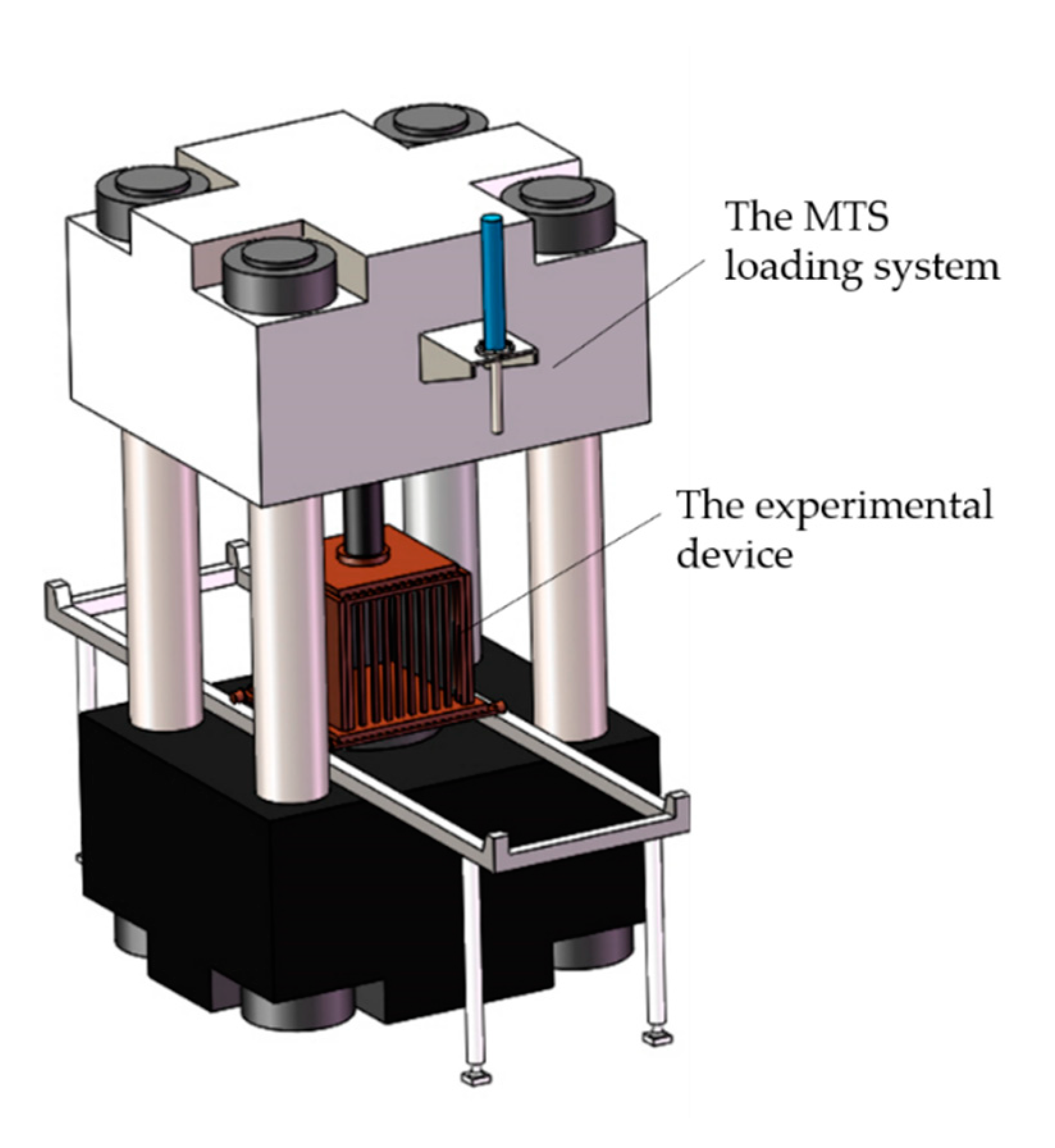
The MTS hydraulic servo loading system used in this study is illustrated in
Figure 3. The maximum axial load of the triaxial loading system is 2000 kN, and the accuracy of the measurement of axial load is less than 0.01 kN.
3. Experimental Materials and Methods
3.1. Crushed Rock Samples
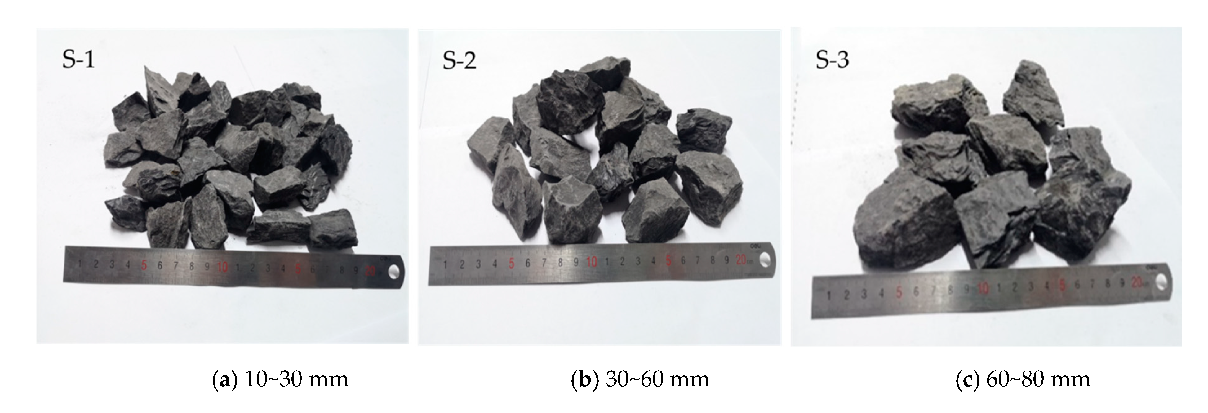
The crushed rock samples used in the tests were the crushed mudstones obtained from the gob roof of 12201 working face in the Haragou Coal Mine (Shenmu, China). The natural density and the uniaxial compressive strength of the crushed rock samples were 2.65 g/cm
3 and 19.8 MPa respectively. In accordance with the need to comply with acceptable size of the particles of crushed rocks in reliable testing, a ratio of 1/5 between the inscribed circle diameter (
D) of cubic container [
21], the largest crushed rock particles had to be maintained. Therefore, the maximum particle size of samples used in tests was limited to 80 mm. Three types of crushed mudstone samples with different ranges of particle size categories (10~30, 30~60, 60~80 mm) were prepared for the tests, as shown in
Figure 4.
3.2. Lateral Stress Monitoring Plan
To monitor the lateral stress exerted by the crushed rocks on the support structure of gangue rib during the tests, strain gauges were affixed on the scaled down support bars of the simulation surface of gangue rib. In consideration that a certain amount of deformation space was needed to be provided for the axial compression of the crushed mudstones, the strain gauges were so affixed evenly within 230 mm in the vertical direction, as shown in
Figure 5.
3.3. Loading Scheme
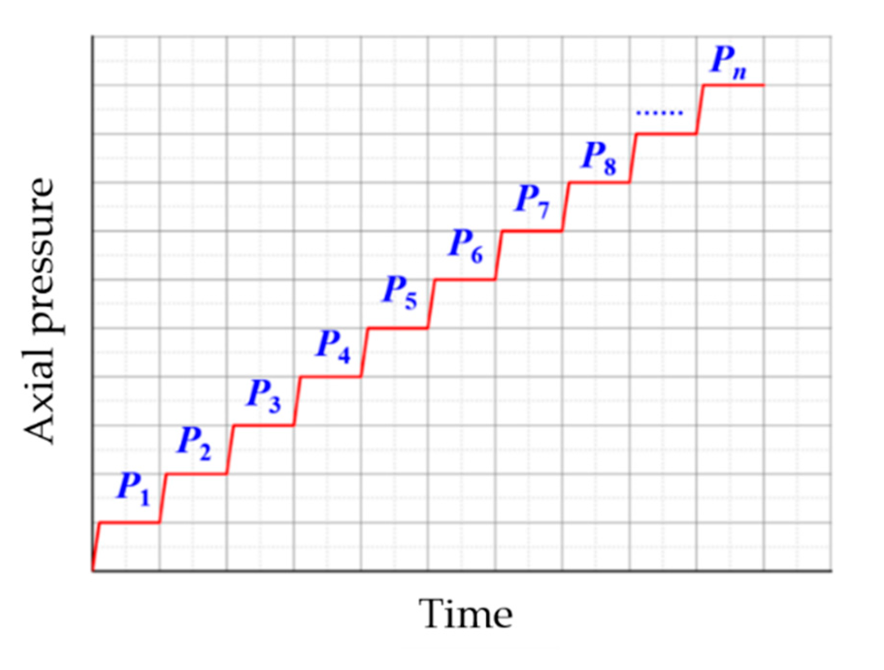
Assuming that the roof pressure acting on the crushed rocks in the gob area remains unchanged during the two caving activities of roof strata, it was considered necessary that the axial pressure acting on the crushed rocks in the gob area to be increased in a stepped manner [
22]. Thus, the tests were conducted under incremental loading as shown in
Figure 6. In GERRF method, the support structures of gangue rib deformed in response to lateral stress generated by crushed rocks in gob side. In engineering practice, the support structures of gangue rib are not allowed to produce large deformations. So, in the tests, the maximum axial pressure was set at a value corresponding to when the support structure will begin to deform, which was set as 1.5 MPa according to preliminary experiments results. In order to observe the periodic deformation behavior of crushed rocks in greater detail, the loading increment Δ
P was designed as 0.15 MPa.
3.4. Experimental Procedure
The height of the crushed mudstone samples was set to 380 mm before the initiation of the compression tests. The experimental procedures are described as follows:
Fixed the strain gauges on the inner wall of the support bars.
Placed the crushed mudstone rocks in cubic container layer by layer, ensuring that the samples were mixed thoroughly. After the height of the samples reaches the target height of 380 mm, the loading plate was assembled and the experimental device was prepared to loaded.
An initial preload of 20 kN was applied prior to the first compression stage, in order to be rid of any large voids that would still be present in the sample.
Then the axial loading program was commenced. The axial loading at each stage was completed in 30 s. After the target axial load at each stage was reached, the target stage load was maintained for 10 min before the next loading stage. The loading sequence was terminated when the supporting structure of gangue rib began to deform.
4. Experimental Results
4.1. Axial Deformation
4.1.1. Accumulated Axial Deformation
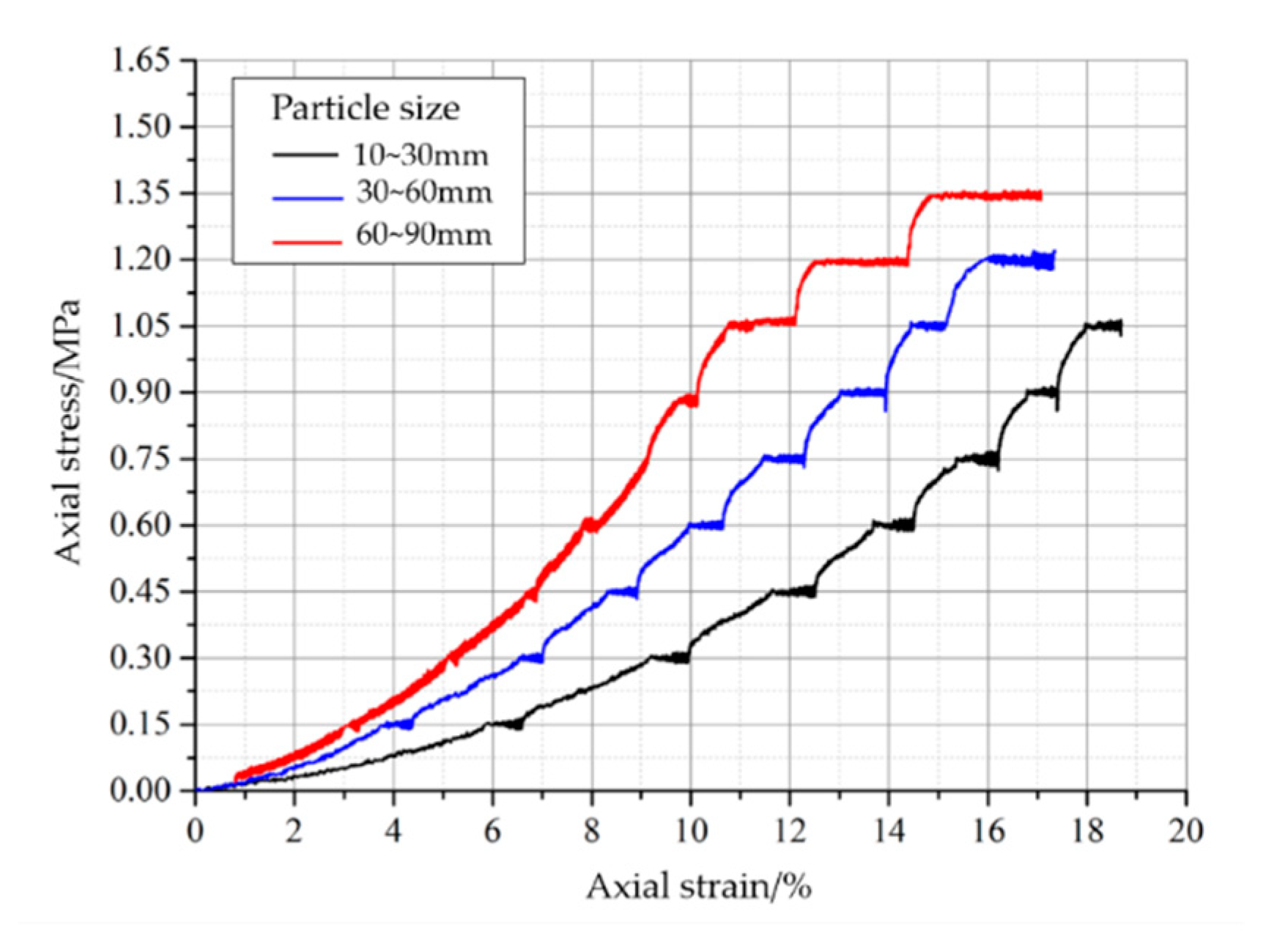
The stress-strain curves of the crushed mudstone samples for the entire loading process under the incremental loading were recorded in
Figure 7. The figure clearly shows that the accumulated axial strain of the crushed mudstone samples increased with increasing axial stress. It can be seen that the accumulated axial strain of S-1, S-2, and S-3 were 14.5%, 10.64%, and 8% respectively when the axial stress
P = 0.6 MPa (the fourth loading stage); When the axial stress
P = 0.9 MPa (the sixth loading stage), the accumulated axial strain of S-1, S-2, and S-3 were 17.4%,13.93% and 10.1%. These results indicate that the accumulated axial strain of the samples decreased with increasing particle size under the same axial stress. Additionally, it was noted that the ultimate loading stage for S-1, S-2, S-3 was the 7th, 8th and 9th stage, respectively, which demonstrated that the lateral stress generated on the support structure by the crushed mudstones decreased as the particle size increased under the same axial stress as well. This conclusion will be explained precisely in
Section 4.2.
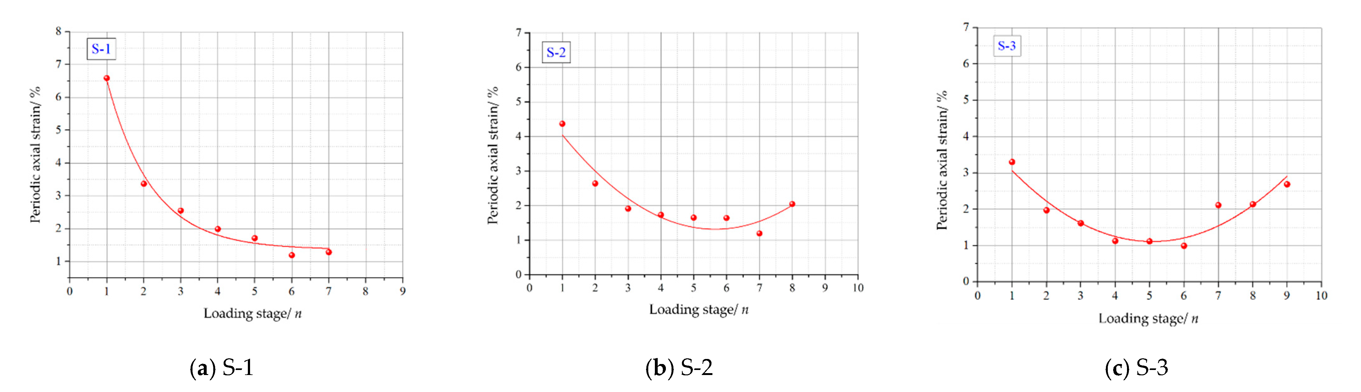
4.1.2. Periodic Axial Deformation
Figure 8 shows the change rule of axial strain increment corresponding to each loading stage (periodic axial stain) for S-1, S-2 and S-3. And the periodic axial stain values of each loading stage are listed in
Table 1. For sample S-1 (
Figure 8a), the periodic axial stain decreased with the loading stage increasing; In the case of samples S-2 and S-3, the periodic axial strain showed a decreasing trend in the early loading stages, but rebounded in the later loading stages, as seen in
Figure 8b,c. This results indicated that there was a skeletal load-bearing effect in large-sized rushed mudstone samples (S-2, S-3).
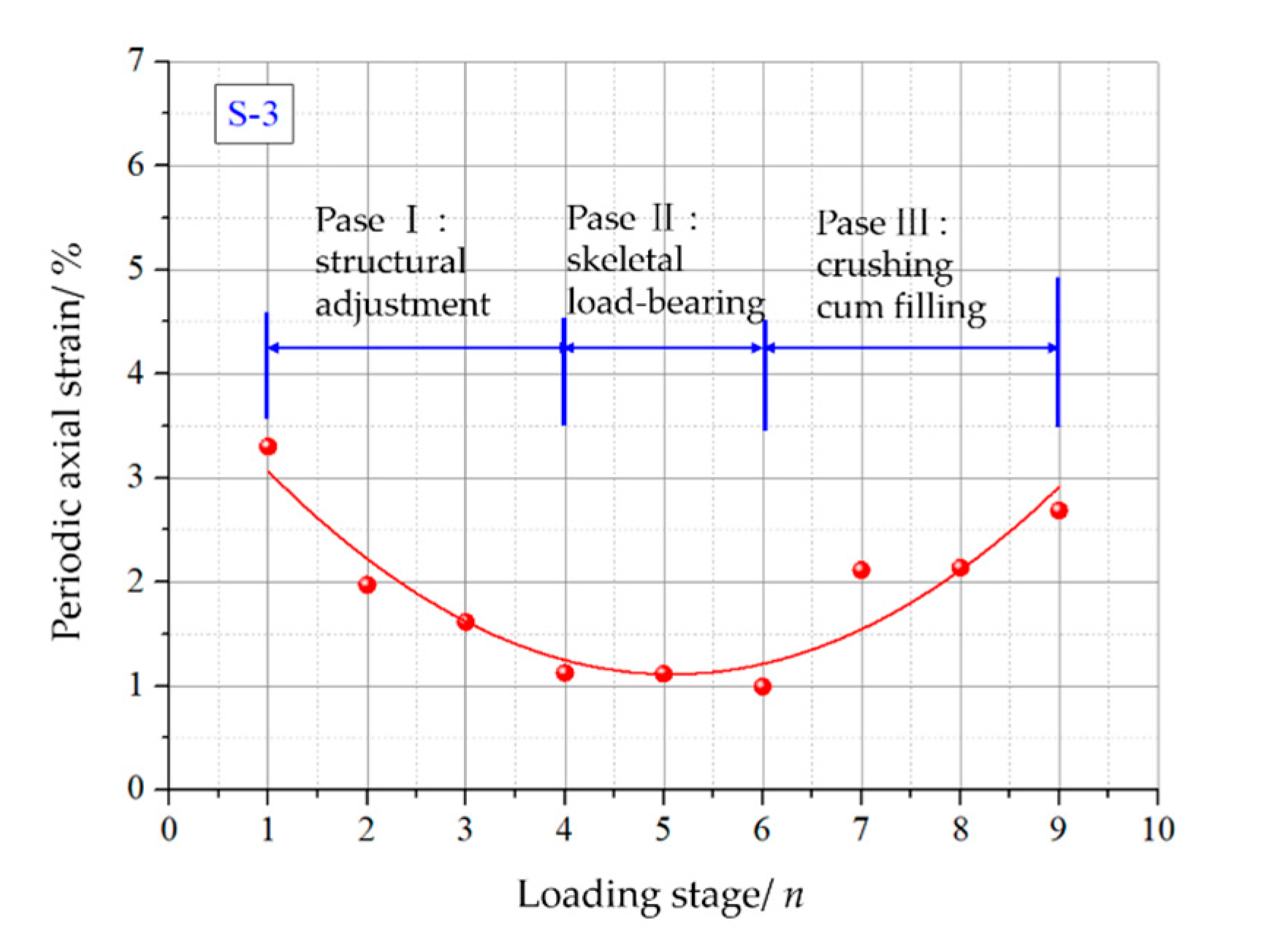
For crushed mudstone sample S-2 and S-3, the entire deformation process can be divided into structural adjustment, skeleton load-bearing and crushing cum filling phases, as presented in
Figure 9. In the skeleton load-bearing phase, the periodic axial strain was relatively smaller, which indicated that the crushed rocks with large-sized particles have higher deformation resistance and stability in the skeleton load-bearing phase than other phases.
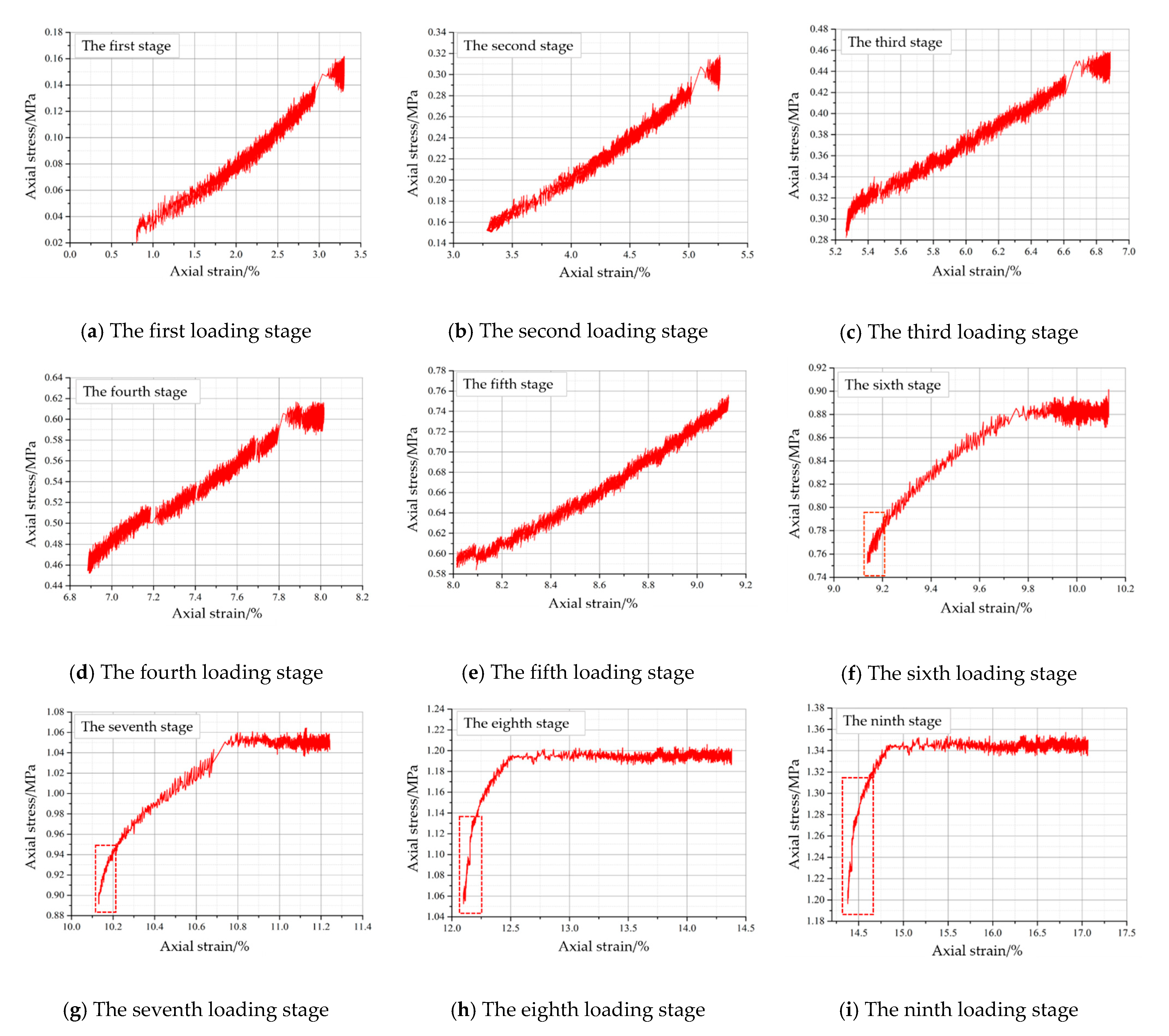
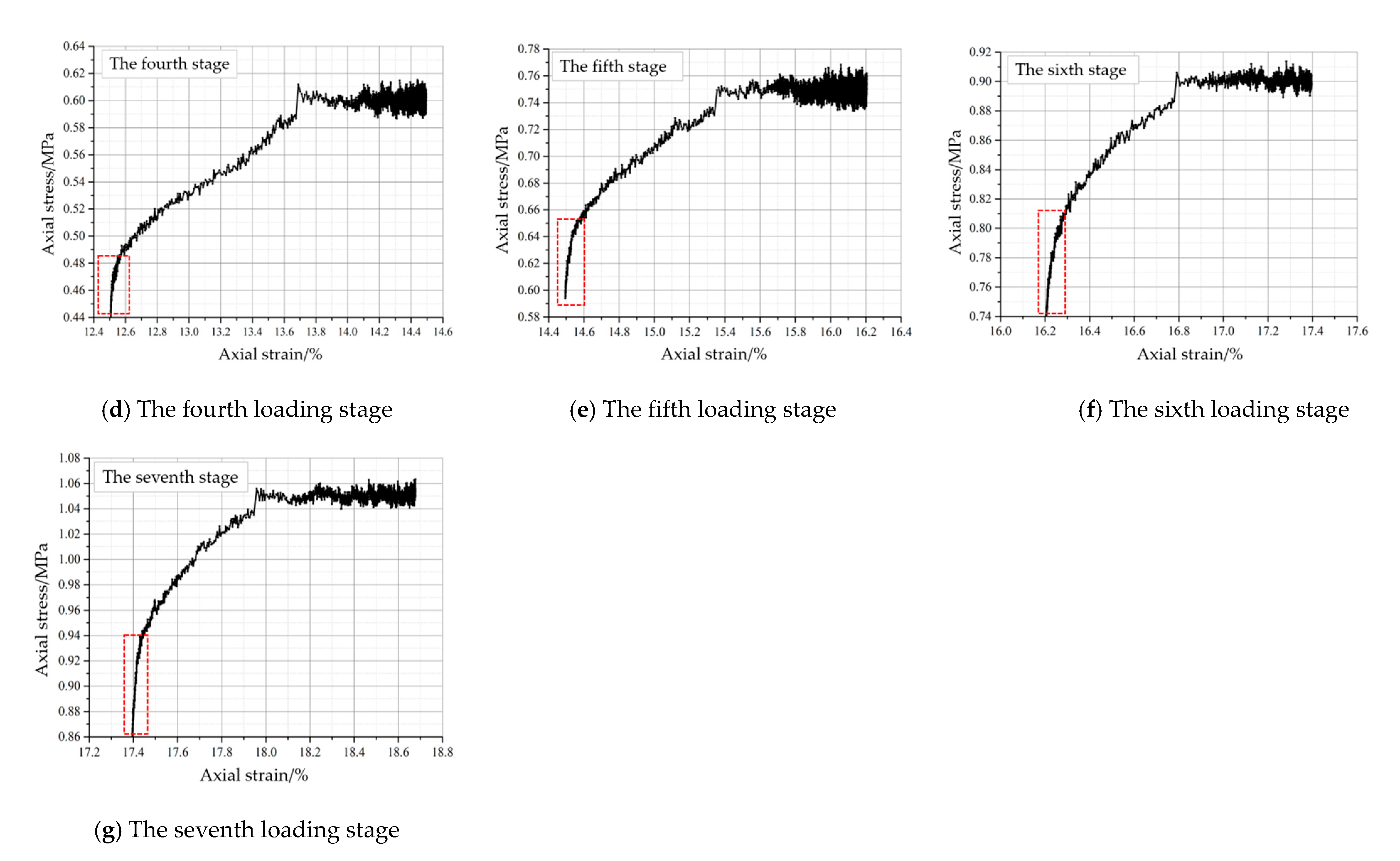
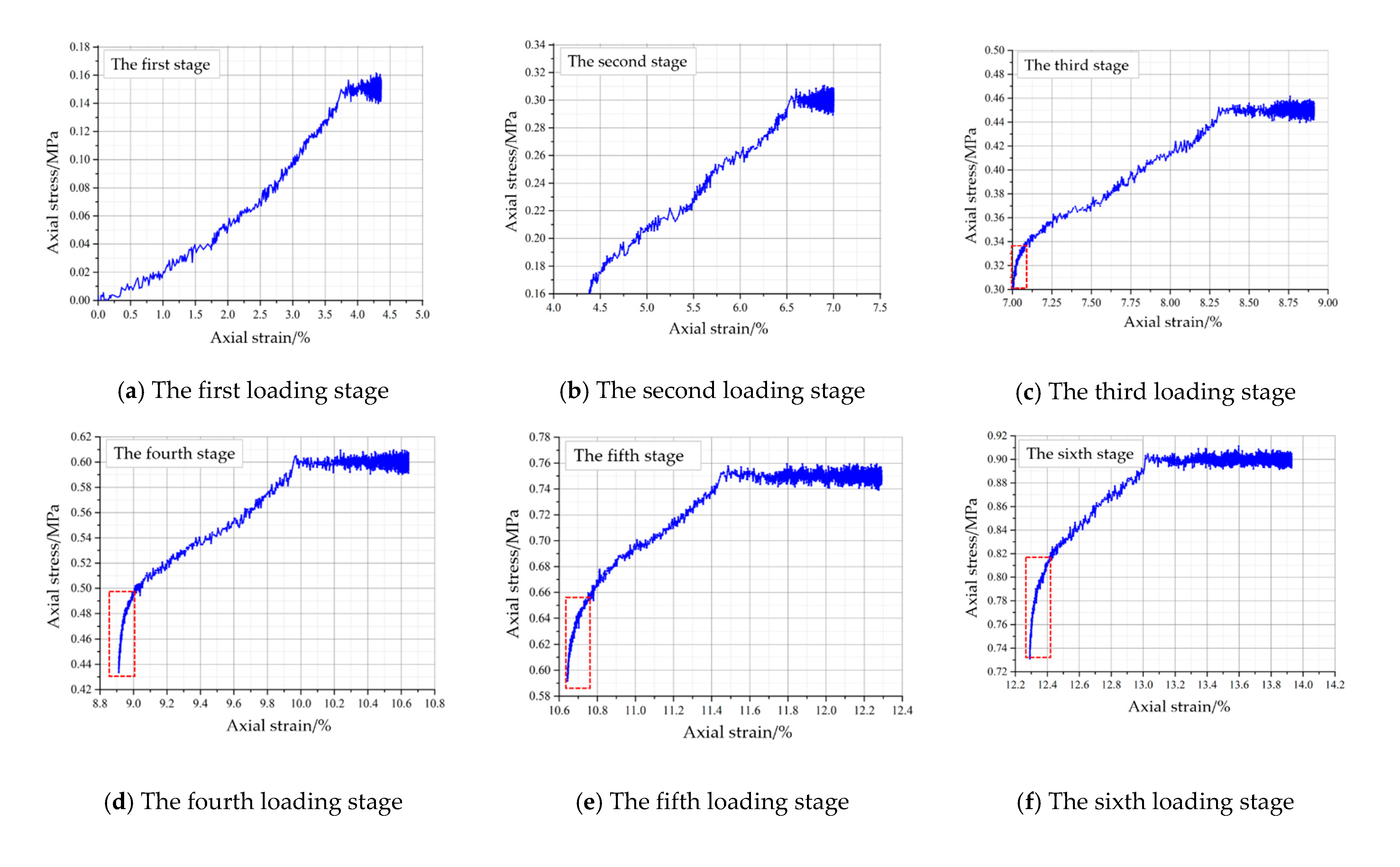
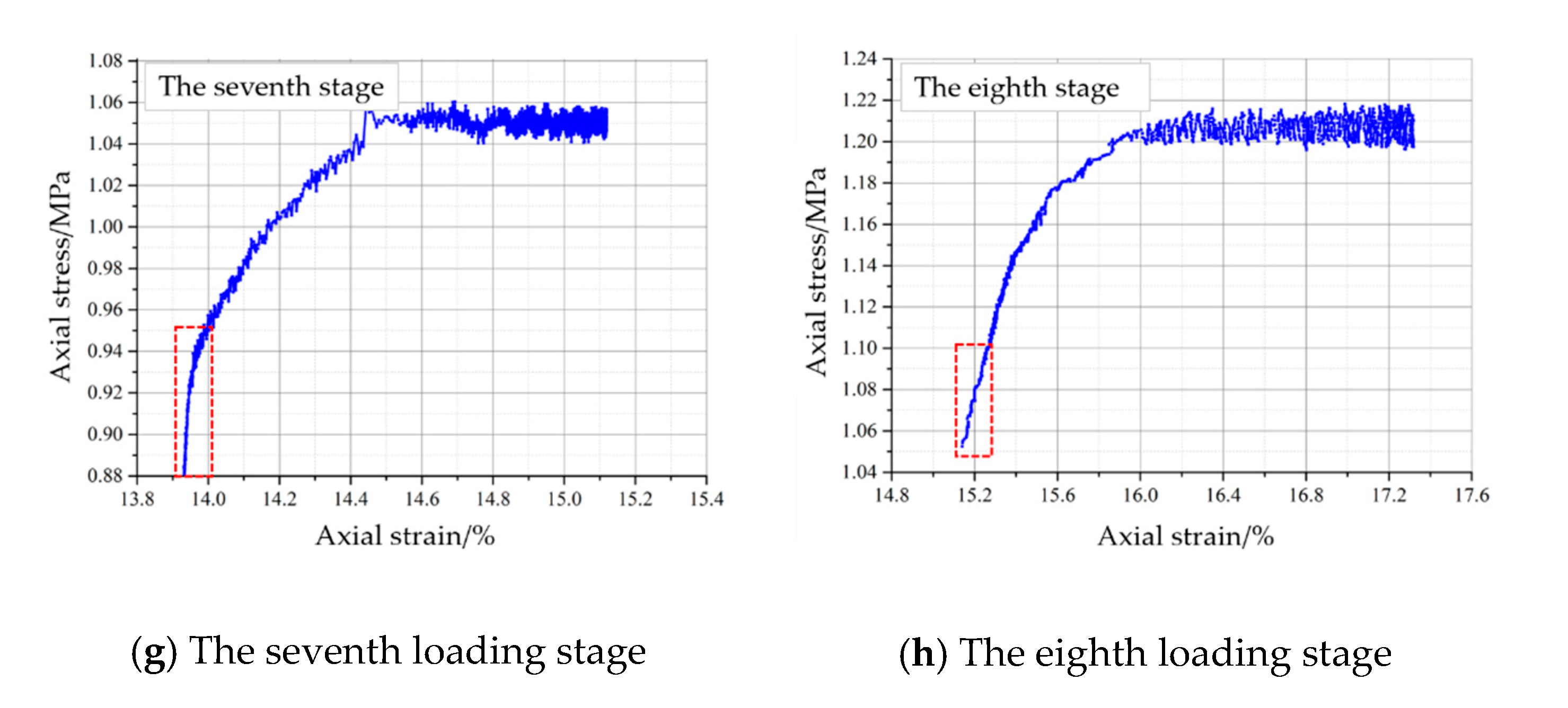
The periodic axial stress-strain curves of the crushed mudstone samples at each loading stage were presented in
Figure 10,
Figure 11 and
Figure 12. From these figures, we known that the periodic axial strain of the crushed mudstones was composed of instantaneous deformation and creep deformation. Observations of the instantaneous axial strain and axial creep strain of crushed mudstones at each loading stage were listed in
Table 2 and
Table 3 respectively.
Table 2 showed that the instantaneous axial strain of all samples decreased with increasing loading stage. From observations in
Table 3, we know that the axial creep strain of sample S-1 at each loading stage was approximately similar, and most of them were between 0.7–0.8. But for sample S-2 and S-3, the axial creep strain was a minimum at the skeletal load-bearing stage. As it entered the crushing cum filling stage, the periodic creep deformation increased sharply.
In addition, two types of periodic stress-strain curves were observed from the test results, which were “down-concave” type and “upper-convex” type, respectively. The “down-concave” type stress-strain curve appeared at the previous loading stages, which presented a large growth rate of axial strain at the earlier phases of the loading stage, and a smaller growth rate at the later phases of the loading stage. Conversely, for the “upper-concave type” stress-strain curve, the growth rate of axial strain at earlier phases of the loading stage was small (shown within a red colored frame in
Figure 10,
Figure 11 and
Figure 12). But after the axial stress reached a certain value, the axial strain increased continuously.
4.2. Lateral Stress
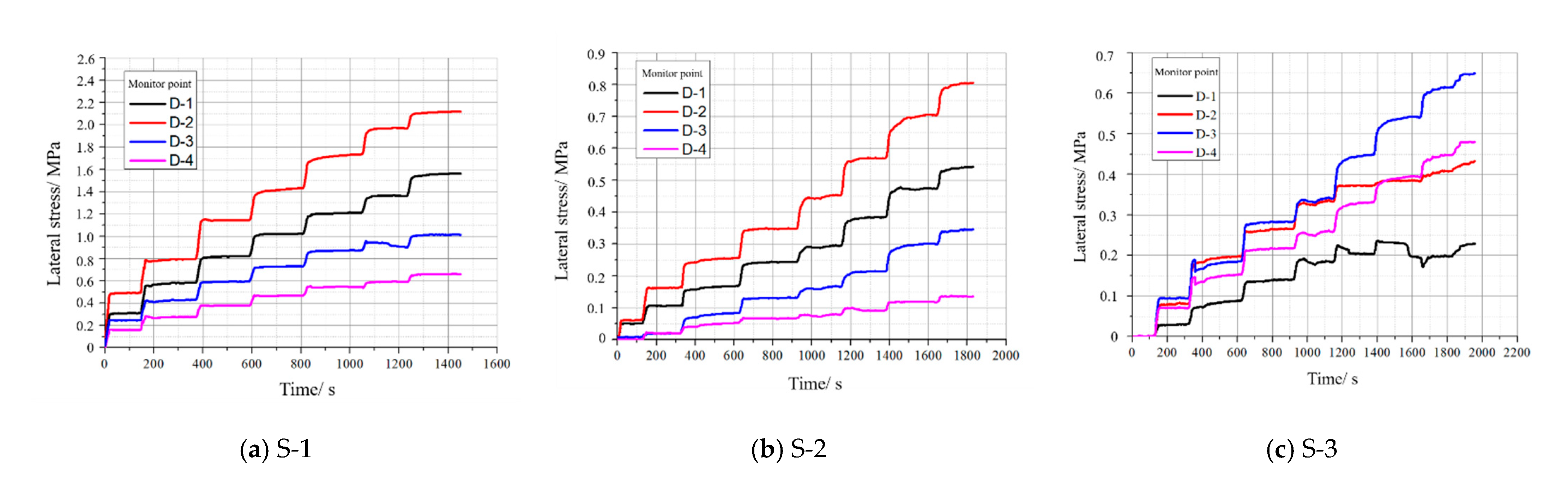
Figure 13 shows the lateral stress of the D column monitoring points on the simulated support structure in the tests. From the results, it can be seen that the lateral stress increased as the axial stress increased. With the increase of particle size, the lateral stress generated on the support structure decreases under the same axial stress. In addition, the test results showed that the lateral stress generated by the sample S-1 and S-2 consistently showed a better regularity than sample S-3.
Using a curve fitting analysis, a linear relationship between the lateral stress generated by crushed mudstone rocks and the axial stress can be represented by the following equation:
where
σx is the lateral stress from the crushed mudstones that was generated on the support structure;
σy is the axial stress applied on crushed mudstones;
a and
b are regression coefficients. The regression coefficients established for all the tests are itemized in
Table 4. The most of correlation coefficients are greater than 0.95.
5. Discussion
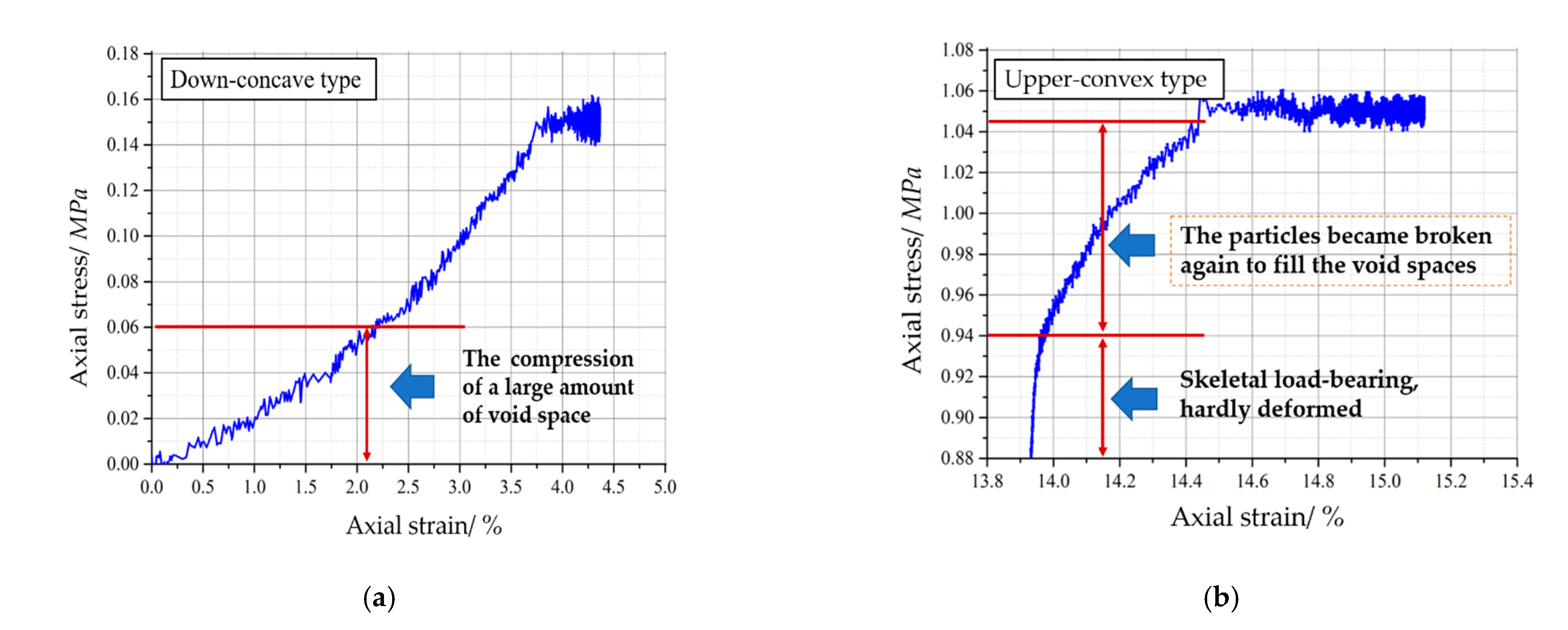
The reasons for deformation of the crushed rocks include void space compression, particle crushing and particle splitting. The different types of periodic stress-strain curves represented different deformation mechanisms for crushed mudstones. As shown in
Figure 14a, for “down-concave type” stress-strain curve, the rapid increase of axial strain in the early loading stage was caused by the compression of a large amount of void space. As the void space was primarily compressed and the rate of axial strain increase slowed down, thus making the stress-strain curve of crushed rocks to present a down-concave shape.
Figure 14b shows the deformation mechanism for “upper-convex type” stress-strain curve. The crushed rocks with this type stress-strain curve usually indicate that the sample has a certain initial bearing strength. When the axial stress is greater than the bearing strength of the crushed rock sample, a large number of particles crush and fill the void spaces. This provide a good explanation for the rapidly growth of axial strain of crushed rocks in the later loading stage.
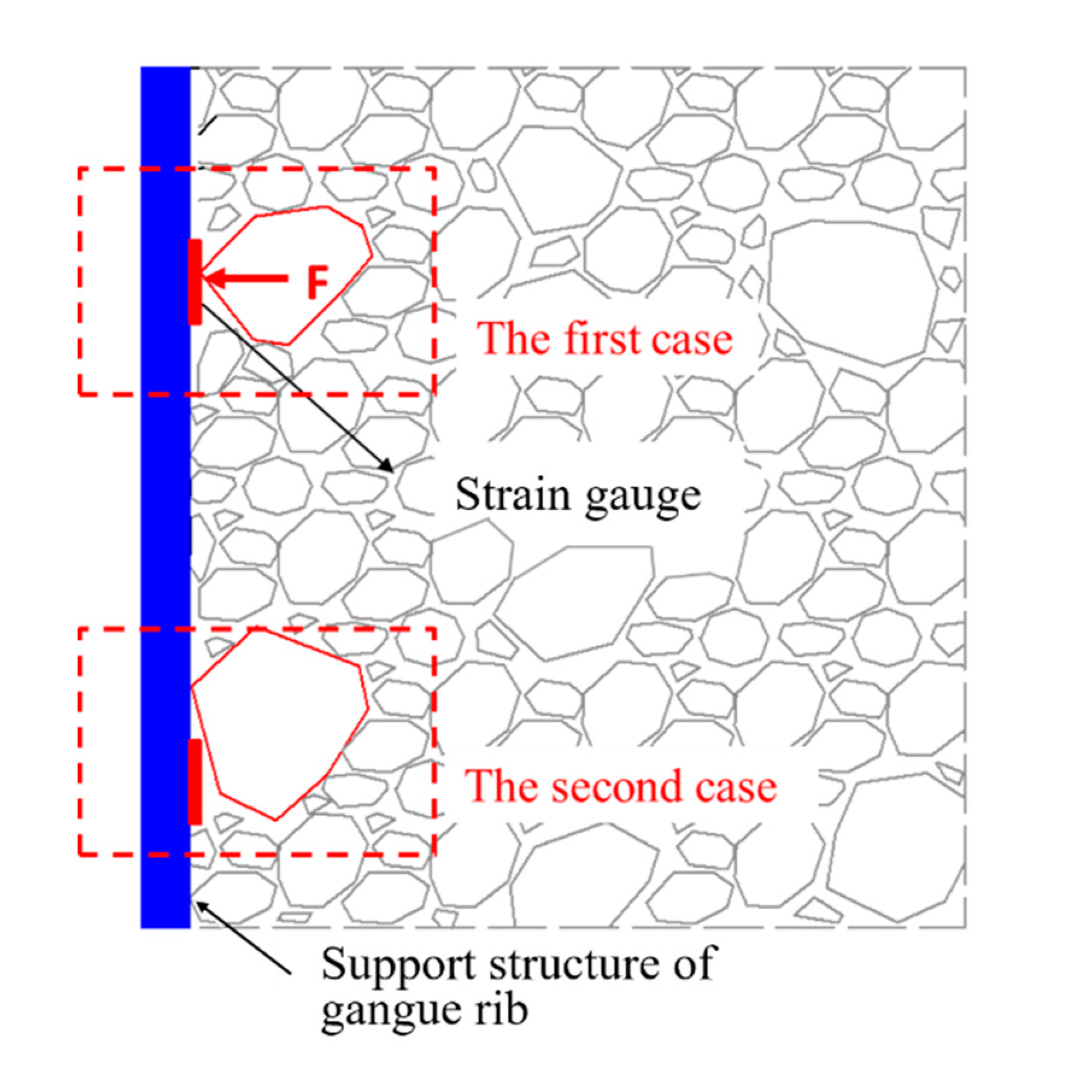
From above experimental results, a poor regularity of lateral stress generated by sample S-3 was observed. The phenomenon was illustrated in
Figure 15.
It can be seen that the contact between fine-sized crushed rocks and support structure is more sufficient than the larger-sized crushed rocks. Stress concentration (the first case of
Figure 15) and zero-contact (the second case of
Figure 15) are more likely to occur in larger-sized crushed rocks.
6. Conclusions
The conclusions drawn from this research are as follows:
(1) An innovative experimental device was developed to simulate the boundary conditions of the GERRF method. Using the device, the compressing tests were conducted to study the deformation behaviors of crushed rocks with different particle sizes in gob side of GERRF method.
(2) In tests, the accumulated axial deformation of the crushed rocks increased with increasing axial stress. As the particle size increased, the accumulated axial deformation decreased under the same axial stress. In addition, the skeletal loading-bearing effect was found in the samples with larger sized particles. And the entire deformation process of those samples can be divided into structural adjustment, skeleton load-bearing and crushing cum filling phases.
(3) The periodic deformation of the crushed mudstones includes instantaneous compressive deformation and creep deformation. Regardless of the particle size of the crushed rocks, the instantaneous compressive deformation decreased with the increase of loading stage. However, the different change laws of creep deformation were observed in the samples with different particle size. For the sample S-1, the creep deformations at each loading stage were roughly the same. But for samples S-2 and S-3, the creep deformation was minimum at the the skeletal load-bearing phase, but increased when it entered the crushing cum filling phase.
(4) There were two types of periodic stress-strain curves for crushed rocks. The “down-concave” stress-strain curve indicated that the deformation of crushed rocks was mainly caused by the compression of void spaces. While the “upper-convex” curve is the result of particles crushing and particles filling again.
(5) With the increase of particle size, the lateral stress generated on the support structure decreases under the same axial stress. Additionally, a poor regularity of lateral stress generated by crushed rocks with larger- sized particles was observed in tests. Under the condition that lateral pressure shows good regularity, a linear relationship between the axial stress and lateral stress generated by crushed rocks was established to be of the form: .
Author Contributions
All the authors contributed to this paper. Q.W. prepared and edited the manuscript. Z.G. provided theoretical and methodological guidance in the research process. S.Y., C.Z. and D.Y. partially participated in literature search and data processing. All authors have read and agreed to the published version of the manuscript.
Funding
This research was supported by the Science and Technology Project of Langfang City, China (grant number 2020013039), the Special Fund of Basic Research and Operating of North China Institute of Science & Technology (grant number 3142020001), and the State Scholarship Fund of China, the National Natural Science Foundation of China (grant number 51479195).
Institutional Review Board Statement
Not applicable.
Informed Consent Statement
Not applicable.
Data Availability Statement
Not applicable.
Acknowledgments
We are grateful to China University of Mining and Technology for providing us with the experimental platform and all the reviewers for their specific comments and suggestions.
Conflicts of Interest
The authors declare no conflict of interest.
References
- Zhang, N.; Yuan, L.; Han, C.L.; Xue, J.H.; Kan, J.G. Stability and deformation of surrounding rock in pillarless gob-side entry retaining. Saf. Sci. 2012, 50, 593–597. [Google Scholar] [CrossRef]
- Yang, H.Y.; Cao, S.G.; Wang, S.Q.; Fan, Y.C.; Wang, S.; Chen, X.Z. Adaptation assessment of gob-side entry retaining based on geological factors. Eng. Geol. 2016, 209, 143–151. [Google Scholar] [CrossRef]
- Guo, Z.B.; Wang, Q.; Li, Z.H.; He, M.C. Surrounding Rock Control of An Innovative Gob-side Entry Retaining with Energy-absorbing Supporting in Deep Mining. Low Carbon Technol. 2019, 14, 23–35. [Google Scholar] [CrossRef]
- Wang, Q.; Jiang, Z.H.; Jiang, B.; Gao, H.K.; Huang, Y.B.; Zhang, P. Research on an automatic roadway formation method in deep mining areas by roof cutting with high-strength bolt-grouting. Int. J. Rock Mech. Min. Sci. 2020, 128, 104264. [Google Scholar] [CrossRef]
- Yin, Q.; Wu, J.Y.; Zhu, C.; He, M.C.; Meng, Q.X. Shear mechanical responses of sandstone exposed to high temperature under constant normal stiffness boundary conditions. Geomech. Geophys. Geo Energy Geo-Resour. 2021, 7, 35. [Google Scholar] [CrossRef]
- He, M.C.; Zhu, G.L.; Guo, Z.B. Longwall mining “cutting cantilever beam theory” and 110 mining method in China-The third mining science innovation. J. Rock Mech. Geotech. Eng. 2015, 7, 483–492. [Google Scholar] [CrossRef] [Green Version]
- Wang, Q.; He, M.C.; Li, S.C.; Jiang, Z.H.; Wang, Y.; Qin, Q.; Jiang, B. Comparative study of model tests on automatically formed roadway and gob-side entry driving in deep coal mines. Int. J. Min. Sci. Technol. 2021. [Google Scholar] [CrossRef]
- He, M.C.; Gao, Y.B.; Yang, J.; Gong, W.L. An Innovative Approach for Gob-Side Entry Retaining in Thick Coal Seam Longwall Mining. Energies 2017, 10, 1785. [Google Scholar] [CrossRef] [Green Version]
- Yang, X.J.; Wang, E.Y.; Ma, X.G.; Zhang, G.F.; Huang, R.F.; Lou, H.P. A Case Study on Optimization and Control Techniques for Entry Stability in Non-Pillar Longwall Mining. Energies 2019, 12, 391. [Google Scholar] [CrossRef] [Green Version]
- He, M.C.; Gong, W.L.; Wang, J.; Qi, P.; Tao, Z.G.; Du, S.; Peng, Y.Y. Development of a novel energy–absorbing bolt with extraordinarily large elongation and constant resistance. Int. J. Rock Mech. Min. Sci. 2014, 67, 29–42. [Google Scholar] [CrossRef]
- Zhu, C.; He, M.C.; Karakus, M.; Zhang, X.H.; Tao, Z.G. Numerical simulations of the failure process of anaclinal slope physical model and control mechanism of negative Poisson’s ratio cable. Bull. Eng. Geol. Environ. 2021, 80, 3365–3380. [Google Scholar] [CrossRef]
- Tao, Z.G.; Zhu, C.; He, M.C.; Karakus, M. A physical modeling-based study on the control mechanisms of Negative Poisson’s ratio anchor cable on the stratified toppling deformation of anti-inclined slopes. Int. J. Rock Mech. Min. Sci. 2021, 138, 104632. [Google Scholar] [CrossRef]
- Zhou, N.; Han, X.L.; Zhang, J.X.; Li, M. Compressive deformation and energy dissipation of crushed coal gangue. Powder Technol. 2016, 297, 220–228. [Google Scholar] [CrossRef]
- Ma, D.; Bai, H.B.; Miao, X.X.; Pu, H.; Jiang, B.Y.; Chen, Z.Q. Compaction and seepage properties of crushed limestone particle mixture: An experimental investigation for Ordovician karst collapse pillar groundwater inrush. Environ. Earth Sci. 2016, 75, 1–12. [Google Scholar] [CrossRef]
- Kong, H.L.; Chen, Z.Q.; Wang, L.Z.; Shen, H.D. Experimental study on permeability of crushed gangues during compaction. Int. J. Miner. Process. 2013, 124, 95–101. [Google Scholar] [CrossRef]
- Ma, Z.G.; Gu, R.X.; Huang, Z.M.; Peng, G. Experimental study on creep behavior of saturated disaggregated sandstone. Int. J. Rock Mech. Min. Sci. 2014, 66, 76–83. [Google Scholar] [CrossRef]
- Su, C.L.; Li, G.C.; Gomah, M.E.; Xu, J.H.; Sum, Y.T. Creep characteristics of coal and rock investigated by nanoindentation. Int. J. Rock Mech. Min. Sci. 2020, 30, 769–776. [Google Scholar]
- Guo, Z.B.; Wang, Q.; Yin, S.Y. The creep compaction behavior of crushed mudstones under the step loading in underground mining. Int. J. Coal Sci. Technol. 2019, 6, 408–418. [Google Scholar] [CrossRef] [Green Version]
- Yu, B.Y.; Chen, Z.Q.; Wu, J.Y. Experimental study on compaction and fractal characteristics of saturated broken rocks with different initial gradations. J. Min. Saf. Eng. 2016, 33, 342–347. [Google Scholar]
- Ma, Z.G.; Guo, G.L.; Chen, R.H.; Mao, X.B. An experimental study on the compaction of water-saturated over-broken rock. Chin. J. Rock Mech. Eng. 2004, 25, 1139–1144. [Google Scholar]
- Zhang, J.X.; Li, M.; Liu, Z. Fractal characteristics of crushed particles of coal gangue under compaction. Powder Technol. 2017, 305, 12–18. [Google Scholar] [CrossRef]
- Zhang, J.W.; Wang, H.L.; Chen, S.J.; Li, Y.L. Bearing deformation characteristics of large-size broken rock. J. China Coal Soc. 2018, 43, 1000–1007. [Google Scholar]
Figure 1.
Principle of the GERRF method: (a) No roof pre-fracturing; (b) With roof pre-fracturing.
Figure 1.
Principle of the GERRF method: (a) No roof pre-fracturing; (b) With roof pre-fracturing.
Figure 2.
Design principle of the innovative experimental device: (a) Schematic diagram of the structure of the GERRF method; (b) The structural composition of the experimental device.
Figure 2.
Design principle of the innovative experimental device: (a) Schematic diagram of the structure of the GERRF method; (b) The structural composition of the experimental device.
Figure 3.
The MTS hydraulic servo loading system.
Figure 3.
The MTS hydraulic servo loading system.
Figure 4.
Crushed mudstone samples for the tests.
Figure 4.
Crushed mudstone samples for the tests.
Figure 5.
The specific locations and numbering of the strain gauges in tests.
Figure 5.
The specific locations and numbering of the strain gauges in tests.
Figure 6.
Loading path in the tests.
Figure 6.
Loading path in the tests.
Figure 7.
The stress-strain curves of the tested crushed mudstone samples for the entire loading process under the incremental loading.
Figure 7.
The stress-strain curves of the tested crushed mudstone samples for the entire loading process under the incremental loading.
Figure 8.
The change rule of axial strain increment corresponding to each loading stage for S-1, S-2 and S-3.
Figure 8.
The change rule of axial strain increment corresponding to each loading stage for S-1, S-2 and S-3.
Figure 9.
The entire deformation process of the crushed rock sample with skeleton load-bearing effect.
Figure 9.
The entire deformation process of the crushed rock sample with skeleton load-bearing effect.
Figure 10.
The periodic stress-strain curves of sample S-1 at each loading stage.
Figure 10.
The periodic stress-strain curves of sample S-1 at each loading stage.
Figure 11.
The periodic stress-strain curves of sample S-2 at each loading stage.
Figure 11.
The periodic stress-strain curves of sample S-2 at each loading stage.
Figure 12.
The periodic stress-strain curves of sample S-3 at each loading stage.
Figure 12.
The periodic stress-strain curves of sample S-3 at each loading stage.
Figure 13.
The lateral stress of the D column monitoring points.
Figure 13.
The lateral stress of the D column monitoring points.
Figure 14.
The deformation mechanism of two types of stress-strain curves: (a) down-concave type; (b) upper-convex type.
Figure 14.
The deformation mechanism of two types of stress-strain curves: (a) down-concave type; (b) upper-convex type.
Figure 15.
The schematic diagram for a poor regularity of lateral stress generated by larger-sized crushed rocks.
Figure 15.
The schematic diagram for a poor regularity of lateral stress generated by larger-sized crushed rocks.
Table 1.
The periodic axial strain of crushed mudstone sample at each loading stage.
Table 1.
The periodic axial strain of crushed mudstone sample at each loading stage.
| Particle Size | The Periodic Axial Strain ε (%) |
|---|
| 1st Stage | 2nd Stage | 3rd Stage | 4th Stage | 5th Stage | 6th Stage | 7th Stage | 8th Stage | 9th Stage |
|---|
| S-1 (10–30) | 6.59 | 3.37 | 2.55 | 1.99 | 1.71 | 1.19 | 1.28 | / | / |
| S-2 (30–60) | 4.36 | 2.64 | 1.91 | 1.73 | 1.65 | 1.64 | 1.19 | 2.04 | / |
| S-3 (60–80) | 3.30 | 1.97 | 1.61 | 1.12 | 1.11 | 0.99 | 2.11 | 2.14 | 2.69 |
Table 2.
The periodic axial instantaneous strain of crushed mudstone samples at each loading stage.
Table 2.
The periodic axial instantaneous strain of crushed mudstone samples at each loading stage.
| Particle Size | The Periodic Axial Instantaneous Strain ε1 (%) |
|---|
| 1st Stage | 2nd Stage | 3rd Stage | 4th Stage | 5th Stage | 6th Stage | 7th Stage | 8th Stage | 9th Stage |
|---|
| S-1 (10–30) | 5.80 | 2.63 | 1.75 | 1.20 | 0.88 | 0.6 | 0.56 | / | / |
| S-2 (30–60) | 3.80 | 2.22 | 1.33 | 1.05 | 0.81 | 0.7 | 0.58 | 0.45 | / |
| S-3 (60–80) | 3.00 | 1.70 | 1.34 | 0.90 | 1.10 | 0.55 | 0.63 | 0.40 | 0.25 |
Table 3.
The periodic creep strain of crushed mudstone samples at each loading stage.
Table 3.
The periodic creep strain of crushed mudstone samples at each loading stage.
| Particle Size | The Periodic Creep Strain ε2 (%) |
|---|
| 1st Stage | 2nd Stage | 3rd Stage | 4th Stage | 5th Stage | 6th Stage | 7th Stage | 8th Stage | 9th Stage |
|---|
| S-1 (10–30) | 0.79 | 0.74 | 0.80 | 0.79 | 0.83 | 0.59 | 0.72 | / | / |
| S-2 (30–60) | 0.56 | 0.42 | 0.58 | 0.68 | 0.84 | 0.94 | 0.61 | 1.59 | / |
| S-3 (60–80) | 0.30 | 0.27 | 0.27 | 0.22 | 0.01 | 0.44 | 1.48 | 1.74 | 2.44 |
Table 4.
Regression coefficients of the linear relationship between axial stress and lateral stress generated by crushed mudstones.
Table 4.
Regression coefficients of the linear relationship between axial stress and lateral stress generated by crushed mudstones.
| Particle Size | Monitor Point | Regression Coefficient | Correlation Coefficients |
|---|
| a | b |
|---|
| S-1 (10–30) | D-1 | 1.41 | 106.25 | 0.977 |
| D-2 | 2.00 | 160.00 | 0.978 |
| D-3 | 0.94 | 99.16 | 0.963 |
| D-4 | 0.64 | 77.92 | 0.954 |
| S-2 (30–60) | D-1 | 0.53 | −4.58 | 0.993 |
| D-2 | 0.77 | 0 | 0.998 |
| D-3 | 0.34 | −22.92 | 0.978 |
| D-4 | 0.13 | 2.92 | 0.989 |
| S-3 (60–80) | D-1 | 0.88 | 64.17 | 0.884 |
| D-2 | 1.58 | 186.67 | 0.910 |
| D-3 | 2.35 | 18.33 | 0.997 |
| D-4 | 1.69 | 45 | 0.994 |
| Publisher’s Note: MDPI stays neutral with regard to jurisdictional claims in published maps and institutional affiliations. |
© 2021 by the authors. Licensee MDPI, Basel, Switzerland. This article is an open access article distributed under the terms and conditions of the Creative Commons Attribution (CC BY) license (https://creativecommons.org/licenses/by/4.0/).


