Abstract
As environmental regulations have been strengthened worldwide since the Paris Climate Agreement, the automobile industry is shifting its production paradigm to focus on eco-friendly vehicles such as electric vehicles and hydrogen-battery vehicles. Governments are banning fossil fuel vehicles by law and expanding the introduction of green vehicles. The energy efficiency of electric vehicles that use a limited power source called batteries depends on the driving environment. Applying a two-speed transmission to an electric vehicle can optimize average speed and performance efficiency at low speeds, and achieve maximum speed with minimal torque at high speeds. In this study, a two-speed transmission for an electric vehicle has been developed, to be used in a compact electric vehicle. This utilizes a planetary gear of a total of three pairs, made of a single module which was intended to enable two-speed. The ring gear was removed, and the carrier was used in common. When shifting, the energy used for the speed change is small, due to the use of the simple method of fixing the sun gear of each stage. Each gear was designed by calculating bending strength and surface durability, using JGMA standards, to secure stability. The safety factor of the gears used in the transmission is as follows: all gears have been verified for safety with a bending strength of 1.2 or higher and a surface pressure strength of 1.1 or higher. The design validity of the transmission was verified by calculating the gear meshing ratio and the reference efficiency of the gear. The transmission to be developed through the research results of this paper has a simple and compact structure optimized for electric vehicles, and has reduced shift shock. In addition, energy can be used more efficiently, which will help improve fuel economy and increase drive range.
1. Introduction
The spread of electric vehicles using environmentally friendly fuels is increasing. The rapid development of battery technology and automobile technology has become a starting point. In addition, the success of the electric vehicle market has been accelerated, as major car manufacturers have reorganized their production around electric vehicles since the “diesel gate” in 2015, when the emission control scandal broke out [1,2,3,4]. According to the International Energy Agency, the number of electric vehicles sold in 2017 was around 1.1 million units, an increase of 54% from the previous year, and as of 2017, the number of global electric vehicles was close to 3.1 million. In particular, 580,000 electric vehicles were sold in China in 2018, up 72% from a year earlier. China has led the global electric vehicle market, accounting for around half of the world’s sales. The United States also saw a 75% increase year-on-year to 280,000 units [5]. Several recent studies [6,7,8] have investigated the application of multi-speed transmissions to electric vehicle platforms [9]. These are viewed as one of the most promising options that meet the needs for both a wider range of torque applications and higher energy efficiencies than single speed equivalents [10,11].
A transmission can be used, depending on driving conditions, with greater torque and higher speed than a vehicle without a transmission [12]. This reduces unnecessary losses and by doing so increases drive range. In the case of an electric vehicle, powered by batteries which have a limited capacity, power transmission efficiency is the most important consideration. If an electric vehicle is heavy, there is a loss of power transmission due to the weight of the vehicle. These results show that heavy electric vehicles that are less efficient have a reduced drive range, and have batteries that need to be charged more frequently. If the weight of the vehicle is reduced by 10%, the fuel efficiency of the vehicle is improved by about 3% to 8%, the acceleration performance is improved by 8%, and the emission of environmental pollutants is also reduced [13,14,15,16,17,18]. There is a need for a transmission that is adaptable to various driving environments, and that optimizes torque and speed according to the driving speed [19].
2. The Necessity and the Purpose of the Study
2.1. The Necessity of the Study
2.1.1. Necessity of Study on Electric Vehicle Two-Speed Transmission
The spread of cars using environmentally friendly alternative energy is increasing rapidly, with the growth of electric vehicles being the most noticeable. Electric vehicles are eco-friendly vehicles that use electric motors and batteries. In general, most electric vehicles currently do not use transmissions. Due to the power characteristics of the electric motor, which is the power source of the batteries, a single gear ratio reducer is used instead of a transmission.
Figure 1A shows the power characteristics of the internal combustion engine. The maximum torque is generated in proportion to the rotational speed by generating a relatively constant maximum torque up to a certain speed. In general, a car needs a large torque to accelerate from a standstill and reach a certain speed. To maintain high speeds, only the torque needed to maintain the speed is required, and this can be achieved with a relatively small torque. The issue here is that internal combustion engines have some difficulty in reconciling these two requirements in terms of power characteristics.
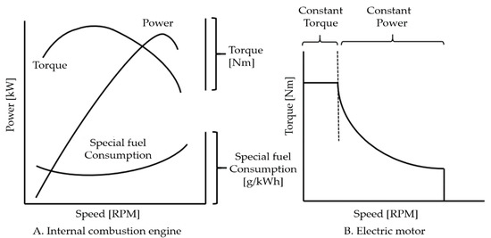
Figure 1.
Power characteristics of internal combustion engine and electric motors.
Figure 1B shows the power characteristic of the electric motor. The electric motor has a characteristic of generating a maximum torque at a low rotational speed, and generating a low torque at a high rotational speed, thereby generating a constant maximum output regardless of the rotational speed.
The characteristics of the electric motor show a constant power output with high torque at low speed and low torque at high speed [20].
Nevertheless, the reasons for using transmissions in electric vehicles are as follows.
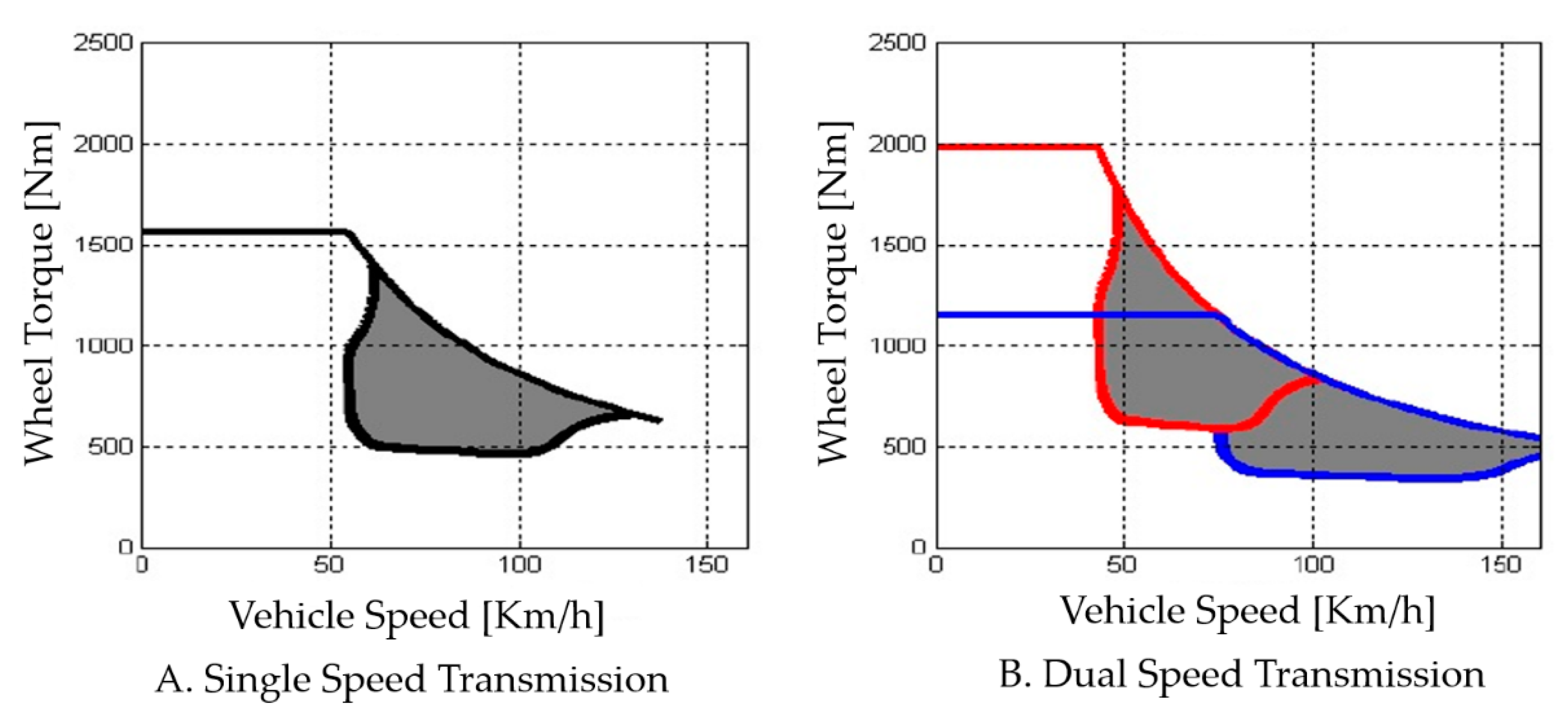
Figure 2 is an energy efficiency graph of an electric vehicle with a single reducer and a two-speed transmission. The gray shaded area is where the electric motor operates at high efficiency. A wider high-efficiency range can be seen when using a two-speed transmission than when using a single reducer. Due to this, it can improve adaptability and responsiveness to various driving environments. Many countries around the world, including Korea, have large and small hills and various types of roads that are hard on vehicles. To overcome this, a transmission is needed. When torque optimization is possible according to the driving speed, it can adapt more quickly to various driving environments and respond faster. Electric vehicles using a single gear reducer have no option but to increase the motor size if they are to achieve the maximum torque required [21].
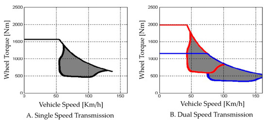
Figure 2.
Increase in efficiency range of two speed electric vehicle.
However, when one adapts to this driving environment without a transmission, the size of the motor increases to obtain greater torque, which increases the vehicle body weight and so battery consumption rate, which impairs practicality. In one case study, which considered various driving environments, virtual driving was performed in the FTP75 driving mode of a vehicle. A comparison of a single reduction gear with a maximum torque of 890 Nm and a three-speed transmission with a maximum torque of 450 Nm showed that a vehicle with a transmission showed an energy saving of 29% [22].
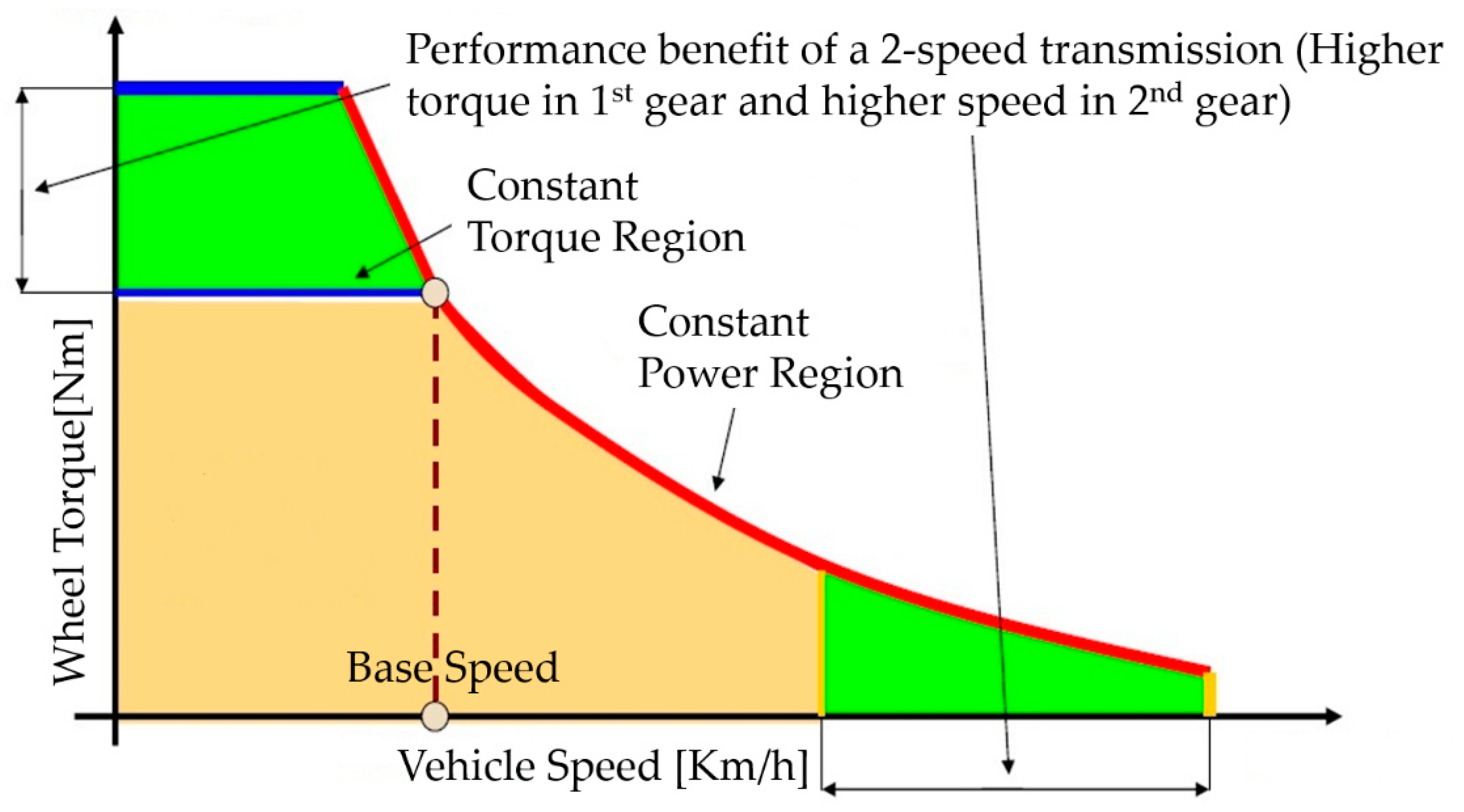
Second, with a transmission it is possible to improve both fuel economy and increase mileage. Figure 3 shows high characteristics in the operating range of the specified range. The range shown in red in Figure 3 shows high energy efficiency. Equipped with a transmission, it is possible to drive with high efficiency in various driving environments. It uses energy from a limited energy source, the battery, more efficiently, resulting in improved fuel economy and increased mileage.
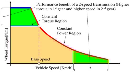
Figure 3.
Torque and speed changes of two speed electric vehicles.
2.1.2. Problems with Conventional Transmissions
To change the gear ratio in the existing transmission structure, it is necessary to connect gears with driven shafts rotating at different speeds. To this end, constant-mesh types use a dog clutch that connects power between gears. When connecting between dog clutches, the clutch suffers from wear and tear due to heavy friction that is generated due to the differing rotational speeds, so the quality of the shift is not good, and the dog clutch sees wear problems occur. In order to solve this problem, a friction clutch called a synchronizer ring is used to reduce the speed differences before the dog clutch is connected.
A synchro mesh type is used to match the number of rotations before the dog clutch is engaged. As mentioned in the previous paragraph, this still does not solve the fundamental problem of the structure, which requires a connection between gears with different rotational speeds [23].
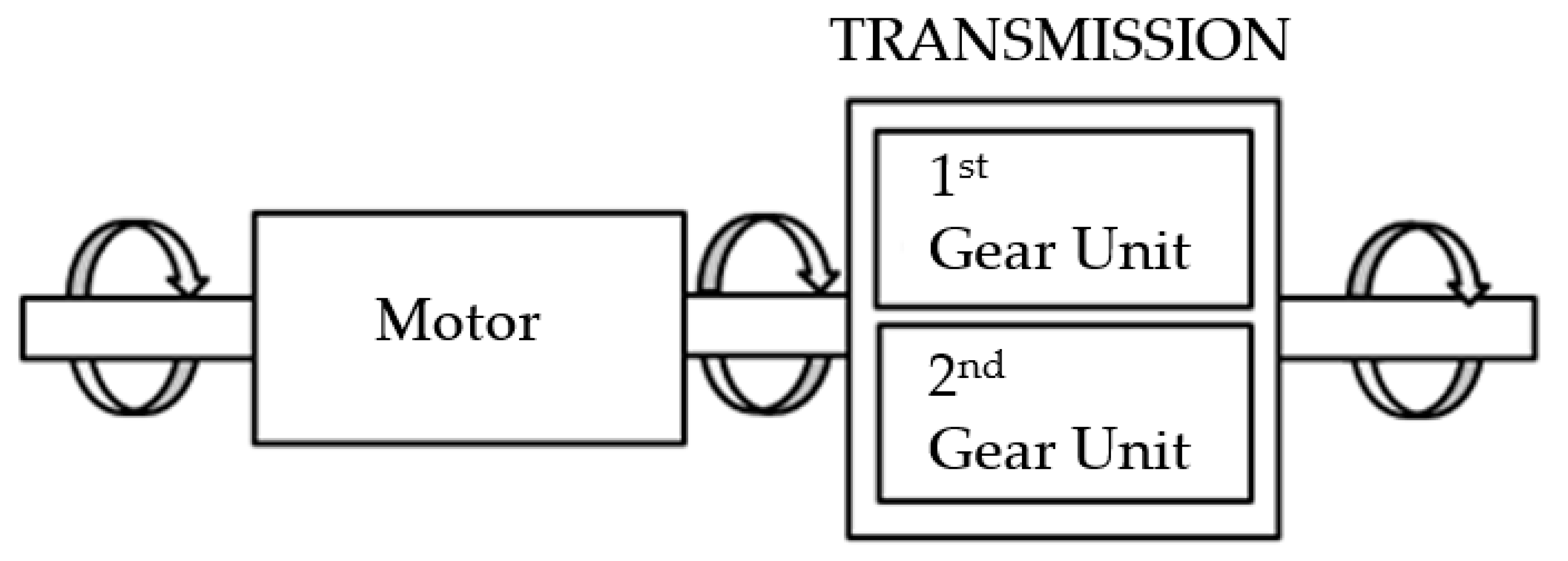
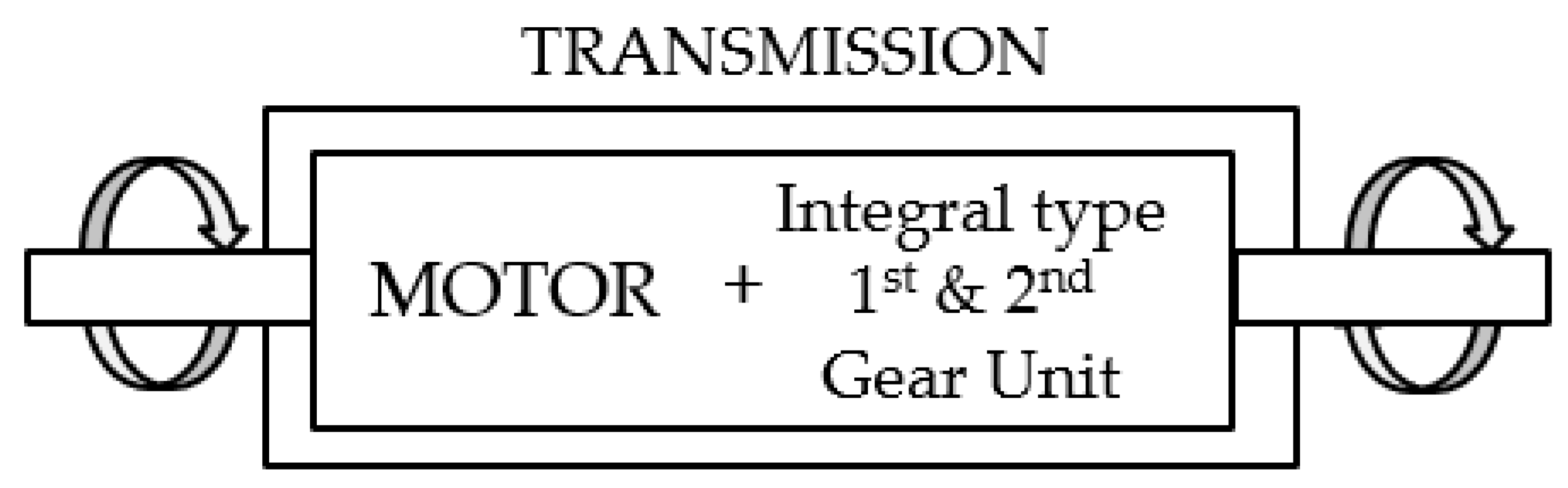
Figure 4 shows the layout of a two-speed transmission for electric vehicles made using planetary gears. As shown in the figure, the first speed and second speed planetary gear modules are configured separately. This configuration increases the transmission housing size and increases the number of parts used. In other words, the weight increases by the increased volume, reducing fuel efficiency and drive range, and increasing manufacturing costs.

Figure 4.
Layout of the existing two-speed transmission for EV.
In the case of the transmission designed in this study, a planetary gear structure is used, and the sun gear is selectively fixed. To change the gear ratio, one must first release the clutch of the existing stage that is currently connected to put the sun gear of the planetary gear module in a no-load state. Then, synchronizing the number of rotations of the motor to the desired speed of transmission, the rotational speed of the planetary gear module’s sun gear at the target stage reaches zero. Finally, the shift is completed when the simple operation of fixing the sun gear in which the clutch of the target stage is stopped is performed [24,25,26,27,28,29].
In conventional transmissions, gear-to-gear connections with different rotational speeds result in shifting wear and tear of the shifting elements. In the process of synchronizing the speed between the gears, the rotational speed of the gear and the energy consumption of the dog clutch transfer occurs. The transmission designed in this study uses a structure that simply fixes the sun gear of the planetary gear module that is stopped by synchronizing the motor speed. With this configuration, the shifting shocks and abrasion of shifting elements do not occur, and only the energy for the sun gear control is required. In other words, the transmission energy efficiency is higher than that of existing transmissions, making this a structure suitable for an electric vehicle where efficiency management is very important due to the use of a limited power source, such as a battery [30].
2.2. The Purpose of the Study
Most roads have signal and traffic flows, and this causes the vehicle to stop and start repeatedly. Besides, most cities have many roads that require large torque in addition to the plain. Transmission is required to meet these conditions and to ensure driving comfort and driving stability. In this study, we developed a two-speed transmission for a 100 kW small electric vehicle. Each gear was calculated according to JGMA standard, and the transmission was designed using a 3D modeling tool.
3. Transmission Structure Design and Tooth Profile Design
3.1. Design of Transmission Planetary Gear Module
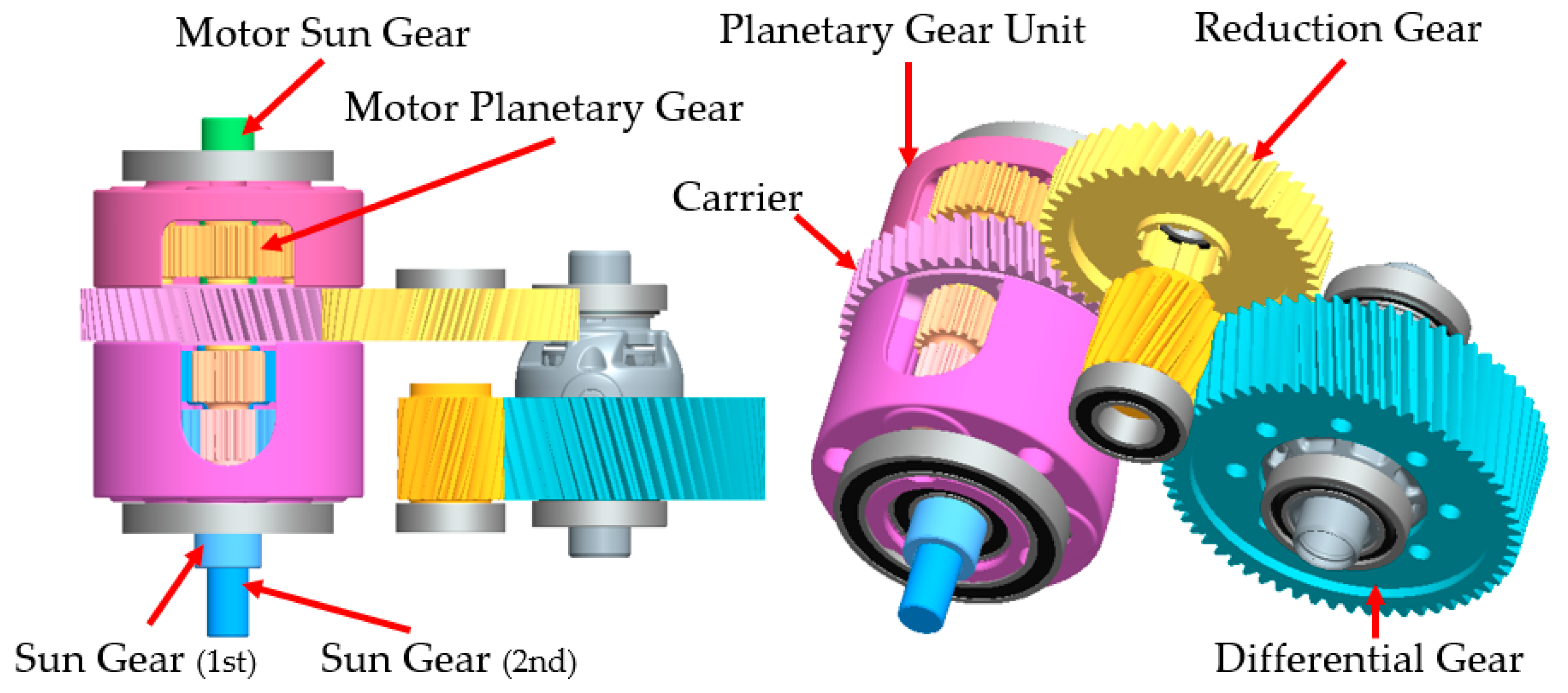
A pair of planetary gear sets were then added, to insert the motor into the planetary gear unit. The feature of this structure is that no ring gear is required. Power is transmitted directly to the planetary gear module via the motor sun gear. It consists of a total of three pairs of planetary gear sets, a carrier, and reduction gear. The ring gear was removed, and three planetary gears were coaxial. Power input from the motor sun gear is transmitted through the motor planetary gear, by selectively fixing the first and second sun gears; the output reduced by the gear ratio of each stage is transmitted to the differential gear through the carrier.
Figure 5 shows the two-speed transmission layout.

Figure 5.
New design 2-speed transmission layout.
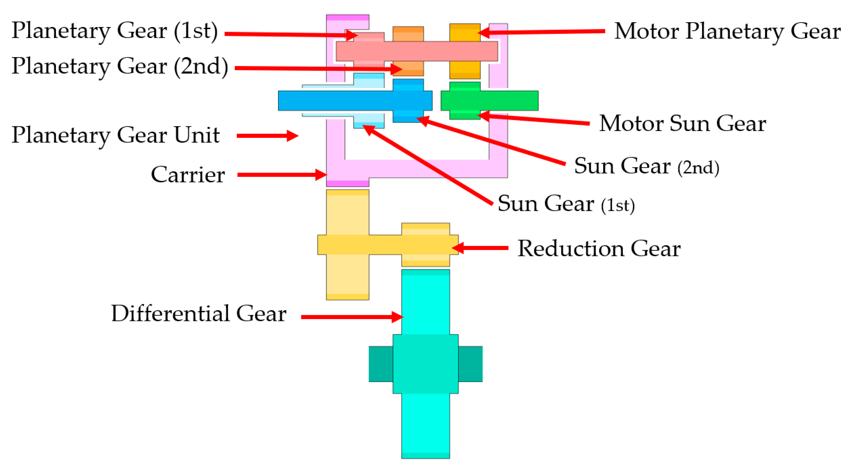
Figure 6 shows the transmission gear structure: a structure in which a reduction gear has been added between the planetary gear unit and the differential gear. The advantage of this structure is that the size of the differential gear and the carrier gear can be greatly reduced, and various gear ratios realized.
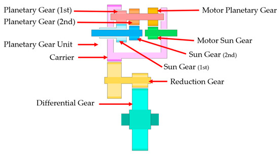
Figure 6.
Two-speed transmission structure drawings.
3.2. Design of 2-Speed Transmission
3.2.1. 3D Modeling 2-Speed Transmission
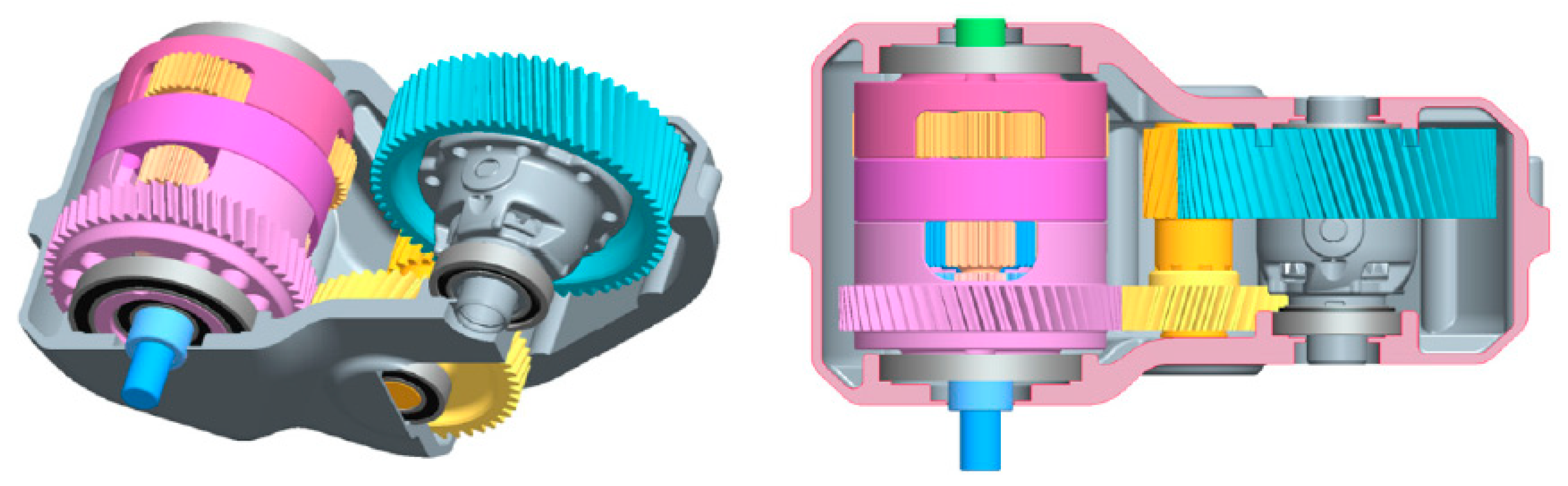
The two-speed transmission was 3D modeled using design tools. Figure 7 is a 3D model of a two-speed transmission. It is composed of a planetary gear module, a reduction gear and a differential gear. Figure 8 is an exploded view of the planetary gear module. This consists of a first speed planetary gear set, a second speed planetary gear set, a motor planetary gear set, and a carrier.

Figure 7.
Two-speed transmission 3D modeling.
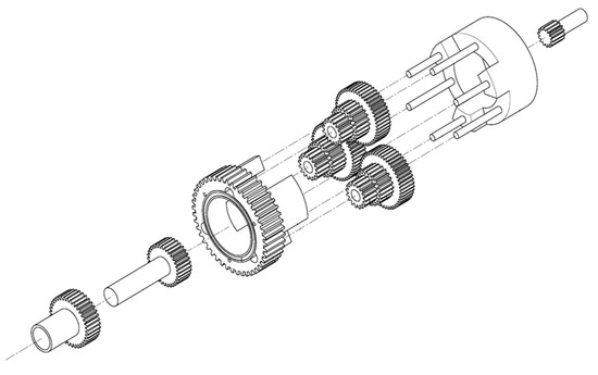
Figure 8.
Two-speed transmission planetary gear module exploded view.
3.2.2. Shift Mechanism of New Type Transmission
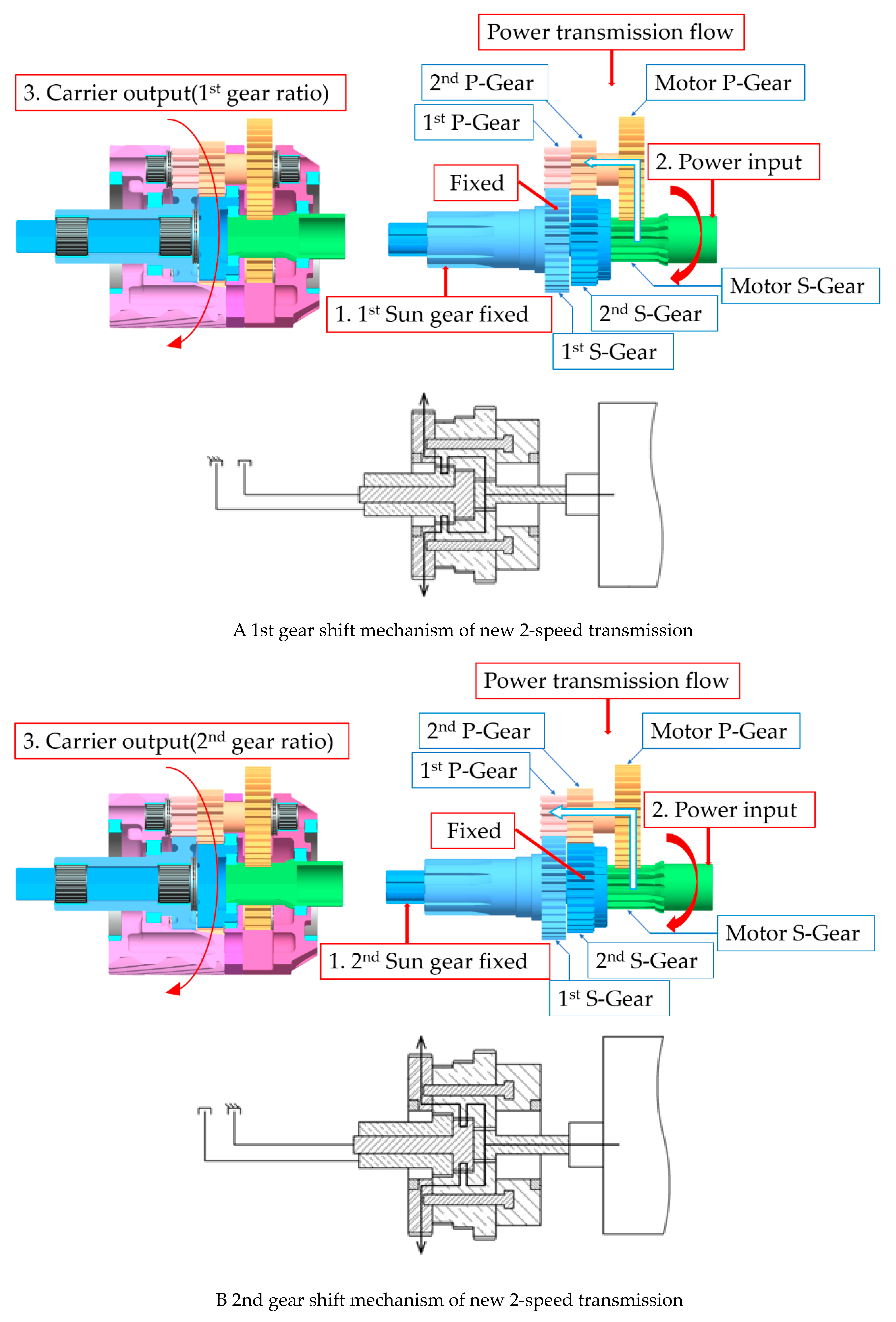
Figure 9A,B have been included to make the transmission mechanism of the transmission easy to understand.
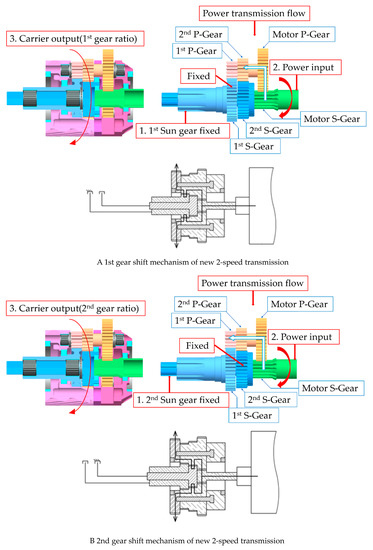
Figure 9.
The Shifting mechanism of new two-speed transmission for each speed.
First, in Figure 9A, the first gear shift mechanism locks the first gear in the starting and first gear shifts. Then, the motor’s power enters the planetary gear module through the motor sun gear and is transmitted to the motor planetary gear. The transmitted power is transmitted to the planetary gear of each speed coaxial with the motor planetary gear. Power reduced by the first gear ratio is transmitted to the carrier. The power transmitted from the carrier gear to the reduction gear is reduced to the final reduction ratio, and then transmitted to the differential gear.
Second, in Figure 9B, the second gear shift mechanism locks the second gear in the starting and second gear shifts. Then, the motor’s power enters the planetary gear module through the motor sun gear and is transmitted to the motor planetary gear. The transmitted power is transmitted to the planetary gear of each speed coaxial with the motor planetary gear. Power reduced by the second gear ratio, is transmitted to the carrier. The power transmitted from the carrier gear to the reduction gear is reduced to the final reduction ratio and then transmitted to the differential gear.
The two-speed transmission in this paper transfers power through the motor sun gear. It is delivered through the carrier at the gear ratio shifted through the first planetary gear set or the second planetary gear set. It has a two-speed transmission system structure that shifts by selectively fixing each sun gear. When the prime mover reaches a certain speed that must be reached after shifting, since the speed of the sun gear that needs to be fixed is zero, the energy required for shifting is small and so highly efficient shifting is possible. Theoretically, the shift shock can be reduced to zero, and the sun gear control mechanism can be simplified. Finally, this mechanism is suitable for battery-powered electric vehicles and can also improve energy efficiency.
3.2.3. Calculate Planetary Gear Reduction Ratio
When the sun gear is fixed, the gear ratio of each stage can be calculated from the number of rotations of the carrier. Table 1 sets out calculations for the speed components of the gears inside the transmission in the first and second stages. The reduction ratios of the planetary gear module are the same as in Formulas (1) and (2). Formula (1) represents the first gear ratio, and Formula (2) represents the second gear ratio. All conditions were calculated based on sun gear fixing and carrier output.

Table 1.
Calculation of first and second planetary gear set gear ratio.
The gear ratio of the first gear is 3.4511: 1 and the gear ratio of the second gear is 1.8366: 1. The final reduction ratio passed through the reduction gear to the differential gear is 10.7198: 1 in the first stage and 5.7047: 1 in the second stage. The ratio between the first and second stages is 1.8791. This is the figure that met the originally planned target.
Motor Sun Gear (SM), Motor Planetary Gear (PM), 1st Speed Sun Gear (S1), 1st Speed Planetary Gear (P1), 2nd Speed Sun Gear (S2), 2nd Speed Planetary Gear (P2), Number of gear teeth (Z).
3.3. Evaluation of Gears Strength
3.3.1. Calculation of Bending Strength and Surface Durability
Table 2 summarizes the formulas for the bending stress and the surface durability. The safety factor against the root bending stress is preferably at least 1.2 or more [31,32,33,34,35,36]. It is preferable that the safety factor against the surface durability has a value of at least 1.1 or more [37,38,39,40].
Table 2.
Formulas of bending strength and surface durability.
Gear specifications were selected based on the reference data and the above formula.
3.3.2. Final Gear Specification
The transmission to be designed in this paper is designed to produce the optimum specification that meets the driving conditions by calculating the strength of the gear. The contents are summarized in Table 3, Table 4, Table 5, Table 6, Table 7 and Table 8 below.
Table 3.
Specification of planetary gear module internal gear.
Table 4.
Specification of planetary gear module internal gear bending strength.
Table 5.
Specification of planetary gear module internal gear surface durability.
Table 6.
Specification of planetary gear module external gear.
Table 7.
Specification of planetary gear module external gear bending strength.
Table 8.
Specification of planetary gear module external gear surface durability.
As illustrated in the above table, both a surface durability and bending strength were obtained. The safety factor of the planetary gear module, internal gear and external gear are all above 1.2.
3.4. Meshing Efficiency Analysis of Transmission
The reason for calculating the reference efficiency of the gear is that the calculated value shows how the efficiency of the system varies. Therefore, after the gear specification is confirmed, the calculated efficiency of the reference efficiency can be used to determine the approximate efficiency of the transmission drive mechanism.
Since the efficiency of the planetary gear mechanism is calculated based on the meshing efficiency of the gear (this is the reference efficiency) when fixing the carrier, it is possible to increase the efficiency of the planetary gear mechanism by using a gear that has a high reference efficiency. In the gear device, power loss includes friction loss on the tooth surface, bearing loss, agitation loss of lubricating oil, and the like. When calculating the reference efficiency of the gear, it is assumed that the bearing loss is smaller than the gear surface loss, and that most of the loss is due to gear surface friction loss.
The gear meshing ratio is an important factor affecting gear performance, vibration, strength, and rotation. In general, gears with a large meshing ratio have low noise and vibration, flexible rotation, and high strength. In addition, the reference efficiency of the gear can be obtained by using the gear meshing ratio. It is possible to see how the efficiency of the system varies through the gear reference efficiency, and it is possible to increase the efficiency of the planetary gear mechanism by using a gear with a high reference efficiency.
To calculate the gear reference efficiency, calculation of the gear meshing ratio is preceded. Table 9 summarizes formulas for obtaining the gear meshing ratio and formulas for gear reference efficiency. Spur gears were used for all sun and planet gears in the transmission. Helical gears were used as carrier gear, reducer input gear, output gear, and differential gear. The spur gear was calculated using the formula 15 in Table 9, and the gear meshing ratio of the helical gear was calculated using formula 18. is the approach meshing ratio and is the retreat meshing ratio. The sum of and is the total meshing ratio. Table 10 summarizes the formulas used to determine the approach meshing ratio, the retreat meshing ratio, and the tooth pressure angle. Table 11 summarizes the gear meshing ratio and gear reference efficiency using Table 9 and Table 10 [41].
Table 9.
Formulas of gear meshing ratio and gear refence efficiency.
Table 10.
Base formulas of gear refence efficiency.
Table 11.
Gear refence efficiency.
If the meshing efficiencies of gears A and B are and the meshing efficiencies of gears C and D are , the efficiency can be obtained from the following equation.
The gear efficiency in the planetary gear module obtained by the above formula is 97.993% at the first gear shift, and 98.119% at the second gear shift. This is the median between the mixed lubrication coefficient and the boundary lubrication coefficient among the friction coefficients. It is important to note that during actual lubricated operation a higher efficiency is expected. The overall reference efficiency of the entire gear of the planetary gearbox is shown in Table 12 below. As a result of the analysis of the reference efficiency, it was calculated that the first and second stages have a meshing efficiency of more than 96%.
Table 12.
Two-speed transmission gear train efficiency.
This is close to the maximum efficiency of a general manual transmission at 96% and the maximum efficiency of a dual clutch transmission at 95% [42,43,44,45].
3.5. Two-Speed Transmission Housing Design
Figure 10 shows the two-speed transmission housing design. It consists of the planetary gear unit, reduction gear and differential gear.

Figure 10.
Electric vehicle two-speed transmission housing.
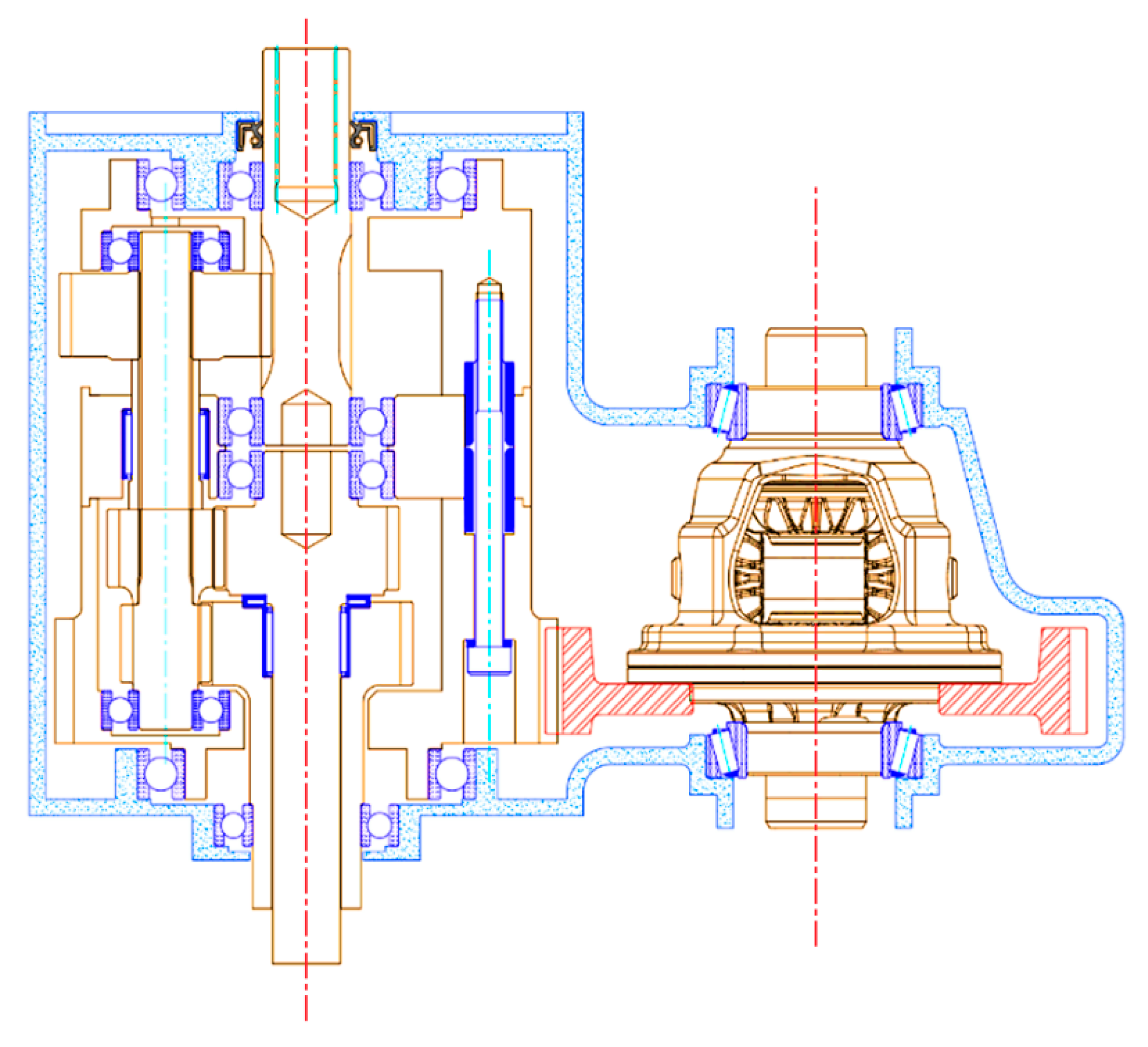
Figure 11 shows the two-speed transmission 2D drawing.
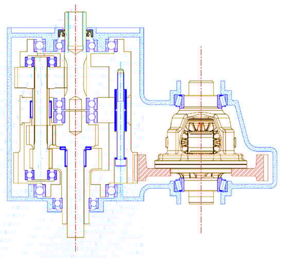
Figure 11.
Electric vehicle two-speed transmission 2D drawing.
4. Conclusions
In this study, a new two-speed transmission which uses multiple planetary gear sets was designed for electric vehicles. In order to achieve a compact design, each gear is coaxially placed to reduce space to a minimum. The two-speed transmission design was carried out with the minimum space to also ensure safety. In the design process, the ring gear was removed, and the carrier gear was shared, since this would be the weight of the transmission to be reduced and would further reduce the size of the transmission housing. The bending strength and surface durability of each gear was calculated, adhering to the JGMA standard, to ensure safety. Also, by calculating the reference efficiency of the transmission, the validity of the two-speed transmission design was confirmed.
Finally, through research, the results obtained in this paper are as follows.
- (1)
- An electric vehicle two-speed transmission mechanism was envisioned, and 3D modeling was undertaken. The number of parts is reduced by means of a mechanism different from a conventional transmission with each planetary gear and sun gear coaxially configured to eliminate unnecessary space. The design was made even more compact by eliminating the ring gear.
- (2)
- The characteristics of the two-speed transmission mechanism, detailed in this paper, allows for the speed and acceleration of the sun gear to be fixed to “0”. Thus, it is judged to be an advantageous structure for automobiles powered by batteries because of the low shift shock and the low energy required for shifting.
- (3)
- Gear strength calculations were performed both inside and outside the transmission. The bending strength and the surface durability strength of the gear were calculated, and it was confirmed that each gear meets JGMA standard safety factors. Thus, the safety of the transmission is confirmed.
- (4)
- The transmission meshing efficiency was analyzed. It was calculated to allow for the meshing efficiency of the involute external gear to be calculated. Based on this calculated result, the reference efficiency of the transmission was then calculated. A result of 97% of reference efficiency in the transmission was obtained. The reference efficiency for the first gear shift was 96.4466%, while for the second gear the reference efficiency was calculated as 96.5712%.
In the future, it is considered that research on various transmissions suitable for utilization, such as output specifications and driving methods, is necessary. Therefore, we plan to conduct future research to modularize the transmission and select and use it according to the usage environment. In addition, there is a plan to improve technical factors through trial production.
Author Contributions
Conceptualization, J.-O.H.; methodology, J.-O.H.; software, J.-O.H.; validation, J.-O.H., W.-H.J. and J.-S.L.; formal analysis, W.-H.J. and J.-S.L.; investigation, J.-O.H.; resources, J.-O.H.; data curation, J.-O.H.; writing—original draft preparation, J.-O.H.; writing—review and editing, J.-O.H.; visualization, J.-O.H.; W.-H.J.; supervision, S.-H.O.; project administration, S.-H.O.; funding acquisition, S.-H.O. All authors have read and agreed to the published version of the manuscript.
Funding
This research was supported by the Chung-Ang University Research Scholarship Grants in 2020.
Institutional Review Board Statement
Not applicable.
Informed Consent Statement
Not applicable.
Data Availability Statement
Not applicable.
Acknowledgments
This research was supported by the World Class 300 Project (R&D) (S2482370, Development of an integral type transmission system for a Carrier type electric vehicle applying the weight reduction technology and Differential Assembly) of the MOTIE, MSS (Korea). This paper was supported by the Neo-otto, Ltd.
Conflicts of Interest
The author declares no conflict of interest.
References
- Yang, E.Y. Policy Challenges to Strengthen the Competitiveness of the Battery Industry in the Electric Vehicle Era KERI Brief 19-01. Available online: http://scholar.dkyobobook.co.kr/searchDetail.laf?barcode=4010027039886 (accessed on 4 April 2021).
- Tran, D.-D.; Vafaeipour, M.; El Baghdadi, M.; Barrero, R.; Van Mierlo, J.; Hegazy, O. Thorough state-of-the-art analysis of electric and hybrid vehicle powertrains: Topologies and integrated energy management strategies. Renew. Sust. Energ. Rev. 2020, 119, 109596. [Google Scholar] [CrossRef]
- Szałek, A.; Pielecha, I. The Influence of Engine Downsizing in Hybrid Powertrains on the Energy Flow Indicators under Actual Traffic Conditions. Energies 2021, 14, 2872. [Google Scholar] [CrossRef]
- Chu, W.; Zhu, Z.; Zhang, J.; Liu, X.; Stone, D.; Foster, M. Investigation on Operational Envelops and Efficiency Maps of Electrically Excited Machines for Electrical Vehicle Applications. IEEE Trans. Magn. 2015, 51, 1–10. [Google Scholar] [CrossRef]
- IEA. Global EV Outlook 2018: Towards cross-modal electrification, IEA, Paris. 2018. Available online: https://doi.org/10.1787/9789264302365-en (accessed on 4 April 2021).
- Ren, Q.; Crolla, D.A.; Morris, A. Effect of transmission design on Electric Vehicle (EV) performance. In Proceedings of the 5th IEEE Vehicle Power and Propulsion Conference (VPPC’09), Dearborn, MI, USA, 7–11 September 2009; pp. 1260–1265. [Google Scholar]
- Walker, P.D.; Rahman, S.A.; Zhu, B.; Zhang, N. Modelling, simulations, and optimisation of electric vehicles for analysis of transmission ratioselection. Adv. Mech. Eng. 2013, 5, 340435. [Google Scholar] [CrossRef]
- Son, H.; Yoon, Y.S.; Kim, K.S.; Kim, S.J.; Song, C. Economic hybrid transmission system using clutchless geared manual transmission. In Proceedings of the 28th Electric Vehicle Symposium and Exhibition, Goyang, Korea, 3–6 May 2015. [Google Scholar]
- Walker, P.; Zhu, B.; Zhang, N. Powertrain dynamics and control of a two speed dual clutch transmission for electric vehicles. Mech. Syst. Signal Process. 2017, 85, 1–15. [Google Scholar] [CrossRef] [Green Version]
- Naunheimer, H.; Bertsche, B.; Ryborz, J.; Novak, W.; Kuchle, A. Automotive Transmissions: Fundamentals, Selection, Design and Application, 2nd ed.; Springer: Berlin/Heidelberg, Germany, 2010. [Google Scholar]
- Han, J.O.; Shin, J.W.; Kim, J.C.; Oh, S.H. Design 2-Speed Transmission for Compact Electric Vehicle Using Dual Brake System. Appl. Sci. 2019, 9, 1793. [Google Scholar] [CrossRef] [Green Version]
- Wang, H.; Song, X.; Saltsman, B.; Hu, H. Comparative Studies of Drivetrain Systems for Electric Vehicles; SAE Technical Paper. Available online: https://www.sae.org/publications/technical-papers/content/2013-01-2467/ (accessed on 11 March 2021).
- Toyota. Toyota technical review.
- Shin, J.W.; Jung, H.Y.; Oh, S.H. A study on 2-speed transmission of electric vehicle by using inventogram. J. Mech. Sci. Technol. 2017, 31, 2543–2546. [Google Scholar] [CrossRef]
- Singh, K.V.; Bansal, H.O.; Singh, D. A comprehensive review on hybrid electric vehicles: Architectures and components. J. Mod. Transport. 2019, 27, 77–107. [Google Scholar] [CrossRef] [Green Version]
- Badin, F.; Scordia, J.; Trigui, R.; Vinot, E.; Jeanneret, B. Hybrid electric vehicles energy consumption decrease according to drive train architecture, energy management and vehicle use. In Proceedings of the IET—The Institution of Engineering and Technolgy Hybrid Vehicle Conference, Coventry, UK, 12–13 December 2006; pp. 213–224. [Google Scholar] [CrossRef]
- Thomas, C.E.S. Transportation options in a carbon-constrained world: Hybrids, plug-in hybrids, biofuels, fuel cell electric vehicles, and battery electric vehicles. Int. J. Hydrogen Energy 2009, 34, 9279–9296. [Google Scholar] [CrossRef]
- Panday, A.; Bansal, H.O. A review of optimal energy management strategies for hybrid electric vehicle. Int. J. Veh. Technol. 2014, 2014, 1–19. [Google Scholar] [CrossRef] [Green Version]
- Mantriota, G.; Reina, G. Dual-Motor Planetary Transmission to Improve Efficiency in Electric Vehicles. Machines 2021, 9, 58. [Google Scholar] [CrossRef]
- Lee, T.-W.; Hong, D.-K. Electrical and Mechanical Characteristics of a High-Speed Motor for Electric Turbochargers in Relation to Eccentricity. Energies 2021, 14, 3340. [Google Scholar] [CrossRef]
- Nicola, F.D.; Sorniotti, A.; Holdstork, T.; Viotto, F.; Bertolotto, S. Optimization of a multiple-speed transmission for downsizing the motor of a fully electric vehicle. SAE Int. J. Alt. Power. 2012, 1, 134–143. [Google Scholar] [CrossRef]
- Park, S.U. A Study on the New Clutch Mechanism for the Electric Vehicles Transmission. Ph.D. Thesis, KAIST, Daejeon, Korea, February 2019. [Google Scholar]
- Rhodes, K.; Kok, D.; Sohoni, P.; Perry, E.; Kraska, M.; Wallace, M. Estimation of the Effects of Auxiliary Electrical Loads on Hybrid Electric Vehicle Fuel Economy; SAE Technical Paper 2017-01-1155; SAE International: Warrendale, PA, USA, 2017. [Google Scholar] [CrossRef]
- Bajer, A.; Demkowicz, L. Dynamic contact/impact problems, energy conservation, and planetary gear trains. Comput. Methods Appl. Mech. Eng. 2002, 191, 4159–4191. [Google Scholar] [CrossRef]
- Kahraman, A. Planetary Gear Train Dynamics. ASME. J. Mech. Des. 1994, 116, 713–720. [Google Scholar] [CrossRef]
- Dudley, D.W. Handbook of Practical Gear Design; McGraw-Hill: New York, NY, USA, 1984; p. 656. [Google Scholar]
- Litvin, F.L. Gear Geometry and Applied Theory; Prentice-Hall: Hoboken, NJ, USA, 1994; pp. 331–345. [Google Scholar]
- Del Castillo, J.M. The analytical expression of the efficiency of planetary gear trains. Mech. Mach. Theory 2002, 37, 197–214. [Google Scholar] [CrossRef]
- Kissling, U.; Beermann, S. Face Gears: Geometry and strength. Gear Technol. 2007, 1, 54–61. [Google Scholar]
- Shin, J.W. Study of the 2-Speed Auto Transmission Structure of Micro Mobility. Ph.D. Thesis, Chung-ang University, Seoul, Korea, February 2017. [Google Scholar]
- KHK Stock Gears. Gear Technical Reference. Gear Knowledge. Available online: http://khkgears.net/gear-konwledge/gear-technical-reference/ (accessed on 4 April 2021).
- ANSI/AGMA 2001—C95. Fundamental Rating Factors and Calculation Methods for Involute Spur and Helical Gear Teeth.
- DIN 3990. Grundlagen für die Tragfähigkeitsberechnung von Gerad-und Schrägstirnrädern; Beuth Verlag GmbH: Berlin, Germany, 1987. [Google Scholar]
- JGMA 6101—02. Calculation of Bending Strength for Spur and Helical Gears.
- KS B ISO 6336-1. Calculation of load capacity of spur and helical gears—Part 1: Basic principles, introduction and general influence factors.
- KS B ISO 6336-3. Calculation of load capacity of spur and helical gears—Part 3: Calculation of tooth bending strength.
- JGMA 6102—02. Calculation of Surface Durability (Pitting Resistance) for Spur and Helical Gears.
- TGL 10545. Tragfähigkeitsberechnung von außenverzahnten Stirnrädern.
- KS B ISO 6336-2. Calculation of load capacity of spur and helical gears—Part 2: Calculation of Surface Durability(pitting).
- Irimescu, A.; Mihon, L.; Pãdure, G. Automotive Transmission Efficiency Measurement Using A Chassis Dynamometer. Int. J. Automot. Technol. 2011, 12, 555–559. [Google Scholar] [CrossRef]
- Toshio, A. Cylindrical Gear Design—Design and Manufacture of Gears 1: Kinki Gear Conference Edition; Okawa Publishing: Okawa, Japan, 1974; pp. 63–116. [Google Scholar]
- Cho, S.; Ahn, K.; Lee, J.M. Efficiency of the planetary gear hybrid powertrain. Proc. Inst. Mech. Eng. Part D J. Automob. Eng. 2006, 220, 1445–1454. [Google Scholar] [CrossRef]
- Saito, T.; Miyamoto, K. Prediction of CVT Transmission Efficiency by Metal V-Belt and Pulley Behavior with Feedback Control; SAE Technical Paper 2010-01-0855; SAE International: Warrendale, PA, USA, 2010. [Google Scholar] [CrossRef]
- Shinbori, I.; Muto, A.; Takeo, H.; Takahashi, T.; Saito, Y.; Tsubata, Y. High Efficiency 6-speed Automatic Transmission; SAE Technical Paper 2010-01-0858; SAE International: Warrendale, PA, USA, 2010. [Google Scholar] [CrossRef]
- Lee, J.; Jeong, W.; Han, J.; Kim, T.; Oh, S. Barrier-Free Wheelchair with a Mechanical Transmission. Appl. Sci. 2021, 11, 5280. [Google Scholar] [CrossRef]


Publisher’s Note: MDPI stays neutral with regard to jurisdictional claims in published maps and institutional affiliations. |
© 2021 by the authors. Licensee MDPI, Basel, Switzerland. This article is an open access article distributed under the terms and conditions of the Creative Commons Attribution (CC BY) license (https://creativecommons.org/licenses/by/4.0/).