
A Study on the Leakage Characteristics of a Stepped Labyrinth Seal with a Ribbed Casing


Abstract
:1. Introduction
2. Analysis
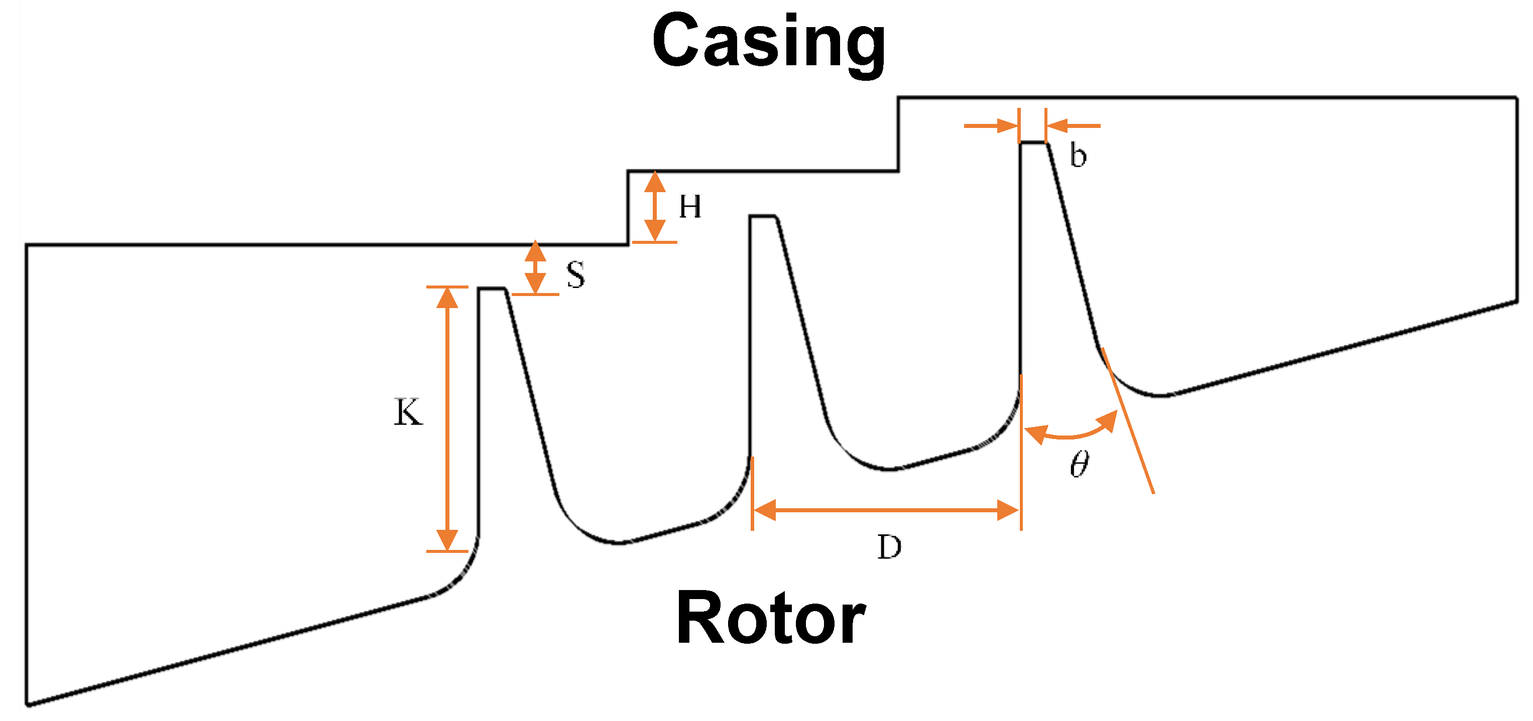
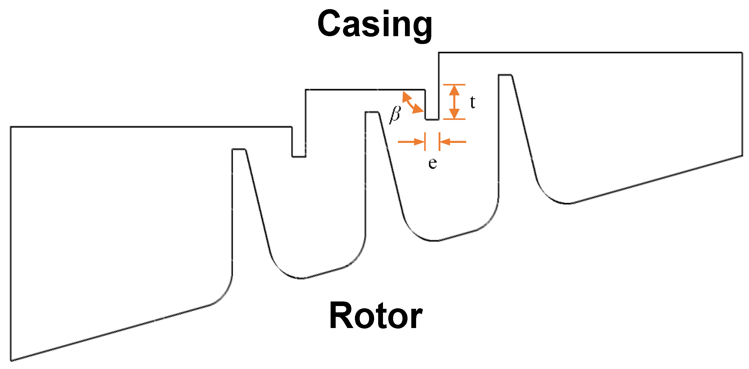
2.1. Seal Geometry
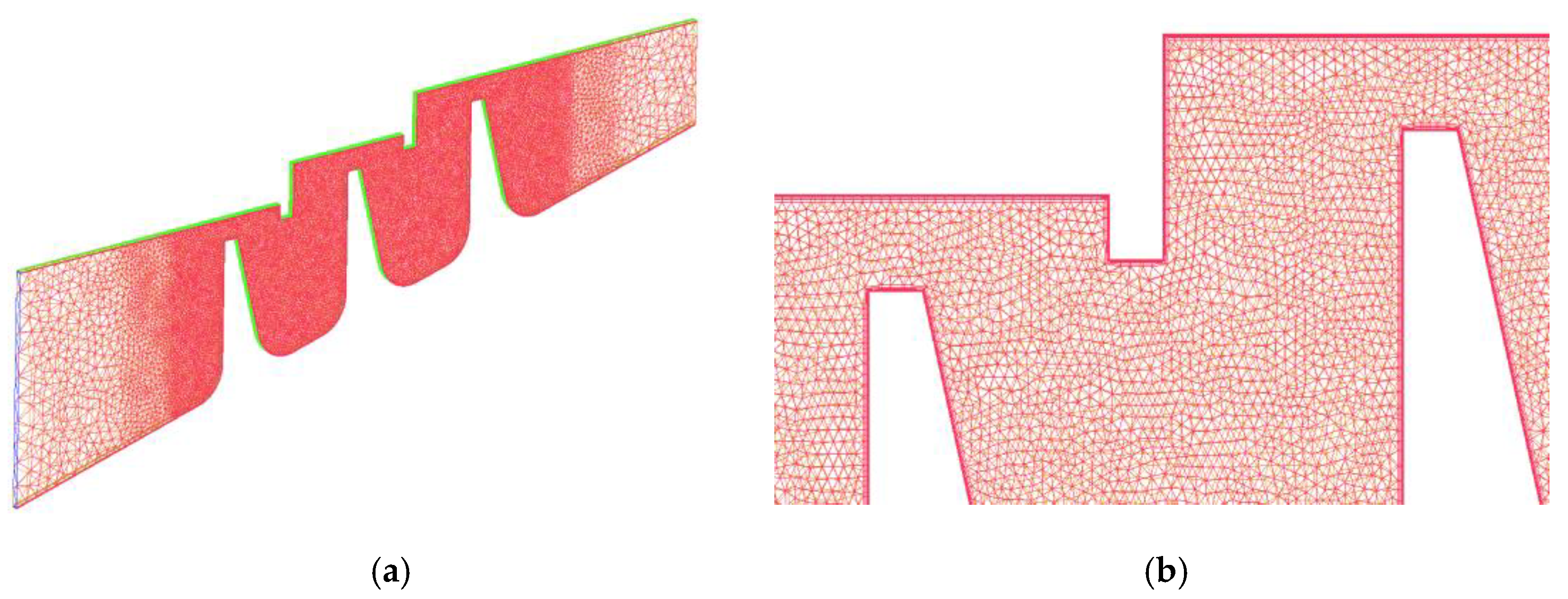
2.2. Numerical Approach
3. Results and Discussion
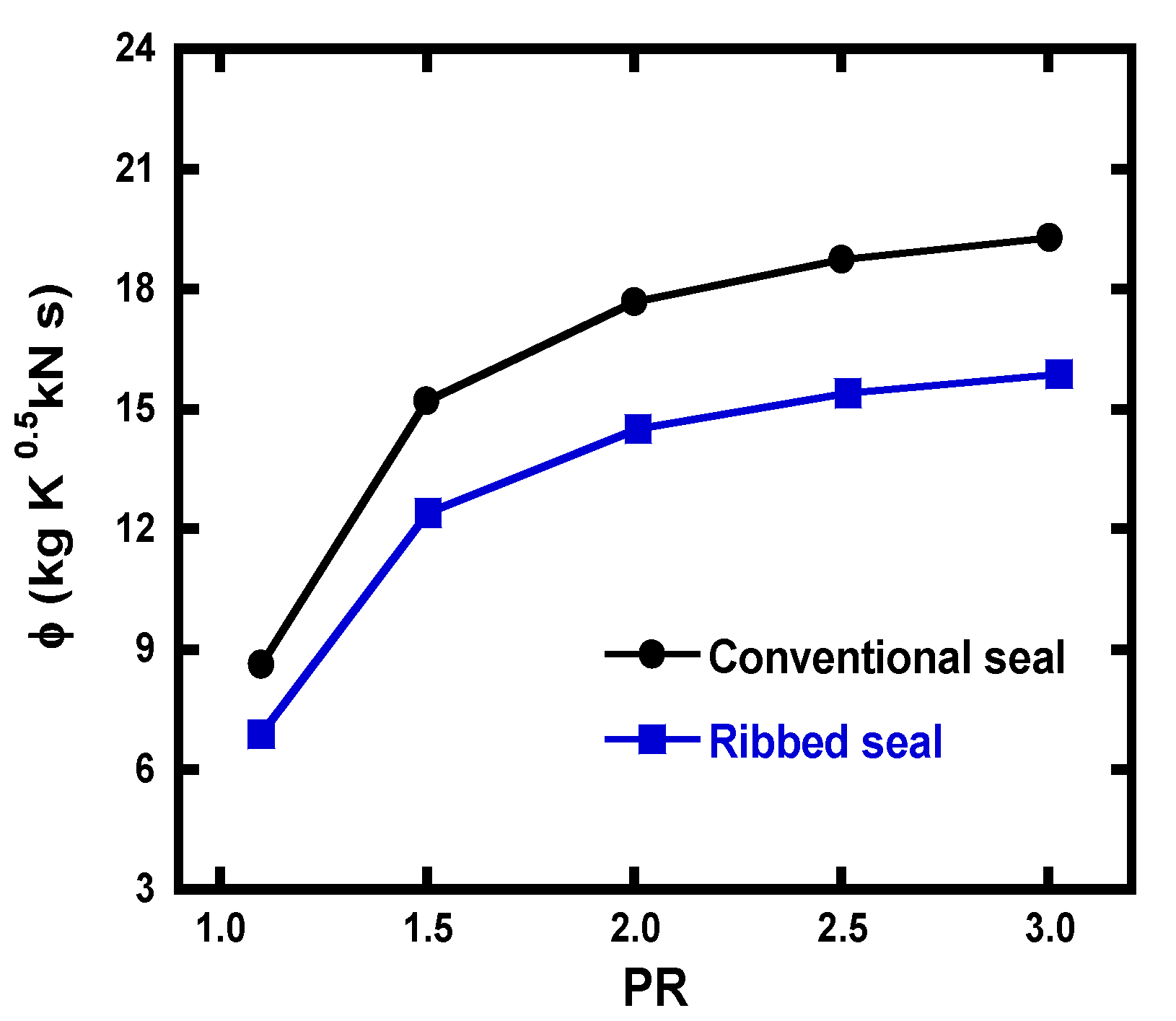
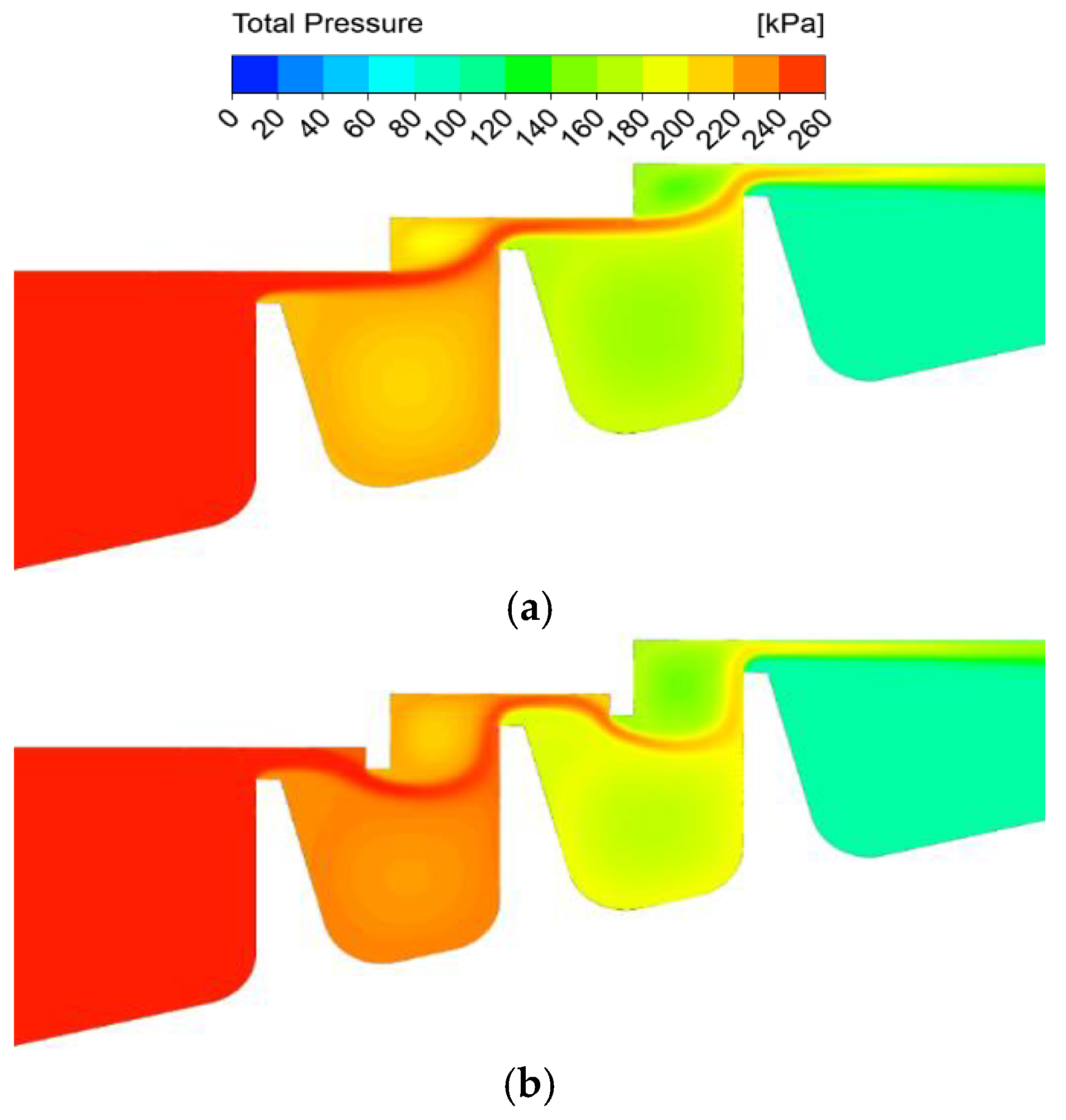
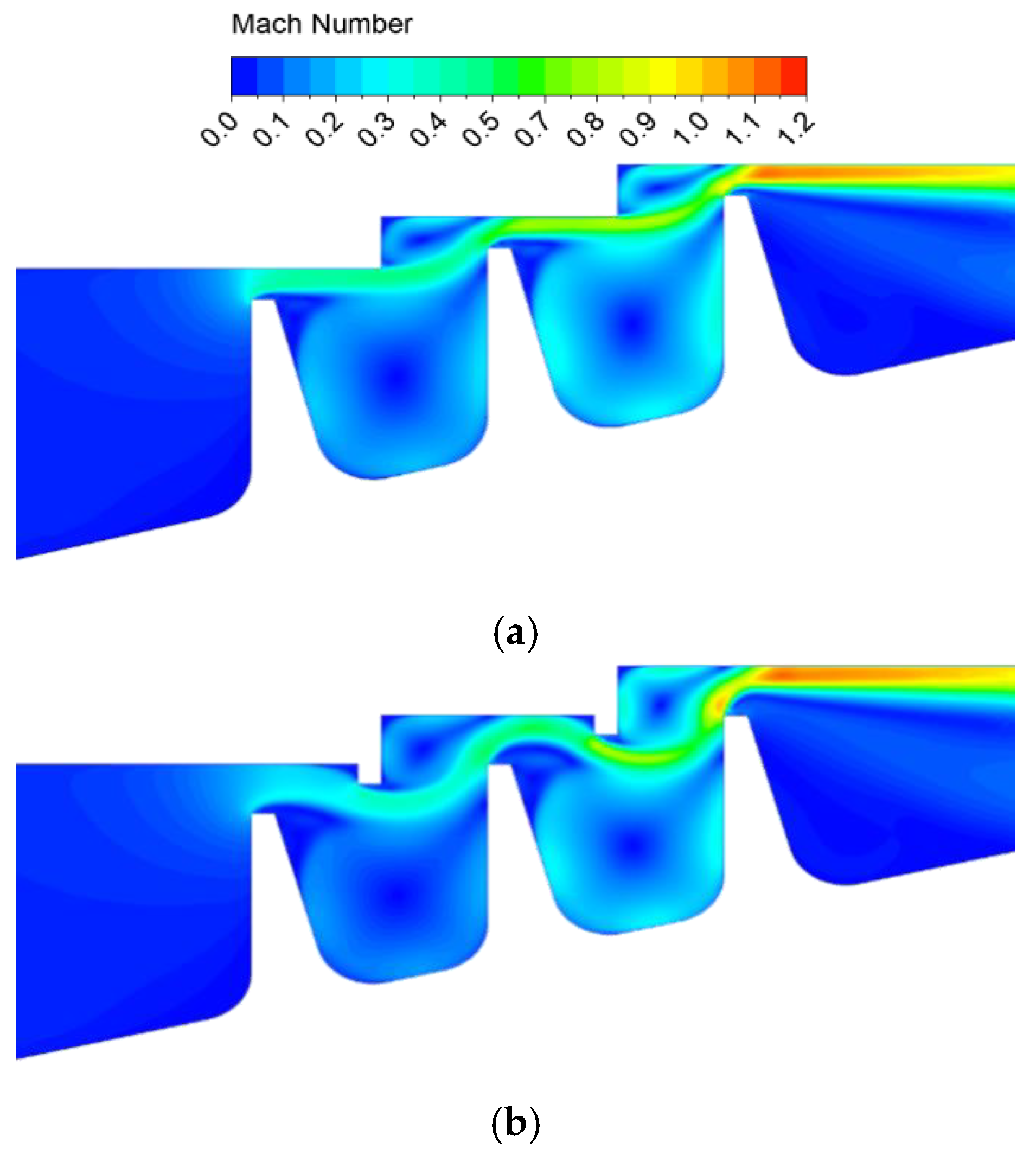
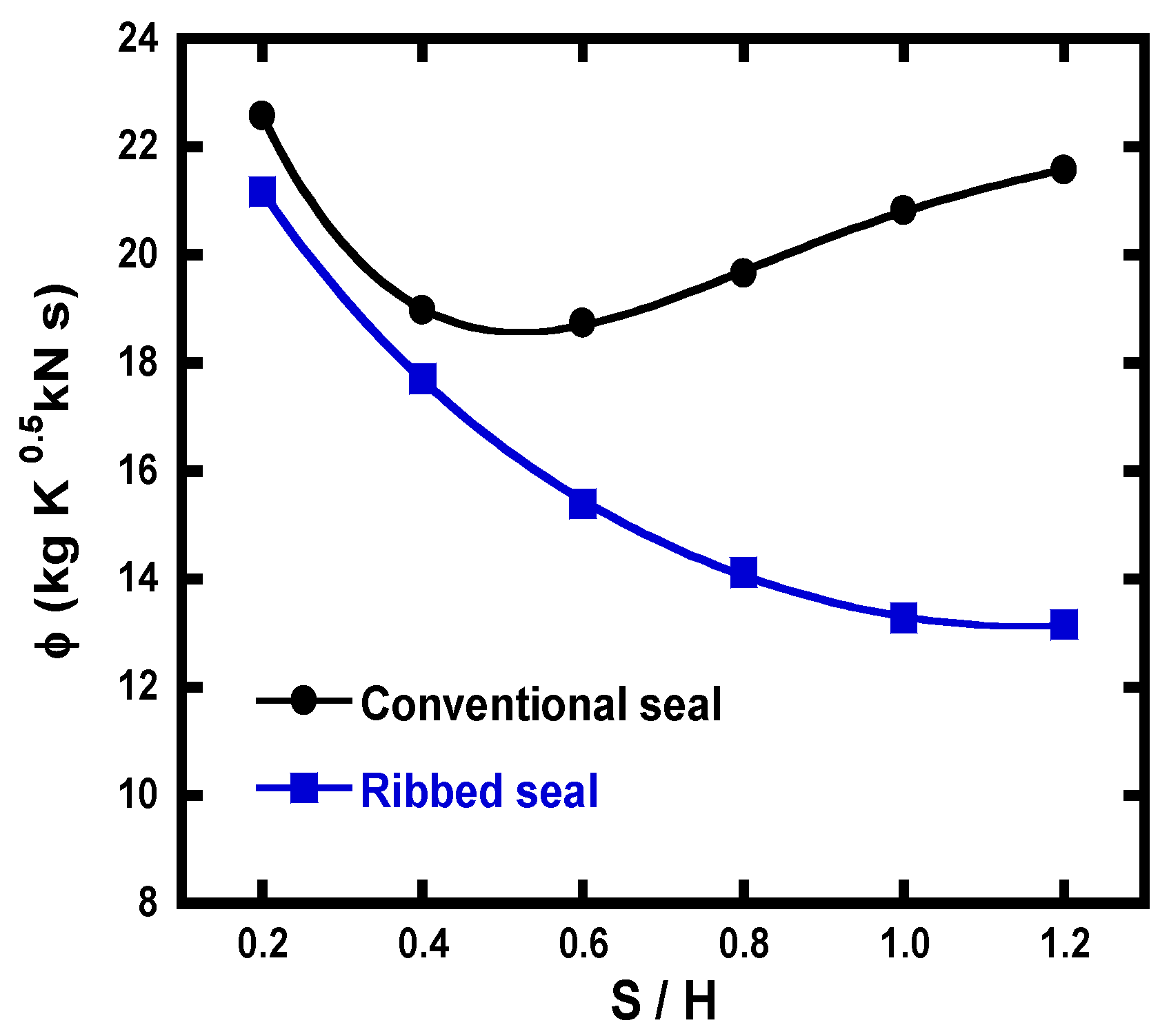
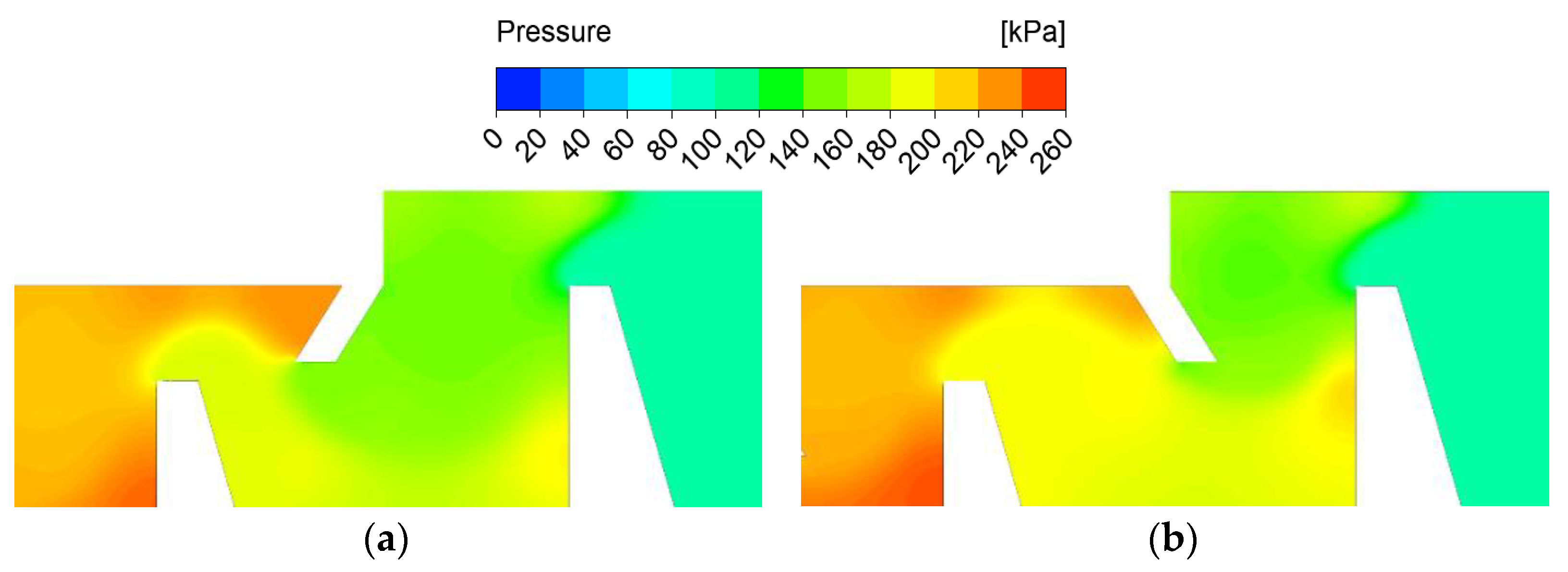
3.1. Comparison of Leakage Characteristics of Conventional and Ribbed Seal
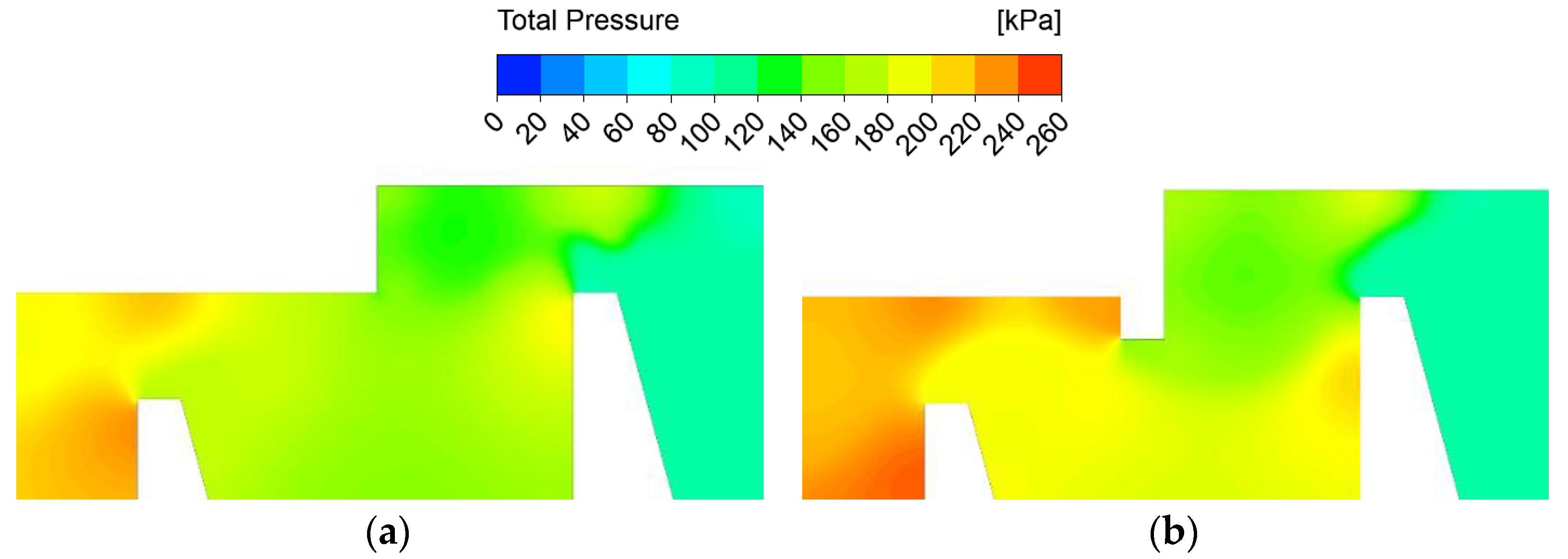
3.2. Parametric Study on the Effect of Rib Geometries
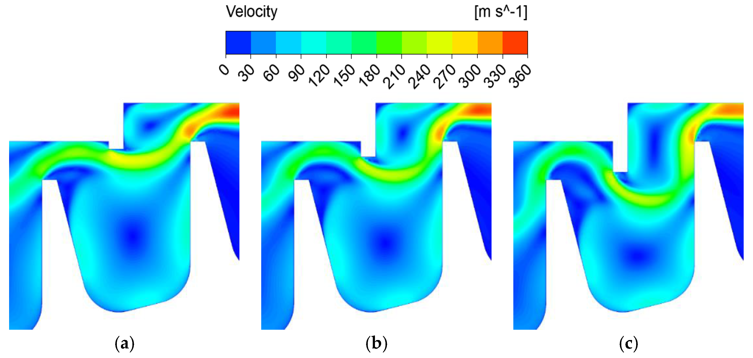
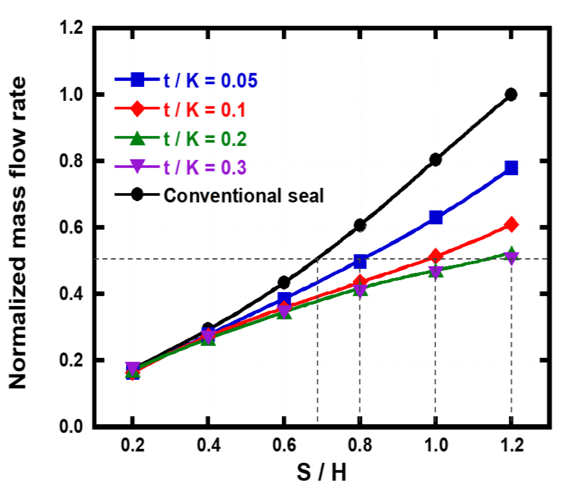
3.2.1. Rib Height
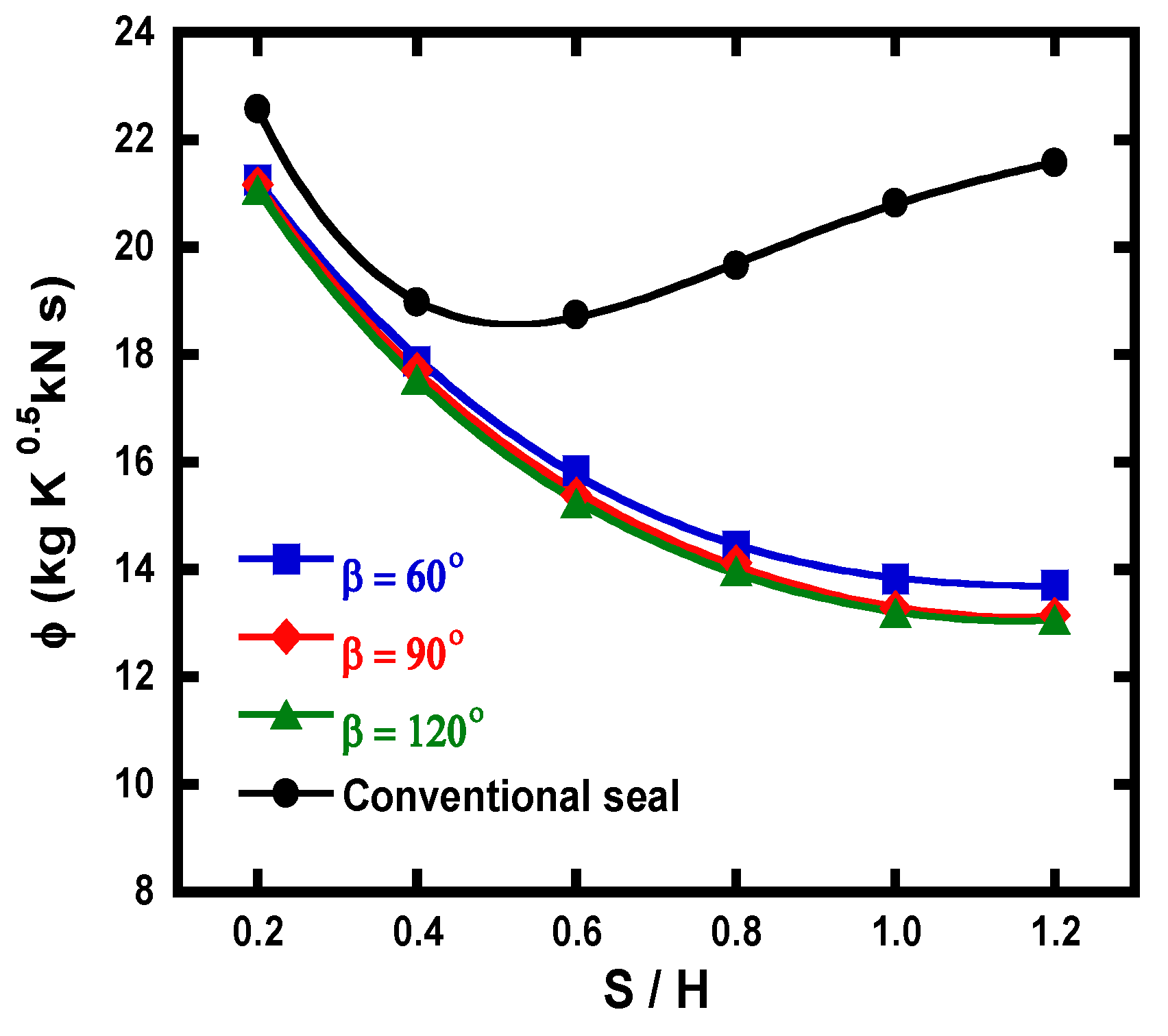
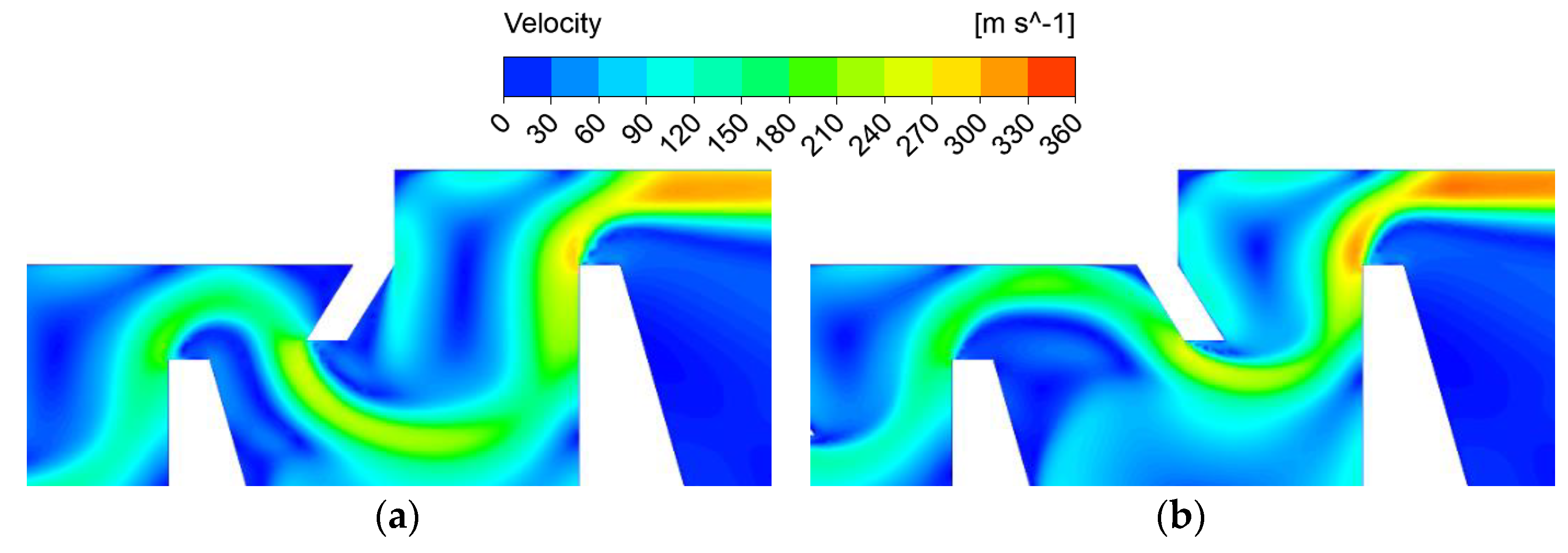
3.2.2. Rib Inclination Angle
4. Conclusions
- (1)
- It was confirmed that the leakage performance of the ribbed seal is better than that of the conventional seal at all clearance sizes (when S/H = 1.0, the flow function is up to 42.6% lower in comparison to the conventional seal). Also, unlike the conventional seal, in which the tendency of the flow function changes as the clearance increases, the flow function of the ribbed seal continuously decreases as the clearance increases. This happens because the added rib changes the flow layer direction, causing a continuous collision between the flow layer and the tooth as clearance increases.
- (2)
- The flow function of the ribbed seal is affected by the rib height (t/K) and rib inclination angle (β), and at almost all S/H, the leakage performance improves as both design parameters increase (when S/H = 1.0, the flow function is 10% lower at t/K = 0.3 and 0.6% lower at β = 120° in comparison to the reference value t/K = 0.1, β = 90°). Also, the larger the size of the rib height and rib inclination angle, the larger the difference in the flow function is between the conventional seal and the ribbed seal. Both design parameters have little effect on the flow function when S/H is very small, but as S/H gradually increases, changes in the flow function occur. Also, it was confirmed that the change in the rib height had a much greater influence on the leakage characteristics than the rib inclination angle. The influence of the rib inclination angle becomes larger when the size of the rib height is large.
- (3)
- The most important advantage of the ribbed seal is that the leakage flow can be greatly reduced by adding very small ribs to the casing when a target seal clearance is kept the same as in the conventional seal. Reduction of leakage flow not only improves the sealing performance but also contributes to the improvement of the performance of the entire gas turbine. Another important point is that the actual operating clearance could be much larger while maintaining the same leakage flow rate compared to the conventional seal. This is a definite advantage in the viewpoint of the turbine design, which could lessen the possibility of tip/casing rubbing while maintaining high turbine performance. One possible practical concern could be the increase of manufacturing complexities due to the addition of the ribs. However, because labyrinth seals with more complex geometries such as interlocking seals with staggered teeth have already been used, it would be quite possible to realize the ribbed seal.
Author Contributions
Funding
Institutional Review Board Statement
Informed Consent Statement
Conflicts of Interest
Nomenclature
| Throat area (m2) | |
| Tooth-tip thickness (mm) | |
| Pitch (mm) | |
| Rib thickness (mm) | |
| Step height (mm) | |
| Tooth height (mm) | |
| Specific heat ratio | |
| Mass flow rate (kg/s) | |
| Number of teeth | |
| Total pressure (kPa) | |
| Static pressure (kPa) | |
| Pressure ratio | |
| Gas constant (kJ/kg·K) | |
| Clearance (mm) | |
| Rib height (mm) | |
| Total temperature (K) | |
| Greek letters | |
| Rib inclination angle (degree) | |
| Tooth angle (degree) | |
| Flow function (kgK0.5/kNs) | |
| Subscripts | |
| Contraction | |
| Inlet | |
| Outlet | |
References
- Vermes, G. A fluid mechanics approach to the labyrinth seal leakage problem. J. Eng. Power 1961, 83, 161–169. [Google Scholar] [CrossRef]
- Wittig, S.; Dorr, L.; Kim, S. Scaling effects on leakage losses in labyrinth seals. J. Eng. Power 1983, 105, 305–309. [Google Scholar] [CrossRef]
- Wittig, S.; Schelling, U.; Jacobsen, K.; Kim, S. Numerical Predictions and Measurements of Discharge Coefficients in Labyrinth Seals. In Proceedings of the ASME 1987 International Gas Turbine Conference and Exhibition, Anaheim, CA, USA, 31 May–4 June 1987. [Google Scholar]
- Wittig, S.; Jacobsen, K.; Schelling, U.; Kim, S. Heat transfer in stepped labyrinth seals. J. Eng. Gas Turbines Power 1988, 110, 63–69. [Google Scholar] [CrossRef]
- Waschka, W.; Wittig, S.; Kim, S. Influence of high rotational speeds on the heat transfer and discharge coefficients in labyrinth seals. J. Turbomach. 1992, 114, 462–468. [Google Scholar] [CrossRef]
- Zimmermann, H.; Kammerer, A.; Wolff, K.H. Performance of Worn Labyrinth Seals. In Proceedings of the ASME 1994 International Gas Turbine and Aeroengine Congress and Exposition, The Hague, The Netherlands, 13–16 June 1994. [Google Scholar]
- Zimmermann, H.; Wolff, K.H. Air System Correlations, Part 1: Labyrinth Seals. In Proceedings of the ASME 1998 International Gas Turbine and Aeroengine Congress and Exhibition, Stockholm, Sweden, 2–5 June 1998. [Google Scholar]
- Schramm, V.; Willenborg, K.; Kim, S.; Wittig, S. Influence of a honeycomb facing on the flow through a stepped labyrinth seal. J. Eng. Gas Turbines Power 2000, 124, 140–146. [Google Scholar] [CrossRef]
- Schramm, V.; Denecke, J.; Kim, S.; Wittig, S. Shape optimization of a labyrinth seal applying the simulated annealing method. Int. J. Rotat. Mach. 2004, 10, 365–371. [Google Scholar] [CrossRef]
- Michaud, M.; Vakili, A.; Meganathan, A.; Zielke, R.; Shuster, L.; Terrell, J. An experimental study of labyrinth seal flow. In Proceedings of the International Joint Power Generation Conference Collocated with Turbo Expo 2003, Atlanta, GA, USA, 16–19 June 2003. [Google Scholar]
- Kim, T.S.; Kang, Y.; Moon, H.K. Aerodynamic performance of double-sided labyrinth seals. In Fluid Machinery and Fluid Mechanics; Springer: Berlin/Heidelberg, Germany, 2009; pp. 377–382. [Google Scholar]
- Kim, T.S.; Cha, K.S. Comparative analysis of the influence of labyrinth seal configuration on leakage behavior. J. Mech. Sci. Technol. 2009, 23, 2830–2838. [Google Scholar] [CrossRef]
- Kim, T.S.; Kang, S.Y. Investigation of leakage characteristics of straight and stepped labyrinth seals. Int. J. Fluid Mach. Syst. 2010, 3, 253–259. [Google Scholar] [CrossRef] [Green Version]
- Kang, Y.; Kim, T.S.; Kang, S.Y.; Moon, H.K. Aerodynamic Performance of Stepped Labyrinth Seal for Gas Turbine Applications. In Proceedings of the ASME Turbo Expo 2010: Power for Land, Sea, and Air, Glasgow, UK, 14–18 June 2010. [Google Scholar]
- Hur, M.S.; Lee, S.I.; Moon, S.W.; Kim, T.S.; Kwak, J.S.; Kim, D.H.; Jung, I.Y. Effect of Clearance and Cavity Geometries on Leakage Performance of a Stepped Labyrinth Seal. Processes 2020, 8, 1496. [Google Scholar] [CrossRef]
- Stocker, H.L. Advanced labyrinth seal design performance for high pressure ratio gas turbines. In Proceedings of the ASME 1975 Winter Annual Meeting: GT Papers, Houston, TX, USA, 30 November–5 December 1975. [Google Scholar]
- Stocker, H.L.; Cox, D.M.; Holle, G.F. Aerodynamic Performance of Conventional and Advanced Design Labyrinth Seals with Solid-Smooth, Abradable, and Honeycomb Lands; NASA: Washington, DC, USA, 1977.
- Stocker, H.L. Determining and improving labyrinth seal performance in current and advanced high performance gas turbines. AGARD Conf. Proc. 1978, 237, 13.1–13.22. [Google Scholar]
- Rhode, D.L.; Ko, S.H.; Morrison, G.L. Experimental and numerical assessment of an advanced labyrinth seal. Tribol. Trans. 1994, 37, 743–750. [Google Scholar] [CrossRef]
- Rhode, D.L.; Johnson, J.W.; Broussard, D.H. Flow Visualization and Leakage Measurements of Stepped Labyrinth Seal: Part 1—Annular Groove. In Proceedings of the ASME 1996 International Gas Turbine and Aeroengine Congress and Exposition, Birmingham, UK, 10–13 June 1996. [Google Scholar]
- Vakili, A.D.; Meganathan, A.J.; Michaud, M.; Radhakrishnan, S. An Experimental and Numerical Study of Labyrinth Seal Flow. In Proceedings of the ASME Turbo Expo 2005: Power for Land, Sea, and Air, Reno, NV, USA, 6–9 June 2005. [Google Scholar]
- Soemarwoto, B.I.; Kok, J.C.; de Cock, K.M.; Kloosterman, A.B.; Kool, G.A.; Versluis, J.F. Performance evaluation of gas turbine labyrinth seals using computational fluid dynamics. In Proceedings of the ASME Turbo Expo 2007: Power for Land, Sea, and Air, Montreal, QC, Canada, 14–17 May 2007. [Google Scholar]
- Chougule, H.H.; Ramerth, D.; Ramachandran, D. Low leakage designs for rotor teeth and honeycomb lands in labyrinth seals. In Proceedings of the ASME Turbo Expo 2008: Power for Land, Sea, and Air, Berlin, Germany, 9–13 June 2008. [Google Scholar]
- Zhang, M.; Yang, J.; Xu, W.; Xia, Y. Leakage and rotordynamic performance of a mixed labyrinth seal compared with that of a staggered labyrinth seal. J. Mech. Sci. Technol. 2017, 31, 2261–2277. [Google Scholar] [CrossRef]
- Wróblewski, W.; Frączek, D.; Marugi, K. Leakage reduction by optimisation of the straight-through labyrinth seal with a honeycomb and alternative land configurations. Int. J. Heat Mass Transf. 2018, 126, 725–739. [Google Scholar] [CrossRef]
- Jia, X.; Zheng, Q.; Jiang, Y.; Zhang, H. Leakage and rotordynamic performance of T type labyrinth seal. Aerosp. Sci. Technol. 2019, 88, 22–31. [Google Scholar] [CrossRef]
- Paolillo, R.; Moore, S.; Cloud, D.; Glahn, J.A. Impact of rotational speed on the discharge characteristic of stepped labyrinth seals. In Proceedings of the ASME Turbo Expo 2007: Power for Land, Sea, and Air, Montreal, QC, Canada, 14–17 May 2007. [Google Scholar]
- Rapisarda, A.; Desando, A.; Campagnoli, E.; Taurino, R. Rounded fin edge and step position effects on discharge coefficient in rotating labyrinth seals. J. Turbomach. 2016, 138, 011005. [Google Scholar] [CrossRef]
- Nayak, K.C. Effect of Rotation on Leakage and Windage Heating in Labyrinth Seals with Honeycomb Lands. J. Eng. Gas Turbines Power 2020, 142, 081001. [Google Scholar] [CrossRef]
- ANSYS Inc. ANSYS CFX 19.0; ANSYS Inc.: Canonsburg, PA, USA, 2018. [Google Scholar]
- ANSYS Inc. ANSYS CFX-Solver Modeling Guide; ANSYS Inc.: Canonsburg, PA, USA, 2011. [Google Scholar]
- Menter, F.R. Two-equation eddy-viscosity turbulence models for engineering applications. AIAA J. 1994, 32, 1598–1605. [Google Scholar] [CrossRef] [Green Version]
- Coughtrie, A.R.; Borman, D.J.; Sleigh, P.A. Effects of turbulence modelling on prediction of flow characteristics in a bench-scale anaerobic gas-lift digester. Bioresour. Technol. 2013, 138, 297–306. [Google Scholar] [CrossRef] [Green Version]


| Parameter | Description | Reference Value | Variation Range |
|---|---|---|---|
| N | Number of teeth | 3 | - |
| D/H | Pitch/step height | 4 | - |
| K/H | Tooth height/step height | 4 | - |
| θ | Tooth angle | 15° | - |
| S/H | Clearance/step height | 0.6 | 0.2–1.2 |
| e/b | Rib thickness/tooth-tip thickness | 1 | - |
| t/K | Rib height/tooth height | 0.1 | 0.05–0.3 |
| β | Rib inclination angle | 90° | 60–120° |
| Turbulence Model | Shear Stress Transport (SST) |
|---|---|
| Advection scheme | High resolution |
| Fluid | Air (ideal gas) |
| Pressure ratio | 1.1~3.0 |
| Inlet total temperature | 295 K |
| Outlet static pressure | 101.325 kPa |
| Wall | Adiabatic, no slip |
| Lateral faces | Symmetry |
Publisher’s Note: MDPI stays neutral with regard to jurisdictional claims in published maps and institutional affiliations. |
© 2021 by the authors. Licensee MDPI, Basel, Switzerland. This article is an open access article distributed under the terms and conditions of the Creative Commons Attribution (CC BY) license (https://creativecommons.org/licenses/by/4.0/).
Share and Cite
Hur, M.-S.; Moon, S.-W.; Kim, T.-S. A Study on the Leakage Characteristics of a Stepped Labyrinth Seal with a Ribbed Casing. Energies 2021, 14, 3719. https://doi.org/10.3390/en14133719
Hur M-S, Moon S-W, Kim T-S. A Study on the Leakage Characteristics of a Stepped Labyrinth Seal with a Ribbed Casing. Energies. 2021; 14(13):3719. https://doi.org/10.3390/en14133719
Chicago/Turabian StyleHur, Min-Seok, Seong-Won Moon, and Tong-Seop Kim. 2021. "A Study on the Leakage Characteristics of a Stepped Labyrinth Seal with a Ribbed Casing" Energies 14, no. 13: 3719. https://doi.org/10.3390/en14133719
APA StyleHur, M.-S., Moon, S.-W., & Kim, T.-S. (2021). A Study on the Leakage Characteristics of a Stepped Labyrinth Seal with a Ribbed Casing. Energies, 14(13), 3719. https://doi.org/10.3390/en14133719