1. Introduction
In order to ensure compliance with the increasingly stringent emissions targets being levied by legislators around the world, the uptake of the concept of engine downsizing (as well as additional complementary technologies such as Miller valve timing) in the automotive sector is becoming increasingly prevalent. From the perspective of the turbocharger, these strategies place additional demands upon enhancing compressor performance and stability at low mass flow-operating conditions [
1].
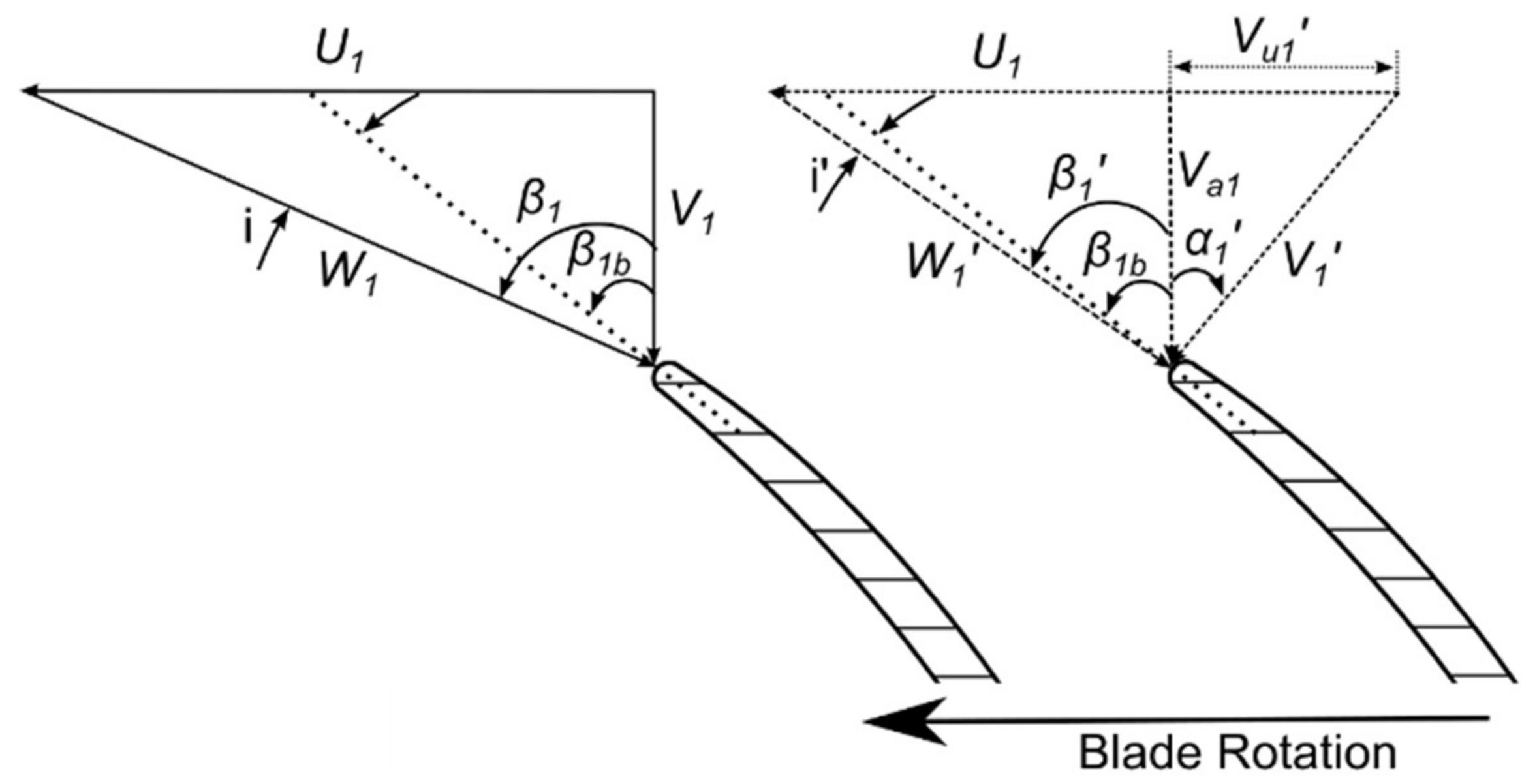
One approach to achieve this goal that is common in larger scale applications is the application of positive pre-swirl (introduction of a non-zero circumferential velocity component,
Vu1, in the same direction as impeller rotation) at compressor inlet through the use of inlet guide vanes. The benefits of this approach are well established, and can be understood through examination of the impeller inlet velocity triangles depicted in
Figure 1.
For automotive turbocharging applications, the expected improvements can be summarized as follows. First, the improvements in compressor efficiency can be expected at low mass flow rates due to the alleviation of incidence-based losses, as illustrated in
Figure 1. A previous study utilizing an automotive turbocharger compressor [
2] cited up to a 3.0%pt improvement in efficiency at a pressure ratio of 2.5 through the application of pre-swirl. Second, the possibility to extend the compressor surge margin is a particularly attractive benefit. However, due to the relatively modest pressure ratios of automotive turbocharger compressors, it has been recognized that high levels of swirl are required to achieve a tangible improvement (60–70° @ PR < 3.0) [
3]. Finally, application of pre-swirl has been demonstrated to offer improved transient response from the turbocharger, and consequently, reduced engine time-to-torque figures (TtT). Application of pre-swirl effectively unloads the compressor (as is illustrated by the Euler turbomachinery equation depicted in Equation (1)), allowing a greater proportion of turbine power to be utilized to accelerate the rotating assembly [
4].
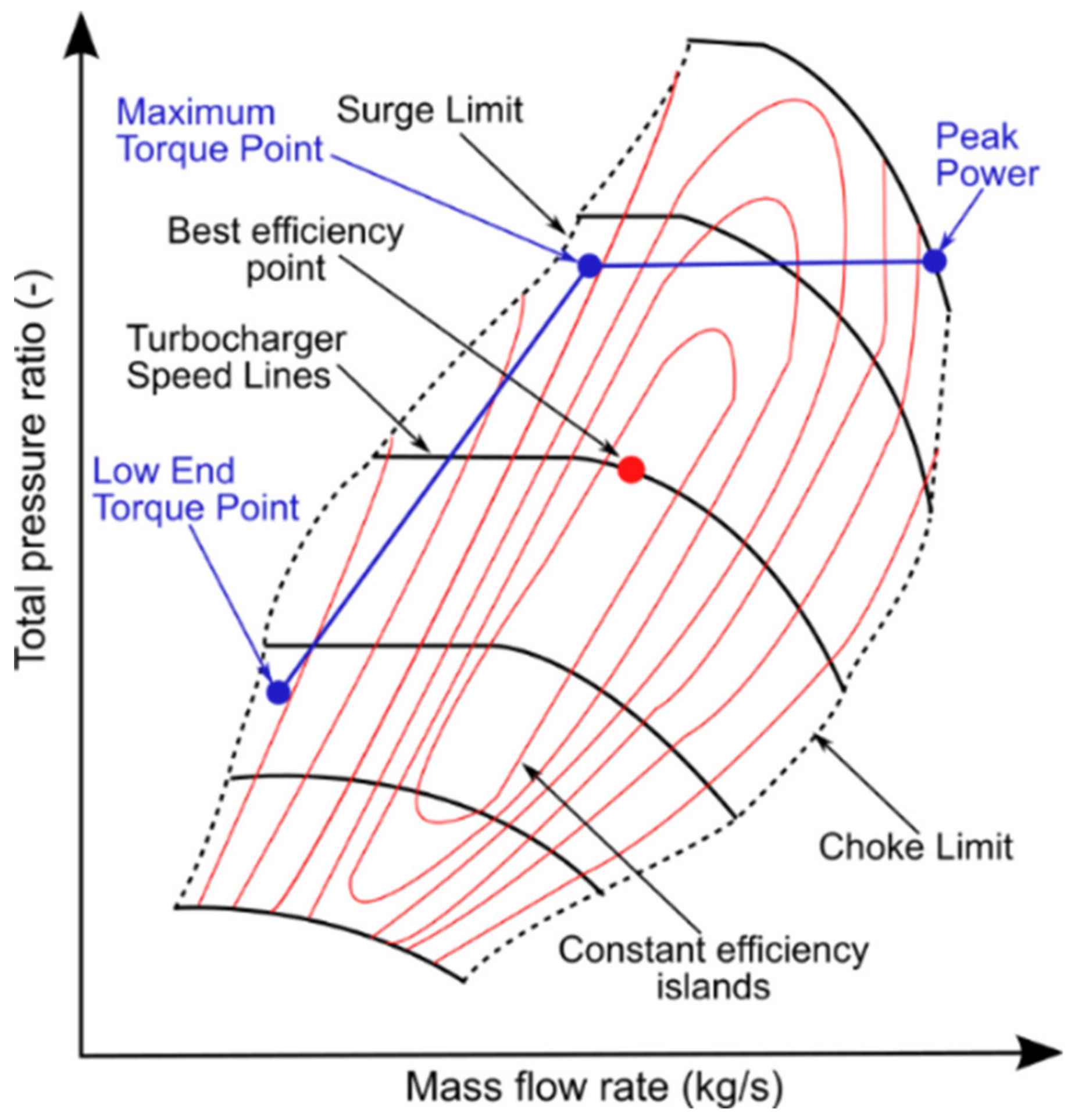
In spite of the above mentioned benefits, the uptake of inlet guide vane (IGV) systems (either fixed or variable) in automotive turbocharging applications has been very limited. The nature of the requirements imposed on the compressor stage necessitate a very wide operating range, which creates significant issues for the application of pre-swirl. This notion is explored further in
Figure 2, which illustrates a typical engine full load line overlaid on an exemplar compressor map.
It is readily apparent from examining
Figure 2 that while improvements in compressor performance and stability are a current focal point for research, advancements in this area cannot come at the cost of reduced performance in other regions of the operating map. The three key engine-operating conditions illustrated span the full width of the compressor-operating range, and hence it is not possible to sacrifice one area of the map to gain at another. This notion of sacrifice underpins the limited uptake of such technologies for this application, as while application of positive pre-swirl has benefits toward surge, it is very detrimental toward the choke side of the map. At high mass flow rates, intolerably large reductions in compressor efficiency (arising from increased incidence losses) and choking mass flow rate [
2,
5] are to be expected. Ultimately then, an ideal IGV system should be capable of delivering high swirl angles for low mass flow-operating conditions, and zero swirl toward choke. While this is clearly an impossibility from a fixed geometry system, unfortunately, even moving to a variable inlet guide vane (VIGV) configuration does not entirely overcome this limitation. A comparatively recent study [
6] evaluated the feasibility of a number of advanced VIGV concepts for use with an automotive turbocharger compressor (including variable vane camber), but ultimately could not deliver meaningful improvements in performance.
Aside from the aforementioned wide operating range of automotive turbocharger compressors, one particular consequential flow phenomenon could also act as a limiting factor for the success of inlet swirl devices. Recent investigations [
7,
8] have highlighted that, at inlet in particular, shroud side recirculation can occupy up to 60% of the passage for near-surge-operating points, and remain a prominent flow feature for a large proportion of the compressor-operating range. As this region of recirculation can extend for a number of pipe diameters upstream of the inducer, the resulting complex interaction involves not only the flow emanating from an IGV system, but also the reverse flow from the impeller impinging on the IGV’s [
9].
As a consequence of these requirements, the current study sought to develop a device capable of efficiently generating large swirl angles at low mass flow rates, while also being capable of generating zero pre-swirl for operation close to choke. The chosen solution involved positioning an electrically driven axial fan upstream of a standard automotive turbocharger compressor stage. This concept was first presented in a patent document by Daimler [
10], however, despite apparently showing potential, the authors are not aware of it being investigated beyond an initial feasibility study. This architecture is advantageous from the perspective that the fan speed can be controlled completely independently of the turbocharger shaft speed, allowing the upstream axial fan to act as an active inlet swirl control device with the potential to utilize the work input to overcome a proportion of the losses typical of IGV systems. Furthermore, it was envisioned that the capability to actively interact with the impeller inlet recirculation would yield the potential to suppress its extent and hence contribute to further enhancing the compressor stability [
3].
A final point worth addressing is the advantage of using an electric motor to generate pre-swirl rather than directly contributing to boost pressure. While electrically driven superchargers are becoming more commonplace, the cost and complexity of such systems is high. By comparison, an electric motor used for pre-swirl generation can be of much lower power, contributing to a less expensive, more compact system that is more straightforward to integrate with an existing turbocharger and vehicle architecture. Crucially when considering the aims of this study, it is also worth noting that two-stage systems do not offer improvements in compressor-operating range.
2. Methodology
Prior to engaging in a detailed description of the design methodology employed, it is worth first outlining the constraints involved. The primary aim from the commencement of the investigation was to arrive at a configuration that could be practically tested and feasibly implemented (with reasonably limited further design effort) into a real world application. As a part of this, and to control costs at the initial prototyping stage, it was deemed that the electrical motor had to be a readily available “off the shelf” unit. Consequently, due to the relatively large dimensions of suitable production electric motors, packaging of the system was not considered an overarching limitation. However, the use of a very large, slower rotating fan to generate the swirl was not deemed as being feasible in this case.
Regarding the choice of base compressor stage, in keeping with the desire to utilize production components where possible, a typical automotive turbocharger was chosen from a gasoline engine application. The compressor impeller comprised of six main and six splitter blades, with D
2 = 51 mm and β
2b = −44.0°. In order to focus the design effort on the most important regions of compressor operation, and to streamline the presentation of results and subsequent analysis, six key operating points of interest were defined, as illustrated in
Figure 3. The designation describing each operating point can be decomposed in the following fashion; “120k” represents a turbocharger shaft speed of 120,000 rpm, with “NS,” “DP,” and “NC” representing near-surge, design point, and near choke operation respectively.
2.1. Modelling
The aerodynamic modelling work undertaken comprised of 1-D fan design, as well as 3-D CFD design and performance prediction of the coupled centrifugal stage and axial fan. The 1-D design phase permitted selection of appropriate initial fan design parameters, and highlighted the need for a part span configuration to allow generation of the required pre-swirl levels while minimizing the impact on the choke flow capacity of the complete compression system. This point will be clarified in the coming section, however the unavoidable (and significant) interaction between the impeller inlet recirculation and the fan quickly dictated that CFD analysis was the only meaningful way to proceed.
In tandem with the aerodynamic design of the fan, a simplified brushless direct current (BLDC) electric motor model was developed and utilized to allow the capabilities of the different available electric motors to be factored in during the selection of fan geometry and operating points. The dimensions of the electric motor also played a significant role in the aerodynamic design phase, with the relatively large casing diameters of available electric motors necessitating an undesirably large fan hub diameter (36 mm). With the mean radius of the fan blades being somewhat larger than that of the compressor inducer, it was however anticipated that the swirl generated by the fan would be intensified due to conservation of angular momentum considerations, thus reducing the swirl delivery requirement of the fan.
Having settled on a geometry specification, the design was progressed through FEA modelling of the fan and spinner to ensure structural integrity at the operating points derived from the aerodynamic study. The constraints involved dictated something of an iterative approach to the above modelling work, however it is presented herein in terms of the logical, high level, global work flow.
CFD Methodology
The approach used for the baseline CFD configuration was that as presented by Stuart et al. [
8], representing a typical single passage analysis comprising two stationary domains (inlet and vaneless diffuser) and one rotating domain (impeller). Consequently, for the sake of brevity, the current publication will not enter into a detailed description of this method. However, a schematic representation of the setup employed has been included in
Figure 4 for completeness sake. In each case, stage performance was defined from measurement planes coincident with the inlet and vaneless diffuser exit (MP0 to MP3).
The first piece of analysis undertaken using the CFD setup was to evaluate the potential benefits of inlet swirl at the previously defined operating points of interest. In order to define a “best case scenario” for this evaluation, a uniformly distributed non-zero theta component was added to define the flow direction at the inlet boundary, thus signifying a condition whereby the pre-swirl could be generated on an entirely loss free basis. From this it was determined that the optimum swirl levels to maximize the compressor efficiency were 60° at the NS points, 20° at the DP points, and 0° at choke. The overall impact of the inclusion of swirl is presented and discussed toward the conclusion of this section.
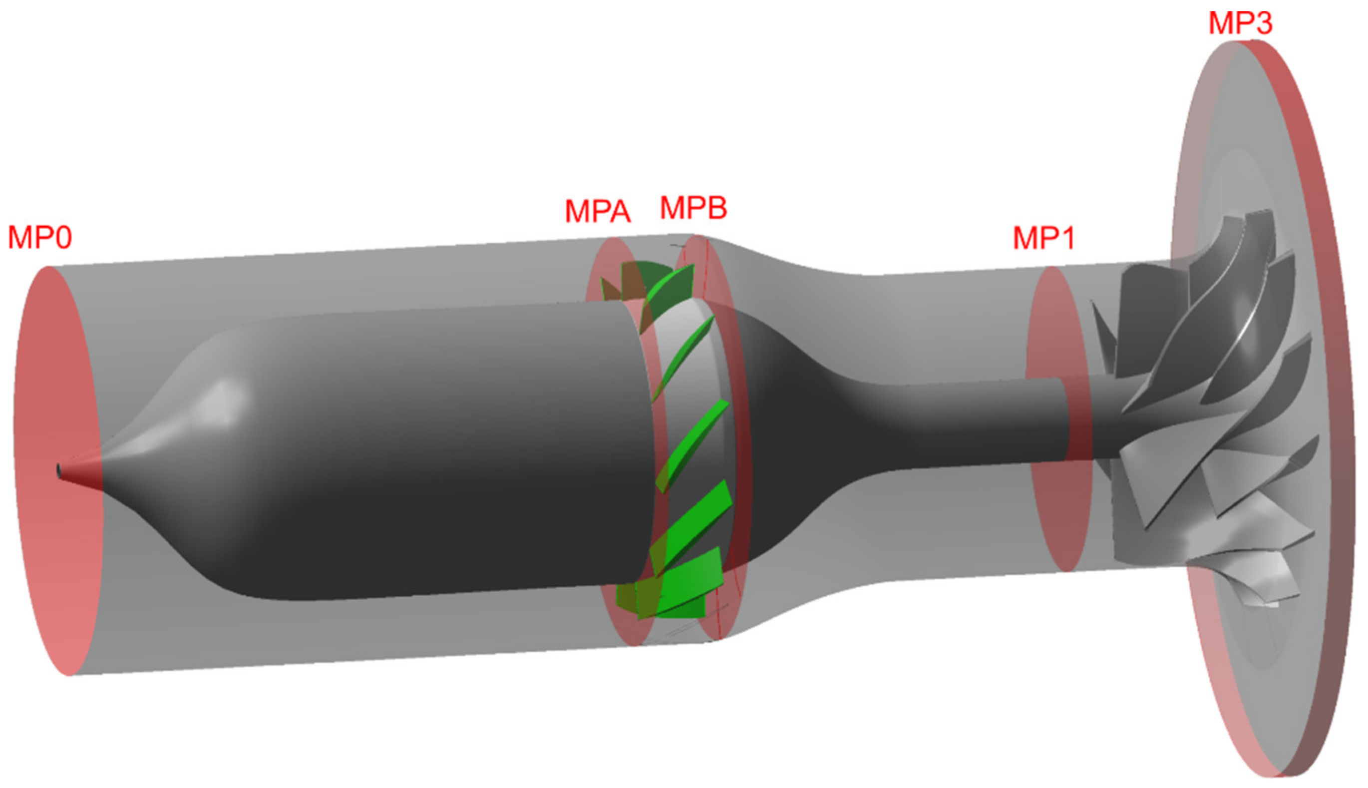
Having understood the magnitude of the theoretically achievable benefits available, the next step was to evaluate how closely it would be possible to replicate these results using the proposed concept. In order to facilitate this, the stationary inlet domain (represented by “S1” in
Figure 4) was replaced with a single passage-rotating domain containing the fan geometry. All other aspects of the model remained unchanged in comparison to the baseline configuration. The new inlet domain was generated in ANSYS BladeGen and meshed in ANSYS TurboGrid (in both cases utilizing version 17.2 of the software), requiring approximately three million cells to satisfy mesh quality and grid independence requirements. The resulting domain setup is illustrated in
Figure 5, which highlights the different measurement planes used to define the performance of both the fan and the overall system, as well as the treatment of the different walls to render certain regions effectively stationary as necessary. To further enhance the clarity of presentation,
Figure 6 then depicts a full annulus rendering of the complete computational domain. It is worth re-emphasizing that this is for illustration only, as a single passage methodology was employed.
Figure 5 illustrates the “unconventional” inlet geometry brought about by the large diameter of the chosen electric motor. While this posed challenges in ensuring that any total pressure losses arising from the change in section were minimized, it did facilitate the use of slightly lower fan speeds to generate a given level of swirl at the compressor inlet (due to conservation of angular momentum considerations). The profile of the resulting “S-duct” connecting the fan to the impeller was optimized to minimize the total pressure losses, while the extended fan spinner was identified as an important inclusion early in the aerodynamic design process. Upon removal of this feature, CFD-predicted stage efficiency was witnessed to reduce by up to 4%pts due to reduced flow guidance.
Figure 6 demonstrates the relatively large axial separation between the fan and the centrifugal impeller. This decision was taken during the CFD design process for two reasons. First, in a more closely coupled arrangement, the interaction between the fan and the shroud side impeller inlet recirculating flow proved to be beyond what the steady single passage CFD methodology could rationalize. Consequently, in order to allow the solver to achieve converged solutions (particularly at lower mass flow-operating conditions), the axial separation was increased as shown. Second, reducing (but not eliminating) the direct interaction between the fan and impeller inlet recirculation made it feasible to evaluate the fan performance in isolation.
It is worth explicitly noting at this stage that the intention for the CFD study was not to gain direct insight into the potential for surge margin extension; one cannot expect a steady single passage analysis to accurately predict the onset of a fundamentally unsteady, system dependent phenomenon such as surge [
5]. However, the ability to generate the required levels of pre-swirl (determined from the literature review) was theorized to be sufficiently indicative for this stage of the design process. Consequently, the primary objective for the CFD was to optimize fan performance within the existing confines of the compressor map (while maintaining the ability to generate large swirl angles for surge margin extension, and also satisfying the operational limits of the chosen electric motor).
The complete CFD setup, which encompassed details illustrated by both
Figure 4 and
Figure 5, was then utilized to evaluate the fan speed that maximized the overall compressor efficiency (MP0 to MP3) for each of the six operating points of interest. In tandem with this, the previously described BLDC motor performance model was utilized to ensure that the chosen operating points were capable of being attained by the electric motor. A summary of the final fan dimensions is presented in
Table 1, with the corresponding operating points outlined in
Table 2. It is worth emphasizing again that the fan was a part span design, with the blades occupying the lower 60% of the inlet section span.
2.2. Results
The results of the aforementioned comparisons are presented in
Figure 7 for the predictions of compressor pressure ratio and efficiency. In order to maximize the clarity of the results, the data for all six operating points have been presented as a change relative to the baseline configuration depicted in
Figure 4. It is worth noting that the apparent absence of “Baseline with Inlet Swirl” data for the choke points is representative of the fact that the ideal swirl value at these operating points was equal to zero.
Examining the pressure ratio prediction within
Figure 7 first of all, it is readily apparent that the application of inlet pre-swirl, even when generated on a loss free basis, results in a decrement in total pressure ratio across the stage. This is of course not an unexpected result; the Euler turbomachinery equation (as depicted in Equation (1)) clearly dictates that positive pre-swirl at inlet results in a reduction in the specific work input of the stage, and hence the expected total pressure rise.
Looking at performance with the fan in particular, it is clear that while the fan does add work to the flow, it is a very modest contribution, and with the exception of the 160k_NS point, it was not sufficient to overcome the swirl-based decrement in impeller work input. Unfortunately, the modest amount of pressure rise across the fan was nullified by losses through the S-duct, which were an unavoidable consequence of the relatively large electric motor casing diameter (and correspondingly large fan hub diameter). In spite of the concession to utilize a part span fan design, this issue clearly increases in prominence as mass flow rate increases, with the choke points in particular exhibiting the significant drops in stage total pressure ratio (6.1% and 7.8% for 120k_NC and 160k_NC respectively). Ultimately, it was found that while increasing the fan speed could help to overcome the pressure losses through S-duct at higher mass flow rates, the intolerance of the centrifugal stage to the additional pre-swirl generated resulted in an even more significant stage performance decrement, and hence the operating points illustrated in
Figure 7 represent the best compromise. Away from the near choke points however, it was promising to witness that the reductions in stage total pressure ratio were comparable to what was witnessed in the baseline case with swirl applied as an inlet boundary condition.
Moving onto the efficiency comparison, it is worth first clarifying the meaning of the additional data field presented in
Figure 7. The “Axial Fan without ΔT0” field represents the stage efficiency evaluated without including the total temperature rise (work input) across the fan, i.e., in reference to
Figure 4 and
Figure 5:
This efficiency definition relates to a situation whereby the energy required to drive the fan is available “for free.” From a practical perspective, this is not unreasonable with the excess of electrical energy available on modern automotive installations (48 V mild hybrid systems etc.,) and the relatively low power values required in this application. The results are therefore comparable to the idealized “Baseline with Inlet Swirl” case. However, while the work input from the fan was excluded in this definition, it was not feasible to accurately isolate the total pressure loss through the S-duct in CFD. While the work input could be isolated by evaluating the total temperature at Measurement Plane (MP) B, completion of the same exercise with total pressure necessitated evaluation at MP1. Unfortunately, with the large amounts of inlet recirculation present, it was not possible to extract a representative total pressure value at MP1. As a result, while the “Axial Fan without ΔT0” results should approach those depicted by the idealized baseline with inlet swirl case, they do not replicate the idealized case exactly. While not particularly relevant at the lower mass flow-operating points (which exhibited a relatively minor S-duct-derived total pressure decrement over the idealized case), this becomes a point that is necessary to bear in mind at higher mass flow-operating points where the large motor diameter (and resulting S-duct) caused significant total pressure losses.
Focusing on the efficiency results presented in
Figure 7 themselves then, the benefit of inclusion of the fan at the near-surge points is readily apparent. At the low mass flow rate-operating points, improvements in efficiency of 1.4%pts and 2.4%pts for 120k_NS and 160k_NS were witnessed, respectively. Removal of fan work caused these to increase to 5.7%pts and 5.2%pts respectively, successfully matching (or exceeding in the case of 120k_NS) the idealized baseline with inlet swirl case. Consequently, it was clear that the fan was successfully bringing about improvements close to the surge line.
In spite of the demonstrated limitations with the system toward the choke side of the operating range (which are recognized to originate predominantly from the large diameter motor required for the prototype system), it was hypothesized at this point that the predicted efficiency improvements at low mass flow rates were sufficient to justify proceeding through to experimental validation. Furthermore, while the CFD results indicated a tangible interaction between the fan and the impeller inlet recirculation region (demonstrating reduced inlet recirculation extent when operating with the fan, which has been correlated to improved compressor stability [
3]), experimental testing provides the only means of truly understanding the potential of the device to extend the compressor surge margin.
3. Development of Experimental Hardware
Having demonstrated sufficient potential from the system during the numerical modelling section to warrant undertaking experimental validation, the first step was to consider the most appropriate means of representing the simulated configuration during physical testing.
The intention from the outset was to mimic the configuration used in the CFD study as closely as possible. Consequently, all of the main geometric parameters were maintained, including the meridional profile of the inlet duct and the axial distance between the axial and radial stages. The design of the axial fan and spinner targeted minimizing mass; the chosen electric motor originated from a remote control car application (Fusion Exceed 3.5T), and hence the standard bearing system was never intended to support a large overhung mass. A static structural analysis was conducted in ANSYS Mechanical 17.2 to evaluate the structural integrity of the chosen fan and spinner designs. The simulation was conducted at the maximum rotational speed of 90 krpm with no applied aerodynamic loading (very low pressure ratio design), and using 7075-T6 as the chosen material. The results indicated no issues with the design, with adequate safety factors and insignificant deflection values throughout.
In order to try to negate the possibility of encountering any rotor dynamic issues during operation, the motor output bearing cap was modified to permit inclusion of elastomeric dampers, and the fan and spinner were dynamically balanced to an ISO 1940-1 [
11] balance quality grade of 1.0. At the same time, the original motor bearings were replaced with name-brand alternatives, and also periodically replaced during the test program, to try to avoid any issues with bearing failure during operation.
Regarding other aspects of the hardware design, as many interstage measurements were included as possible to facilitate scrutinizing of test data not only in terms of overall stage performance parameters, but also for individual component performance. In all, two interstage static temperature measurements were located 0.57D
1s upstream of the impeller leading edge (at an immersion depth of 8.5 mm from the shroud wall), with 36 interstage static pressure taps distributed throughout the S-duct, as well as at impeller exit. An illustration of the final hardware configuration is presented in
Figure 8, with all of the prototype components having been manufactured in the QUB Engineering Workshop.
4. Experimental Testing Procedure
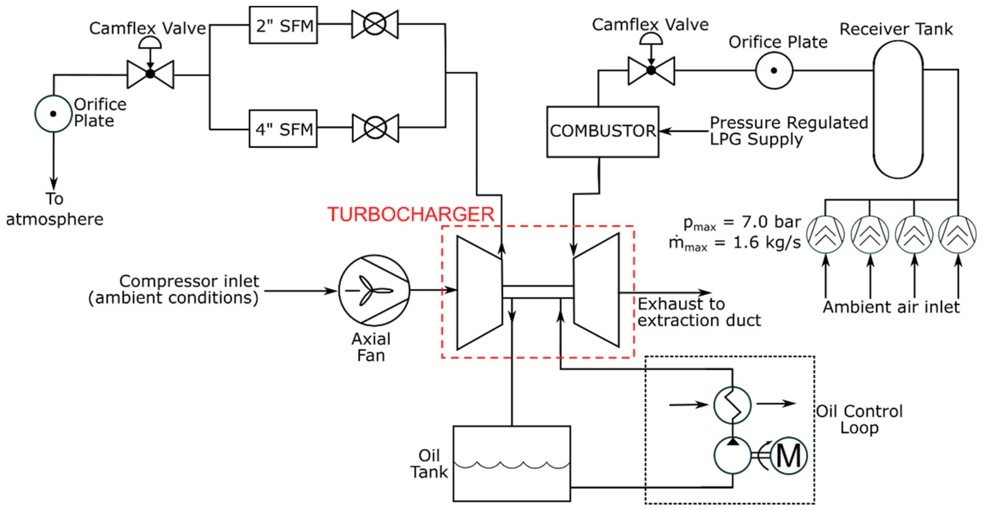
In order to establish confidence in the accuracy of the CFD simulations and gain insight into the ability of the device to extend the stable operating range of the compressor stage, the CFD predictions were compared to those gathered during gas stand testing in QUB. The layout of the test facility for this particular campaign of experimental work is depicted schematically in
Figure 9.
Compressor mass flow measurements were collected using one of the two ABB FS4000-ST4 swirl flow meters (SFM) illustrated in
Figure 9 to an error of less than ±0.5% at reference flow conditions [
12]. Turbine side mass flow rate measurements were gathered using a 3” diameter orifice plate, the readings from which were calibrated against the measurements from one of the aforementioned swirl flow meters across the entirety of the expected operating range. The rotational speed of both the centrifugal impeller and axial fan were measured using two independent Micro Epsilon DZ140 [
13] units which utilize an eddy-current-based measuring system to detect blade passing. Static pressure data were gathered using Druck PMP 4000 Series gauge pressure transducers, delivering readings to an accuracy of ±0.04% full scale [
14]. Compressor interstage temperature values were gathered using 1 mm diameter unshielded T-type thermocouples, while temperature measurements pertaining to overall stage performance on the compressor side of the rig, as well as at turbine discharge, were logged using calibrated BS1904 [
15] Class-A PT-100 resistance thermometers. By comparison, turbine inlet temperatures were gathered using K-type thermocouples. In addition to the above, provision was left to permit live monitoring and logging of the electric motor casing temperature using a surface mounted PT-100. This was deemed to be an essential inclusion for both motor health monitoring and characterization of heat transfer from the motor casing.
In order to minimize the impact of heat transfer on the measured efficiency values obtained from the test rig, steps were taken to control the levels of heat transfer to and from the turbocharger [
8]. With the current data set, a rigorous procedure of thermal matching across the turbocharger was employed at all points to control the internal heat transfer levels (characterized by a maximum variation of ±50 °C between compressor discharge, turbine inlet, and bearing oil inlet temperatures), while the turbocharger was insulated to control the external heat transfer. Furthermore, to ensure comparability between the different tested configurations at the same operating point, all of the key operating parameters were replicated in each case, with a particular emphasis on bearing oil and turbine inlet conditions. The limit of compressor stability was determined through operator experience. Due to the relatively large downstream volume on the test bench, the onset of deep surge was unmistakable. The resulting maximum uncertainty in the total pressure ratio (PR), corrected mass flow rate (ṁ), and isentropic total-to-total efficiency (η) measurements were ±0.08%, ±0.58%, and ±0.15%pts respectively for the six operating points of interest.
Prior to moving onto the results from the experimental testing program, it is worth explicitly clarifying the definition of “stage performance” used henceforth. Within the ensuing discussion of experimental testing results, “stage performance” was measured from compressor upstream stagnation conditions to volute exit. Therefore, with the motor in the inlet flow path, not only was fan efficiency a contributory factor in determining the overall stage efficiency, but heat rejected from the electric motor casing also played a role. To avoid this, consideration was given to mounting the electric motor on the outside of an elbow during the design phase, however the perceived likelihood of rotordynamic issues arising from having to significantly extend the shaft curtailed this idea. Regardless, the potential for heat transfer from the motor casing to impact upon the measured compressor efficiency was evaluated using the motor casing temperature measurements gathered during testing. These demonstrated the potential alterations to measured compressor efficiency to be negligible at all but the lowest mass flow-operating points, and hence are not considered further in this publication.
5. Experimental Results
The experimental results are presented subsequently in two distinct sections; first, evaluation of stage performance with and without the axial fan for the six previously defined operating points of interest. This is then followed by an evaluation of the potential of the device to extend the surge margin of the baseline compressor stage. The data in each case were non-dimensionalized using the maximum value of a given parameter encountered during testing of the baseline configuration.
5.1. Stage Performance
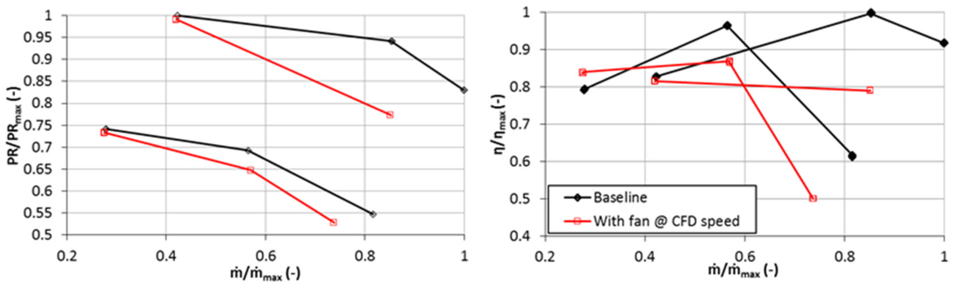
The results from the experimental test campaign for both pressure ratio and efficiency are presented in
Figure 10, depicting the cases for the baseline and with the axial fan operating at the speed values defined as part of the CFD study and listed in
Table 2.
Upon examining
Figure 10, one obvious omission from the data is readily apparent. It was not possible to conduct testing at the 160k_NC point due to a fan overspeed issue. It transpired that, even with the motor turned off (at windmill conditions), the fan speed looked set to exceed 100 krpm. This was beyond the operating limits set during the design process and those of the electric motor, so to ensure safety of the hardware (and considering it is not one of the more critical operating points), the decision was taken to neglect this operating point.
Returning to the results, comparison of with the CFD predictions depicted in
Figure 7 illustrates trends in the experimental data that are effectively exaggerated versions of what was witnessed in the numerical study. While the increase in stage efficiency of 3.0%pts at 120k_NS exceeded expectations, the efficiency decrement present at 160k_NS was unexpected, and lead to a question about whether the CFD had in fact highlighted the most appropriate fan speed values to maximize stage efficiency. Variations in fan speed were tested for the near-surge points, where it was shown for the 160k_NS-operating points that it was possible to recover from a 1.0%pt efficiency drop at a fan speed of 60 krpm to a 0.4%pt increase by increasing the fan speed to 75 krpm. By comparison, at 120k_NS the CFD simulations succeeded in predicting the most efficient speed to operate the fan at. However, increasing fan speed beyond 60 krpm in the test campaign resulted in early onset of surge (an issue which is described in greater detail in the coming section).
Regarding the higher mass flow-operating points, the significant pressure ratio and efficiency reductions can have the same explanation attributed to them as during the CFD study (albeit the reductions in performance, and mass flow capacity for 120k_NC, proved to be more pronounced). While it would ideally be desirable to increase the fan speed at the DP and NC operating points to overcome the increasing proportion of losses in the inlet duct, this was not possible. Increasing fan speed would indeed increase the pressure ratio generated by the fan, but also increases the amount of pre-swirl generated. For the near choke points in particular, this was an intolerable scenario, as the resulting increase in losses in the centrifugal stage were shown to far outweigh the benefits in reducing the losses upstream of the impeller. Further explanation of this phenomenon was extracted during testing with an “Unbladed” fan, where it was possible to somewhat isolate the fan and inlet duct losses from each other. Due to the pivotal insight gleaned from the experimental results for the “Unbladed” configuration in
Section 6.1, it is not constructive to devote further time to the results presented in
Figure 10 at this stage.
5.2. Impact on Compressor Surge Line
Following evaluation of stage performance within the existing stable operating range of the compressor, the next step was to understand the potential of the fan to improve compressor stability at low mass flow rate-operating conditions. Testing was conducted at turbocharger shaft speeds of between 100 krpm and 180 krpm (56% to 100% speed) to ensure the key on-engine operating points illustrated in
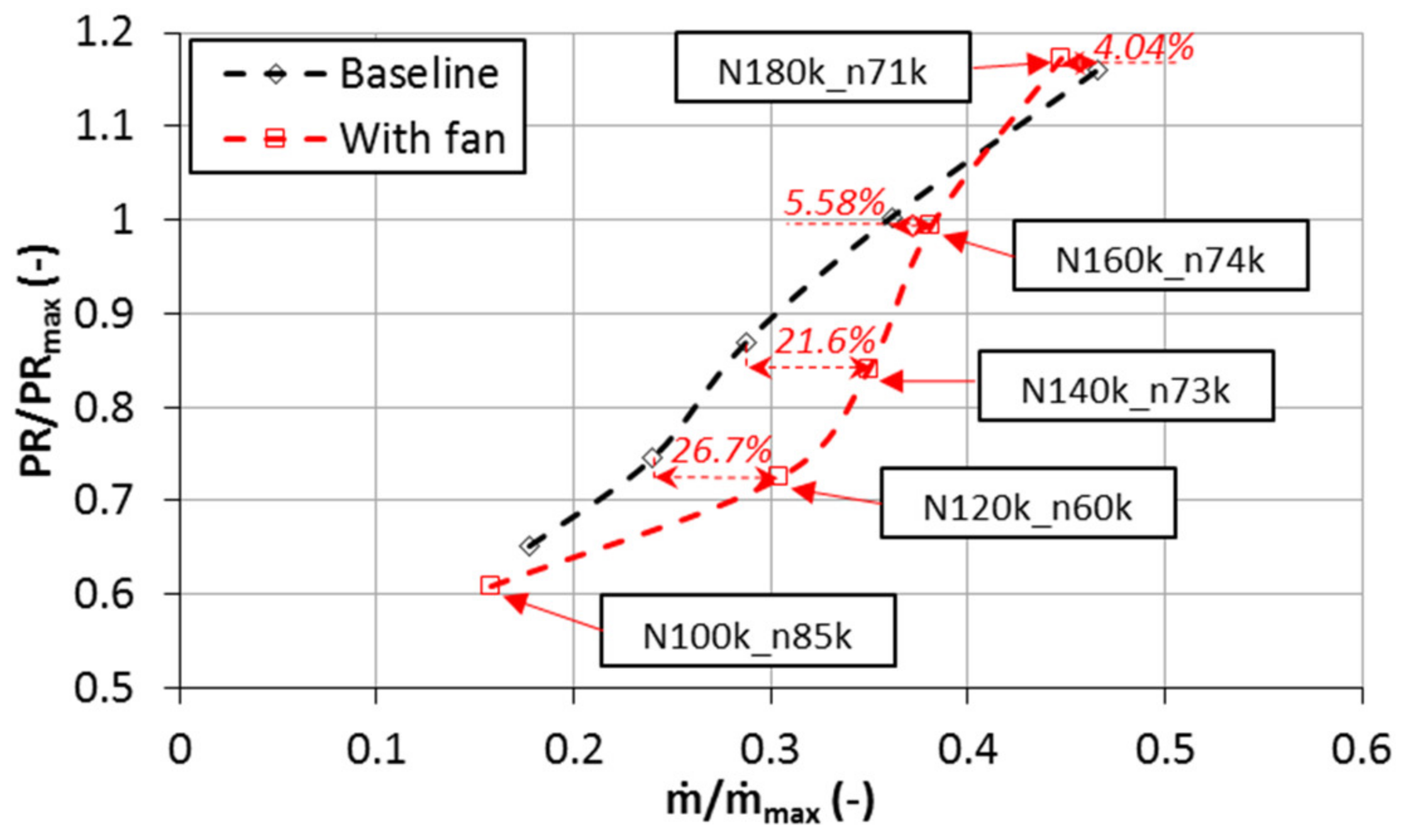
Figure 2 were covered. While the rationale for choosing the fan-operating points within the existing stable operating range of the compressor stage centered on maximizing the fan efficiency, the target for the range extension tests was to maximize the fan speed to deliver as much swirl as possible to the centrifugal impeller. The resulting comparison between the surge line for the baseline configuration and the fan is presented in
Figure 11.
Upon scrutinizing the results depicted in
Figure 11, it is clear that operation with the fan triggered reduced stability at low mass flow rates almost universally, with the exception being the 100% speedline. While the improvement at 100% speed could be theorized as being related to the fact that as pressure ratio increases, the impeller becomes more receptive to the benefits brought about by inlet swirl (as discussed in the Introduction), it does not explain the reduced stability elsewhere. Unfortunately, referring back to
Figure 2, it is notable that the only point where a benefit was obtained in terms of compressor stability yields no tangible advantage when considering on-engine operation.
Similarly, measured performance at 100 krpm also proved to be somewhat unexpected, whereby an apparent reduction in surge mass flow rate was nullified by the compressor operating at significantly lower pressure ratio and a 9.1%pt efficiency decrement. As a consequence, the reduced surge mass flow rate at 100 krpm cannot reasonably be viewed as a useful stability enhancement in comparison to the baseline case.
Prior to evaluating the alterations to the surge line in greater detail, it was deemed worthwhile to briefly examine the peculiarities associated with the 100 krpm surge point on the basis that the insight extracted could prove useful throughout. Upon viewing the result for this operating point, it was theorized that the substantial efficiency drop could be the result of excessive swirl toward the hub side of the passage, instigating a separation at or close to the impeller leading edge (as previously witnessed by Zheng et al. [
16]). Aside from the swirl generated by the fan, swirl generation close to the hub was intensified by the rotating fan spinner, which from examination of
Figure 8, can be seen to extend to the impeller leading edge. In order to evaluate the viability of this hypothesis, the predictions from the CFD study were once again utilized to evaluate the absolute flow angle (relative to the axial direction) on a plane just upstream of the impeller leading edge, as illustrated in
Figure 12.
The presence of a hub side separation and ensuing region of recirculation is readily apparent in
Figure 12. Unfortunately, this phenomenon was unavoidable because, as was discussed in the “CFD Methodology” section, the extended spinner was necessary to maximize the efficiency at points within the existing stable operating range of the compressor. With the susceptibility of stage performance to excessive hub side swirl identified, it was possible to proceed to experimental validation of this phenomenon and a more in-depth evaluation of the compressor stability for the remainder of the surge line.
5.3. Analysis of Reduced Compressor Stability
In order to gain a better understanding of the reasons behind the reduced compressor surge margin, the first step was to examine the interstage measurements gathered during testing to understand if operation of the fan was appreciably altering the extent of the impeller inlet recirculation region. While the CFD simulations did illustrate a tangible interaction, the experimental results provided an unequivocal means of validation.
With both interstage temperature and pressure measurements available close to the impeller leading edge, it was possible to evaluate the alterations to inlet recirculation extent from the test data. While these data were gathered for all operating points, the 120k_NS-operating condition was chosen as the focal point as it exhibited the largest surge margin decrement. The resulting plots of static pressure and temperature are depicted in
Figure 13.
Examination of
Figure 13 demonstrates how the presence of the fan has a clear influence on both the static pressure and temperature values at the impeller leading edge. It is worth noting that the temperature measurements were gathered at an axial distance 0.57D
1s from the impeller leading edge and an immersion depth of 8.5 mm from the shroud wall, while the pressure values were measured at a distance 0.33D
1s from the impeller leading edge on the shroud wall. In both cases Stn 1 was located 35° clockwise from the volute tongue (when viewed from compressor inlet).
Any measured pressure value above zero on
Figure 13 indicates flow that has had work added to it. For the baseline case, the only possible source is flow recirculated along the shroud which emanated from the centrifugal impeller. The fact that reduced static pressure values were witnessed when operating with the fan dictates a reduction in recirculation extent. The same can be said of the temperature values, with values above ambient (constant for all tests) indicating the presence of inlet recirculation, and operation with the fan clearly diminishing this. This observation is consistent with what was witnessed in CFD, whereby the swirl generated by the fan was also shown to successfully reduce inlet recirculation extent. Consideration of the alterations to inlet recirculation extent in isolation therefore would have led to an expectation of enhanced surge margin, with the previous work of Whitfield and Abdullah [
3] citing a direct correlation between inlet recirculation extent and compressor stability. As the opposite was in fact the case, it became clear that further analysis was required to understand the root cause of the reduced compressor stability that had been witnessed. Interestingly, it is clear from
Figure 13 that operation with the fan yielded no appreciable change to the circumferential uniformity of the flow.
The next line of investigation centered on the simulation of operation of the fan in isolation. It was hypothesized that operating the fan at the high rotational speeds required to generate the necessarily high swirl values for surge margin extension may have pushed the fan into an unstable region of its operating range. While it would have been ideal to evaluate the efficacy of this theory experimentally, the aforementioned impeller inlet recirculation region made it difficult to determine the pressure rise across the fan in isolation, an issue compounded by the part span nature of the design and availability of static pressure measurements at the shroud wall only. Consequently, it was decided to conduct the necessary analysis using CFD. To facilitate comparison, a fan-operating map was created using a computational domain including the fan and inlet section only, hence removing the influence of impeller inlet recirculation from considerations. The computational setup was identical to the configuration depicted in
Figure 5, with the exception of having replaced the frozen rotor interface at MP1 with a mass flow rate boundary condition. The corresponding fan-operating map is presented in
Figure 14.
In order to gain an understanding of the operation of the fan, the fan total pressure ratio values generated from CFD data in
Figure 14 were overlaid with the experimentally measured surge mass flow rate values. Upon inspection of the data, it is readily apparent that the fan operated effectively exclusively on the positive slope of its pressure ratio characteristic at the measured surge points. The exception to this is the 180 krpm point (71 krpm fan speed), which while also being most receptive to the benefits of inlet swirl due to operating at the highest pressure ratio of the points examined, was the only point to exude a benefit in operating range in
Figure 11.
While this finding signifies something of a deficiency in the operation of the fan, it is in truth a difficult issue to rationalize from an operational perspective. If the fan was not operated at high rotational speeds, then there is clearly no possibility of generating the high (>60°) swirl angles known to be required for surge margin extension at the relatively low pressure ratios typical of automotive turbochargers. However, by running at high speed, the fan was ultimately pushed into an unstable regime that acted to destabilize the entire compression system. The fan design, as described in
Section 2.1, was a compromise to attempt to satisfy the key engine-operating points illustrated in
Figure 2. However, despite the measures taken to maximize its operating range, this piece of analysis indicates that the fan was in fact the limiting factor.
6. Evaluation of Inlet Duct Losses
At this stage, with potential efficiency benefits having been witnessed at low mass flow rates, the decision was taken to conduct further testing with the fan blades removed (denoted henceforth as the “Unbladed” case). Given the importance apportioned to realizing improvements in system efficiency at low mass flow rates, the primary intention behind testing this configuration was to facilitate gaining an understanding of whether a configuration utilizing a smaller diameter motor could yield a feasible system. By removing the influence of the blades, but maintaining the same meridional flow profile, it was possible to evaluate the proportion of losses attributable to be inlet geometry (S-duct), and hence to provide a more representative baseline for understanding the fan performance. In effect therefore, the test results from this configuration provided information on the inlet geometry-derived performance deficit the fan had to overcome to even match the baseline case.
To complement the analysis that could be undertaken with the “Unbladed” case, a further set of tests were conducted with yet another configuration. Denoted as the “Motor_no_fan” case, this configuration involved installing the motor in the inlet duct without either the fan or spinner assembled onto the shaft. Both additional configurations are depicted in
Figure 15 to clarify the different system layouts.
The intention behind the “Motor_no_fan” case was to understand if the importance apportioned to the extended spinner by the earlier CFD study was reasonable. This is a key consideration here, as while the CFD illustrated that removal of the extended spinner was met with an efficiency penalty of up to 4%pts toward the design point, the added complexity of the rotating assembly brought about by its inclusion, as well as the potential to adversely impact the stability of the stage through introducing hub side separations at low mass flow rates, necessitated further validation to justify its inclusion.
Furthermore, in order to be able to gain further confidence in the assertion that operation of the fan on the positive slope of its operating characteristic was the predominant reason for reduced surge margin, the decision was taken to conduct a further rotating test with this “Unbladed” configuration. By removing the fan blades and testing with the same motor speed, it was possible to evaluate if the supposed separation at the impeller leading edge (as depicted in
Figure 12) caused by the rotating hub wall (spinner) was having an influence on stage stability, without having the associated problems with operating on the positive slope of the fan pressure rise characteristic. A further benefit from the approach was the ability to understand if the CFD predicted efficiency decrement associated with a hub side separation (and that predicted by Zheng et al. [
16]) was plausible.
6.1. Results—“Unbladed” Fan
In keeping with the intended priority of evaluating the performance decrement attributable to the “S-duct,”
Figure 16 presents a comparison between the experimentally measured efficiency and pressure ratio data for the baseline and stationary “Unbladed” cases, normalized against the baseline, for the six operating points of interest.
Inspection of
Figure 16 illustrates something of an unsurprising trend, in that the performance decrement associated with the presence of the electric motor in the flow path becomes more pronounced as mass flow rate increases. With pressure ratio and efficiency decrements in excess of 3% for all but the near-surge points (and exceeding 25% for the highest mass flow rate operating point), it is clear to see that the relatively large motor diameter and resulting “S-duct” inlet geometry brought about performance decrements that were impossible for the fan to overcome.
These results can be rationalized through consideration of the flow obstruction caused by the motor and resulting S-duct; at low mass flow rates the correspondingly low axial velocity flow was not appreciably impacted. As mass flow rates increased however, the increasing axial velocity values in the S-duct brought about not only pressure ratio and efficiency decrements, but also reductions in choke flow capacity for both speed lines (equating to 6.4% for the 120k_NC point). As was discussed previously, while the natural reaction to these results would be to increase the fan speed to attempt to offset some of the losses in the S-duct, this was not possible for the higher mass flow-operating points either due to mechanical limitations or the intolerance of the centrifugal stage to the associated generation of additional swirl.
With the above in mind, what the “Unbladed” configuration does achieve however, is the definition of a more realistic baseline to evaluate the operation of the fan (and hence the potential for the system to perform successfully with a smaller diameter electric motor). Consequently, with this aim in mind,
Figure 17 presents the test results for the fan operating at the rotational speeds defined from the CFD study, as well as the results for the “Motor_no_fan” configuration (with the results in each case presented relative to the “Unbladed” configuration). It is worth noting again that the absence of data at 160k_NC for the case with the axial fan was due to issues with a potential fan over speed situation, so data was not logged for this operating condition. Similarly, the fan-operating condition used in each case was chosen as the one which maximized the overall system efficiency. This dictates that operating conditions are identical to
Table 2 for all but the 160k_NS-operating point, where it was found during the test campaign that the optimum fan speed was 75 krpm rather than the 60 krpm predicted by the CFD study.
Upon examining
Figure 17, it is clear that the axial fan was indeed beneficial in improving performance for both the near-surge-operating points in terms of pressure ratio and efficiency, with the highlight being a 2.47%pt increase in efficiency at the 120k_NS-operating point (which actually exceeded what was predicted from the CFD results presented in
Figure 7). An additional point not captured in
Figure 17 is the impact of the inclusion of the fan on the turbine power requirement for a given compressor-operating point. As was discussed in the Introduction, the potential of the addition of positive pre-swirl to “unload” the compressor and hence improve turbocharger transient response was cited as a benefit of this system. While the experimental setup employed did not make it possible to conduct transient tests, it was possible to infer potential reductions in engine time-to-torque figures through examining the measured turbine power values (calculated using turbine mass flow rate and total temperature drop) with and without the fan. As the engine full load line tracks close to the compressor surge line (as depicted in
Figure 2), data to characterize this phenomenon are presented exclusively for the two near-surge points in
Table 3. Furthermore, measured improvements in compressor efficiency have already been cited at these points and explained as being the primary objective of the study. The data presented in
Table 3 are supplemented with the corresponding alterations to compressor pressure ratio and efficiency, and like in
Figure 17, the data in each case are presented as a change relative to the results from the “Unbladed” fan configuration.
The results depicted in
Table 3 highlight that for both near-surge points, the efficiency improvements have been realized in conjunction with appreciable reductions in turbine power requirement. These reductions in the measured values of turbine power when operating with the fan correlate to improved turbocharger transient response, as the additional turbine power available can be used to help accelerate the turbocharger rotating assembly. It is also readily apparent that with turbine power values of 4.4 kW and 10.8 kW for the “Unbladed” configuration at the 120k_NS and 160k_NS points respectively, the benefits brought about by the fan have been achieved while reducing the overall energy consumption of the system. Furthermore, the modest fan power values highlighted in
Table 3 would be capable of being supplied without requiring significant adaptations to the existing vehicle electrical system.
Returning to
Figure 17, unfortunately the measured performance at the higher mass flow-operating conditions did not exude the same benefits as their near-surge counterparts. In each case, inclusion of the fan was in fact detrimental in comparison to the “Unbladed” case. In spite of the concessions made to maximize choke side performance through utilizing a part span design, large pressure ratio and efficiency decrements are in evidence. As was mentioned during the discussion of the CFD results however, this was something of an unavoidable scenario, as increasing fan speed to overcome pressure loss across the fan brought about even more substantial reductions to system performance due to the intolerance of the centrifugal stage to positive pre-swirl at higher mass flow-operating conditions. It is also worth noting that aside from the performance penalty, a reduction in choke flow capacity resulted in the 120k_NC operating point having to be logged at a 3.5% lower mass flow rate for the case with the fan in comparison to the “Unbladed” case. This mass flow disparity explains why
Figure 17 illustrates an apparently greater efficiency decrement for 120k_DP than 120k_NC. However, having examined the significant handicap provided by the relatively large motor diameter as presented in
Figure 16, considering the preceding discussion relating to fan performance in isolation, it would not be unreasonable to consider that use of a smaller diameter electric motor could potentially result in a feasible system.
Moving on to consideration of the influence of the extended spinner, it is pertinent to first of all scrutinize the data generated from the “Motor_no_fan” configuration. It is clear from
Figure 17 that the results from the CFD study indicating the importance of the inclusion of the extended spinner were correct. For all operating points except the 120k_NS condition, removal of the fan and spinner brought about an efficiency decrement. In particular, the previously quoted drop in efficiency from the CFD study of 4%pts at 160k_DP was similar to the 3.2%pts witnessed in the test data. Clearly therefore, in spite of the added complexity of including the extended spinner in the design, it was necessary to maximize the system performance.
In order to evaluate the potential contribution of the extended spinner in instigating the onset of a swirl induced separation close to the impeller leading edge, and consequently causing the reduction in compressor operation range witnessed in
Figure 11, tests were conducted with the “Unbladed” fan rotating at the same speed as that defined previously. It is notable that only the measured 120 krpm surge point was evaluated for this configuration; this decision was taken in recognition of the fact that it was the most important operating point for this analysis. Being the operating point of minimum mass flow rate, it consequently was most susceptible to the influence of the swirl generated by rotating spinner due to having the smallest axial velocity values in the inlet region.
Upon comparing the result with the corresponding operating point for the baseline case, two conclusions became abundantly apparent. First, the previously discussed theories relating to bringing about separation at the impeller leading edge appeared correct. In the same vein as what was witnessed by Zheng et al. [
16] and was discussed surrounding
Figure 12, the presence of the rotating spinner brought about an appreciable efficiency decrement of 2.2%pts. While no direct validation of the mechanism at play was possible, the evidence gathered during testing correlates with the CFD-based findings, which highlighted a swirl-based hub side separation close to the impeller leading edge as the cause. Second, operation with the rotating spinner had no impact on the experimentally measured surge margin. This finding illustrates that while the separation influenced the measured compressor efficiency, it was not a governing aspect of the reduced stability witnessed when operating with the fan. As a consequence, these findings further validate that operation on the positive slope region of the fan pressure characteristic was indeed the predominant issue.
7. Conclusions
An integrated active inlet pre-swirl generation device concept was successfully progressed through design, manufacture, and experimental testing phases. 1-D, 3-D CFD, and FEA analyses were used to develop a functional prototype utilizing off-the-shelf electrical components and hardware manufactured in QUB. The prototype system successfully completed the test campaign and performed in line with what was required following the initial CFD study. Regarding the CFD methodology, the approach employed was ultimately shown to result in an adequate design tool, with the overall trends having been well represented, but ultimately more pronounced in the test data.
Inclusion of the axial fan brought about both stage efficiency and pressure ratio benefits for the near-surge-operating conditions, typified by a 3.0%pt increase in efficiency for the 120k_NS operating point in comparison to the baseline configuration. Similarly, corresponding measured reductions in turbine power for both near-surge-operating points provided evidence of transient response benefits that would ultimately be very helpful during on-engine operation.
However, similarly to what was predicted in the CFD study, the fan was not capable of achieving the desired performance/neutral influence at the higher mass flow rate-operating points. This was largely the result of the constraints on inlet geometry imposed by the relatively large diameter electric motor, with the resulting total pressure losses being incapable of being overcome by the action of the fan. The natural inclination to increase fan speed to help offset the increasing total pressure drop in the inlet section as mass flow rate increased was curtailed either by mechanical considerations for the motor/fan, or through the intolerance of the centrifugal stage to the additional swirl generated (manifesting itself through further reductions in efficiency and choke flow capacity).
Similarly, while the potential to generate high swirl angles with the fan was demonstrated, these did not translate into improvements in surge margin for the compressor stage. The high pre-swirl angles required to bring about benefits in the relatively low pressure ratio compressor typical of automotive turbochargers, combined with the design compromises required to enable a wide range of operation, resulted in a fan that was aerodynamically unstable at the required high rotational speed, low flow conditions. This instability ultimately triggered the onset of surge at higher mass flow rates than were witnessed for the baseline configuration.
In terms of an outlook, there is little doubt that a smaller diameter, faster rotating electric motor could significantly negate the performance decrements witnessed in this study at the higher mass flow rate operating conditions. Coupling removal of the requirement for the S-duct inlet geometry with a higher speed motor would be highly beneficial in improving the choke side performance and would also open up additional design freedom to overcome the surge margin issues. However, specification of such a motor, suitable control electronics and the fan itself may yield a system that is too expensive to be feasible for a product destined for series production. Furthermore, combining such a system with a specific design/selection of base compressor stage to work with inlet swirl would be worthy of investigation. The issue is that automotive turbocharger compressors already target a wide operating range. Consequently, it may be more beneficial to design the base compressor stage for a reduced surge margin (as a byproduct of targeting improvements in peak efficiency), then recover stability at low mass flows through coupling with a technology such as this. Use of a bespoke base compressor stage (rather than the off-the-shelf unit utilized herein) would also facilitate other complementary geometry changes, such as an increased inducer hub diameter, which would further negate the need for the aforementioned S-duct inlet geometry. Regardless, it is clear that the inducer must be the critical component for stability to reap operating range benefits through the application of pre-swirl (due to the relative insensitivity of impeller outlet flow to the effects of pre-swirl) [
17].
Author Contributions
Conceptualization, A.S. and C.S.; methodology, C.S.; software, C.S. and S.T.; validation, C.S.; formal analysis, C.S. and S.T.; investigation, C.S. and S.T.; resources, S.S. and A.S.; writing—original draft preparation, C.S.; writing—review and editing, S.S.; supervision, S.S. and A.S.; project administration, C.S.; funding acquisition, A.S. All authors have read and agreed to the published version of the manuscript.
Funding
This research received no external funding.
Acknowledgments
The authors would like to sincerely thank IHI Charging Systems International GmbH for provision of the necessary compressor hardware for testing, as well as for their continuing technical support. The authors would also like to extend their thanks to ANSYS Inc. for the use of their CFD software and their technical support during this program of research.
Conflicts of Interest
The authors declare no conflict of interest.
Abbreviations
| D | Diameter (m) |
| i | Incidence (°) |
| n | Electric motor speed (rpm) |
| N | Turbocharger shaft speed (rpm) |
| ṁ | Mass flow rate (kg/s) |
| p | Static pressure (Pa) |
| p0 | Total pressure (Pa) |
| P | Power (W) |
| PR | Total pressure ratio (-) |
| T | Temperature (K) |
| T0 | Total temperature (K) |
| U | Blade speed (m/s) |
| V | Absolute velocity (m/s) |
| W | Relative velocity (m/s) |
| ΔW | Specific work (J/kg) |
| Z | Blade number (-) |
| α | Absolute flow angle measured from meridional (°) |
| β | Relative flow angle measured from meridional (°) |
| γ | Ratio of specific heats (-) |
| η | Isentropic total-total efficiency (-) |
| BLDC | Brushless Direct Current |
| DP | Design point |
| FEA | Finite Element Analysis |
| MP | Measurement Plane |
| NC | Near choke |
| NS | Near surge |
| QUB | Queen’s University Belfast |
| SFM | Swirl flow meter |
| Subscripts: | |
| a | Axial direction |
| A | Fan leading edge |
| b | Blade |
| B | Fan trailing edge |
| c | Compressor |
| corr | Corrected |
| fan | Axial fan |
| h | Hub location |
| s | Shroud location |
| turb | Turbine |
| u | Tangential direction |
| 0 | Stagnation/total conditions |
| 1 | Impeller inlet |
| 2 | Impeller exit/vaneless diffuser inlet |
| 3 | Vaneless diffuser exit |
| max | Maximum value for a given parameter |
References
- Stuart, C.; Spence, S.W.; Teichel, S.; Starke, A. Design and Evaluation of an Active Inlet Swirl Control Device for Automotive Turbocharger Compressors. In Proceedings of the 14th International Conference on Turbochargers and Turbocharging, London, UK, 11–12 May 2021; CRC Press/Balkema: London, UK, 2021; pp. 1–14. [Google Scholar]
- Ishino, M.; Iwakiri, Y.; Bessho, A.; Uchida, H. Effects of variable inlet guide vanes on small centrifugal compressor performance. In Proceedings of the Volume 3: Heat Transfer, Electric Power, Industrial and Cogeneration, ASME International, Indianapolis, IN, USA, 7–10 June 1999; pp. 99–157. [Google Scholar]
- Whitfield, A.F.; Abdullah, A.H. The Performance of a Centrifugal Compressor with High Inlet Prewhirl. In Proceedings of the Volume 1: Aircraft Engine, Marine, Turbomachinery, Microturbines and Small Turbomachiner, New Orleans, LO, USA, 4–7 June 2001; Volume 102, pp. 487–493. [Google Scholar] [CrossRef]
- Fraser, N.; Fleischer, T.; Thornton, J.; Rueckauf, J. Development of a fully variable compressor map enhancer for automotive application. SAE Tech. Pap. Ser. 2007, 116. [Google Scholar] [CrossRef]
- Lüdtke, K.H. Process Centrifugal Compressors: Basics, Function, Operation, Design, Application; Springer: Berlin, Germany, 2004. [Google Scholar]
- Kleine Sextro, T.; Steglich, T.; Seume, J.R. Variable Inlet Guide Vane Device for a Turbocharger Compressor. In Proceedings of the International Gas Turbine Congress, Tokyo, Japan, 17–22 November 2019. [Google Scholar]
- Harley, P.; Spence, S.; Filsinger, D.; Dietrich, M.; Early, J. Meanline modeling of inlet recirculation in automotive turbocharger centrifugal compressors. J. Turbomach. 2014, 137, 011007. [Google Scholar] [CrossRef]
- Stuart, C.; Spence, S.; Filsinger, D.; Stärke, A.; Kim, S.I. Characterising the influence of impeller exit recirculation on centrifugal compressor work input. In Proceedings of the Volume 2A: Turbomachinery, Charlotte, NC, USA, 26–30 June 2017; Volume 140. [Google Scholar] [CrossRef]
- Li, X.; Spence, S.; Wu, Y. The interaction between inlet guide vanes and the impeller recirculating flow in a centrifugal compressor and the resulting impact on flow range. In Proceedings of the Volume 2B: Turbomachinery, Oslo, Norway, 11–15 June 2018; pp. 2018–75097. [Google Scholar] [CrossRef]
- Fledersbacher, P.; Löffler, P.; Sumser, S.; Wirbeleit, F. Exhaust Gas Turbocharger for an Internal Combustion Engine and a Method for Operating an Exhaust Gas Turbocharger. USA Patent No. US6481205B2, 19 November 2002. [Google Scholar]
- International Organisation for Standardization. ISO 1940-1:2003(E) Mechanical Vibration—Balance Quality Requirements for Rotors in a Constant (Rigid) State–Part 1: Specification and Verification of Balance Tolerances; ISO: Geneva, Switzerland, 2003. [Google Scholar]
- ABB Process Automation, 2011, “FS4000 Swirl Flowmeter,” D184S035U02. Available online: https://library.e.abb.com/public/0aa843f6bd0f8c3fc1257950003d95d0/D184S035U02-EN-12-11_2011.pdf (accessed on 19 January 2021).
- Micro-Epsilon Messtechnik. “Operating Instructions turboSPEED DZ140,” X9751314-A071069HDR. 2016. Available online: https://www.micro-epsilon.co.uk/download/manuals/man--turboSPEED-DZ140--en.pdf (accessed on 21 January 2021).
- GE Sensing, Druck PMP 4000 Series Specifications, General Electric. 2007. Available online: https://cdn.shopify.com/s/files/1/0797/9339/files/pmp4000.pdf?11902880808471937698 (accessed on 21 January 2021).
- British Standards Institution. BS1904: Specification for Industrial Platinum Resistance Thermometer Sensors; BSI: London, UK, 1984. [Google Scholar]
- Zheng, X.; Huang, Q.; Liu, A. Loss mechanisms and flow control for improved efficiency of a centrifugal compressor at high inlet prewhirl. J. Turbomach. 2016, 138, 101011. [Google Scholar] [CrossRef]
- Harada, H. Study of a Surge-Free Centrifugal Compressor with Automatically Variable Inlet and Diffuser Vanes. In Proceedings of the Volume 1: Turbomachinery, ASME 1996 International Gas Turbine and Aeroengine Congress and Exhibition, Birmingham, UK, 10–13 June 1996. [Google Scholar] [CrossRef]
| Publisher’s Note: MDPI stays neutral with regard to jurisdictional claims in published maps and institutional affiliations. |
© 2021 by the authors. Licensee MDPI, Basel, Switzerland. This article is an open access article distributed under the terms and conditions of the Creative Commons Attribution (CC BY) license (https://creativecommons.org/licenses/by/4.0/).


