Review

The Possibility of a High-Efficiency Wave Power Generation System Using Dielectric Elastomers

1
Chiba Science Institute, Yagumo, Meguro Ward, Tokyo 152-0023, Japan
2
Wits Inc., Oshiage, Sakura, Tochigi 329-1334, Japan
3
Institute of Ship Technology, Ocean Engineering and Transport Systems, University of Duisburg-Essen, 47057 Duisburg, Germany
4
Zeon Corporation, Shin Marunouchi Bldg, Chiyoda Ward, Tokyo 100-8246, Japan
5
Fukuoka Institute of Technology, Wajirohigashi, Higashi Ward, Fukuoka 811-0295, Japan
*
Author to whom correspondence should be addressed.
Energies 2021, 14(12), 3414; https://doi.org/10.3390/en14123414
Submission received: 24 April 2021 / Revised: 1 June 2021 / Accepted: 4 June 2021 / Published: 9 June 2021
(This article belongs to the Special Issue The Advances in Wave Energy Extraction Systems)

Abstract

:
Power generation using dielectric elastomer (DE) artificial muscle is attracting attention because of its light weight, low cost, and high-efficiency. Since this method is a system that produces electricity without emitting carbon dioxide nor using rare earths, it would contribute to the goal of environmental sustainability. In this paper, the background of DEs, the associated high efficiency wave energy generation (WEG) systems that we developed using DEs, as well as the latest development of its material are summarized. By covering both the challenges and achievements, this paper discusses the opportunities to build the foundation of an energy recycling society through the usage of these WEGs. To make these possibilities commercially successful, the advantages of DEs need to be integrated with traditional technologies. To achieve this, the method of using DEs alone and a system used in combination with an oscillating water column were also considered. Finally, the current status and future of DE generators (DEGs) are discussed.

1. Introduction

Most commercial power generation systems use electromagnetic induction in which the generator is rotated by mechanical energy. Electricity is, for example, generated by a turbine (utilization of mechanical energy) driven by wind, water falling from a high place, or a flow from a stream. Small-scale power generation using renewable energy is currently becoming widely used due to problems such as environmental pollution, including issues related to global warming and population explosion [1,2,3]. However, traditional generators that use electromagnetic induction tend to operate most efficiently at high frequencies in a narrow range, which may make them unsuitable for renewable energy sources [4]. Sources for utilizing renewable energy generate motion over a wide range of low frequencies, so power generation systems that use electromagnetic induction must include mechanical or hydraulic transmissions, making the system more complex. Consequently, it will be expensive.
A DE (dielectric elastomer) is one of the most promising artificial muscles and is also a new transducer technology that can convert mechanical energy into electrical energy. Compared to conventional generators that use electromagnetic induction or piezoelectric effects, generators that use DEs have been found to generate electricity more efficiently, with higher energy densities, and at lower frequencies [5,6,7].
In this paper, some high-efficiency wave energy generation (WEG) systems that have been developed using DEs are summarized and the opportunity to build the foundation of an energy recycling society using these DE generators (DEGs) is considered. One way to make these opportunities commercially successful is to incorporate DEs into traditional technology and take advantage of DEs’ strength. In this paper, the method of using DEs alone and a system of combined use with oscillating water column wave energy converters (OWCs) are considered. The current status and future of DE generators are also discussed.

2. Background of Dielectric Elastomers

A DE is a transducer technology invented by Pelrine and Chiba at SRI International (Stanford Research Institute USA) in early 1991 [8]. As shown in Figure 1, the basic element of a DE is a very simple structure consisting of a thin polymer film (elastomer) sandwiched between two electrodes. When a voltage difference is applied between the electrodes, the electrodes are attracted to each other by electrostatic force (Coulomb force), and the elastomer contracts in the thickness direction and expands in the plane direction.
A DE can achieve a very efficient conversion of electrical energy to mechanical energy [9]. The energy density of a DE reaches 3.4 J/g, which is about 21 times that of single crystal piezoelectric elements and more than two orders of magnitude higher than most commercially available actuators [9,10]. As shown in Figure 2, a 0.15 g DE can lift an 8 kg weight by 1 mm or more at a speed of 88 mc with our latest design [11]. However, the edge of the DE was reinforced so that it would not be destroyed by repeated loads, and the total weight was set to 0.97 g. Also, for deformation, as shown in Figure 3, it has reached 680% so far [12]. The polymer used for them was acrylic #a (see Table 1), and the electrode material was a single-walled nanotube (ZEONANO®-SG101, Zeon corp., Tokyo, Japan.
It has been observed that when the above operation is reversed, power is generated, for example, when the DE is pulled by an external force or when pressure is applied by an external force [10].
Currently, there are two approaches: (1) DE materials and mechanical systems using DEs [6,9,10,11,12,13,14,15,16,17,18,19,20,21,22,23,24,25,26,27,28,29,30,31,32,33,34,35], and (2) operational strategies (circuit design) [36,37,38,39] that are being studied.
The following are relevant papers on DE materials and mechanical systems using DEs:
Chiba et al. made DEs from silicon and acrylic, and discovered that acrylic has greater elongation and actuation pressure [6]. Chiba et al. have also shown the effectiveness of carbon nanotubes as an electrode for DEs [11]. Koh et al. showed that various models of failure, including electrical breakdown, electromechanical instability, loss of tension, and rupture by stretching defined a cycle of maximal energy of conversion [13]. Jean-Mistral et al. presented a DEG that could obtain very small amounts of energy from human motion [15]. Huang et al. claimed that they achieved significant improvements in energy density and power density using equi-biaxial stretching [21]. Vertechy et al. showed a reduced, dynamic model for an inflated circular diaphragm dielectric elastomer generators that features one kinematic degree of freedom and which accounts for DE visco-elasticity [24]. The performance of a DEG composed of an annular membrane deformed out-of-plane by an external oscillating loading was investigated employing a hyper-electro-elastic model with parameters adjusted to simulate the behavior of material such as an acrylic elastomer and a type of natural rubber [25]. Moretti et al. investigated parallelogram-shaped dielectric elastomers and they claimed that those were effectively employed as both rotary and linear transducers [26].

3. Dielectric Elastomer Generators (DEGs)

As mentioned above, the operating principle in generator mode is the conversion of mechanical energy to electrical energy by the deformation of a DE. Functionally, this mode resembles piezoelectricity, but its power generation mechanism is fundamentally different. With DEs, electric power can be generated even by a slow change in the shape of the DE [10], while for piezoelectric devices impulsive mechanical forces are needed to generate the electric power [5,7,10]. Also, the amount of electrical energy generated and the conversion efficiency from mechanical to electrical energy can be greater than that from piezoelectricity [5,7,10,30,39]. Figure 4 shows the operating principal of DE power generation.
Figure 5 shows a schematic diagram of the power generation cycle. The power generation phenomenon of a DE is considered to occur through the following four steps [10]:
(1)
When mechanical energy is applied to the DE film and the film is stretched, the thickness of the film decreases and the surface area increases at the same time;
(2)
At this time, a voltage is applied to the film. The added electrical energy is stored in the membrane as an electric charge;
(3)
When the mechanical energy of the membrane decreases, the elastic resilience of the membrane acts to restore the original thickness and reduce the area. At this time, the electric charge is pushed out toward the electrode. This change in the position of the charge increases the voltage difference and results in an increase in electrostatic energy;
(4)
The charge is removed from the membrane and the membrane returns to its original length.
In each expansion and contraction cycle shown above, the energy E produced by the DE is associated with the change in the capacitance of the DE, and that energy E can be expressed by the following equation [10]:
E = 0.5C1Vb2(C1/C2 − 1)
Here, C1 and C2 are the DE capacitances in the expanded and contracted states, respectively, and Vb2 is the bias voltage. This power generation theory was proved by Chiba et al. in a power generation experiment using a two-dimensional tank in 2013 [35]. Considering the change in voltage, the charge Q of the DE can be regarded as constant in a basic short circuit. Also, since V = Q/C, if the contraction voltage is V2 and the expansion voltage is V1, it can be expressed as follows:
V2 = Q/C2 = (C1/C2)(Q/C1) = (C1/C2)V1
Based on the above energy theory, the contraction voltage is higher than the extension voltage because C2 < C1. That is, power generation occurs. Where the capacitance C of the DE film can be expressed as:
C = ε0εA/t = ε0εb/t2
ε0 is the permittivity of free space, ε is the permittivity of the dielectric elastomer film, A is the moving area of the elastomer film, t is the thickness, and b is the volume of the film. In Equation (3), the volume of the elastomer basically does not change, so A/t = b = is constant.
The power (E) actually obtained by a DEG can be calculated by the following procedure using each of the above equations above.
(1)
The voltage (V2) between the electrodes on both sides of the DEG in the contracted state can be measured for each wave frequency using a digital oscilloscope (see Figure 6).
(2)
The capacitance (C2) of the transducer in the contracted state is measured with a digital multimeter (see Figure 7).
(3)
Using the values of Equations (1) and (2), and C2 and V2, the amount of power generation is calculated as follows:
(a)
The relationship C1 = V2C2/V1 is derived from Equation (1).
(b)
Next, by introducing C1 into Equation (2), the generated electric power can be obtained:
E = 0.5V1V2C2(V2/V1 − 1)
(c)
Using Equation (4) and the values of C2 and V2, the power generated at the frequency of each wave of the transducer can be calculated
It should be noted here that if the amount of power generation is not calculated according to the above procedure, the energy applied at the initial stage will be included in the calculation, resulting in an erroneous result [31]. There have been several cases of papers calculating the power generation not following the correct procedure recently, but it is not possible to determine the correct amount of power generation unless the added energy and the generated energy are clearly separated.
Figure 8 summarizes the sites where the DEGs can be installed and shows each conceptual diagram of the generation systems [40]. They are (a) wind power generators on the roofs of buildings, (b) water mill generators, (c) waste energy generators, (d) drain generators, (e) road power generation system using a DE sheet, (f) wind power generators, (g) solar heat generators, (h) wave generators near the shore, (i) water flow generators, (j) wave generators in the ocean, (k) hydrogen production plant, (l) a tanker carrying hydrogen, and (m) road power generation.
Except for (k) and (l), they are specifically power generation limited to local consumption. In order to achieve zero carbon dioxide emissions in 2050 [3], large-scale offshore wave power generation (k) is indispensable, and the best scenario is to convert the power obtained there into hydrogen and transport it to land [41].

3.1. Buoy Power Generation Loaded with Dielectric Elastomer Generator

A DE buoy generator has been developed and was tested for the first time in the world in a tank 1.4 m wide, 1.7 m high (water depth 0.5 m) and 20 m long [9]. Figure 9 shows this DE wave power generation system. This generator showed exciting potential. Using only an about 40 g DE, we generated more than 5 J/stroke at 0.3 Hz. Light-emitting diode (LED) lights for navigation buoys were able to be flashed continuously, using the electricity generated. The DE polymer used in the experiment was acrylic #a (see Table 1), and the electrode was made in carbon black as shown in Table 2 of Section 4.2. “Electrode Material used for Dielectric Elastomers”.
The world’s first buoy power generation experiment using waves in the real sea was conducted in August 2007 in Tampa Bay, Florida, USA [10]. Figure 10 shows a buoy power generator system equipped with DEGs. The DE used in this experiment weighed 150 g [9]. The material of the film used was acrylic #a (see Table 1). The electrode was made in carbon black as shown in Table 2.
The maximum measured electrical output capacity, verified in laboratory tests, was 12J per generator stroke. Unfortunately, the wave height in that area during the experiment was only a few centimeters, and it was very difficult to test the wave power generator. Therefore, there was no choice but to use a motor boat to generate waves with a height of 10 cm. At a bias voltage of 2000 V, a peak energy of 3.6 J at a wave height of 10 cm was able to be generated. In this system, a 62 kg weight was attached to the bottom of the buoy, the weight was raised and lowered by the movement of the waves, and the force was used to expand and contract the DE to generate electricity. However, due to its heavy inertia, small waves did not generate much power. In December 2008, another ocean test was conducted in California, USA, confirming that the generated electrical energy was always stored in the battery [42].
Based on the above results, a method to fix the buoy to the seabed with a mooring wire was developed, so that even small waves could generate electricity. In other words, the DEG was tied to a mooring rope and the other end of the rope was fixed to the seabed, so when a wave hits the buoy, the buoy moved upward on the wave. However, since the DEG was fixed with a rope, the DEG was deformed and power was generated. In 2010, an actual sea trial was conducted along the coast of the Izu Peninsula in Shizuoka Prefecture, Japan using this fixed type [42,43]. The shape of the DEG used in this experiment was a drape type (diameter 260 mm, height 120 mm, weight 4.6 g), the electrode material was carbon black (see Table 2), and the elastomer was acrylic #a (see Table 1). A schematic diagram of the DEG is shown in Figure 11.
The purpose of this experiment was achieved brilliantly by demonstrating that even a small wave equivalent to a wave of several centimeters can generate electricity. However, the system did not have a built-in structure to maintain constant tension as the tide level changed.
To solve the problem above, the power generation system developed in the summer of 2011 was moored on an underwater horizontal plate with some degree of redundancy to accommodate changing tide levels (see Figure 12) [31,42]. This principle focused on the difference in buoyancy between the buoy and the plate. That is, when a wave hits the buoy and the plate, the buoyancy of the buoy is lighter, so the buoy starts to move vertically first and, as a result, the distance between the buoy and the plate becomes longer. Thus, the DEG is deformed, and power generation occurs. By adopting this mooring method, it would be possible to automatically generate electricity for a long time regardless of changes in the tide level. As a result, even if it is deep, it no longer needs to be fixed to the seabed. Even in deep water, power can be generated by mooring it on floating bodies such as super-large ships and super-mega floats floating in the ocean (see Figure 13) [31]. Considering practical applications, cost reduction and the pursuit of convenience are indispensable, and miniaturization of the power generation system is also an important issue. In this wave power generation system, the power generation control circuit can be miniaturized and integrated with the DE power generation unit to eliminate the storage space provided under the buoy. As a result, the size and weight have been reduced by about one-third (see Figure 14).
In the above experiment, not only vertical movement due to DE waves but also horizontal movement due to tidal currents were observed [20]. There were two reasons; (1) it was connected to a longer mooring wire and (2) because the buoy was moved horizontally by the waves. As a result, the mooring wire was tensioned, and the DEG was deformed. Figure 15 shows the movement of the buoy in response to the waves. By combining these two movements well, it is thought that power can be generated more efficiently.

3.2. Usefulness of Dielectric Elastomer Wave Power Generation

Whereas traditional wave generators tend to differ slightly from the optimal natural cycle and significantly reduce power generation efficiency, DE-based generators produce stable power from the short to long term. In 2013, we conducted a basic experiment using a two-dimensional wave power tank and demonstrated for the first time in the world that DEG is an innovative wave power generation system capable of generating power over a wide range of frequencies [35]. A wave tank with a length of 30 m, width of 0.6 m and a depth of 1.5 m was used, as shown in Figure 16. The water depth was 0.6 m. The film used for the DE was acrylic #a (see Table 1). The electrode was made from carbon black as shown in Table 2. The floating body used for the experiment was made of urethane foam with a size of 59 cm × 30 cm × 10 cm. This experiment showed that a DE generator can stably output about 70% of electrical energy on average from short to long cycles (see Figure 17) [35]. This value is the power generated from the DE divided by the wave divided by the maximum output value measured in the laboratory multiplied by 100.
Anomalies occurred at the wave periods of 1.2 to 1.4 Hz. This was because the waves in the water tank passed through the floating body with the DE attached, hit the wall of the water tank on the opposite side, and bounced off, generating interference waves to generate electricity. It seems that the value temporarily increased or decreased.
Moretti [19,26,27], Vertechy [24] et al. also experimented with incorporating DEGs into an oscillating water column wave energy converter, demonstrating the importance of DE power generation.

3.2.1. Buoy–Buoy Interaction

In order to build a super megawatt power generation system using buoys, it is necessary to arrange many buoys as shown in Figure 13. Therefore, we need to know what happens in the interaction between buoys. First, in a two-dimensional water tank, three-buoys were lined up in a row in the same direction as the waves traveled, and tested to observe how the waves interfered with them (see Figure 18) [44]. The test tank used for the experiment had a total length of 15 m, a width of 1 m, and a water depth of 1.4 m, and the experimental float was moored near the center. A rectangular parallelepiped urethane (990 mm × 250 mm × 80 mm) was used as a floating body, which was fitted with points for observing movement. The floating motion was measured by tracking the points with a CCD camera and measuring the amount of movement. The floating body moves with three degrees of freedom in heave, surge and pitch by guides set at the four corners for restricting the motion. The mooring wire is connected to the ring gauge via a pulley installed below the floating body, making it possible to measure the tension acting on the mooring wire. In addition, a wave height meter (needle-type servo wave height meter) was installed between the floating body, the wave generator, and the wave-dissipating plate to measure the height of the waves entering the floating body and the waves passing through the floating body.
In the range where the wave period is smaller than about 0.6 s, most of the wave is deflected by the collision with the first floating body. As a result, it does not reach the floating body behind it and the influence on the multiple floating bodies becomes very small. When the wave period is around 0.8 s, the influence of multiple floating bodies becomes large, and an increase in surge and pitch, and a decrease in mooring tension are particularly noticeable with the floating body which first collides with the wave. At that time, although the influence of the spacing of the floating bodies at different intervals is small, the influence becomes large as the number of floating bodies increases. For a wave period of around 1.0 s, it was revealed that if the interval of the floating bodies is narrow, the surge and the pitch of the floating body which first collides with the wave increases. Therefore, if the interval is wide, it would increase the mooring tension.
The above experimental data were numerically modeled, simulated and compared with the physical wave tank test [45]. The conditions analyzed are a single body A, double bodies (A and B) at different intervals, and a case with triple bodies (A, B and C). It was assumed that the bodies were arranged in the order of A, B and C. Results found in this simulation are summarized below:
(1)
The calculated motion (surge, heave, pitch), mooring tension, and power generation efficiency were in good agreement with the experimental measurements.
(2)
In the case where double bodies are placed next to each other: when the wave frequency is high, the associated response amplitude operators (RAO) of surge, heave, and tension are small, but the RAO of pitch motion is large. That is, the RAO of body B is smaller than the RAO of body A, and it can be seen that the movement and mooring tension of body B are weakened by the presence of the body A. Due to the presence of the body, the wave is diffracted and a part of the wave energy is converted to electrical energy using the power-take-off system.
(3)
The efficiency of floating body A reduces at the low wave frequencies, but increases at high wave frequencies when the interval is increased from 0.5 m to 1 m from the case above. On the other hand, there was no significant difference in the efficiency of floating body B. It seems that the effects of the diffracted waves from body B on body A are more pronounced than the other way around. Apart from the reason that the floating body A with a DE extracts some of the wave energy, the results might show differences within the results of a 3D experimental work or high-fidelity simulations.
(4)
The power generation efficiency was calculated for the wave frequency in the case where the triple bodies were arranged side by side. In general, the power generation efficiency of the first body (A) that encounters the incident waves first is largest; the associated efficiency of the second body (B) is somewhat less than that of the first body, and so on. This can also be interpreted as the DE attached to the floating body absorbing part of the wave energy. In a particular wave frequency range, all wave energy converters (OWSs) can reach relatively high efficiencies; about 0.9 Hz for this studied case. The reason for this is that lower wave frequencies naturally reduce buoy-to-buoy interaction.

3.2.2. System That Incorporates a Dielectric Elastomer into Oscillating Water Column Wave Energy Converter Buoys Is Arranged

OWCs are one of the most promising wave energy transducers [46]. The efficiency of an OWC device peaks at the resonated wave period [46]. However, the efficiency decreases significantly at other wave periods. There are two possible ways to increase the power generation efficiency of the OWS:
(1)
By arranging the DEG around the OWC, it is possible to handle waves with a period that OWSs are not good at. This is because, as discussed above, the wave period in which the DEGs can generate is very wide.
(2)
A DEG is placed in place of the compressor and electromagnetic motor used in the OWC, and the air compressed by the waves deforms the DE to generate electricity: using this idea, some testing has been done by incorporating DEGs into OWCs [24,27,32].
Idea 2 above has promise, but there might be some problem with the DE used. From Equations (1) and (3) discussed above, the points are the thickness of the DE and the magnitude of the voltage applied to it. Looking at the experimental cases, the voltage applied is too small, around 1000 V, even though the film thickness is rather thick. Therefore, even if a low voltage is applied while the film is not sufficiently deformed, power generation might be unlikely to occur.
In order to realize super mega power generation using larger waves, a power generation system with many buoy-type OWCs was proposed [31]. This method does not use a copper or electromagnetic motor, which is expensive. In addition, due to the high generation efficiency, the power generation cost is expected to be around 5 US cents/kW [41]. This is almost the same as thermal power generation using heavy oil or coal. Currently, as the first step to realize such large-scale offshore power generation, we are simulating a case of 3 vertical × 3 horizontal.

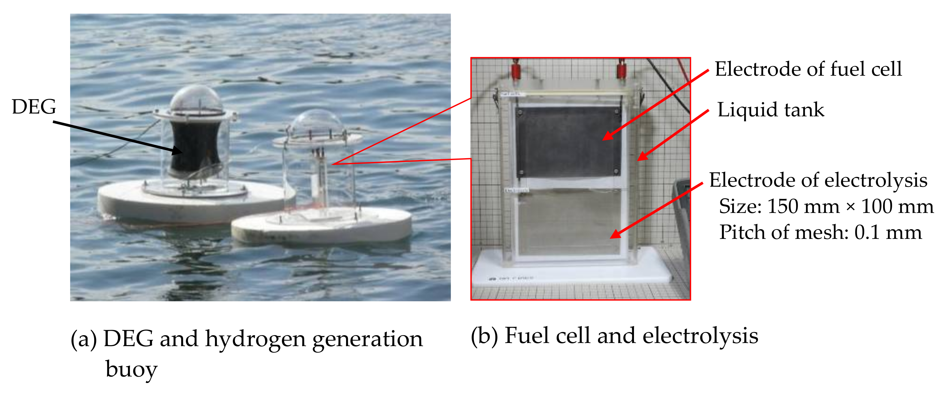
3.2.3. Production of Hydrogen

How to bring the electricity generated at sea to one’s country is a big problem. In our method, the generated electricity is electrolyzed using seawater to make hydrogen. A hydrogen generator was placed beside the above buoy power generation system, and hydrogen was produced using the power generated by the DEG [41]. Hydrogen can be a convenient medium, but the problem is its production cost. However, in wave power it’s free. Figure 19 shows the hydrogen generation equipment using electrolysis. In the very near future, electricity generated at a megawatt DE power plant built in the ocean will be converted to hydrogen and brought to Japan and other countries by tankers [22], as shown in Figure 8. Countries receiving hydrogen can use it as fuel for cars and planes, or to generate electricity using hydrogen again.

3.2.4. Combination of a Piezoelectric Power Generation System and Dielectric Elastomer Generator

DEs require an initial charge before they can start generating electricity. In addition, DEs require high direct current (DC) voltage. Therefore, we considered a self-excited DEG circuit using a piezoelectric element [47]. Piezo has the advantage of generating electricity even with slight vibrations without an initial charge.
Therefore, in the circuit we are proposing, the piezoelectric element vibrates to generate a voltage, and the generated voltage is boosted to a high voltage value by the Cockcroft–Walton circuit to charge the DE. The high voltage generated by the DE causes the ringing choke converter circuit to step down the generated voltage to a predetermined value and charge the secondary battery.
However, the problem is that the piezo output is too small. The simulation seems to work, but in reality, it is necessary to reduce the loss of the components that make up this circuit as much as possible, and further studies are required.
In wave power, there is always physical movement, and this coupling system is less powerful, but is ideal for slow-moving cases and occasionally moving slow cases.

4. Dielectric Elastomer Material

As shown in Table 1 [48], the parameters that improve the performance of DEs are the withstand voltage, dielectric constant, and Young’s modulus, etc. of the film [48]. However, when these parameters are increased, the hardness of the film increases, and the DE does not deform significantly. That is, the power obtained does not increase unless it is greatly deformed (thickness).
The point is that it should be in a balanced value rather than focusing on any one parameter. It is also important to be consistent with film forming technology and DE fabrication technology. For example, when forming the film, it is necessary to make the film thickness uniform at a considerable level, or to form the film in a clean room and make efforts to minimize dust and impurities.
In addition to the above, attempts have been made to create DEs with an elastomer with a structure that reduces the amount of dangling of the material [49] and degree of cross-linking [50], but as mentioned above, the point is the balance between them. It is not just a matter of reducing it because it is related to the strength of the film.
What Chiba et al. are paying attention to is viscoelasticity (see Figure 20) [51]. It is thought that this viscoelasticity acts as a damper (spring) and acts as a drive force that greatly deforms the DE.

4.1. Material Used for Dielectric Elastomers

Various elastomers (e.g., Table 1) have been tested for the DE [48,52]. However, it has become clear that there are some problems.
The biggest problem is that it is vulnerable to humidity [52,53]. This is especially noticeable when the temperature at which the DEs are used is high. Initially, it was pointed out that acrylic materials are vulnerable to moisture, but silicon was also found to be vulnerable. This was disappointing because silicon has a wide temperature range and researchers had high expectations for its use in wave power generations. However, it has also been found that its lifespan is extended when used at a level well below the maximum performance of the DEs. Even with acrylic materials, there are recorded cases where the DE were used up to 10 million times [52].
Chiba et al. found that putting DE in a moisture-resistant polymer bag, reducing the pressure, adding silica gel, encapsulating nitrogen, or using all of those methods would significantly extend the life [31]. Furthermore, it is important to prepare multiple DE systems and prepare for cases where some of the DEs fails.
Since the frequency of typical waves in the ocean is about 0.2 Hz, the number of DEs that move up and down by the wave in one year is about 6.3 million, so it seems that they have reached a practical stage from the viewpoint of lifespan.
There is another issue: a large DE has not yet been made. There is a diaphragm type and it has a maximum diameter of about 60 cm. Moreover, since a high voltage is required, it is necessary to modify the membrane and improve the circuit so that power can be generated at the lowest possible voltage.

4.2. Electrode Material Used for Dielectric Elastomers

As shown in Figure 10, a power generation experiment was conducted using a drape type DE having a height of 120 mm and a diameter of 260 mm. The amount of power generation when the DE was pulled by about 60 mm is summarized in Table 2 [54]. The drape weighs 4.6 g and uses acrylic material #a. Carbon black, MWCNTs (multi-walled carbon nanotubes), SWCNTs (single-walled carbon nanotubes) and high crystal CNTs were used as electrode materials.
The amount of power generated using carbon black was 284 mJ. However, changing the electrodes to MWCNTs or SWCNTs makes it possible to obtain more power, as shown in Table 2. This is because the conductivities of MWCNTs and SWCNTs are much higher than that of carbon black. As a result, as shown in Table 2, in the power generation experiment using the SWCNT electrode, the amount of power generation was about 2.3 times that of the carbon black electrode. High-crystalline SWCNTs with a superior crystal structure produced about three times as much power.
Table 2. Difference in power obtained when changing the electrode material.
Type of ElectrodePower Obtained (mJ)
carbon black 1274
multi-walled carbon nanotube445
single-walled carbon nanotube630
high crystalline SWCNT 2819
1 Carbon black and MWCNT are manufactured in companies in United States, and 2 SWCNT (ZEONANO®-SG101) and high crystalline CNT are manufactured by Zeon Corp.
Metallic CNTs are considered to be highly conductive due to their structure. Currently, Chiba et al., are starting to develop electrodes using metal CNTs. However, they are very costly at this time, so it is necessary to develop a more efficient metal CNT extraction method.

5. Summary and Conclusions

Summarizing the above results, the following could be concluded:
  • A buoy generator equipped with DEs could be able to generate electricity with high efficiency.
  • A generator equipped with DEs could be able to generate electricity in response to waves of a wide frequency range.
  • If multiple generators are placed perpendicular to the wave, each generator could absorb some of the wave energy and convert it into electricity, which in turn could weaken the wave energy. In extreme cases, it is possible to reduce the wave height to zero by deploying a significant number of generators.
  • By using a highly conductive material such as SWCNTs, the power generation capacity of the DEG is improved.
  • At a super mega power plant in the ocean, hydrogen is produced by electricity, and by tanker, the hydrogen is transported by tankers to large consumption areas. It is efficient to use the hydrogen for carbon dioxide-free fuel and/or power generation at those sites.
  • The power generation cost of an OWC equipped with a DEG on a buoy or an OWC could be about 5 US cents per 1kW.
  • Pursuing a high-performance DE is important, since by driving the DE at a lower level, it is possible to extend its lifespan.

Author Contributions

S.C. and M.W. wrote most sections of the paper. C.J. wrote the Section 3.2.1. M.T., M.U. and K.A. prepared CNTs, and decribem them in the paper. K.O. wrote some part of Section 4. All authors have read and agreed to the published version of the manuscript.

Funding

This research received no external funding.

Conflicts of Interest

The authors declare no conflict of interest.

References

  1. Institute for Sustainable Energy Policies. White Paper on Renewable Energy 2016. Available online: https://www.isep.or.jp/wp/wp-content/uploads/2017/03/JSR2016 (accessed on 20 April 2021).
  2. Proceedings of the 23rd Conference of the Parties to the United Nations Framework Convention on Climate Change (COP23), Bonn, Germany, 6–17 November 2017. Available online: www.c2es.org/content/cop-23-bonn (accessed on 20 April 2021).
  3. Carbon Dioxide Emissions Virtually Zero in 2050; Ministry of the Environment: Tokyo, Japan, 2020.
  4. Miyazaki, T.; Osawa, H. Search Report of Wave Power Devices. In Proceedings of the 2007 Spring Conference of the Japan Society of Naval Architects and Ocean Engineers, Kanazawa, Japan, 31 July–3 August 2007; pp. 43–46. [Google Scholar]
  5. Ashida, K.; Ichiki, M.; Tanaka, M.; Kitahara, T. Power Generation Using Piezo Element: Energy Conversion Efficiency of Piezo Element. In Proceedings of the JAME Annual Meeting, Tokyo, Japan, 1–4 August 2000; pp. 139–140. [Google Scholar]
  6. Asaka, K.; Okuzaki, H. (Eds.) Soft Actuators: Materials, Modeling, Applications, and Future Perspectives; Springer: Berlin/Heidelberg, Germany, 2014; Volume 13, pp. 183–195. [Google Scholar] [CrossRef] [Green Version]
  7. Yuan, X.; Changgeng, S.; Yan, G.; Zhenghong, Z. Application review of dielectric electroactive polymers (DEAPs) and piezoelectric materials for vibration energy harvesting. J. Phys. Conf. Ser. 2016, 744, 12077. [Google Scholar] [CrossRef] [Green Version]
  8. Pelrine, R.; Chiba, S. Review of Artificial Muscle Approaches. In Proceedings of the Third International Symposium on Micromachine and Human Science, Nagoya, Japan, 14–16 October 1992; pp. 1–9. [Google Scholar]
  9. Chiba, S.; Stanford, S.; Pelrine, R.; Kornbluh, R.; Prahlad, H. Electroactive Polymer Artificial Muscle. JRSJ 2006, 24, 38–42. [Google Scholar] [CrossRef]
  10. Chiba, S.; Waki, M.; Kormbluh, R.; Pelrine, R. Innovative Power Generators for Energy Harvesting Using Electroactive Polymer Artificial Muscles, 2008, Electroactive Polymer Actuators and Devices (EAPAD) 2008. In Proceedings of the SPIE; Bar-Cohen, Y., Ed.; SPIE: Bellingham, WA, USA, 2008; Volume 6927, pp. 1–9. [Google Scholar]
  11. Chiba, S.; Waki, M.; Ono, K.; Hatano, R.; Taniyama, Y.; Tanaka, S.; Okada, E.; Ohyama, K. Challenge of creating high performance dielectric elastomers. In Proceedings of the SPIE 2021 (Smart Structures and Materials Symposium and its 23rd Electroactive Polymer Actuators and Devices (EAPAD) Conference), Virtual, Online, 22–26 March 2021; pp. 1157–1162. [Google Scholar]
  12. Chiba, S.; Waki, M. The Challenge of Controlling a Small Mars Plane. In Solar Planets and Exoplanets; InTech: London, UK, 2021. [Google Scholar]
  13. Koh, S.J.; Zhao, X.; Suo, Z. Maximal Energy That Can Be Converted by a Dielectric Elastomer Generator. Appl. Phys. Lett. 2009, 94, 262902–262903. [Google Scholar] [CrossRef] [Green Version]
  14. Carpi, F.; Anderson, I.; Bauer, B.; Frediani Gallone, G.; Gei, M.; Graaf, C. Standards for dielectric transducers. Smart Mater. Struct. 2015, 24, 105025. [Google Scholar] [CrossRef] [Green Version]
  15. Jean-Mistral, C.; Basrour, S.; Chaillout, J.-J. Comparison of electroactive polymers for energy scavenging applications. Smart Mater. Struct. 2010, 19, 085012. [Google Scholar] [CrossRef]
  16. Zhong, X. Dielectric Elastomer Generators for Wind Energy Harvesting. Ph.D. Thesis, University of California Los Angeles, Los Angeles, CA, USA, 2010. [Google Scholar]
  17. Yurchenko, D.; Lai, Z.; Thomson, G.; Val, D.; Bobryk, R. Parametric study of a novel vibro-impact energy harvesting system with dielectric elastomer. Appl. Energy 2017, 208, 456–470. [Google Scholar] [CrossRef]
  18. Thomson, G.; Lai, Z.; Val, D.; Yurchenko, D. Advantages of nonlinear energy harvesting with dielectric elastomers. J. Sound Vib. 2019, 442, 167–182. [Google Scholar] [CrossRef]
  19. Moretti, G.; Papini, G.P.R.; Righi, M.; Forehand, D.; Ingram, D.; Vertechy, R.; Fontana, M. Resonant wave energy harvester based on dielectric elastomer generator. Smart Mater. Struct. 2018, 27, 035015. [Google Scholar] [CrossRef] [Green Version]
  20. Chiba, S.A.; Waki, M.; Tanaka, Y.; Tsurumi, N.; Okamoto, K.; Nagase, K.; Honma, M.; Yokota, H.; Odagiri, K.; Sato, H.; et al. Elastomer Transducers. Adv. Sci. Technol. 2016, 97, 61–74. [Google Scholar] [CrossRef]
  21. Huang, J.; Shian, S.; Suo, Z.; Clarke, D. Maximizing the Energy Density of Dielectric Elastomer Generators Using Equi-Biaxial Loading. Adv. Funct. Mater. 2013, 23, 5056–5061. [Google Scholar] [CrossRef] [Green Version]
  22. Lin, G.; Chen, M.; Song, D. Large-train, rigid-to-rigid deformation of bistable elctroactive polymers. In Proceedings of the International Conference on Energy and Environment Technology, ICEET 2009, Guilin, China, 16–18 October 2009; pp. 782–786. [Google Scholar]
  23. Brouchu, P.A.; Li, H.; Niu, X.; Pei, Q. Factors Influencing the Performance of Dielectric Elastomer Energy Harvesters. In Proceedings of the SPIE; SPIE: San Diego, CA, USA, 2010. [Google Scholar]
  24. Vertechy, R.; Papini, G.P.; Rosati, P.; Fontana, M. Reduced Model and Application of Inflating Circular Diaphragm Dielectric Elastomer Generators for Wave Energy Harvesting. J. Vib. Acoust. Trans. ASME 2015, 137, 11–16. [Google Scholar] [CrossRef]
  25. Bortot, E.; Gei, M. Harvesting Energy with Load-driven Dielectric Elastomer Annular Membranes Deforming Out-of-plane. Extreme Mech. Lett. 2015, 5, 62–73. [Google Scholar] [CrossRef]
  26. Moretti, G.; Fontana, M.; Vertechy, R. Parallelogram-shaped Dielectric Elastomer Generators: Analytical model and Experimental Validation. J. Intell. Mater. Syst. Struct. 2015, 26, 740–751. [Google Scholar] [CrossRef] [Green Version]
  27. Moretti, G.; Papini, G.P.R.; Daniele, L.; Forehand, D.; Ingram, D.; Vertechy, R.; Fontana, M. Modelling and testing of a wave energy converter based on dielectric elastomer generators. Proc. R. Soc. A Math. Phys. Eng. Sci. 2019, 475, 20180566. [Google Scholar] [CrossRef] [PubMed] [Green Version]
  28. Brochu, P.; Yuan, W.; Zhang, H.; Pei, Q. Dielectric Elastomers for Direct Wind-to-Electricity2009, Power Generation. In Proceedings of the ASME Conference on Smart Materials, Adaptive Structures and Intelligent System, Oxnard, CA, USA, 21–23 September 2009. [Google Scholar]
  29. Zhou, J.; Jiang, L.; Khayat, R. Dynamic Analysis of a Tunable Viscoelastic Dielectric Elastomer Oscillator under External Excitation. Smart Mater. Struct. 2016, 25, 025005. [Google Scholar] [CrossRef]
  30. Jean-Mistral, C.; Basrour, S.; Chaillout, J.-J. Dielectric polymer: Scavenging energy from human motion. In Electroactive Polymer Actuators and Devices (EAPAD) 2008; International Society for Optics and Photonics: San Diego, CA, USA, 2008. [Google Scholar]
  31. Chiba, S.; Waki, M. Application to dielectric elastomer materials, power assist products, artificial muscle drive system. In Next-Generation Polymer/Polymer Development, New Application Development and Future Prospects; Technical Information Association: Tokyo, Japan, 2019; Section 3, Chapter 4; ISBN-10: 4861047382, ISBN-13: 978-4861047381. [Google Scholar]
  32. Arena, F.; Daniele, L.; Fiamma, V.; Fontana, M.; Malara, G.; Moretti, G.; Romolo, A.; Papini, G.P.R.; Scialò, A.; Vertechy, R. Field Experiments on Dielectric Elastomer Generators Integrated on a U-OWC Wave Energy Converter. In Proceedings of the Ocean Renewable Energy; ASME International: New York, NY, USA, 2018; Volume 10. [Google Scholar]
  33. Kovacs, G.M. Manufacturing polymer transducers: Opportunities and challenges. In Proceedings of the SPIE Smart Structures and Materials + Nondestructive Evaluation and Health Monitoring, Denver, CO, USA, 4–8 March 2018. [Google Scholar]
  34. Pelrine, R.; Kornbluh, R.D.; Pei, Q. Dielectric elastomers: Past, present, and potential future. In Electroactive Polymer Actuators and Devices (EAPAD) XX; Bar-Cohen, Y., Ed.; SPIE: Washington, DC, USA, 2018. [Google Scholar]
  35. Chiba, S.; Waki, M.; Wada, T.; Hirakawa, Y.; Matsuda, K.; Ikoma, T. Consistent OceanWave Energy Harvesting Using Electroactive (Dielectric Elastomer) Artificial Muscle Generators. In Applied Energy; Elsevier: Amsterdam, The Netherlands, 2013; pp. 497–502. ISSN 0306-2619. [Google Scholar]
  36. McKay, T.; O’Brien, B.; Calius, E.; Anderson, I. Soft Generators Using Dielectric Elastomers. Appl. Phys. Lett. 2011, 98, 1–3. [Google Scholar] [CrossRef]
  37. Anderson, I.; Gisby, T.; McKay O’Brienl, B.; Calius, E. Multi-functional Dielectric Elas T.tomer Artificial Muscles for Soft and Smart Machines. J. Appl. Phys. 2012, 112, 041101. [Google Scholar] [CrossRef]
  38. Kessel, V.; Wattez, R.; Bauer, P. Analyses and Comparison of an Energy Harvesting System for Dielectric Elastomer Generators Using a Passive Harvesting Concept: The Voltage-clamped Multi-phase System. In Proceedings of the SPIE Smart Structures and Materials+ Nondestructive Evaluation and Health Monitoring, International Society for Optics and Photonics, San Diego, CA, USA, 8–12 March 2015; p. 943006. [Google Scholar]
  39. Zurkinden, A.; Campanile, F.; Martinelli, L. Wave Energy Converter through Piezoelectric Polymers. In Proceedings of the COMSOL User Conference 2007, Grenoble, France, 23–24 October 2007. [Google Scholar]
  40. Chiba, S.; Waki, M.; Fujita, K.; Song, Z.; Ohyama, K.; Zhu, S. Recent Progress on Soft Transducers for Sensor Networks. In Technologies and Eco-Innovation toward Sustainability II; Hu, A.H., Ed.; Springer Nature: London, UK, 2019. [Google Scholar] [CrossRef]
  41. Chiba, S.; Kornbluh, R.; Pelrine, R.; Waki, M. Low-cost Hydrogen Production from Electroactive Polymer Artificial Muscle Wave Power Generators. In Proceedings of the World Hydrogen Energy Conference 2008, Brisbane, Australia, 16–20 June 2008. [Google Scholar]
  42. Chiba, S.; Waki, M.; Masuda, K.; Ikoma, T.; Osawa, H.; Suwa, Y. Innovative 2012, Power Generation System for Harvesting Wave Energy, Design for Innovative Value Towards a Sustainable Society; Springer: Amsterdam, The Netherlands, 2012; pp. 1002–1007. ISBN 978-94-007-3010-6. [Google Scholar]
  43. Chiba, S.; Waki, M.; Masuda, K.; Ikoma, T.; Osawa, H.; Suwa, Y. Innovative Wave Power Generator Using Dielectric Elastomers Artificial Muscle. In Proceedings of the World Hydrogen Technologies Convention-2011, Glasgow, Scotland, UK, 14–16 September 2011. [Google Scholar]
  44. Chiba, S.; Hasegawa, K.; Waki, M.; Kurita, S. An Experimental Study on the Motion of Floating Bodies Arranged in Series for Wave Power Generation. J. Mater. Sci. Eng. A 2017, 7, 281–289. [Google Scholar] [CrossRef] [Green Version]
  45. Jiang, C.; Chiba, S.; Waki, M.; Fujita, K.; Moctar, O. An Investigation of Novel Wave Energy Generator Using Die-Lectric Elastomers. In Proceedings of the ASME 2020 39th International Conference on Ocean, Offshore and Arctic Engineers, Virtual, Online, 3–7 August 2020. OMAE-18106. [Google Scholar]
  46. Mitsumasa, I.; Miyazaki, T.; Iida, M. Estimation of Cumulative Output Energy of Oscillating Water Colum Wave Energy Converter Considering Power Take Off Damping. In Proceedings of the ASME 2020 39th International Conference on Ocean, Offshore and Arctic Engineers, Virtual, Online, 3–7 August 2020. OMAE-19172. [Google Scholar]
  47. Sakano, T.; Ohyama, K.; Zhu, S.; Waki, M.; Chiba, S. Experimental verification of a self-excited power generation system for dielectric elastomer generation using piezoelectric elements. In Proceedings of the SPIE Smart Structures + Nondestructive Evaluation, Online, 27 April–9 May 2020. [Google Scholar]
  48. Pelrine, R.; Kornbluh, R.; Joseph, J.; Heydt, R.; Chiba, S. High-field defomation of elasomeric dielectrics for actuators. In Proceedings of the 6th SPIE Symposium on Smart Structure and Materials, Newport Beach, CA, USA, 1 March 1999. [Google Scholar]
  49. Kumamoto, H.; Hayashi, T.; Yonehara, Y.; Okui, M.; Nakamura, T. Development of a locomotion robot using deformable dielectric elastomer actuator without pre-stretch. In Proceedings of the SPIE Smart Structures + Nondestructive Evaluation, Online, 27 April–9 May 2020. [Google Scholar]
  50. Hu, P.; Huang, Q.; Madsen, J.; Skov, A.L. Soft silicone elastomers with no chemical cross-linking and unprecedented softness and stability. In Proceedings of the SPIE Smart Structures + Nondestructive Evaluation, Online, 27 April–9 May 2020. [Google Scholar]
  51. Li, W.; Zhu, S.; Ohyama, K.; Chiba, S.; Waki, M. Mechanical properties and viscoelasticity of dielectric elastomers. In Proceedings of the Materials and Mechanics Conference, Japan Society of Mechanical Engineers, Sapporo, Japan, 7–9 October 2017. [Google Scholar]
  52. Kornbluh, R.D.; Pelrine, R.; Prahlad, H.; Wong-Foy, A.; McCoy, B.; Kim, S.; Eckerle, J.; Low, T. From boots to buoys: Promises and challenges of dielectric elastomer energy harvesting. In Proceedings of the SPIE Smart Structures and Materials + Nondestructive Evaluation and Health Monitoring, San Diego, CA, USA, 6–10 March 2011. [Google Scholar]
  53. Albuquerque, F.B.; Shea, H.R. Effect of humidity, temperature, and elastomer material on the lifetime of silicone-based dielectric elastomer actuators under a constant DC electric field (Conference Presentation). In Proceedings of the SPIE Smart Structures + Nondestructive Evaluation, Online, 27 April–9 May 2020. [Google Scholar]
  54. Chiba, S.; Waki, M.; Takeshita, M.; Uejima, M.; Arakawa, K. Dielectric elastomer using CNT as an electrode. In Proceedings of the SPIE Smart Structures + Nondestructive Evaluation, Online, 27 April–9 May 2020. [Google Scholar]
Figure 1. Basic operational principle of dielectric elastomers (DEs).
Energies 14 03414 g001
Figure 2. DE actuator (DEA) with a weight of 8 kg.
Energies 14 03414 g002
Figure 3. Expanding circular actuator up to 680%.
Energies 14 03414 g003
Figure 4. DE power generation principle: (a) the DE elastomer film is being stretched by hand; (b) when the hand pulling force is loosened, the film will return to its original length.
Energies 14 03414 g004
Figure 5. Schematic diagram of the power generation cycle.
Energies 14 03414 g005
Figure 6. Measurement circuit of the voltage of a dielectric elastomer generator (DEG) in a contracted state.
Energies 14 03414 g006
Figure 7. Measurement circuit of the capacitance of a DEG in a contracted state.
Energies 14 03414 g007
Figure 8. A conceptual diagram of various power generation systems using DEGs.
Energies 14 03414 g008
Figure 9. The world’s first DE wave power generation system: (a) The beat plate was moved by waves, the movement was transmitted to the sheet-type DE installed on the side of the tank, and the force was used to expand and contract the DE to generate electricity; (b) The photo on the right is a beat-type floating body.
Energies 14 03414 g009
Figure 10. Buoy power generator system equipped with DEGs: (a) Name of each part of the wave generator buoy; (b) A photo of a generator buoy that actually floated in the sea.
Energies 14 03414 g010
Figure 11. Drape type DE generator: The amount of the DE used is 4.6 g: (a) Relaxed states; (b) Stretched state.
Energies 14 03414 g011
Figure 12. Buoy power generation system with plate.
Energies 14 03414 g012
Figure 13. Image diagram of the power generation system installed in the ocean: (300 MW/H can be obtained with a system with a width of 40 m and a length of 600 m). One could arrange a large number of these to make a super megawatt power generation system.
Energies 14 03414 g013
Figure 14. Wave generator with miniaturized circuit, etc.: (a) The generator buoy actually floating in the sea; (b) Name of each part of the buoy.
Energies 14 03414 g014
Figure 15. Motion of the body influenced by waves: (a) vertical motion of the buoy; (b) horizontal motion of the buoy.
Energies 14 03414 g015
Figure 16. Experimental set-up: The DEG was set between a mooring rope and the floating body. Details of the generator unit are shown schematically at the left while the photos at the right show the overall system set-up. The DE material was acrylic #a: (a) DEG unit; (b) Buoy with the DEG; (c) Wave-making tank and measurement system.
Energies 14 03414 g016
Figure 17. Generated energy as a function of wave period.
Energies 14 03414 g017
Figure 18. A test system to investigate how the waves interfere with each of the three buoys.
Energies 14 03414 g018
Figure 19. The hydrogen generation equipment using electrolysis: (a) DEG and hydrogen generation buoy; (b) Fuel cell and electrolysis.
Energies 14 03414 g019
Figure 20. Stress strain hysteresis loops of: (a) acrylic elastomer; (b) silicone elastomer with strain from 100 to 200%.
Energies 14 03414 g020
Table 1. Maximum response of representative elastomers.
Polymer
(Specific Type)
Elastic Energy Density
(J/cm3)
Pressure
(MPa)
Strain (%)Young’s Modulus (MPa)Breakdown Electric Field
(V/μm)
Dielectric Constant
(at 1 kHz)
Coupling Efficiency, k2 (%)
Acrylic #a3.47.21582.04124.885
Silicone #a0.221.361021.02352.854
Polyurethane #a0.0871.66017.01607.021
Silicone #c0.0820.51320.71442.854
Fluorosilicone #10.0550.39280.5806.948
Silicone #b0.0260.13410.125722.865
Isoprene Natural Rubber #a0.00590.11110.85672.721
Fluoroelastomer #a0.00460.1182.53212.715
1 Average engineering modulus at the maximum strain; The above films used were elastomers commercially produced by several companies in the United States.
Publisher’s Note: MDPI stays neutral with regard to jurisdictional claims in published maps and institutional affiliations.

