Abstract
The time-range of applicability of various energy-storage technologies are limited by self-discharge and other inevitable losses. While batteries and hydrogen are useful for storage in a time-span ranging from hours to several days or even weeks, for seasonal or multi-seasonal storage, only some traditional and quite costly methods can be used (like pumped-storage plants, Compressed Air Energy Storage or energy tower). In this paper, we aim to show that while the efficiency of energy recovery of Power-to-Methane technology is lower than for several other methods, due to the low self-discharge and negligible standby losses, it can be a suitable and cost-effective solution for seasonal and multi-seasonal energy storage.
1. Short and Long Time Energy Storage
The purpose of energy storage is to store unused electricity for later use. The use can be done by recovering the available part of the stored electricity and using it. However, due to legislative changes, when the intermediate product (e.g., hydrogen) of the storage process is a fuel, it is also considered energy storage [1]. In the current article, we only consider the variant where both input and output become electricity; the possibility of using it as a fuel is only mentioned as an extra option where relevant.
Storage can be achieved in many different ways [2,3]; the simplest would perhaps be to store the electricity as electricity without modification (in supercapacitors or superconducting rings), but these solutions are generally expensive and have relatively small storage capacities.
Fortunately, there are other solutions with lower cost and/or larger storage capacity, but these methods require the electricity to be converted into another form of energy and then converted back. This back-and-forth conversion is costly and requires special equipment or facilities. One of these methods is mechanical energy storage, where the stored electricity is converted into either potential (e.g., pumped storage reservoirs) or kinetic (e.g., flywheel reservoirs) energy, and then this potential or kinetic energy is converted back into electricity using generators. Energy can also be stored chemically, using the initial electricity to produce a fuel or to increase the energy content of an existing fuel. Perhaps the best-known form of this group is the production of hydrogen by electrolysis of water, where the hydrogen can be stored and then used to recover electricity later in time, e.g., using fuel cells. For historical and technological reasons, electrochemical storage is a separate category, where reversible electrochemical processes are used to store and recover the energy; this is how rechargeable batteries work. We should also mention the so-called heat accumulators; heat accumulation is not usually classified as energy storage because usually neither the input nor the output “product” is electricity. Nowadays, this is changing. Sometimes there is so much excess electricity production, it is worth using it to produce heat and using it later (the input is then electricity). It is then possible—albeit with low efficiency—to produce electricity from the heat again later, e.g., by using the heat for the input of an Organic Rankine cycle [4].
Energy storage is mainly needed to compensate for the difference between fluctuating energy production (mostly caused by the changing weather condition) and fluctuating demand. As shown by Hiesl et al. in EUROSTAT data [5], the percentage of renewable-based electricity (excluding conventional hydropower) in the EU-28 has increased from 1% to 20%. In relative terms, the largest increase over the period was for solar (PV) generation. For these renewables (biomass, biogas, bio-liquid and other bio-derived waste, wind (off- and on-shore type), tidal, geothermal) and for the conventional, i.e., river-based—hydropower (not included in the survey), the weather dependence can be clearly observed. This dependence can lead to large variations in production even in the short term for solar and wind, but in other cases, a longer-term dependence can also be observed. For example, in the case of biological materials, the production of raw materials (quantity as well as quality) depends on the weather on a seasonal basis, while in the case of conventional hydropower, production is also affected by the weather (rainfall, drought) over a period of seven to ten months or seasonally. Surprisingly, even geothermal electricity generation is weather-dependent. For example, in ORC-based power plants, which are often used on these heat sources, the condenser temperature and the efficiency of the whole power plant are affected by weather-dependent variations in air or surface water [6].
In relation to storage or balancing problems, due to weather dependency, we tend to think of problems and solutions related to sub-hourly basis (e.g., clouds before the sun), daily basis (solar panels do not produce at night) or weekly basis (the drop in industrial consumption on Saturday-Sunday). For such storage tasks (both in terms of duration and capacity), battery-based systems such as Li-ion can be used. However, these types of storage are not suitable where seasonal (due to winter-summer production and consumption differences) or possibly longer-term (several years) storage is required, i.e., the task is actual storage, not the regulation of current fluctuations. One reason is their self-discharge, which causes the energy stored in them to decrease continuously and another is the very high storage capacity requirements that occur when storing on a seasonal or annual basis.
The discharge time (very often mislabeled as storage time, but storage can happen both in loaded or unloaded conditions) is often used to indicate how long the currently marketed types of a given storage method would be able to continuously supply the connected consumer, such a diagram is shown in Figure 1.
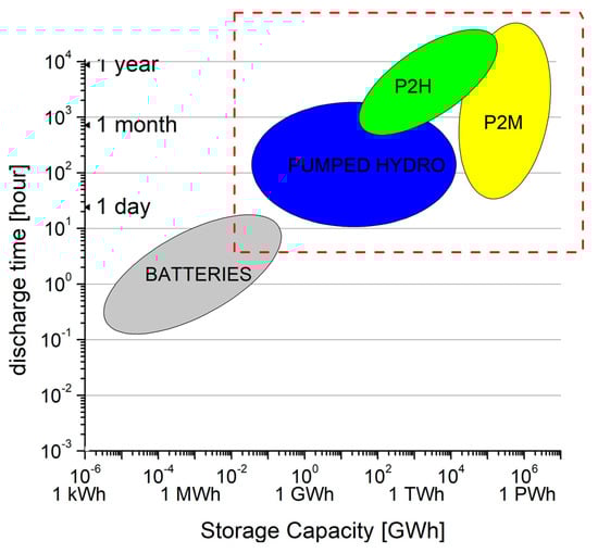
Figure 1.
Schematic discharge time vs. storage capacity diagram for various storage methods, including batteries, pumped hydro, Power-to-Hydrogen and Power-to-Methane [5]. Long-term storage solutions are located inside the dashed rectangle.
Using this kind of diagram, one can decide that what would be the available storage solutions to provide the average need for a given consumer (or group of consumers) for a given length of time, under normal discharging conditions. For example, for a consumer who needs 100 GWh electricity to cover its expected consumption for a month, pumped hydro- or Power-to-Hydrogen methods would be viable solutions, being the (100 GWh; 1 month) point in the common part of the green and blue region.
For discharge time—storage capacity diagrams, the output power is usually not defined. Although, it makes a difference whether a storage system has to supply a small residential building or an entire industrial estate. It is usually assumed that the maximum power or close to the maximum power of the already existing storage systems; the uncertainty in this is well hidden by the double logarithmic nature of the diagram. As an example, a commercially available 21 tons, container-sized sodium sulphur (NaS) battery unit has a maximum storage capacity of 1.2 MWh. The maximal charge/discharge power is 200 kW, but occasionally only half of this power is used [7]; thus, the discharge time is 6–12 h. So this type would be a small “blob” with a not sharp boundary between 1–1.2 MWh and 6–12 h within the grey ellipse in a discharge time vs. storage capacity diagram (Figure 1). From this figure, it is possible to determine how long a fully charged storage can supply the consumer from the start of discharge, assuming a more or less constant (or, because of the logarithmic scale, at least one order of magnitude) power output.
Another time-related descriptor used for energy storage is the lifetime of the equipment itself. This is often given in terms of a maximum number of cycles (a cycle is a charge and discharge), in which case the lifetime can be obtained by multiplying this number of cycles by the average charge-discharge time. Another lifetime is the so-called shelf-life [8], showing the deterioration of a storage device from brand new to unusable, holding it in unused (and usually discharged or just partly charged) condition. The shelf-life is mainly given for batteries; many people are interested in how long an unused battery can be used, but less so in how long the dry bed of an unused pumped storage reservoir remains impermeable.
In this article, we would like to introduce a novel time-dependent quantity, which is not only time-dependent but also storage efficiency-dependent. This quantity shows that by filling a given type of storage and then storing it for t time after filling (without deliberate discharge, i.e., allowing only self-discharge), we get back a fraction of the energy stored as a function of time. This quantity will be important for seasonal, annual or multiannual storage, as it is not always the case that the photovoltaic energy, produced during a hot summer, can be recovered after 3–4 months (i.e., within a season) of unused storage.
In this paper, it will be proved that among the large-capacity storage methods, if the storage period exceeds half a year to one year, the so-called Power-to-Methane technology (in which methane is produced from water and carbon dioxide using stored electricity and then used to generate electricity at the time of storage) currently appears to be the most promising, from energetic and probably an economic point of view.
2. The Actual Discharge State Function
In this section, we introduce a novel quantity to help us to describe the actual state (the recoverable energy) for a given energy storage system. To understand the role of this new quantity, we need to generalize the term “self-discharge”, which is mainly used for supercapacitor or battery storage. In self-discharge, the amount of energy stored in a storage device decreases even when it is unloaded; this usually happens in batteries due to a particular chemical reaction. For most battery types, this is a few tenths of a percent per day, but in some cases (such as in the case of a switched on redox liquid flow battery), it can be as much as 10% per day.
The generalization can be done in two different ways. First, in some cases, the so-called standby energy losses, which characterize the consumption of auxiliary equipment necessary for the operation of the storage, cannot be physically separated or should not be separated from the self-discharge losses; see, for example, the case of a sodium-sulphur battery. In this type, the dissipation heat of the self-discharge processes keeps the sodium and sulphur electrodes liquid during the 6–12 h charge-discharge cycles. While in a case where neither charge nor discharge occurs, this has to be done by an auxiliary heater, causing a loss of about 3% per day. The two types of losses can be physically separated, but since the effects of the two losses are the same, the separation does not make sense.
The second way to generalize the concept of self-discharge is the extension from capacitors and batteries to other storage devices. It is easy to see that evaporation and leakage losses in a pumped hydro storage, leakage of gas in a power-to-gas storage, leakage of the liquid or the degradation of the usually complex molecular structure in a power-to-liquid storage will cause losses similar to self-discharge of batteries, which are also time-dependent. Such losses can occur even in weight storage, although in the short term they may be due to a more random process (e.g., a few stones falling off a railway wagon used as weight storage), but over extremely long storing times, they may be of a more general nature (e.g., concrete elements of an abandoned weight tower start to crumble and erode).
The loss accumulates over time and is therefore given in units of percentage or part normalized to time (e.g., %/day), but this is only possible if the loss is stationary in time. When the speed of loss is not constant, it would be more appropriate to use a self-discharge function. If the strictly time-dependent self-discharge and other losses are summed, a time-dependent total storage loss can be obtained. Subtracting this from the amount of energy stored gives the energy that can be recovered from the storage. In this way, one can obtain an already time-dependent storage efficiency:
where Esd(t) is the time-dependent self-discharge function, Esb(t) is the time-dependent standby loss function, Eini is the time-independent stored energy (at t = 0), and ηs(t) is the now time-dependent storage efficiency including all losses and the discharging efficiency; this is what we call the Actual Discharge State Function or ADSF, which is a time-dependent function, correctly marked as ADSF(t).
Now, the recovered energy (i.e., the amount recovered after full discharge) is
where Ed(t) (subscript d stand for discharge) is also turns into a time-dependent quantity.
If the same amount of energy (for example, one “unit”) is stored in two different types of storage devices, the ADSF(t) function gives the fraction of this energy that can be recovered if the discharge is started only t time after fully charging them; the two devices were unloaded during this t time, and the stored energy was reduced only by the generalized self-discharges. By comparing the ADSF(t) functions of these two storage facilities, it is easy to see which one will recover more energy later, starting the full discharge at any given time. This is demonstrated in Figure 2.
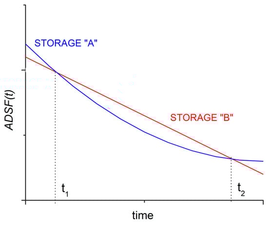
Figure 2.
Using the time-dependent function ADSF(t), it can be decided which kind of energy storage device is preferable when the discharging of the fully charged storage devices is started after an unloaded period. Starting discharge before time t1, then storage A is better, starting discharge between t1 and t2, storage B is preferable while starting the discharge after t2, storage A would again recover more electricity.
Obviously, besides the ADSF(t) function, there are other quantities to be considered by choosing the proper storage technology, such as:
- -
- installation and operating costs
- -
- environmental and social criteria (pollution, social acceptance, etc.)
- -
- power density
- -
- energy density, total energy storage capacity.
Only the latter two are considered here. When comparing the ADSF(t) function of two or more storage facilities, it will be indicated separately if one of them require an extremely large storage size to store the same amount of energy (energy density) or if it is not possible to build a storage size larger than a certain size for physical, economic or other reasons (e.g., the rarity of vanadium would make it difficult to build extra large vanadium redox storage facilities).
The ADSF(t) function presented here is somewhat similar to the shelf-life, which is a time-independent but time-dimensional value given by manufacturers for batteries, referring to how long the storage device is functional when stored in an unloaded state. This quantity should also be time-dependent since it is possible that after six months, for example, the battery’s storage capacity is 80% of the original capacity, while after 12 months, it is 60%. How long the storage device is considered to be usable also depends on the use; in some circumstances, 80% is not worth it for the user (in that case, the shelf-life of less than 6 months), in others cases, 60% is more than enough (in this case, shelf-life would be more than 12 months). The secondary use of batteries of electric cars is a good example, where after a while, they no longer fit for their original purpose but are still suitable for other purposes. Therefore, the original time-independent shelf-life (tsl) can be generalized to obtain a time and remaining storage efficiency-dependent new shelf-life, where the latter “variable” could be a given limit value rather than a real variable. For example, the data pair of ( = 1 year; = 2 years) that a given storage device would still be able to work on 60% of its original storage capacity after 1 year, and only 20% after two years).
An important distinction is that while the shelf-life is a quantity related to the unloaded storage facility (and this is also true for the time-dependent version), the ADSF(t) function refers to the stored energy (also in unloaded state), which of course is also affected by the storage facility. Therefore, one can say that it is something, like the shelf-life of the stored energy.
Concerning the ADSF(t) function, for a given storage method, it can consist of several different time-dependent and time-independent parts. For example, in a pumped reservoir, the “self-discharge” itself introduces such terms; the evaporation loss depends on the external temperature and wind (this is time-dependent) and the current free surface area of the reservoir (this may be constant, but in dam reservoirs, it usually decreases as the volume in the reservoir decreases), while the seepage loss depends on the volume of water in the reservoir (the head of the water column, i.e., the pressure). Such a complex function is difficult to model, so for our comparison, we use a simplified (linear) ADSF(t) function. In this case, the time-dependent storage efficiency (ηs(t)) defined in Equation (1) will have a time-independent term (ηs) and a linear form of time-dependence. Therefore, the linearized ADSF(t) function takes the following form:
where, just like before, ηb is the efficiency of the conversion of stored energy back into electricity (i.e., the round-trip efficiency) and t is the time. In such a case, the curves in Figure 2 would become linear, and there would be only one intersection for two storage facilities, giving the time over which one reservoir is better for shorter storage and the other for longer storage. In this form, it can be seen that if we start discharging immediately after recharging (e.g., if we want to smooth PV output due to solar irradiance irregularities with a Li-ion battery), the ADSF(t = 0) is equal to the efficiency of converting the stored energy back to electricity, and then decreases linearly from there.
It can be seen that the actual ADSF(t) value for a given time can be increased in two ways; either by increasing the efficiency of the conversion efficiency upon discharge (e.g., in the Power-to-Methane case, by recovering the waste heat from the gas engine performing the conversion back in an ORC [9,10]), or by slowing the decrease, by reducing self-discharge (e.g., by better, more leakage-free storage of hydrogen in the case of Power-to-Hydrogen) or by reducing standby losses, such as in liquid electrode batteries by reducing heat loss through better insulation.
In the next section, some storage technologies are going to be presented by comparing their simplified (linear) ADSF(t) function to select which methods perform better than others for longer storage times. Then, based on the above two secondary criteria (energy density, total energy storage capacity), we will show which is the time interval of our interest (seasonal to multi-annual), the Power-to-Methane storage is likely to be the most appropriate.
3. Comparison of Various Energy Storage Methods
In this paper, we compare a few of the more well-known battery types, two Power-to-Gas storage types and one weight storage type. The traditional method for seasonal storage, pumped storage, is not considered here. On the one hand, its installation requires special natural conditions (i.e., it cannot be installed anywhere) [11], and on the other hand, there are countries (like Hungary), where installation of such kind of devices are strongly opposed for historical-political reasons [12].
Since the main objective is to place Power-to-Methane storage in the storage chain, the other types are only briefly described.
3.1. Batteries
The ADSF(t) functions of the following battery types will be discussed in this section:
- -
- Lead-acid battery
- -
- Nickel-metal hydride battery
- -
- Lithium-ion (LiNMC/LiFePO4) battery (new as well as second-life)
- -
- Vanadium redox flow battery (in standby mode with flowing electrolyte and in offline mode with disconnected storage tanks)
- -
- Sodium-sulphur (NaS) battery
We do not describe the first three types here in detail; all three types are well known, frequently used, and their characteristics can be found in the literature [3]. The values relevant for the estimation of the linearized ADSF(t) functions are given in Table 1.

Table 1.
Constants of the simplified (linear) ADSF(t) function (Equation (3)). The values shown are for the best commercially available models for the type; some manufacturers’ products may perform better or worse than this. Limits for these values are shown in Supplementary Materials Table S1.
Concerning Li-ion battery; this type is mostly used when high energy- and power-densities are needed; therefore bigger capacity Li-ion batteries are used mostly in transportation. For utility-scale seasonal storage, they would be “too good”; therefore, for this purpose, we are considering “second-life” batteries. These are batteries too much deteriorated for their original use, but still applicable for other purposes [13].
In the vanadium redox flow battery (VRFB), the chemical reaction takes place in a space, separated by a membrane (see Figure 3). Vanadium ions are present in the electrolyte in concentrations of a few mol/L, and the electrochemical reactions happen between different chemical valence states (V2+/V3+ or V5+/V4+). The two types of electrolyte are stored in two separate tanks and can only come into contact with each other in the reaction space separated by a membrane. In practice, this type of battery is a small chemical factory; when the “intermediate products” are not required, the two types of electrolyte are stored without degradation, leakage or evaporation (i.e., self-discharge) in tanks, of which there may be more than one, and they may even be separated from the central, power-generating unit (i.e., as if they were liquid fuels in separate tanks). In this case, the battery is in a disconnected, offline state (the electrolyte is not circulated), with virtually zero self-discharge (until the plastic tanks break down and the electrolyte drains away). However, if it is flowing (i.e., it is in standby mode, ready for discharge), the daily self-discharge can be as high as 20%. The efficiency of the recovery is between 75–80%, including standby losses (e.g., pump operation in this case).
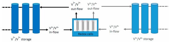
Figure 3.
Schematic diagram of a Vanadium Redox Flow Battery with extendable and disconnectable electrolyte storage tanks.
The sodium-sulphur (NaS) battery is a high-temperature, molten electrolyte battery; while the two electrodes (sodium and sulphur) are in a liquid, i.e., molten, state, the electrolyte is solid [7,14,15]. The internal temperature of the battery is at least 300 °C to keep the electrodes in liquid state. The battery belongs to the so-called energy batteries. Whereas, in power batteries (such as Li-ion batteries) the energy is delivered quickly (i.e., at high power), and for this type, the power is lower, but the total amount of energy stored is high. They are commercially available in container size; those made by NGK Insulators Ltd. of Japan can store 1.2 MWh and deliver this in six hours (or more) at a maximum power of 200 kW. The high temperature is provided by the dissipation heat generated by the self-discharge during continuous charge-discharge cycles. The overall conversion efficiency can in principle, reach 85%. In the unloaded state, one has to face a standby loss due to the necessary heating provided from the stored energy is 3.4 kW, i.e., 81 kWh per day, or 6.8% [16].
3.2. Power-to-Gas Type Storage Systems
In Power-to-Fuel storage [3], electricity is used to produce a new fuel or convert an existing fuel to another with higher energy content. We are dealing with two sub-types within the method, both of them belonging to the Power-to-Gas group (i.e., the fuel produced is gaseous); one is hydrogen (Power-to-Hydrogen, P2H), and the other is methane (Power-to-Methane, P2M). The two methods are very closely related; in both cases, hydrogen is produced in the first step by hydrolysis using surplus electricity (to be stored). In the P2H method, that hydrogen is later used to generate electricity or as a vehicle fuel (but we are only looking at the electricity-storage-electricity type of methods). In pure form, it can be stored as a high-pressure gas or cryogenic liquid until reuse; alternatively, it can be stored in chemically bonded form (e.g., as ammonia) or mixed with natural gas [17,18]. In this method, the loss of hydrogen is responsible for the “self-discharge”; to estimate this value, we are considering high-pressure gas storage and cryogenic liquid storage separately.
In the P2M method, the hydrogen (produced by electrolysis using the surplus energy) and carbon dioxide (used from various sources) are used to produce methane by chemical [19] or biochemical [20] means; after the storage, the methane is used to generate electricity or as a vehicle fuel. In the present article, the biochemical version, which is less energy-intensive and therefore more efficient, is considered. It also has the advantage of being suitable for enriching methane-carbon dioxide mixtures (biogas, landfill gas) because, due to the low temperature, it can preserve the methane already present in the input gas. For conversion back to electricity, we are estimating a methane-to-electricity method of about 60% efficiency (e.g., an improved gas turbine), which gives a total storage efficiency of about 33%. It is also possible to convert the waste heat of electrolysis and methanization (approximately 30% of the incoming energy are lost in these two steps, part of these losses happens in the form of 60–70 °C waste heat) back into electricity by a low-temperature ORC process [21] and fed back into the electrolyzer, reducing the amount of energy input and thus increasing the storage efficiency with 1–2%. Also, it is possible to utilize the waste heat produced upon the recovery of the electricity, using a second ORC equipment. In this way, one might assume an upper limit for overall storage efficiency around 50%; we are discussing the two cases (33% and 50%) separately. In both cases, the methane would be stored in the natural gas network; the self-discharge, is thus, leakage from the network, the value of which was estimated from other data [22,23]. The steps of the whole cycle can be seen in Figure 4.
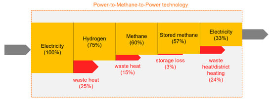
Figure 4.
The steps of the Power-to-Methane-to-Power cycle; efficiencies and dissipative losses are marked.
3.3. Comparison of the Various ADSF(t) Functions
Relevant quantities to estimate the linearized ADSF(t) functions for the storage technologies discussed here are listed in Table 1.
Based on these data, the ADSF(t) vs. time function (Figure 5) can be plotted, showing what percentage of the initially stored electricity can be recovered (also as electricity) when the fully charged storage is discharged after an unloaded condition of t time. Because efficiencies can be different for various products within one type, thus, on Figure 5a,b, best and worst scenarios are marked for methods, where the efficiencies are moving in a wide range. Concerning these scenarios, we are considering only commercially available models. In Figure 5c, the most realistic scenarios are compared, based on the averaged data of Table 1. For hydrogen (P2H), the range shown is for small and large containers, where heat loss (and therefore liquid-loss) depends on the size-dependent surface-to-volume ratio.
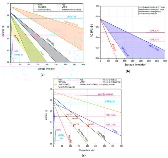
Figure 5.
Comparison of simplified (linear) ADSF(t) functions of the relevant storage methods. (a): Comparison of various battery types (marking the best and worst scenarios); (b): Similar diagram for the available Power-to-Gas methods; (c): comparison of the methods using data of the best commercially available models. The intersection points indicate which storage method is energetically better for storage times shorter than the corresponding duration or longer than the corresponding no-load storage time. The four red dots indicate the times for which the Power-to-Methane method may be energetically good for longer duration storage.
As shown in Figure 2, when two curves (or lines) intersect, it can be seen that for storage shorter than the time corresponding to the intersection point, where one is the more energetically advantageous solution for storages involving shorter times, while the other is better for longer storage times. As shown in Figure 5c, certain types (gravitational storage, offline vanadium redox flow battery) are very advantageous for long term energy storage; their disadvantages related to other criteria will be discussed in the next section. Also, lead-acid batteries and second-life Li-ion batteries (at least the better ones) seem to be a good solution; half of the energy stored during the summer can be recovered after 2.5–5 months. A storage system supplying a Hungarian municipality of 10,000 inhabitants (based on energy demand of 4260 kWh/person/year) for three winter months is 10.65 GWh; it would be difficult to build a storage system of this size with these types of storage (numbers would be similar for most of the countries). For Li-ion batteries, the main limitation is the amount of lithium needed. This problem is further escalated by the fact that, unlike many other types, Li-ion batteries are also well-suited to transport applications, where they are in high demand leaving less batteries for utility-scale storage. Additionally, the relatively short lifetime of Li-ion batteries (<10 years, even with the second-life period) makes this type hardly applicable for multi-annual storage. For lead batteries, the potential environmental hazards would perhaps be the primary reason not to build such a storage facility.
Red dots indicate the time limits when P2M storage will be than these batteries. This occurs after around 118 days for 33% recovery (P2M-33%) compared to Li-ion batteries and after about 205 days compared to acid lead batteries; these values change to 76 and 138 days for 50% recovery (P2M-50%). In other words, for seasonal energy storage, where storage would mostly occur in July-August and use in December-February, i.e., 100–200 days later (electricity would have to be stored in an unloaded state until then), P2M method is already competitive with most other storage methods even at the 33% total storage efficiency that is currently easily achievable; the two exceptions to the types discussed are the gravitational storage and the offline vanadium redox flow battery. A comparison with these methods is the subject of the next sub-section.
The other types of storage considered (NaS battery, circulating VRFB battery and hydrogen storage with both liquid and gas storage) are not suitable for seasonal, annual or multi-annual storages.
3.4. Comparison of High-Capacity Storage Solutions Applicable for Long-Time Storage
Based on the previous calculations, for seasonal to multi-annual storage, the Power-to-Methane method has two competitors, the gravity storage and the offline VRFB, where the liquid electrolyte tanks are separated from the central cell. Therefore, self-discharge is reduced practically to zero. The offline VRFB will not be competitive; vanadium is even more difficult to obtain than lithium, so for the 10 GWh demand of the town mentioned above, the production of 400,000 m3 of solution with a concentration of at least 1 mol/L vanadium compound at a volume energy density of 25 Wh/L does not seem realistic.
A more serious challenge is the solid gravity storage, like mass- (or weight-) towers. Gravity storage is similar in principle to pumped storage in that it stores energy in the form of potential energy and can be recycled with high efficiency. Although there are some types that can only be installed in certain locations (e.g., hillsides [24] or mines [25]), energy tower-type versions [26] could be installed almost anywhere. In the energy tower, concrete blocks are stacked using a special crane; in this way, the electricity turns to potential energy. When discharged, the crane lowers these blocks to ground level, while a suitable transmission system generates electricity with a built-in generator. Self-discharge is difficult to understand in such storage, although in the long term, the falling or erosion of the stored blocks may cause such a loss. Since no numerical data were available, we looked for a long-standing tall structure built of heavy blocks and used it to investigate the reduction in stored energy over a sufficiently long period of time; from this, we were able to estimate the daily ηs value.
The studied “solid gravity storage” system is the Cheops pyramid; its original height is estimated at 146.7 m, now 138.8 m. Its current mass is about six million tons, its volume 2.3 million cubic meters, and its age is about 4500 years. We approximated both the original and the current version as a regular pyramid; the size of the bases was assumed to be constant, and the loss was calculated from the loss of mass and height. Therefore, the energy stored was about 634 MWh, and the current energy content was 567 MWh, a “self-discharge” of 10.5% over the whole lifetime, which is 6.4 × 10⁻⁶ per day, or 0.00064%/day, practically comparable to P2M methods, but the big advantage is the long lifetime in the “no load” condition, which in this case exceeds 1000 years.
A serious physical disadvantage of this type (the financial side is not considered in this article) is the large size due to the low energy density. With a medium-quality gas turbine, it would require about 75 tons of methane (natural gas) to produce the energy stored in such a gravity storage system. This is 0.00125% of the pyramid by mass, which is about 170 m3 in liquid storage (LNG), about 420 m3 in high-pressure storage (CNG, 200-250 bar) and about 100,000 m3 at normal pressure. In other words, a Cheops pyramid-sized atmospheric pressure reservoir would have a storage capacity as a P2M reservoir of about 23 times that of a gravity reservoir, shifting this ratio even more at higher pressures; moreover, with P2M method, a pyramid would not need to be dismantled and built seasonally.
Power-to-Methane technology appears to be the best technical solution for seasonal, annual and multi-annual storage of large amounts of energy. It is important to note that this is an economically and socially acceptable method, which also fits well with the existing storage and electricity generation infrastructure [27,28,29].
Our aim was to show that there is a segment in the long-time (seasonal to multi-annual) energy storage, where Power-to-Methane technology can outperform other methods. This conclusion is valid only in the given storage-time range; for shorter or longer storage periods, other methods are better choices than P2M.
One of the main objection against P2M method is its relative un-maturity, compared to other storage technologies, like Li-ion batteries or even the other Power-to-Gas technology, the Power-to-Hydrogen method. In some sense, it is undoubtedly true that these methods are more established, but still, P2M technology is also notably an established method. In relation to hydrogen-based storage, water electrolysis can be considered a more established technology, but methanation—even the biochemical one—can also be considered a mature technology. This can be proved by the growing number of industry-scale biomethanation facilities, mentioning only a few of them, like MicrobEnergy—BioPower2Gas in Allendorf, Germany; the Electrochaea—BioCat in Avedøre, Denmark or the Underground Sun Storage in Pilsback, Austria.
4. Conclusions
Most of the currently used energy storage methods, which can store large amounts of energy, are used to compensate for the difference between fluctuating energy production and fluctuating demand. Battery systems are suitable for this purpose up to a few days period, even for larger quantities (e.g., a few MWh). However, for seasonal and even longer (annual to multiannual) storage, these types are not suitable.
In this article, a novel function has been introduced, shoving properties similar to the lifetime and efficiency. This Actual Discharge State Function (ADSF(t)) indicates the fraction of the energy which can be recovered from the storage system after a given unloaded period of time (t). This quantity is somewhat similar to the shelf-life quantity of batteries, but it does not indicate how long the storage device can be used, rather how long the stored energy can be used, with a certain recovery efficiency.
The following storage methods have been compared: lead-acid battery; nickel-metal hydride battery, lithium-ion (LiNMC/LiFePO4) battery, vanadium redox flow battery (standby and offline modes), sodium-sulphur battery, Power-to-Hydrogen method (with hydrogen stored as pressurized gas or cryogenic liquid), Power-to-Methane method (with 33 and 50% recovery efficiency), and solid gravity storage systems (mass-towers). For seasonal energy storage, the P2M method can return the stored energy with higher efficiency than all other methods, except for VRFB with separated tanks (i.e., in offline mode) and the mass-tower storage. In relation to other technical criteria (such as size or availability of the necessary materials), P2M technology is superior to the other two methods and can therefore play an important role for seasonal (electricity will be generated in Summer, stored in the gas grid for a few months, then convert back to electricity in Winter) or longer (e.g., a few years) storage periods. On this basis, the P2M method can be positioned as a seasonal or multi-annual, high energy, relatively small (compact) energy storage system that can be “discharged” very easily and with acceptable efficiency.
Choosing the best energy storage solution for a given problem is a multi-dimensional optimization problem, where some of the functions to be considered are not even technical ones, but rather financial or even sociological. The function defined here can be used as one of the “technological” dimensions, but other dimensions have to be also considered; some of them with smaller, but others with bigger weight.
Supplementary Materials
The following are available online at https://www.mdpi.com/article/10.3390/en14113265/s1, Table S1: Shelf-lifes and range of constants of the simplified (linear) ADSF(t) function (Equation (3)), used in Figure 5a,b.
Author Contributions
Conceptualization, A.R.I.; formal analysis, K.K. and A.R.I.; investigation, K.K. and A.R.I.; writing—original draft, K.K. and A.R.I. All authors have read and agreed to the published version of the manuscript.
Funding
This work was performed in the frame of the 2020-3.1.1-ZFR-KVG-2020-00006 project, implemented with the support provided from the National Research, Development and Innovation Fund of Hungary, financed under the 2020-3.1.2-ZFR-KVG funding scheme. Part of the research reported in this paper and carried out at BME has been supported by the NRDI Fund (TKP2020 NC, Grant No. BME-NC) based on the charter of bolster issued by the NRDI Office under the auspices of the Ministry for Innovation and Technology. K.K. has been supported by the EK2 Student Program of the Centre for Energy Research.
Conflicts of Interest
The authors declare no conflict of interest.
References
- Directive (EU). 2019/944 of the European Parliament and of the Council of 5 June 2019 on Common Rules for the Internal Market for Electricity and Amending Directive 2012/27/EU (Text with EEA Relevance.) Chapter 1, Article 2, Point 59. Available online: https://eur-lex.europa.eu/legal-content/EN/TXT/?uri=CELEX:32019L0944 (accessed on 20 April 2021).
- Huggins, R.A. Energy Storage—Fundamentals, Materials and Applications, 2nd ed.; Springer: Cham, Switzerland, 2016; ISBN 978-3-319-21238-8. [Google Scholar] [CrossRef]
- Sterner, M.; Stadler, I. (Eds.) Handbook of Energy Storage—Demand, Technologies, Integration; Springer: Berlin, Germany, 2019; ISBN 978-3-662-55503-3. [Google Scholar] [CrossRef]
- Györke, G.; Deiters, U.K.; Groniewsky, A.; Lassu, I.; Imre, A.R. Novel Classification of Pure Working Fluids for Organic Rankine Cycle. Energy 2018, 145, 288–300. [Google Scholar] [CrossRef]
- Hiesl, A.; Ajanovic, A.; Haas, R. On current and future economics of electricity storage. Greenh. Gases Sci. Technol. 2020, 10, 1176–1192. [Google Scholar] [CrossRef]
- Altun, A.F.; Kilic, M. Thermodynamic performance evaluation of a geothermal ORC power plant. Renew. Energy 2020, 148, 261–274. [Google Scholar] [CrossRef]
- Tamakoshi, T. Development of Sodium Sulfur Battery and Application. Grand Renew. Energy Proc. 2019, 2018, 286. [Google Scholar] [CrossRef]
- Farahani, S. Battery Life Analysis in: ZigBee Wireless Networks and Transceivers; Elsevier-Newnes: Oxford, UK, 2008; Chapter 6; pp. 207–224. ISBN 978-0-7506-8393-7. [Google Scholar] [CrossRef]
- Benato, A.; Macor, A. Biogas Engine Waste Heat Recovery Using Organic Rankine Cycle. Energies 2017, 10, 327. [Google Scholar] [CrossRef]
- Macchi, E.; Astolfi, M. Organic Rankine Cycle (ORC) Power Systems: Technologies and Applications; Elsevier-Woodhead Publishing: Duxford, UK, 2016. [Google Scholar]
- Ter-Gazarian, A.G. Energy Storage for Power Systems (IET Power and Energy Series), 2nd ed.; The Institution of Engineering and Technology, IET: London, UK, 2011. [Google Scholar]
- McIntyre, O. Gabčíkovo—Nagymaros Project: A Test Case for International Water Law? Anton, E., Anders, J., Joakim, Ö., Eds.; Transboundary Water Management: Principles and Practice, Stockholm International Water Institute; Routledge: London, UK, 2010; p. 228. [Google Scholar]
- Martinez-Laserna, E.; Gandiaga, I.; Sarasketa-Zabala, E.; Badeda, J.; Stroe, D.-I.; Swierczynski, M.; Goikoetxea, A. Battery second life: Hype, hope or reality? A critical review of the state of the art. Renew. Sustain. Energy Rev. 2018, 93, 701–718. [Google Scholar] [CrossRef]
- Oshima, T.; Kajita, M.; Okuno, A. Development of Sodium-Sulfur Batteries. Int. J. Appl. Ceram. Technol. 2004, 1, 269–276. [Google Scholar] [CrossRef]
- Olabi, A.G.; Onumaegbu, C.; Wilberforce, T.; Ramadan, M.; Abdelkareem, M.A.; Al-Alami, A.H. Critical review of energy storage systems. Energy 2021, 214, 118987. [Google Scholar] [CrossRef]
- EPRI-DOE Handbook of Energy Storage for Transmission &Distribution Applications; EPRI: Palo Alto, CA, USA; The U.S. Department of Energy: Washington, DC, USA, 2003; p. 1001834. Available online: https://www.sandia.gov/ess-ssl/publications/ESHB%201001834%20reduced%20size.pdf (accessed on 1 February 2021).
- Sperling, D.; Cannon, J.S. The Hydrogen Energy Transition: Cutting Carbon from Transportation; Elsevier: San Diego, CA, USA, 2004. [Google Scholar]
- Kovac, A.; Paranos, M.; Marcius, D. Hydrogen in energy transition: A review. Int. J. Hydrogen Energy 2021, 46, 10016–10035. [Google Scholar] [CrossRef]
- Roensch, S.; Schneider, J.; Matthischke, S.; Schluter, M.; Goetz, M.; Lefebvre, J.; Prabhakaran, P.; Bajohr, S. Review on methanation—From fundamentals to current projects. Fuel 2016, 166, 276–296. [Google Scholar] [CrossRef]
- Hidalgo, D.; Martín-Marroquín, J.M. Power-to-methane, coupling CO2 capture with fuel production: An overview. Renew. Sustain. Energy Rev. 2020, 132, 110057. [Google Scholar] [CrossRef]
- Vera, D.; Baccioli, A.; Jurado, F.; Desideri, U. Modeling and optimization of an ocean thermal energy conversion system for remote islands electrification. Renew. Energy 2020, 162, 1399–1414. [Google Scholar] [CrossRef]
- KSH—Methane (CH4) Emission of Varoous (Industry, Transportation, Households, etc.) Sources (Nemzetgazdasági Ágak és Háztartások Metán (CH4) Kibocsátása) (1985–)(4/4). Available online: http://www.ksh.hu/docs/hun/xstadat/xstadat_eves/i_ua028d.html (accessed on 1 March 2021).
- Kirchgessner, D.A.; Lott, R.A.; Cowgill, R.M.; Harrison, M.R.; Shires, T.M. Estimate of Methane Emissions from the U.S. Natural gas industry—2019; U.S. Environmental Protection Agency. Available online: https://www.epa.gov/natural-gas-star-program/estimates-methane-emissions-segment-united-states (accessed on 1 February 2021).
- Cava, F.; Kelly, J.; Peitzke, W.; Brown, M.; Sullivan, S. Advanced Rail Energy Storage: Green Energy Storage for Green Energy. In Storing Energy—With Special Reference to Renewable Energy Sources; Trevor, M.L., Ed.; Elsevier: Amsterdam, The Netherlands, 2004; Chapter 4; pp. 69–86. [Google Scholar]
- Gravitricity—Gravity Energy Storage. Available online: https://gravitricity.com/ (accessed on 30 January 2021).
- Moore, S.K. The Ups and Downs of Gravity Energy Storage: Startups are pioneering a radical new alternative to batteries for grid storage. IEEE Spectr. 2021, 58, 38–39. [Google Scholar] [CrossRef]
- Csedő, Z.; Sinóros-Szabó, B.; Zavarkó, M. Seasonal Energy Storage Potential Assessment of WWTPs with Power-to-Methane Technology. Energies 2020, 13, 4973. [Google Scholar] [CrossRef]
- Pintér, G. The Potential Role of Power-to-Gas Technology Connected to Photovoltaic Power Plants in the Visegrad Countries—A Case Study. Energies 2020, 13, 6408. [Google Scholar] [CrossRef]
- Pörzse, G.; Csedő, Z.; Zavarkó, M. Disruption potential assessment of the power-to-methane technology. Energies 2021, 14, 2297. [Google Scholar] [CrossRef]
Publisher’s Note: MDPI stays neutral with regard to jurisdictional claims in published maps and institutional affiliations. |
© 2021 by the authors. Licensee MDPI, Basel, Switzerland. This article is an open access article distributed under the terms and conditions of the Creative Commons Attribution (CC BY) license (https://creativecommons.org/licenses/by/4.0/).