Article

Thermo-Hydraulic Performance Characteristics and Optimization of Protrusion Rib Roughness in Solar Air Heater

by
Tabish Alam
1,2,*,
Chandan Swaroop Meena
1,2,*,
Nagesh Babu Balam
1,2,
Ashok Kumar
1,2 and
Raffaello Cozzolino
3,*
1
Building Energy Efficiency, Division, CSIR-Central Building Research Institute, Roorkee 247667, India
2
Academy of Scientific and Innovative Research (AcSIR), Ghaziabad 201002, India
3
Department of Engineering, University of Rome Niccolò Cusano, 00166 Roma, Italy
*
Authors to whom correspondence should be addressed.
Energies 2021, 14(11), 3159; https://doi.org/10.3390/en14113159
Submission received: 2 May 2021 / Revised: 24 May 2021 / Accepted: 24 May 2021 / Published: 28 May 2021
(This article belongs to the Section A2: Solar Energy and Photovoltaic Systems)

Abstract

:
To enhance the thermal performance of solar air heaters (SAHs), protrusion ribs on the absorber are considered to be an attractive solution due to their several advantages. These ribs do not cause a significant pressure drop in the SAH duct and help to enhance the heat transfer to flowing air. On the other hand, a degree of roughness of the protrusion rib on the absorber can be produced by pressing the indenting device without adding additional mass. In this paper, the thermo-hydraulic performances of different roughnesses of the conical protrusion rib on the absorber plate have been evaluated by the mutual consideration of thermal as well as hydraulic performance in term of net effective efficiency. Therefore, an analytical technique has been exploited to predict the characteristics of the net effective efficiency under various operating conditions, such as the flow Reynolds number, temperature increase parameter and insolation. The effects of the conical protrusion rib roughness—namely the relative rib pitch (p/e) and relative rib height e/D) in the ranges of 6–12 and 0.200–0.044, respectively—have been evaluated. The highest value of net effective efficiency of 70.92% was achieved at a p/e of 10 and e/D of 0.0289. The optimization of the rib parameters has been carried out in different ranges of temperature increase parameters for the highest values of net effective efficiency. A unique combination of rib parameters—a p/e of 10 and e/D of 0.044—are observed to lead to the best performance when operating a solar air heater with a temperature increase parameter of more than 0.00789 K·m2/W.

1. Introduction

Energy demand is growing rapidly due to industrialization and urbanization, with social and cultural development leading to a large amount of energy consumption per capita. Mostly, energy is produced from conventional energy sources such as crude oil, natural gas, coal and nuclear power, and the contributions of these fuel sources globally are large, at 34%, 24%, 27% and 10%, respectively [1]. These sources are reserved in the Earth and will be exhausted in a few years. Therefore, researchers are exploring alternatives to these fuels to replace them. Solar energy is most appropriate source of energy and has a great deal of potential as it is omnipresent and provides a pollution-free environment during operation [2]. Solar energy may be exploited in different forms depending on the application, such as electricity generation, water distillation, heating/cooling and cooking, etc. [3]. Solar air heaters (SAHs) are known as the most suitable solar thermal system to exploit solar energy in the easiest and most convenient way. The absorber is the principal component of an SAH, which exploits solar energy and converts it into thermal energy in the form of air. However, it has been observed that the heat transfer capabilities of smooth absorbers are low due to the low convective heat transfer coefficient, which is responsible for inadequate performance. In order to make SAH more efficient and economical, roughened absorber surfaces are gaining importance [4]. The heat transfer and flow characteristics of various artificial roughnesses of different shapes and sizes on the absorber plate have been investigated in depth. Past studies have been conducted on wire rib roughnesses of different designs/orientations; i.e., transverse wire rib roughness [5,6], angle wire rib roughness [7], V wire rib roughness [8], multi V rib roughness [9], discrete wire rib roughness [10], multi V rib roughness with a gap [11], L-shaped wire rib roughness [12], multi-arc wire rib roughness with a gap [13] and S-shaped wire rib roughness with a gap [14]. Amalgamations of rectangular ribs with a groove [15,16] and chamfered ribs with a groove [17,18] have also been investigated to determine the characteristics of SAHs. These roughnesses increased the heat transfer in the vicinity of the ribs.
Furthermore, a large rib height helps to extend the heat transfer area and turbulence in the flow; however, low-circulation regions are created. Perforations in such ribs could also improve the heat transfer significantly due to the elimination of the hot zones as jets caused by perforation can strike these zones; however, large pressure drops have been reported due to perforation [19,20,21]. Saini and Verma [22] experimentally investigated dimpled ribs as an artificial roughness in SAH ducts. A relative roughness pitch and relative roughness height in the range of 8–12 and 0.018–0.037, respectively, were chosen. Based on the extensive experimental results, significant heat transfer was reported without a great pressure drop penalty. Sethi et al. [23,24] investigated the heat transfer and friction factor of dimple ribs in an arc shape. Variations of the arc angle, relative rib pitch and relative rib height were considered in the range of 45–75°, 10–20 and 0.021–0.036, respectively. Considerable heat transfer was reported, which may be attributed to flow separation, vortex generation and vortex shading. Bhushan and Singh [25] investigated spherical dimpled ribs and studied the effect of the relative print diameter, relative long-distance length and relative short-distance length of the spherical dimple ribs. The results indicated that the friction factor and Nusselt number were enhanced by up to 2.2 and 3.2 times in comparison with a smooth duct. In another study, dimpled ribs were tested for varying mass flows of air in the range of 0.009–0.028 kg/s. The outlet air temperature was reported to be 4.6 °C greater due to the dimpled-rib SAH in comparison to the smooth SAH at 0.009 kg/s [26]. Yadav et al. [27] investigated the effect of semi-spherical protrusion ribs on the absorber in an SAH. The effects of the relative rib pitch (12 ≤ p/e ≤ 24), relative rib height (0.015 ≤ e/D ≤ 0.03) and angle of attack (40° ≤ e/D ≤ 75°) on the performance were studied. In a previous work by the authors [28], new conical protrusion ribs roughness were investigated numerically regarding the friction factor and Nusselt number. The study included the effect of the relative rib pitch (6 ≤ p/e ≤ 12) and relative rib height (0.020 ≤ e/D ≤ 0.044). The results indicated that the protrusion conical rib roughness enhanced the Nusselt number in the vicinity of ribs while keeping the friction factor low. Considerable thermal efficiency was reported, while the friction factor was neglected. Kamlakar [29] conducted a review of various artificial rib roughnesses and reported that dimpled ribs on the absorber represent an attractive solution. The advantages of dimpled rib include the fact that it does not result in a high friction factor and does not add extra mass to the absorber plate. The fabrication of dimpled ribs on the absorber plate is an easy and quick process. A dimpled impression on the absorber may be produced by applying pressure on the indenting device.
The literature shows that the performance of protrusion rib roughnesses has been studied based on the useful heat gain, Nusselt number and friction factor enhancement, all of which do not determine the roughness and operating parameters for best performance. In the view of the above, it is necessary to evaluate the overall performance or thermo-hydraulic performance with the mutual consideration of useful heat gain and pumping power to propel the air through the SAH simultaneously. In this present study, the net effective efficiencies of conical protrusion rib roughnesses have been evaluated to meet the following objectives: firstly, to evaluate the net effective efficiency of conical protrusion rib roughnesses using correlations of the friction factor and Nusselt number at various kinds of insolation, as published in a previous study [28]; secondly, to optimize the conical protrusion rib roughness to obtain the best effective efficiency in different ranges of temperature increase parameters.

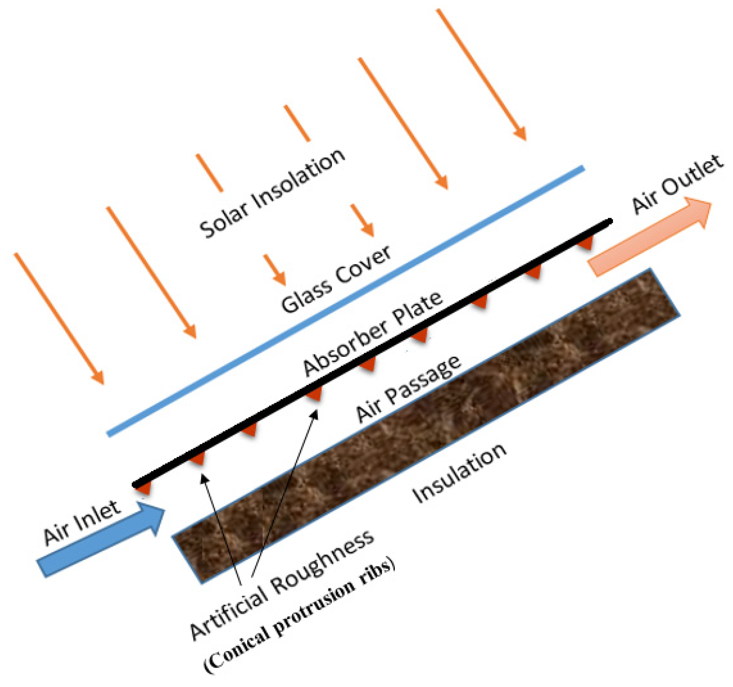
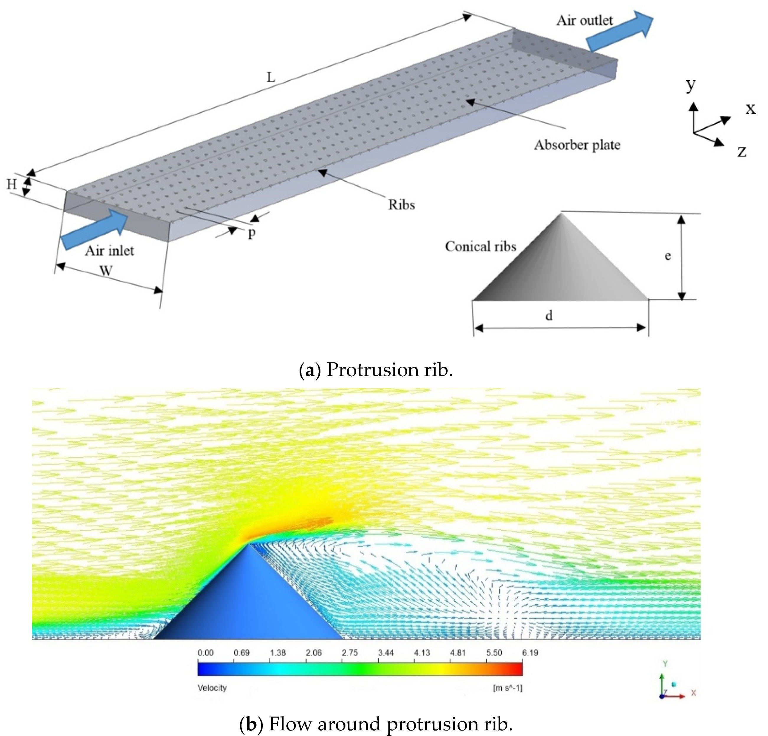
2. Conical Protrusion-Roughened SAH

An SAH is a well-known solar thermal system which is utilized to heat the air by absorbing the available insolation. The performance of an SAH depends on the intensity of insolation, the concentration ratio of the collector, the heat transfer capability of the absorber plate to air, the absorptivity and emissivity of the absorber plate and measures taken to keep the heat losses at a minimum, especially from the top glass cover. An SAH consists of a flat absorber plate parallel to the air flow passage where air is to be heated. In order to eliminate the heat loss from the absorber, a glass cover is employed to minimize the top heat losses, and insulation is employed to eliminate the back and side heat losses. The absorber absorbs solar insolation when it is struck through the glass cover and heats the flowing air in the passage, as shown in Figure 1.
When aiming to design the optimum collector, temperature variation, convective heat transfer coefficient and friction factor for an absorber, the heat removal factor and useful heat gain play a dominant role in understanding the heat extraction rate from the absorber to air. Previously, a surface with conical protrusion rib roughness (Figure 2a) has been analyzed to predict the heat transfer coefficient, friction factor and thermal efficiency. Higher heat transfer due to the sharp apex corner of the conical protrusion ribs has been attributed to high turbulence with a strong re-attachment point in the vicinity of the rib, which helps to disturb the sub-laminar layer, as presented in Figure 2b [28].
The energy conservation for various principal components of an SAH—i.e., the glass cover, absorber plate and air—have been discussed and attributed to the evaluation of the net effective efficiency. The following assumptions have been made during the analysis; (i) the thermo-physical properties of the glass cover, absorber plate and air remain equal; (ii) there is no effect of climatic parameters such as humidity and climatic variation; and (iii) there is no effect caused by the sun’s location and the location of interest (latitude and longitude). A simplified thermal network of an SAH (presented in Figure 1) is shown in Figure 3, in which the thermal resistance is evaluated on the basis of convective and radiative heat transfer coefficients between the absorber plate and air, the absorber plate and the glass cover and the glass cover and the sky. The absorber plate absorbs solar insolation and distributes this into useful heat gain to the air; however, top heat loss, bottom heat loss and side-edge heat loss are also present.
Heat exchange between the absorber and glass cover:
q l o s s , p c = h c , c p ( T p T c 1 ) + σ ( T p 4 T c 4 ) 1 ε p + 1 ε c 1 = ( h c , p c + h r , p c ) ( T p T c )
where
h r , p c = σ ( T p 2 + T c 2 ) ( T p + T ) 1 ε p + 1 ε c 1
R 2 = 1 ( h c , c p + h r , c p )
The convective heat transfer between the absorber and cover is calculated as given below:
h c , p c = N u k L
where
N u = 1 + 1.44 [ 1 1708 / R a C o s β t i ] + { 1 1708 ( s i n 1.8 β t i ) 1.6 / R a C o s β t i } + [ ( R a C o s β t i / 5830 ) 0.33 1 ]
R a = g β ( T p T c ) L 3 ν α
The radiation resistance from the top cover is calculated to account for the radiation exchange with the sky at temperature, Ts, the radiation heat transfer coefficient is given below:
h r , c a = σ ε c ( T c + T s ) ( T c 2 + T s 2 ) ( T c T s ) ( T c T a )
R 1 = 1 ( h r , c a + h w )
The resistance to the surroundings and the top loss coefficient from the collector to ambient air is calculated as
U t = 1 ( R 1 + R 2 )
The edge loss coefficient and back heat loss coefficient are calculated as
U e = 1 ( R 4 ) = ( U A ) e d g e A p   and   U b = 1 ( R 3 ) = K i n s t i
The useful heat gain to fluid is as follows:
Q u = [ I ( τ α ) U o ( T p T a ) ] A p
where the overall heat loss coefficient is
U o = U t + U b + U e
where (τα) is the transmittance–absorptance product of the absorber.
The thermal efficiency of the collector is
η t h = Q u A p I
Furthermore, the thermo-hydraulic efficiency in terms of the net effective efficiency [30] is calculated as given below:
The net effective efficiency of the collector is
η n e t = Q u P m C A p I
where C (=0.18) is the conversion factor of the thermal energy converted from mechanical power.
Pm is the mechanical power needed to drive the fan/blower to cause the air to flow at a predetermined level, given as
P m = m ( Δ P ) d ρ a
The pressure drop (ΔP)d can be evaluated by determine the friction factor value, which is given below:
( Δ P ) d = 2 f ρ L V 2 D h

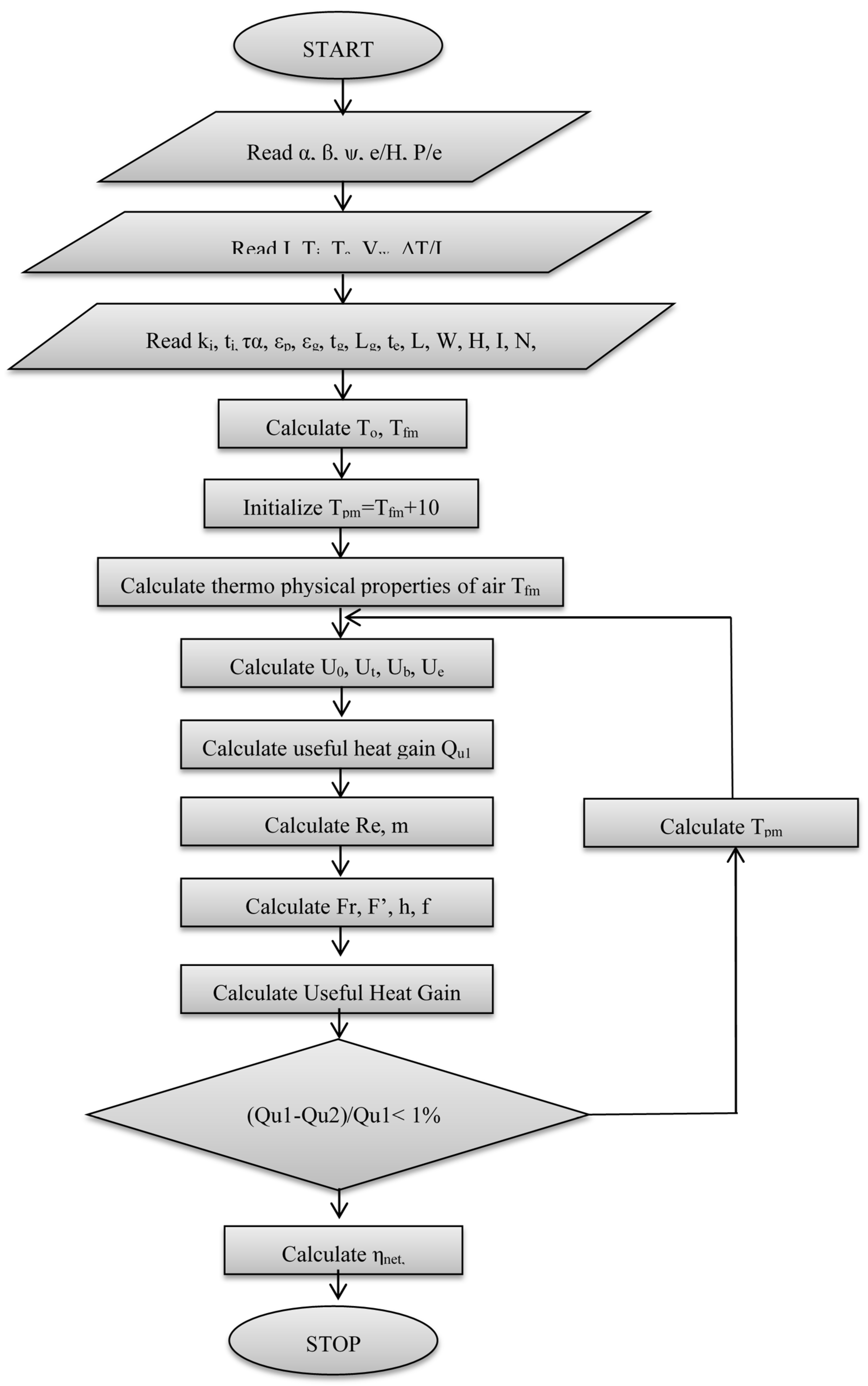
3. Steps to Calculate the Thermo-Hydraulic Performance

Characteristics of the thermo-hydraulic performance (net effective efficiency) of the conical protrusion rib roughened surface of an SAH have been evaluated under similar operating conditions to those available in the literature [25]. The rib parameters were selected from the authors’ previous study [28]. All systems, ribs and operating parameters are listed in Table 1.
In order to evaluate the net effective efficiency of the conical protrusion rib roughened surface in an SAH, it was compared with a smooth-duct SAH. However, the convective heat transfer coefficient and friction factor of the conical protrusion rib roughened surface were exploited and evaluated with regard to their respective correlations. The rib parameters of the conical protrusion rib roughened surface were exploited to predict the thermo-hydraulic performance. The steps taken in the procedures are given below:
  • The rib parameters—i.e., the relative rib pitch and relative rib height—were identified in the entire study for which the characteristic of the net effective efficiency needed to be evaluated. System parameters of the SAH and operating parameters such as the solar insolation, inlet air temperature, ambient temperature, sky temperature, mass flow rate and wind speed needed to be kept fixed;
  • The outlet temperature of air was determined using insolation and temperature increase parameters, while the inlet air temperature was considered as ambient temperature:
    T o = ( Δ T I ) I + T i
Then, the thermo-physical properties of air were considered as a function of temperature and evaluated based on the mean temperature of air;
3.
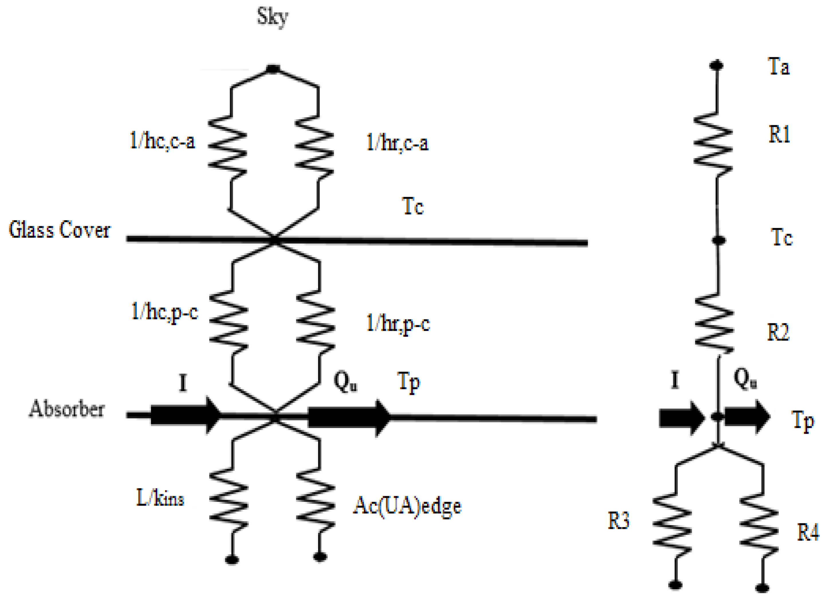
The overall heat loss coefficient was the sum of the back cover heat loss coefficient, side-edge heat loss coefficient and top heat loss coefficient, which were evaluated in the following manner:
U o = U t + U b + U e
The top heat loss coefficient was determined by the proposed correlation of Akhtar and Mullick [31]:
1 U t = [ σ ( T p m 2 + T g 2 ) ( T p m + T g ) ( 1 ε p + 1 ε g 1 ) + ( k a N u 1 L g ) ] 1 + [ σ ε g ( T g 2 + T a 2 ) ( T g + T a ) + h w ] 1 + t g k g
The mean plate temperature was approximated as 10 °C above the mean air temperature. The back cover heat loss coefficient and side edge heat loss coefficient were evaluated in the following manner:
U b = k i t i ,   U e = ( L + W ) t e k i L W t i
where
F 1 = [ 12 × 10 8 ( T a + 0.2 T p ) 3 + h w ] 1 + 0.3 t g [ 6 × 10 8 ( ε p + 0.028 ) ( T p m + 0.5 T a ) 3 + 0.6 L g 0.2 { ( T p m T a ) C o s β t i } 0.25 ] 1
T g = ( F 1 T p m + c T a 1 + F 1 )
T s = 0.0522 ( T a ) 1.5
c = [ ( T s / T a ) + ( h w / 3.5 ) 1 + h w + 3.5 ]
N u = 1 + 1.44 [ 1 1708 / R a C o s β t i ] + { 1 1708 ( s i n 1.8 β t i ) 1.6 / R a C o s β t i } + [ ( R a C o s β t i / 5830 ) 0.33 1 ]
R a = G r P r
and
G r = g · β · ( T p m T g ) · L g 3 υ 2
4.
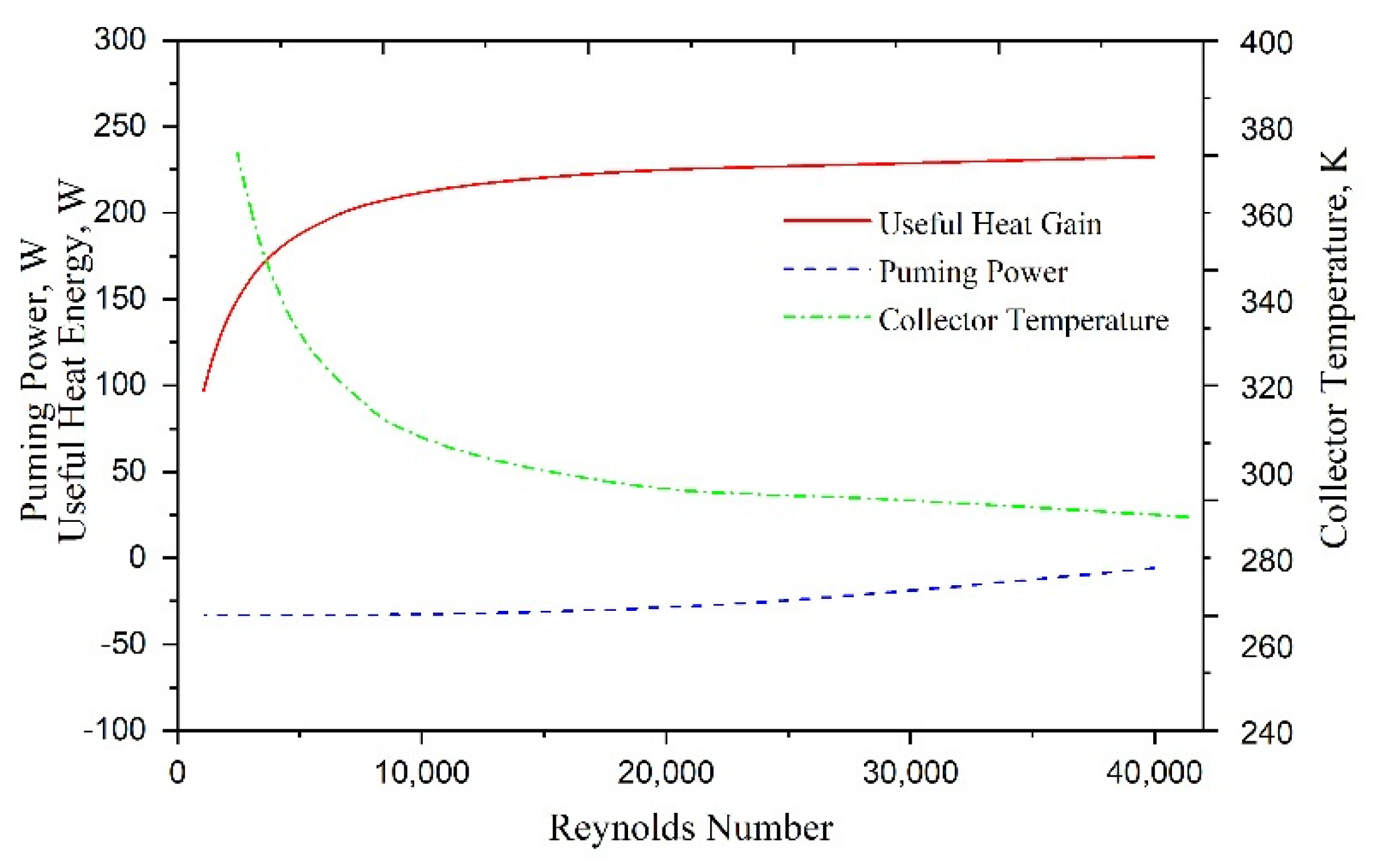
Useful heat gain was estimated by determining the overall heat loss coefficient. Then, the Reynolds number of air was evaluated in the following manner:
Q u 1 = [ I ( τ α ) U o ( T p m T a ) ] A P ,   m = Q u 1 C p Δ T ,   R e = m D h μ ( W H )
5.
The Nusselt number was estimated by the correlation of the conical protrusion rib roughness in the air passage [28]; then, the convective heat transfer of the absorber plate was estimated as follows:
N u = 2.29 × 10 4 R e 0.984 ( e / D ) 0.280 ( p / e ) 4.085 e [ 0.922 { ln ( p / e ) } 2 ]
( Δ P d ) = 2 f L ρ V 2 D h
h = N u . k D h
6.
Again, the heat gain by air was determined by estimating the heat removal factor and collector fin efficiency as follows [32]:
Q u 2 = A p F [ I ( τ α ) U l ( T o T a ) ]
where
F o = m C P A P U l [ e x p { F A P U l m C P } 1 ] ,   F = h h + U o
7.
Qu1 and Qu2 were compared; if these values deviated from each other, the new value of Tpm was determined using the value of heat gain, Qu2, from Equation (17). Iterations continued until the values of Qu1 and Qu2 became nearly equal ( i . e . ,   Q u 1 Q u 2 Q u 1 < 1 % ) :
T p m = T a + [ I ( τ α ) Q u 2 / A p U l ]
8.
The friction factor was estimated by the correlation of the conical protrusion rib roughness [28]. Then, the pressure drop and mechanical power needed to propel the air through SAH were calculated:
f = 2.19 × 10 4 R e 0.352 ( e / D ) 5.839 e [ 0.739 { ln ( e / D ) } 2 ] ( p / e ) 1.860 e [ 0.523 { ln ( p / e ) } 2 ]
where ,   P m = m ( Δ P ) d ρ   and   ( Δ P d ) = 2 f L ρ V 2 D h
Finally, the net effective efficiency was estimated for the conical protrusion rib roughened SAH by Equation (9). The process was performed for different sets of rib and operating parameters. The flow chart of this methodology is presented in Figure 4.

4. Result and Discussion

The net effective efficiency of the conical protrusion rib roughened surface of an SAH was evaluated according to methodology discussed in the previous section. The distribution of the net effective efficiency showed that an indirect comparison of useful heat gain to air and the pumping power of air could be made for various conical protrusion rib parameters as a function of the Reynolds number and temperature increase parameter. Prior to starting the discussion on net effective efficiency, the behavior of the useful heat gain, absorber temperature and pumping power need to be understood; therefore, the respective plots of useful heat gain, pumping power requirements and mean collector temperature are presented as a function of the Reynolds number for an e/D of 0.0289, p/e of 10 and I of 1000 W/m2, as shown in Figure 5.
It can be seen from the plots that the mean temperature of the absorber plate decreased with the Reynolds number and became nearly constant. Contrary to this, the heat gain increased with the Reynolds number and became nearly flat for a high Reynolds number, implying that a lower plate temperature exhibited low heat loss through the glass cover and resulted in a high heat extraction rate by air from the absorber. On the other hand, the pumping power increased slightly with the Reynolds number, but the increment rate was not significant.

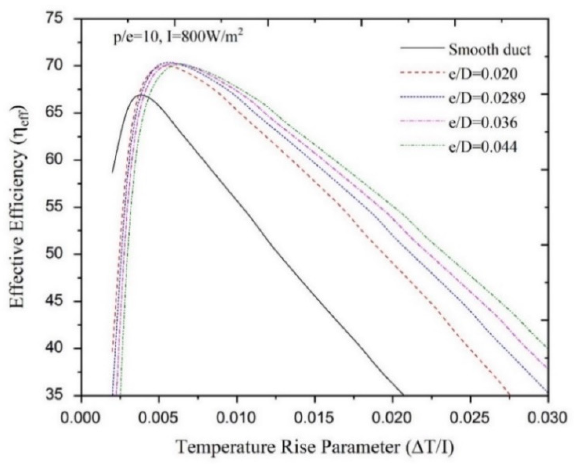
4.1. Effect of Relative Height

The net effective efficiency of the conical protrusion rib roughened absorber of an SAH was evaluated for all possible combinations of relative rib heights and relative pitches with 600 W/m2, 800 W/m2 and 1000 W/m2 of insolation. The net effective efficiency of a smooth SAH was also evaluated for comparison purposes. In Figure 6, the net effective efficiencies are plotted for fixed conical rib parameters (e/D = 0.0289, P/e = 10) at 800 W/m2 of insolation. It is observed from the plots that the net effective efficiencies increased with increases in the temperature increase parameter and then decreased continuously for all relative rib heights. However, the peaks of net effective efficiency were observed at different temperature increase parameters depending on the relative rib height. The range of temperature parameters at which a higher net-effective efficiency was observed is listed in Table 2. It is observed that a smooth SAH offered the best net effective efficiency when the temperature increase parameter was less than 0.00369 K·m2/W. The relative rib height parameter was dominant as the temperature rise parameter increased. Different relative rib heights of 0.020, 0.0289 and 0.036 exhibited the best net effective efficiency in the following ranges of temperature rise parameters: 0.00369 < ΔT/I < 0.00463 K·m2/W, 0.00463 < ΔT/I < 0.00608 K·m2/W and 0.00608 < ΔT/I < 0.00691 K·m2/W. A relative rib height of 0.044 exhibited the best net effective efficiency at a temperature increase parameter of more than 0.0069 K·m2/W. Figure 7 shows the variation of the net effective efficiencies with Reynolds number for fixed conical rib parameters (P/e = 10) at 800 W/m2 of insolation. It can be seen from the plots that net effective efficiencies increased with increases in the Reynolds number, reached a peak and then decreased continuously with increases in the Reynolds number. The peak of the net-effective efficiency was observed at different Reynolds number values depending on the relative rib height. Similarly, for maximum net effective efficiency, the ranges of the Reynolds number for different relative rib heights are listed in Table 2. The SAH without roughness (smooth duct) exhibited the best net effective efficiency with a value of the Reynolds number of more than 21,640. At a Reynolds number below 21,640, the conical protrusion rib roughness exhibited the best efficiency. Relative rib heights of 0.020, 0.0289 and 0.036 exhibited the best net effective efficiency in the following ranges of Reynolds numbers: 16,812 < Re < 21,640, 12,253 < ΔT/I < 16,812 and 11,095 < ΔT/I < 12,253. At a Reynolds number below 11,095, a relative height of 0.044 offered the best net-effective efficiency. The enhancement factors of net effective efficiency due to the conical protrusion rib roughness surface are listed in Table 3 for different relative rib heights.

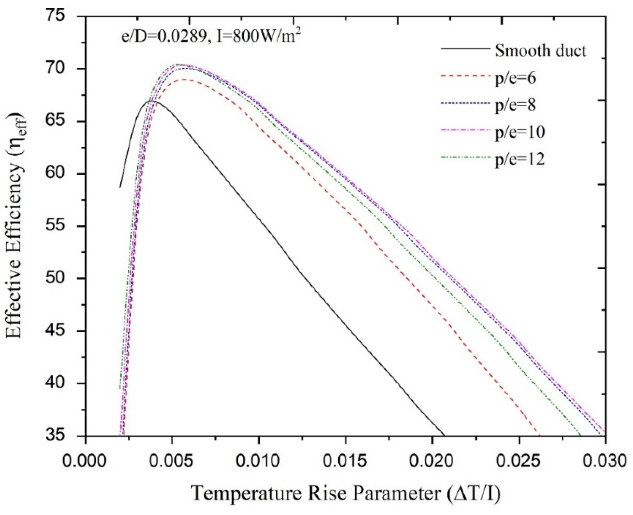
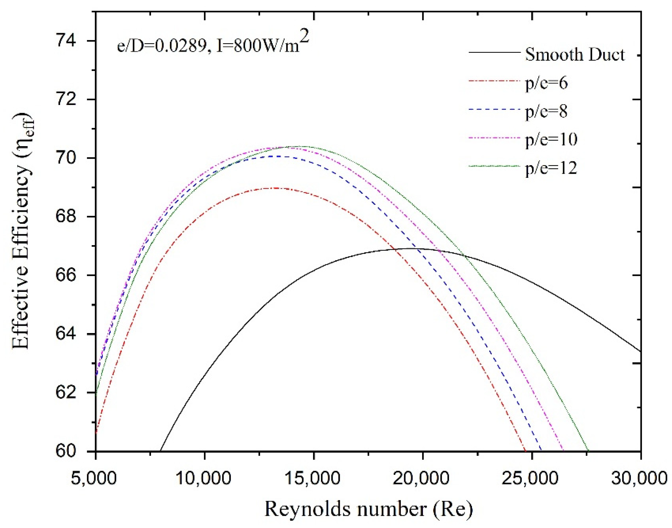
4.2. Effect of Relative Pitch

Similarly, the net effective efficiency of conical protrusion rib roughnesses for different relative pitches are plotted with temperature increase parameters at 800 W/m2 of insolation, as shown in Figure 8. It is observed from the plots that the net effective efficiencies at different relative pitches increased with increases in the temperature increase parameter, reached a peak and then decreased with further increases in the temperature increase parameter. The peak of the net effective efficiency was observed at different temperature increase parameters depending on the relative rib pitch. The range of temperature parameters in which a higher net-effective efficiency was observed for a particular relative rib pitch are listed in Table 4. It can be seen that a smooth SAH offered the best net effective efficiency when the temperature increase parameters were less than 0.00365 K·m2/W. The relative rib height parameter was dominant when the temperature increase parameter increased beyond 0.00365 K·m2/W. A relative rib pitch of 12 exhibited the best net effective efficiency in the range of temperature increase parameters of 0.00365 < ∆T/I < 0.00562 K·m2/W. A relative rib pitch of 10 exhibited the best net. effective efficiency when the temperature increase parameter was more than 0.00562 K·m2/W. Figure 9 shows the variation of net effective efficiencies with Reynolds numbers for a fixed relative rib height (e/D = 0.00289) at 800 W/m2 of insolation. It is observed that the net-effective efficiencies increased with an increase in the Reynolds number, reached a peak and then decreased continuously with increase in Reynolds number. The peak of net-effective efficiency has been observed at different Reynolds number values depending on the relative rib height. Similarly, for maximum net effective efficiency, the ranges of Reynolds numbers for different relative rib heights are listed in Table 4. A relative rib pitch of 10 of the conical protrusion rib exhibited the best net effective efficiency with a Reynolds number less than 13,520. A relative rib pitch of 10 exhibited the best net effective efficiency when the SAH operated at the range of Reynolds numbers of 13,520 < Re < 21,780. Beyond a Reynolds number of 21,780, the SAH duct without roughness (smooth duct) offered the best net effective efficiency in comparison to protrusion rib roughness in the SAH. Additionally, it can be seen from the plots that pitches of 6 and 8 did not contribute to a significant performance change. Enhancement factors for the net effective efficiency due to the conical protrusion rib roughness surface are also listed in Table 5 at different relative pitches.

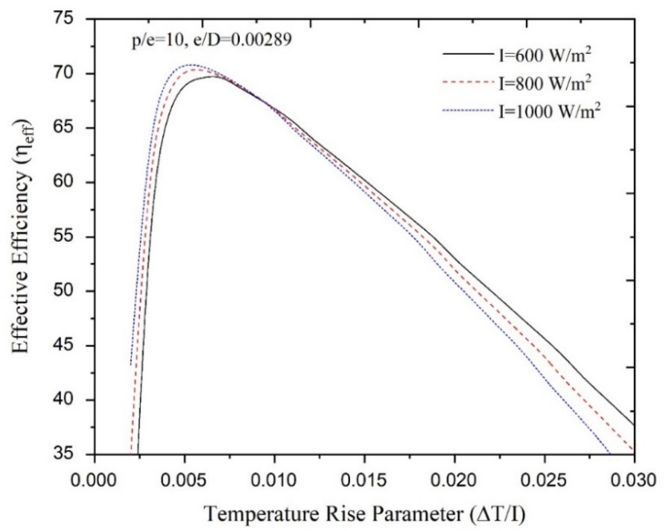
4.3. Effect of Solar Insolation

In order to show the effect of solar insolation, the net effective efficiency of the conical protrusion rib roughness in the SAH was also evaluated for various kinds of solar insolation. Figure 10 shows the plots of net effective efficiency for a fixed roughness parameter (p/e = 10, e/D = 0.0289) at different insolations of 600 W/m2, 800 W/m2 and 1000 W/m2. Similar plots are observed to those discussed in the previous sub-section. The peaks of the plots of net effective efficiency were found for different temperature increase parameters. The net effective efficiency rose with increases in the temperature increase parameter; thereafter, it decreased with further increases in the temperature increase parameter. Suddenly, the net effective efficiency began to decrease, indicating that there is large pumping power requirement. The rate of the decrement in net effective efficiency at 1000 W/m2 was higher compared to the net effective efficiencies at 600 W/m2 and 800 W/m2. This is due to the fact that a higher plate temperature is achieved due to higher insolation, leading to high top heat loss and consequently lower net effective efficiency.
The results of the net effective efficiency due to conical protrusion rib roughness have been compared with the results for a semi-spherical dimpled rib roughness [23] and semi-spherical protrusion rib roughness [27] available in the literature. In Figure 11, the maximum net effective efficiencies of semi-spherical dimpled rib and semi-spherical protrusion rib roughness are plotted corresponding to their rib parameters (parameters of semi-spherical dimple rib p/e = 10, e/D 0.036 and α = 60° and parameter of semi-spherical protrusion rib p/e = 12, e/D 0.030 and α = 60°). The trend of the net effective efficiency of the conical protrusion rib roughness is similar to that of the trend of the semi-spherical protrusion rib roughness and semi-spherical dimpled rib roughness. The net effective efficiency with a conical protrusion rib roughness was greater than the net effective efficiency with a semi-spherical protrusion rib roughness at a low Reynolds number. Thereafter, the net effective efficiency with a semi-spherical protrusion rib was dominant and surpassed the net effective efficiency of the conical protrusion rib roughness. This occurs due to the dominance of the higher friction factor of the conical protrusion rib roughness, which leads to a large pumping power requirement. The sharp corners of conical ribs contribute to higher turbulence in comparison to the semi-spherical protrusion rib. As an effect of the large pumping power requirement, the net effective efficiency of the conical protrusion rib roughness decreases sharply below the net effective efficiency of the semi-spherical protrusion rib roughness at higher Reynolds numbers.

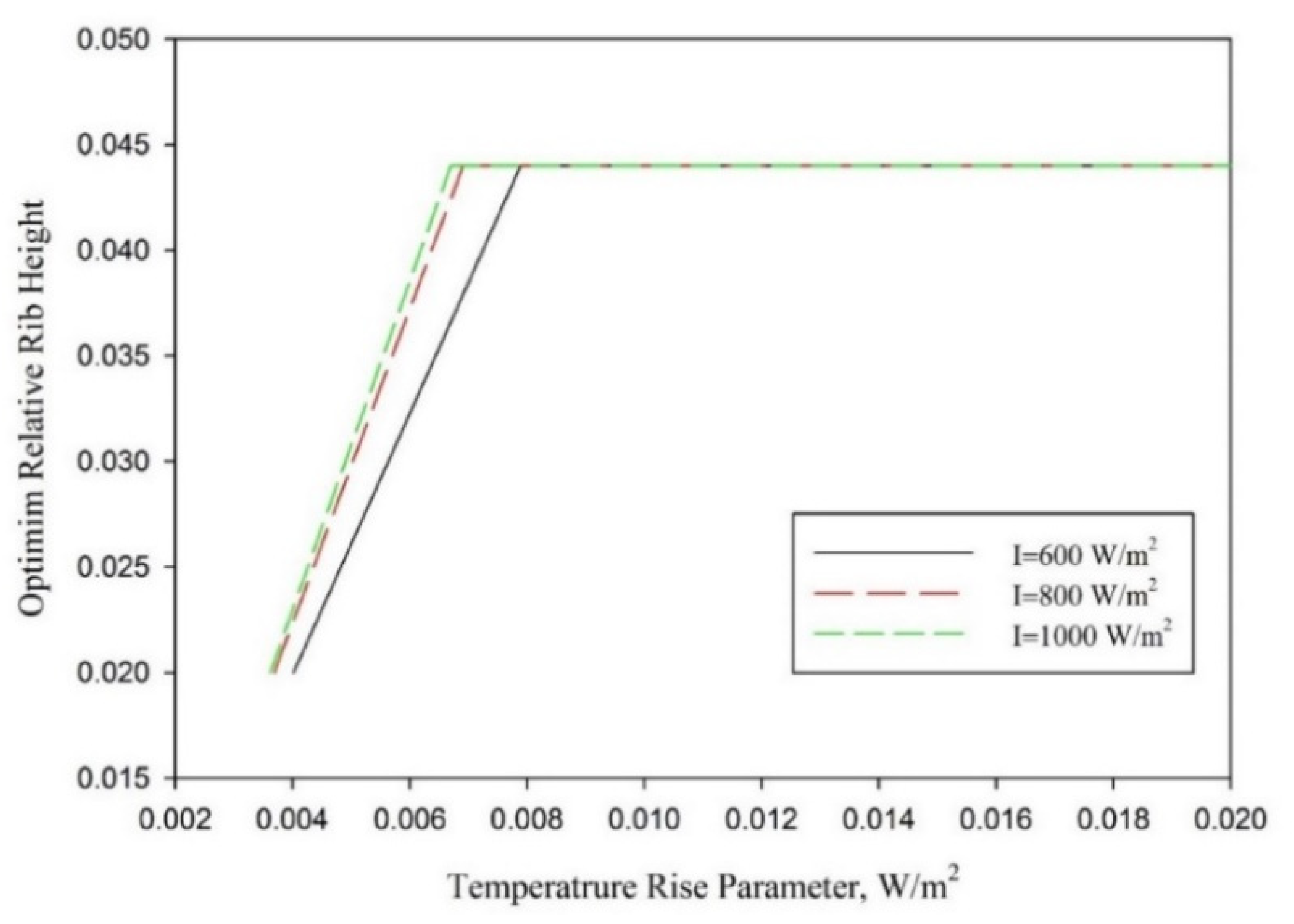
5. Optimization of Conical Protrusion Roughness Parameters

Ranges of temperature increase parameters for various optimum rib parameters corresponding to the maximum net-effective efficiency have also been computed for insolations in the range of 600 W/m2 to 1000 W/m2. Optimum values of the relative rib height of the conical protrusion rib roughness for various insolations (600, 800 and 1000 W/m2) are presented in Figure 12. It was observed that a relative rib height of 0.044 was found to be optimum when the temperature increase parameter was more than 0.00789 K·m2/W for all insolations, while a smooth duct yielded the best effective efficiency when the temperature increase parameter was less than 0.00362 W/m2.K for all insolations. Furthermore, the optimum relative rib height of conical protrusion ribs was a function of insolation when the temperature increase parameter was in the following range: 0.00362 K·m2/W < ΔT/I < 0.00789 K·m2/W.
Similarly, values of the optimum relative rib pitch for various temperature increase parameters are presented in Figure 13 for all insolations. It can be seen clearly that the smooth duct offered the highest effective efficiency over the conical protrusion rib roughness with all possible combination of rib parameters for all insolations when the temperature rise parameter was less than 0.00355 K·m2/W. However, a relative rib height of 10 offered the best effective efficiency when the temperature increase parameter was more than 0.00602 K·m2/W.
The optimum rib parameters can be determined from Figure 12 and Figure 13 for given insolation and temperature rise parameters. Furthermore, the unique optimum combination of rib parameters was found when ∆T/I > 0.00789 K·m2/W, and this optimum combination comprised a relative pitch ratio of 10 and relative rib height of 0.044 for all values of insolation.

6. Conclusions

An analytical study has been conducted to predict the characteristics of the net effective efficiency of a conical protrusion rib-roughened absorber surface in an SAH. In order to evaluate the enhancement factor, the net effective efficiency of a roughened absorber has also been compared to the net effective efficiency of a smooth absorber operating under similar conditions. On the basis of the results obtained, the conical protrusion rib parameters have been optimized for maximum net effective efficiency. Key findings of this study are given below.
  • A conical protrusion rib roughness significantly affects the net effective efficiency of an SAH duct. An effective efficiency increase of up to 70.92% was obtained at an e/D of 0.0289 and p/e of 10;
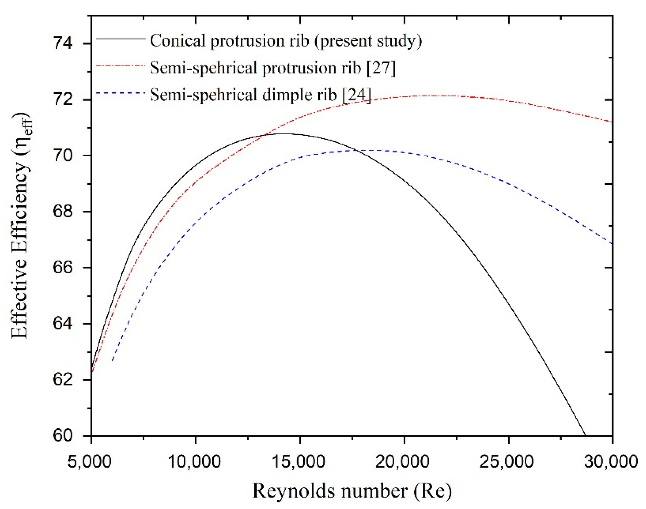
  • Net effective efficiency is observed to depend strongly on the Reynolds number: a higher Reynolds number always results in a relatively low value of effective efficiency irrespective of roughness parameters because of the very high frictional power requirements. Furthermore, in the lower Reynolds number range, the actual value of rib parameter determines the value of the effective efficiency;
  • Net effective efficiency is also observed to be a function of insolation. The maximum effective efficiency increased from 69.82% to 70.92% when the insolation increased from 600 W/m2 to 1000 W/m2;
  • A set optimum values of conical protrusion rib parameters exists that corresponds to specified operating conditions, resulting in maximum effective efficiency. The optimum relative rib heights have been found to be 0.020, 0.0289, 0.036 and 0.044 for temperature increase parameter ranges of 0.00369 < ∆T/I <0.00463 K·m2/W, 0.00463 < ∆T/I 0.00608 K·m2/W, 0.00608 < ∆T/I 0.00691 K·m2/W and 0.00691 < ∆T/I K·m2/W, respectively. Similarly, ranges of temperature increase parameters of 0.00365 < ∆T/I < 0.00562 K·m2/W and 0.00365 < ∆T/I K·m2/W have been found in which relative rib pitches of 12 and 10, respectively, exhibit the best net effective efficiency;
  • Optimum values of the relative rib pitch and relative rib height vary with the temperature increase parameter, and ranges of the temperature increase parameter for optimum roughness parameters change slightly with insolation;
  • A unique combination of an optimum relative rib height of 0.44 and relative rib pitch of 10 are observed regardless of the insolation value when ∆T/I > 0.00789 K·m2/W.
Thermo-hydraulic performance analysis has been carried out to arrive at the optimum values of conical rib protrusion rib parameters that result in maximum net useful gain for the given operating conditions. The characteristics of net effective efficiency will help designers to determine conical protrusion rib parameters under different operating conditions.

Author Contributions

Conceptualization, T.A.; methodology, T.A; software, T.A.; validation, T.A.; formal analysis, T.A and N.B.B.; investigation, T.A., C.S.M. and N.B.B.; resources, T.A., C.S.M., N.B.B. and R.C.; data curation, T.A.; writing—original draft preparation, T.A.; writing—review and editing, C.S.M., N.B.B., A.K. and R.C.; visualization, C.S.M.; supervision, T.A. and A.K.; funding acquisition, R.C. All authors have read and agreed to the published version of the manuscript.

Funding

This research received no external funding.

Data Availability Statement

The data are not publicly available due to privacy considerations.

Conflicts of Interest

The authors declare no conflict of interest.

Disclosure

The article is published with the permission of the Director, CSIR-Central Building Research Institute, Roorkee.

Nomenclature

βtiTilt angle, °
βCoef of thermal expansion of air, 1/K
εgEmissivity of glass cover
εpEmissivity of absorber plate
ηthThermal efficiency
ηnetNet effective efficiency
ρDensity of air, kg/m3
σStefan–Boltzmann Constant, W/m2.K4
τTrasnmissivity of glass cover
µDynamic viscosity of air, Kg/m·s
υKinematic viscosity of air, m2/s
(τα)Transmittance-absorbent product of glass cover
ApArea of absorber plate, m2
CpSpecific heat of air at constant pressure, J/Kg.K
DDuct height, mm
eRib height, mm
e/DRelative rib height
F′Flat efficiency factor,
FoHeat removal factor
fFriction factor of roughened duct
fsFriction factor of smooth duct
hHeat transfer coefficient, W/m2.K
hrRadiative heat transfer coefficient, W/m2.K
hcConvective heat transfer coefficient, W/m2.K
hwWind convective heat transfer coeff., W/m2.K
GrGrashoff number,
ISolar insolation, W/m2
LgAir gap b/w absorber plate and glass cover, m
kaThermal conductivity of air, W/m/K
kgThermal conductivity of glass, W/m/K
mMass flow rate, Kg/s
NNumber of glass cover
NuNusselt number of roughened duct
NusNusselt number of smooth duct
PPitch of ribs, mm
PmPumping power, W
P/eRelative pitch ratio
PrPrandtl number
QuUseful heat gain, J
RThermal Resistance, K/W
RaRayleigh number
ReReynolds number
TaAmbient temperature, K
TiInlet temperature, K
ToOutlet temperature of air, K
TpmAverage plate mean temperature, K
TsSun temperature, K
ΔTAir temperature rise, K
ΔT/ITemperature rise parameter, K.m2/W
tiThickness of insulation, mm
tgThickness of glass cover, mm
tgHeight of collector edge, mm
UbBack heat loss coefficient, W/m2.K
UeEdge heat loss coefficient, W/m2.K
UtTop heat loss coefficient, W/m2.K
VAir velocity, m/s
VwWind speed, m/s

References

  1. Statistical Review of World Energy, 68th Edition. 2019. Available online: www.bp.com (accessed on 21 May 2021).
  2. Sukhatme, S.P. Solar Energy: Principles of Thermal Collection and Storage, 9th ed.; Tata McGraw-Hill: New Delhi, India, 2003. [Google Scholar]
  3. Duffie, J.A.; Beckman, W.A. Solar Engineering Thermal Processes; John Wiley: Hoboken, NJ, USA, 1991. [Google Scholar]
  4. Alam, T.; Kim, M.H. A critical review on artificial roughness provided in rectangular solar air heater duct. Renew. Sustain. Energy Rev. 2017, 69, 387–400. [Google Scholar] [CrossRef]
  5. Prasad, B.N.; Saini, J.S. Optimal thermohydraulic performance of artficially roughened solar air heaters. Solar Energy 1991, 47, 91–96. [Google Scholar] [CrossRef]
  6. Prasad, B.; Saini, J. Effect of artificial roughness on heat transfer and friction factor in a solar air heater. Sol. Energy 1988, 41, 555–560. [Google Scholar] [CrossRef]
  7. Gupta, D.; Solanki, S.; Saini, J. Heat and fluid flow in rectangular solar air heater ducts having transverse rib roughness on absorber plates. Sol. Energy 1993, 51, 31–37. [Google Scholar] [CrossRef]
  8. Momin, A.-M.E.; Saini, J.; Solanki, S. Heat transfer and friction in solar air heater duct with V-shaped rib roughness on absorber plate. Int. J. Heat Mass Transf. 2002, 45, 3383–3396. [Google Scholar] [CrossRef]
  9. Hans, V.; Saini, R.; Saini, J. Heat transfer and friction factor correlations for a solar air heater duct roughened artificially with multiple v-ribs. Sol. Energy 2010, 84, 898–911. [Google Scholar] [CrossRef]
  10. Aharwal, K.; Gandhi, B.; Saini, J. Experimental investigation on heat-transfer enhancement due to a gap in an inclined continuous rib arrangement in a rectangular duct of solar air heater. Renew. Energy 2008, 33, 585–596. [Google Scholar] [CrossRef]
  11. Kumar, A.; Saini, R.; Saini, J. Experimental investigation on heat transfer and fluid flow characteristics of air flow in a rectangular duct with Multi v-shaped rib with gap roughness on the heated plate. Sol. Energy 2012, 86, 1733–1749. [Google Scholar] [CrossRef]
  12. Gawande, V.B.; Dhoble, A.; Zodpe, D.; Chamoli, S. Experimental and CFD investigation of convection heat transfer in solar air heater with reverse L-shaped ribs. Sol. Energy 2016, 131, 275–295. [Google Scholar] [CrossRef]
  13. Kumar, R.; Goel, V.; Singh, P.; Saxena, A.; Kashyap, A.S.; Rai, A. Performance evaluation and optimization of solar assisted air heater with discrete multiple arc shaped ribs. J. Energy Storage 2019, 26, 100978. [Google Scholar] [CrossRef]
  14. Wang, D.; Liu, J.; Liu, Y.; Wang, Y.; Li, B.; Liu, J. Evaluation of the performance of an improved solar air heater with “S” shaped ribs with gap. Sol. Energy 2020, 195, 89–101. [Google Scholar]
  15. Jaurker, A.; Saini, J.; Gandhi, B. Heat transfer and friction characteristics of rectangular solar air heater duct using rib-grooved artificial roughness. Sol. Energy 2006, 80, 895–907. [Google Scholar] [CrossRef]
  16. Juarker, A.R. Heat and Fluid Flow Characteristics of Rib-Groove Artificially Roughened Solar Air Heater; Indian Institute of Technology: Roorkee, India, 2005. [Google Scholar]
  17. Layek, A.; Saini, J.; Solanki, S. Effect of chamfering on heat transfer and friction characteristics of solar air heater having absorber plate roughened with compound turbulators. Renew. Energy 2009, 34, 1292–1298. [Google Scholar] [CrossRef]
  18. Layek, A.; Saini, J.; Solanki, S. Heat transfer and friction characteristics for artificially roughened ducts with compound turbulators. Int. J. Heat Mass Transf. 2007, 50, 4845–4854. [Google Scholar] [CrossRef]
  19. Alam, T.; Saini, R.; Saini, J. Effect of circularity of perforation holes in V-shaped blockages on heat transfer and friction characteristics of rectangular solar air heater duct. Energy Convers. Manag. 2014, 86, 952–963. [Google Scholar] [CrossRef]
  20. Chamoli, S. Preference selection index approach for optimization of V down perforated baffled roughened rectangular channel. Energy 2015, 93, 1418–1425. [Google Scholar] [CrossRef]
  21. Alam, T.; Saini, R.; Saini, J. Heat transfer enhancement due to V-shaped perforated blocks in a solar air heater duct. Appl. Mech. Mater. 2014, 619, 125–129. [Google Scholar] [CrossRef]
  22. Saini, R.; Verma, J. Heat transfer and friction factor correlations for a duct having dimple-shape artificial roughness for solar air heaters. Energy 2008, 33, 1277–1287. [Google Scholar] [CrossRef]
  23. Sethi, M.; Varun; Thakur, N. Correlations for solar air heater duct with dimpled shape roughness elements on absorber plate. Sol. Energy 2012, 86, 2852–2861. [Google Scholar] [CrossRef]
  24. Sethi, M.; Thakur, N.S.; Varun. Heat transfer and friction characteristics of dimple-shaped roughness element arranged in angular fashion (arc) on the absorber plate of solar air heater. J. Renew. Sustain. Energy 2012, 4, 023112. [Google Scholar] [CrossRef]
  25. Bhushan, B.; Singh, R. Nusselt number and friction factor correlations for solar air heater duct having artificially roughened absorber plate. Sol. Energy 2011, 85, 1109–1118. [Google Scholar] [CrossRef]
  26. Perwez, A.; Kumar, R. Thermal performance investigation of the flat and spherical dimple absorber plate solar air heaters. Sol. Energy 2019, 193, 309–323. [Google Scholar] [CrossRef]
  27. Yadav, S.; Kaushal, M.; Varun. Siddhartha Nusselt number and friction factor correlations for solar air heater duct having protrusions as roughness elements on absorber plate. Exp. Therm. Fluid Sci. 2013, 44, 34–41. [Google Scholar] [CrossRef]
  28. Alam, T.; Kim, M.-H. Heat transfer enhancement in solar air heater duct with conical protrusion roughness ribs. Appl. Therm. Eng. 2017, 126, 458–469. [Google Scholar] [CrossRef]
  29. Sharma, S.K.; Kalamkar, V. Thermo-hydraulic performance analysis of solar air heaters having artificial roughness—A review. Renew. Sustain. Energy Rev. 2015, 41, 413–435. [Google Scholar] [CrossRef]
  30. Cortés, A.; Piacentini, R. Improvement of the efficiency of a bare solar collector by means of turbulence promoters. Appl. Energy 1990, 36, 253–261. [Google Scholar] [CrossRef]
  31. Akhtar, N.; Mullick, S. Approximate method for computation of glass cover temperature and top heat-loss coefficient of solar collectors with single glazing. Sol. Energy 1999, 66, 349–354. [Google Scholar] [CrossRef]
  32. Duffie, J.A.; Beckman, W.A.; Worek, W.M. Solar Engineering of Thermal Processes, 2nd ed.; Wiley: New York, NY, USA, 1980. [Google Scholar]
Figure 1. Schematic diagram of an SAH.
Energies 14 03159 g001
Figure 2. Conical protrusion rib roughness [28].
Energies 14 03159 g002
Figure 3. Thermal resistance of an SAH.
Energies 14 03159 g003
Figure 4. Flow chart.
Energies 14 03159 g004
Figure 5. Variation of absorber temperature, heat gain and pumping power.
Energies 14 03159 g005
Figure 6. Effect of temperature increase parameter on effective efficiency.
Energies 14 03159 g006
Figure 7. Effect of Reynolds number on effective efficiency.
Energies 14 03159 g007
Figure 8. Effect of temperature increase parameter on effective efficiency.
Energies 14 03159 g008
Figure 9. Effect of Reynolds number on effective efficiency.
Energies 14 03159 g009
Figure 10. Effect of solar insolation on net effective efficiency.
Energies 14 03159 g010
Figure 11. Comparison of net effective efficiency with similar roughnesses.
Energies 14 03159 g011
Figure 12. Optimum value of relative rib height.
Energies 14 03159 g012
Figure 13. Optimum value of relative rib pitch.
Energies 14 03159 g013
Table 1. Values/ranges of parameters.
ParameterValue
System Parameters
Tilt angle (βti)30°
Emissivity of absorber plate (εp)0.9
Emissivity of transparent glass cover (εg)0.88
Transmittance–absorptance product0.8
Thickness of collector edge (te)0.1 m
Thickness of glass cover (tg)0.002 m
Thickness of back insulation (ti)0.05 m
Thermal conductivity of insulation (ki)0.037 W/m⋅K
Collector length (L)1.0 m
Gap between collector and glass cover (Lg)0.025 m
Collector duct height (H)0.025 m
Number of glass covers (N)1
Collector width (W)0.3 m
Relative rib height (e/D)0.020–0.044
Relative rib pitch (p/e)6–12
Operating parameters
Ambient temperature (Ta)285 K
Wind velocity (Vw)1.0 m/s
Temperature rise parameter (ΔT/I)0.002–0.030 K⋅m2/W
Insolation (I)600 W/m2–1000 W/m2
Table 2. Ranges of temperature increase parameters and Reynolds numbers.
I = 800 W/m2 and p/e = 10
Roughness ParameterOptimized Value of ParameterRanges of Temperature Increase Parameters (ΔT/I)Ranges of Reynolds Numbers (Re)
Relative rib height (e/D)SmoothT/I < 0.0036921,640 < Re
e/D = 0.0200.00369 < ∆T/I < 0.0046316,812 < Re < 21,640
e/D = 0.02890.00463 < ∆T/I 0.0060812,253 < Re < 16,812
e/D = 0.0360.00608 < ∆T/I 0.0069116,812 < Re < 21,640
e/D = 0.0440.00691 < ∆T/IRe < 11,095
Table 3. Enhancement in effective efficiency at different relative rib heights.
P/e = 10, I = 800 W/m2e/D = 0.020e/D = 0.0289e/D = 0.036e/D = 0.044
Enhancement factor in effective efficiency (ηeffeffs),ΔT/I = 0.0051.0641.0691.0611.049
ΔT/I = 0.0101.1721.1991.2091.217
ΔT/I = 0.0151.2671.3101.3331.353
ΔT/I = 0.0201.3531.4321.4861.52
ΔT/I = 0.0251.4131.5591.6291.69
ΔT/I = 0.0301.4371.6771.7971.900
Table 4. Ranges of temperature increase parameters and Reynolds numbers.
I = 800 W/m2 and e/D = 0.0289
Roughness ParameterOptimized Value of ParameterRanges of Temperature Increase Parameters (ΔT/I)Ranges of Reynolds Numbers (Re)
Relative rib pitch (p/e)SmoothT/I < 0.0036521,780 < Re
p/e = 120.00365 < ∆T/I < 0.0056213,520 < Re < 21,780
p/e = 10<∆T/I 0.00562Re < 13,520
Table 5. Enhancement factor for effective efficiency at different relative rib pitches.
e/D = 0.0289, I = 800 W/m2p/e = 6p/e = 8p/e = 10p/e = 12
Enhancement factor in effective efficiency (ηeffeffs),ΔT/I = 0.0051.0461.0631.0691.072
ΔT/I = 0.0101.1571.1971.1991.189
ΔT/I = 0.0151.2411.3061.311.286
ΔT/I = 0.0201.3081.4251.4321.388
ΔT/I = 0.0251.3351.5481.5591.471
ΔT/I = 0.0301.291.6411.6771.533
Publisher’s Note: MDPI stays neutral with regard to jurisdictional claims in published maps and institutional affiliations.

