1. Introduction
An electricity power network consists of basic elements of generation, transmission, distribution and users or consumers. Large power plants are scheduled based on the projected power needs for each day, and world auctions are held to achieve the best price and reliability outcome for the consumer. Due to an increasing trend of using more ecological electricity sources such as solar systems [
1,
2], wind farms [
3,
4], etc., much greater demands are placed on the transmission network in terms of its structure [
5,
6], stability [
7], optimization [
8,
9,
10] and securing the requirements of the end customer against interference [
11,
12,
13].
Each large power company has a control center that works to keep the generated and used power in balance through their existing and diverse communication networks. In addition, they use other communication networks to keep track of the conditions of the control electronics in the substations to respond in case of faults or equipment failures. All these networks with electronic information and communication systems are vulnerable to the effects of HPEM environments.
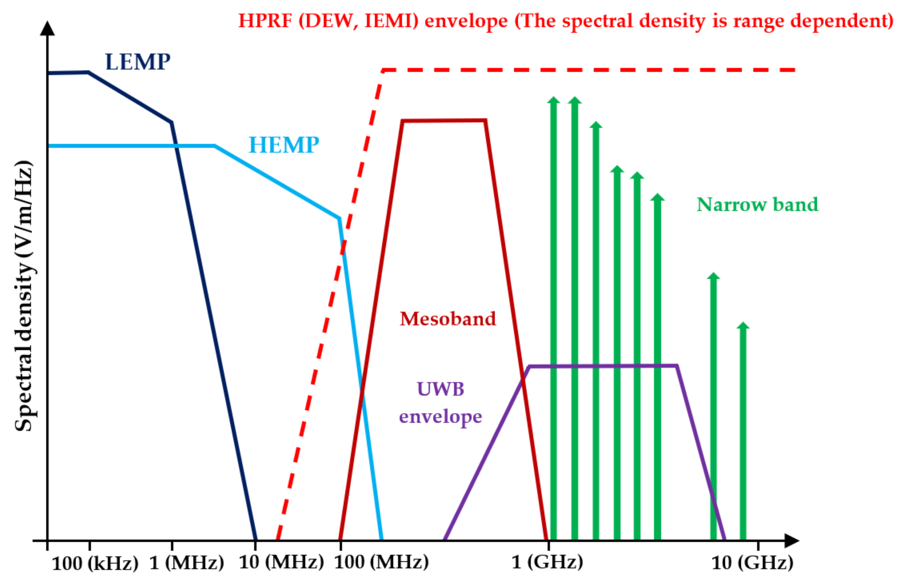
HPEM environments include lightning electromagnetic pulse (LEMP), extreme geomagnetic storm impacts, nuclear electromagnetic pulse (NEMP), high-altitude electromagnetic pulse (HEMP) and high-power radio frequency (HPRF) phenomena, including directed energy weapons (DEWs) and intentional electromagnetic interference (IEMI). In the field of security, the used term is DEW; in civilian terminology, the used term is directed energy (DE). In particular, DEWs and IEMIs are currently a major threat to the functioning of electronic and information systems in electricity power networks, as well as in other state infrastructures [
14,
15].
DEWs and IEMIs create a pulsed power electromagnetic field called electromagnetic pulse (EMP), which can cause the malfunctioning or even destruction of electronic circuits. Due to fast research development in this area, small compact devices can be built. These devices are very attractive for use in defense and security technology, but they can also be misused by terrorists. The specific use of DEWs and IEMIs depends on the method of generating electromagnetic fields and also on the used frequency band. DEWs and IEMIs usually work in the following modes:
A single pulse with many cycles of a single frequency (an intense narrowband signal that may have some frequency agility);
A burst containing many pulses, with each pulse containing many cycles of a single frequency;
An ultra-wide-band (UWB) transient pulse (spectral content from 100 s of MHz to several GHz);
A burst of many radiated or conducted UWB pulses.
DEW and IEMI signals can penetrate radiation or conduction in electronic devices [
16,
17].
Figure 1 shows the frequency bands of individual components of HPEM environments. The figure was taken from [
14]. Spectral density is plotted on the vertical axis. The unit is V/m/Hz.
In DEW and IEMI environments, it is crucial to consider the dependence of the E-field on the distance of the DEW or IEMI generator from the target. The parameter often used in this area is rE; in other publications, also referred to as factor of merit (FOM), the unit is volts (V). This parameter represents the product of E-field E and distance r from the transmitting generator antenna.
DEW and IEMI generators, suitable for use in intentionally disrupting the function of technology containing sensitive electronics, can be divided according to the level of their complexity and thus their availability as follows [
16,
18,
19,
20,
21,
22]:
Low-tech generators rE ≃ 1 kV (e.g., microwave oven);
Medium-tech generators rE ≃ tens to hundreds of kV (e.g., modified radars transmitters);
High-tech generators rE ≃ order of units MV (special technologies).
The E-field level at the location of the electronic device (target) in the relevant frequency band is decisive for the disruption or destruction of the electronic systems. Disruption of activities or destruction of the target can be achieved by high-tech or medium-tech generators operating from a long distance or by a low-tech generator positioned close to the target. Currently, a very attractive location for DEW and IEMI generators is onboard unmanned aerial vehicles (UAVs). Project CHAMP [
23,
24] shows results of DEW or IEMI generators onboard a UAV causing high-efficiency disruption or destruction of electronic systems.
The following sections deal with the design and testing of a low-tech DEW generator, which was used for the purpose of determining the electromagnetic immunity of standard electronic circuits. A magnetron was used as the power element of the generator. Subsequently, measurements of electromagnetic immunity of electronic circuits are performed without additional protection against the effects of E-field. The result is the determination of the E-field limits for fault-free operation and for fault states of the tested circuits and the E-field level for irreversible destruction of the circuits.
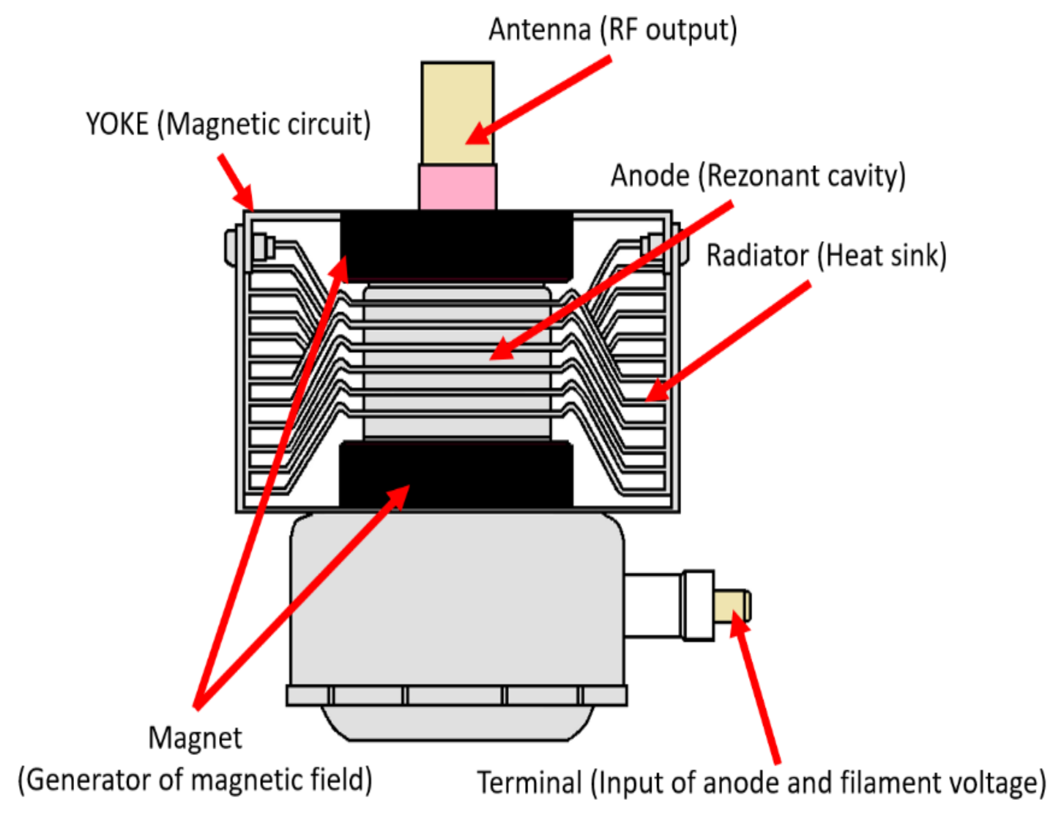
2. Concept of a Low-Tech DEW Generator with a Magnetron
A magnetron, commonly used in microwave ovens, was selected to produce a microwave power generator operating in the S-band (
Figure 2).
A magnetron was used in the microwave power generator as a source of high-frequency oscillations with high power (Type 2M219J). This magnetron is commonly used in microwave ovens as a source of electromagnetic energy.
Table 1 shows the magnetron specification from the manufacturer catalog sheet.
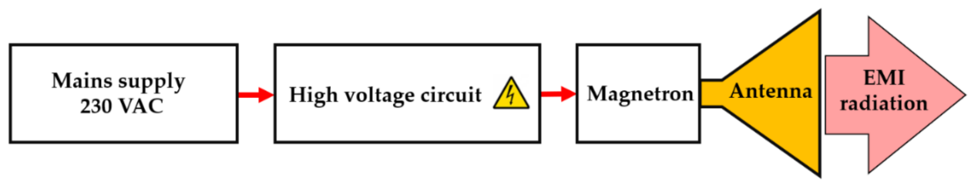
2.1. Basic Connection of Microwave Power Generator
The fundamental principle of generator operation can be described according to the following block diagram (
Figure 3). The microwave power generator is powered separately from the 230 VAC distribution network. This power supply is powered by an AC/DC step-up converter with a high-voltage transformer (MOT), the output of which is 4.2 kVDC to power the magnetron. Using a funnel antenna, the electromagnetic energy is radiated into the space in the desired direction.
This circuit had an overall efficiency of around 55%, and additional effort was made to change and optimize the overall concept of the power microwave generator in order to increase the overall efficiency of the microwave generator.
2.2. Optimization of the Microwave Power Generator
In order to achieve continuous operation of the generator, it was important to design a new concept of the entire connection. In addition, it was mandatory to address operator safety when designing a new generator concept to prevent accidental electric shock.
While testing the magnetron in terms of use for our application, cooling showed to be a challenge to be solved. In addition, overheating the magnetron significantly reduced its efficiency. Therefore, modification of the entire generator concept had to be put in place.
Figure 4 shows the heated magnetron after 90 s at full power.
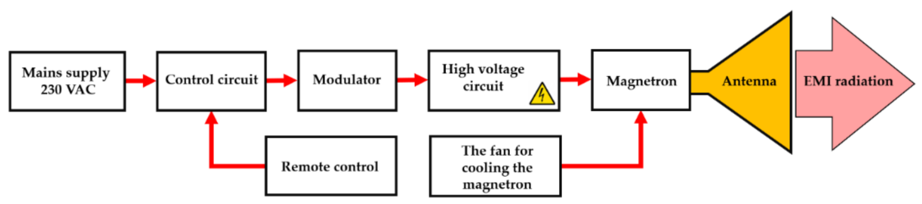
When designing a functional microwave power generator, it was important to arrange the various parts (components) so that they did not interfere with each other, not only in terms of EMI, but also primarily in terms of temperature (
Figure 5).
2.3. Description of the Optimized Microwave Power Generator
The power supply of the generator is from the industrial network 230 VAC/50 Hz.
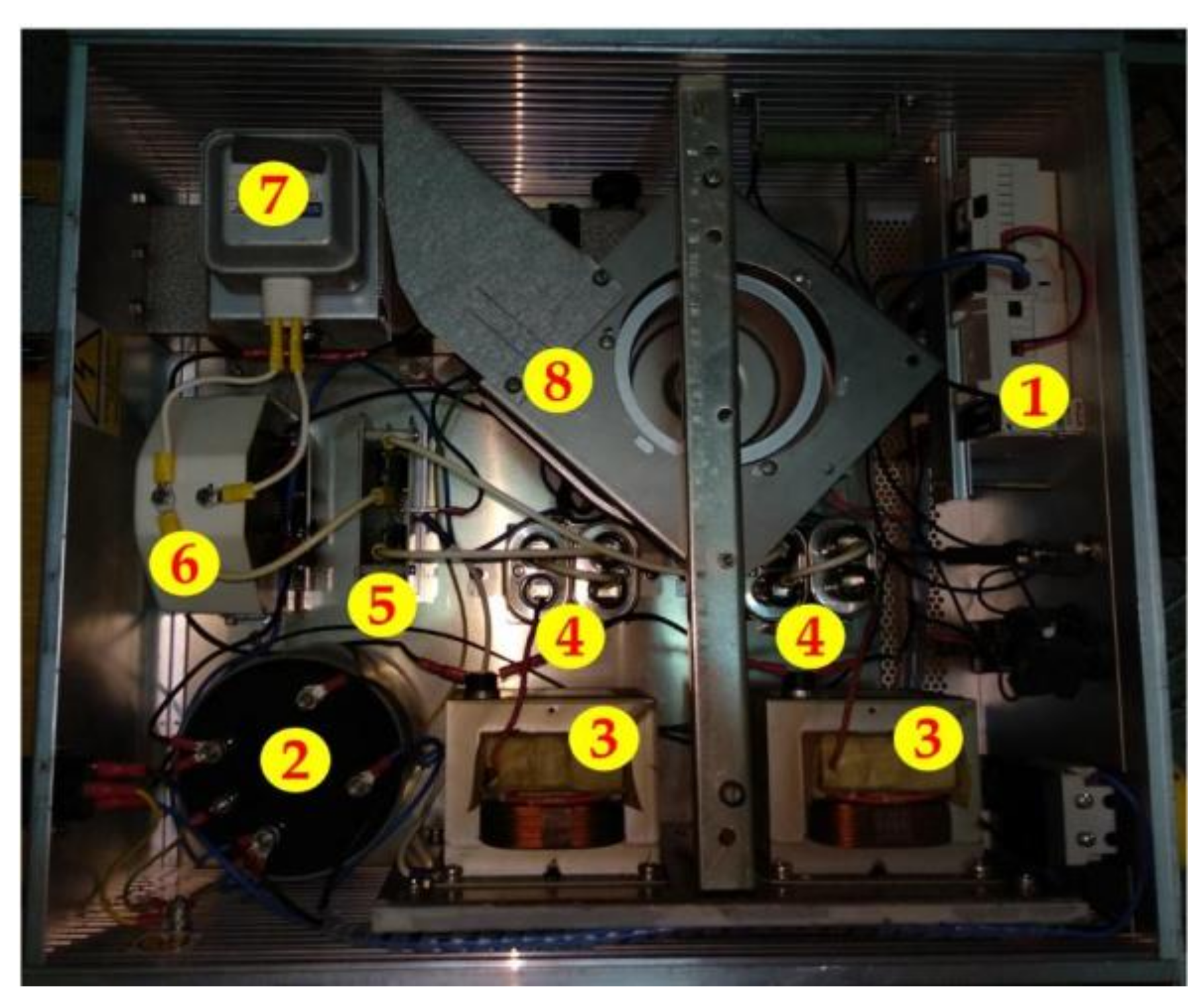
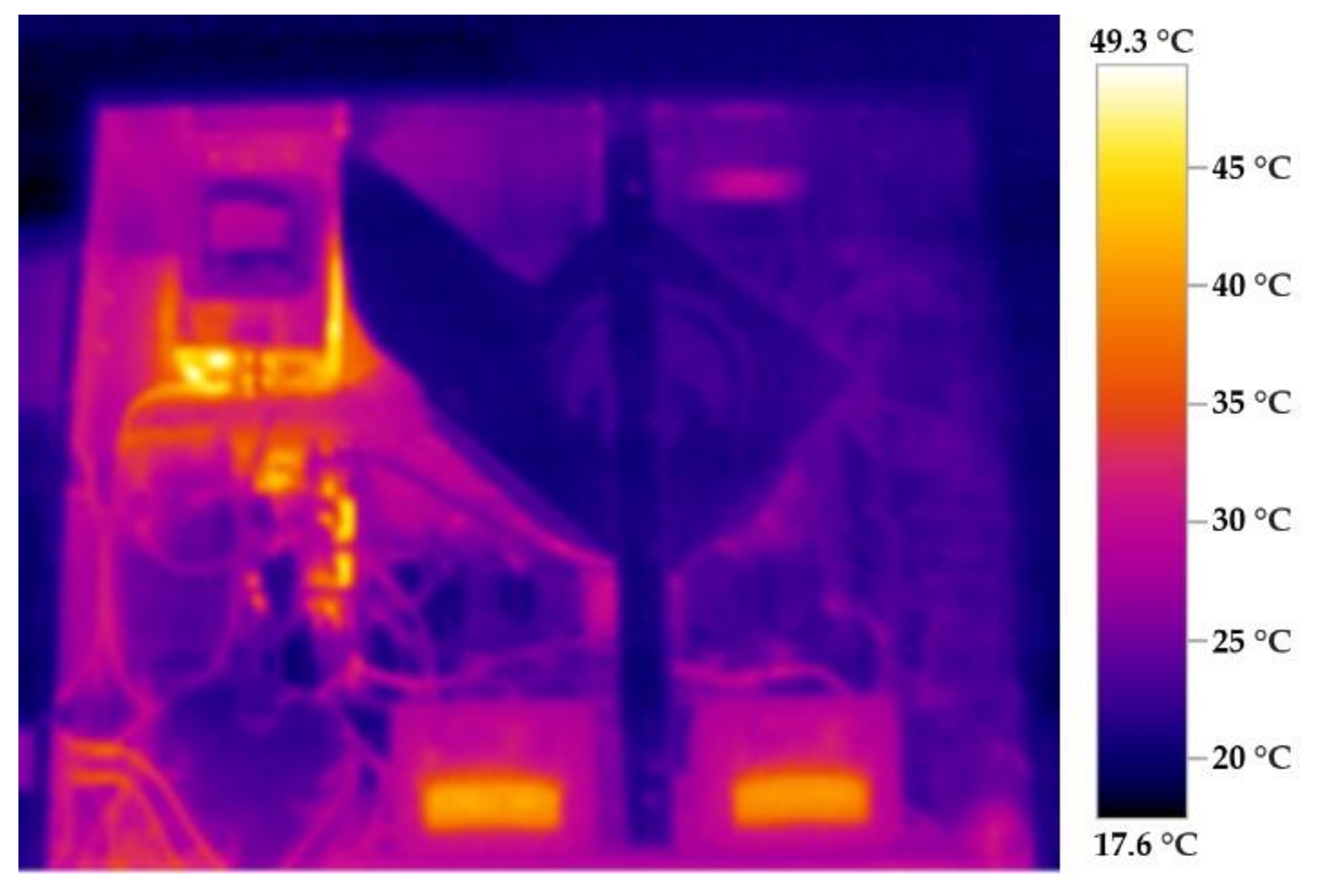
Figure 6 shows the internal arrangement of the generator after the design modifications. Number (1) indicates the generator safety and control elements. When the fuses and controls are switched on, voltage is applied to the isolating transformer (2), which supplies two high-voltage transformers (3), whose output voltage 2 × 2.1 kVAC is connected to the high-voltage rectifier (5) via high-voltage capacitors 2 × 50 µF (4). It is routed to the magnetron (7) via a high-voltage isolating transformer (6). The magnetron is cooled by a specially designed fan (8), where the air is flown directly to the fins of the magnetron’s cooling system via a ventilator. This magnetron cooling solution ensures a continuous operation of the entire generator. In addition, the generator is equipped with a safety device that will turn off the generator in case of overheating. This safety device consists of thermal sensors (thermal fuses), which are attached to the thermally stressed elements of the generator.
All the components of the microwave power generator are arranged in a way to minimize their own influence on the EMI. However, the most important aspect was the placement of the components during the design in such a way that they did not interfere with each other in terms of temperature. The most thermally loaded component is the magnetron and the power transformers (MOT). It is clear from the picture that they are at a sufficient distance from each other.
Figure 7 shows a thermal diagram of all the individual components of the optimized microwave power generator after 10 min of full power. All the temperature measurements were performed using a thermal camera from Testo [
25].
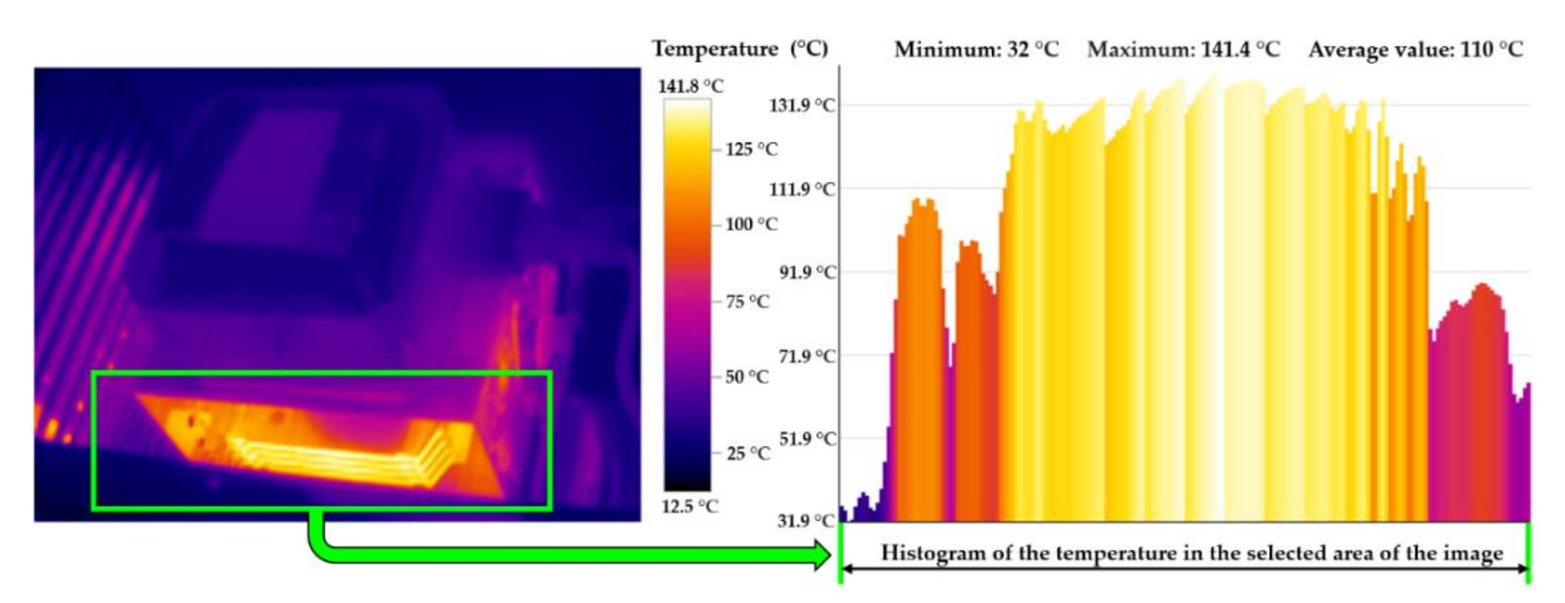
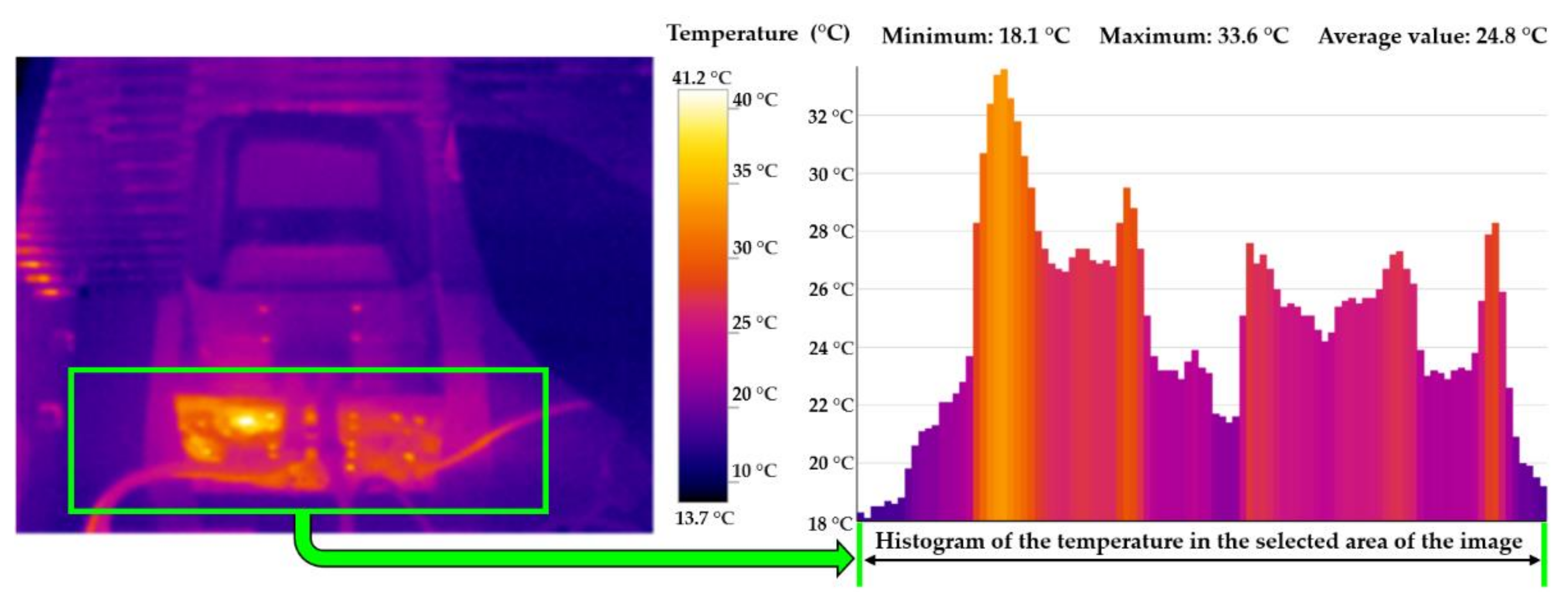
By using the improved cooling design, we were able to achieve continuous microwave power generator operation without changing the parameters of the magnetron (change in frequency and efficiency due to high temperature). This means that the magnetron had a constant temperature of up to 50 °C (
Figure 8). This ensured the stability of the entire system. In addition, the new arrangement increased the power microwave generator efficiency from 55 to 75%.
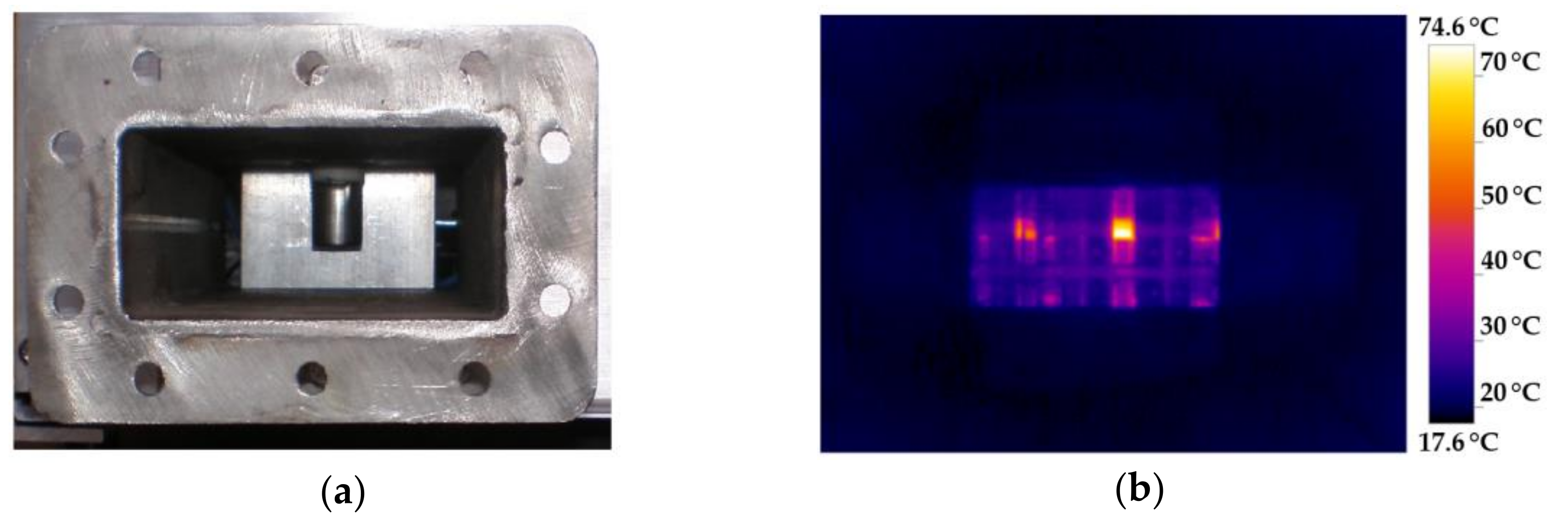
Figure 9a shows a standardized R32 waveguide, in which an opening for the magnetron antenna was made.
Figure 9b shows the temperature inside the waveguide after 10 min of full power. Thanks to the proposed cooling, this temperature did not rise above 80 °C. Due to the fact that the magnetron is firmly connected to the waveguide, the temperature was highest at this point as only a part of the waveguide was cooled, without the magnetron antenna being cooled directly. However, this temperature did not affect the function and parameters of the power microwave generator (
Table 2).
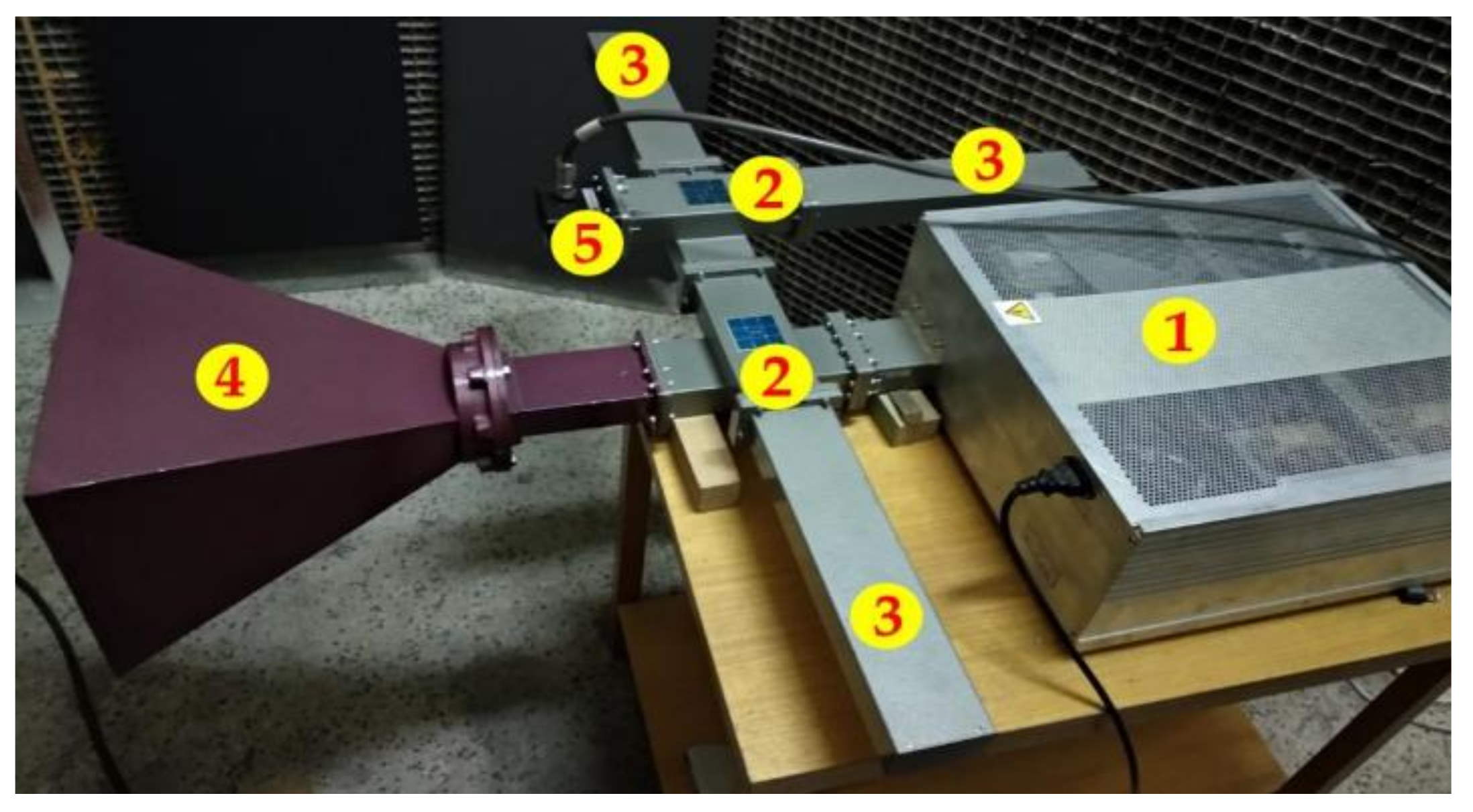
Figure 10 shows a microwave power generator with a standardized R32 waveguide and the necessary components for analyzing the transmitted signal, including the antenna. Number (1) indicates an EMI microwave power generator with a magnetron, and Number (2) is a waveguide tap. The branch is a crossed waveguide, in which through-cavities are formed in such a way that in the forward direction of the transmission the electromagnetic wave is without attenuation, and in the cross direction the attenuation is according to the size of the cavity. Two identical waveguide taps with 30 dB attenuation [
26,
27,
28,
29] were connected to the waveguide route. However, it was important to consider how much power there was at the 30 dB tap. If the power was still too high, it was necessary to connect an additional power attenuator that would reduce the power sufficiently and protect the measuring instruments. Attached to these waveguide taps are waveguide matched loads, which are marked as Number (3). These were intended to adapt the waveguide path in the given direction. Furthermore, an antenna is connected, which is marked as Number (4). The antenna assured the transmission of the electromagnetic wave into the space in the required direction. The last part of the assembly is a waveguide coupling (5) for a coaxial cable. Due to this coupling, we can connect various types of measuring instruments (oscilloscope, spectrum analyzer, power meter, etc.).
3. Testing Electronic Circuits’ Immunity to EMP
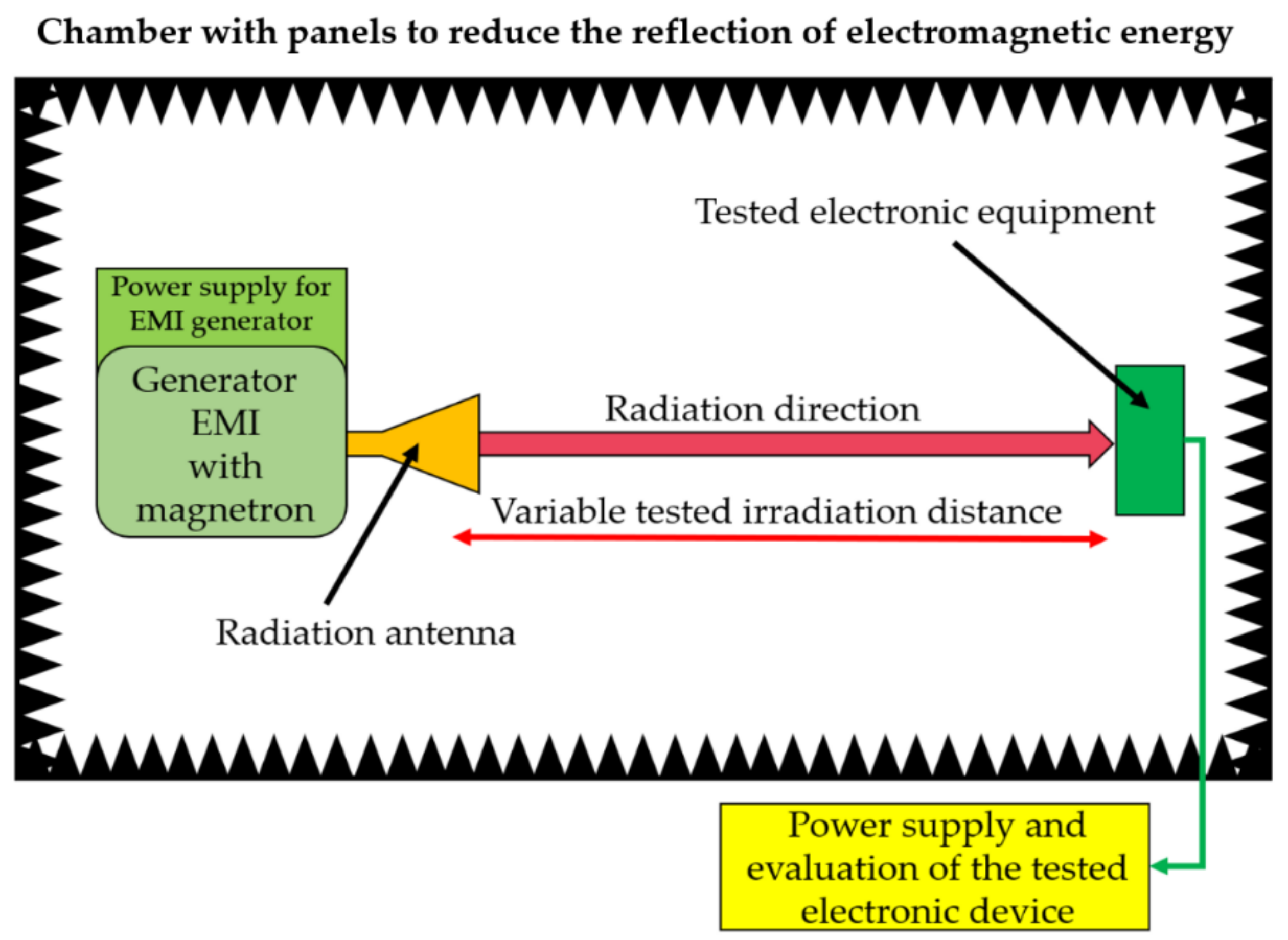
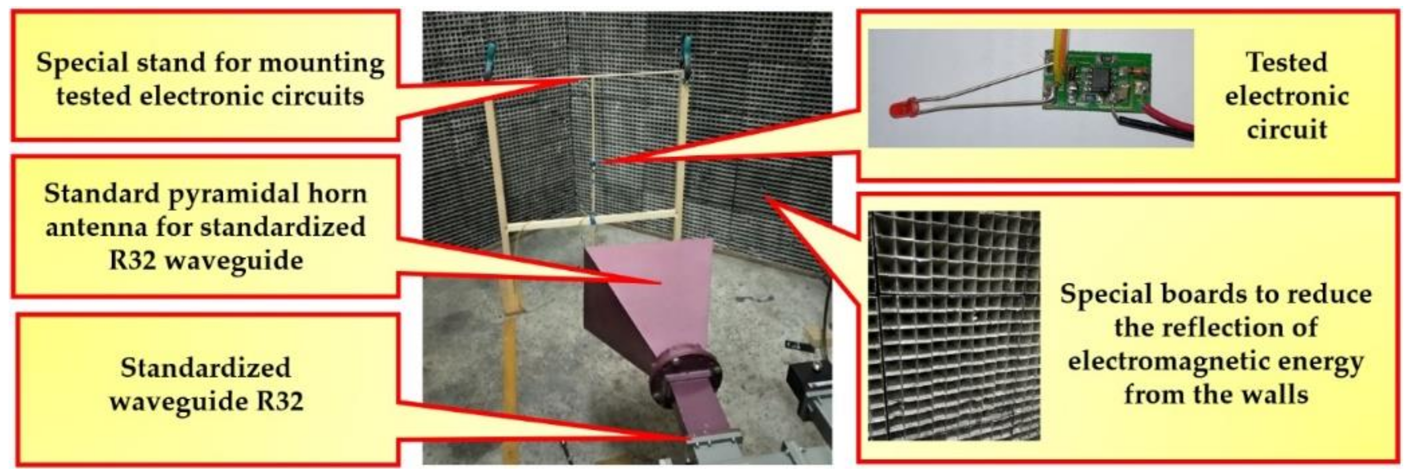
A special test site for testing electronic circuits in an electromagnetic field (EMP) was set up in a laboratory designated for testing electronic devices in the EMP (
Figure 11). This lab has special plates on the walls to reduce the reflection of the electromagnetic energy from the walls (
Figure 12).
The tested electronic circuit was placed on a special stand in the axis of the radiation pattern of the generator antenna. The stand was gradually moved towards the antenna of the generator. Testing was performed for the antenna distances from 1.1 to 0.25 m. For each position, the tested electronic circuit was irradiated by the generator for 2 s. The E-field created by the generator was measured for each position. At the same time, operation of the tested electronic circuit was verified at each position. A sleeve dipole antenna (
Figure 13a) with an attenuator was used as a sensor for the E-field measurement to adjust the measured power level. An R&S RTO 1044-4GHz-20 GSa/s with an oscilloscope (
Figure 13b) was used to measure the signal levels.
The NE555P (the NE555P is an integrated circuit most commonly used as a timer or generator of various rectangular signals) integrated circuit was chosen to power our genuine design of a semiconductor power microwave generator. A rectangular pulse generator was assembled with this integrated circuit, in which a potentiometer was used to change the frequency. To visually examine correct functionality of the integrated circuit (IC), this circuit was equipped with a light-emitting diode (LED). The battery-powered NE555P test circuit was exposed to EMP at various distances.
The measured E-field levels were compared to the E-field distribution created on the basis of a simplified theory of electromagnetic wave radiation. The calculation of the parameters for a pyramidal horn antenna of the E-field generator was performed by Equations (1) and (2).
where:
E—
E-field (V/m);
Pdensity—power density (W/m2);
Z0—the impedance of free space (Ω).
where:
R—the distance between the test circuit and the antenna (m);
Pg—the power of the microwave generator (W);
Gg—the antenna gain of the generator (-).
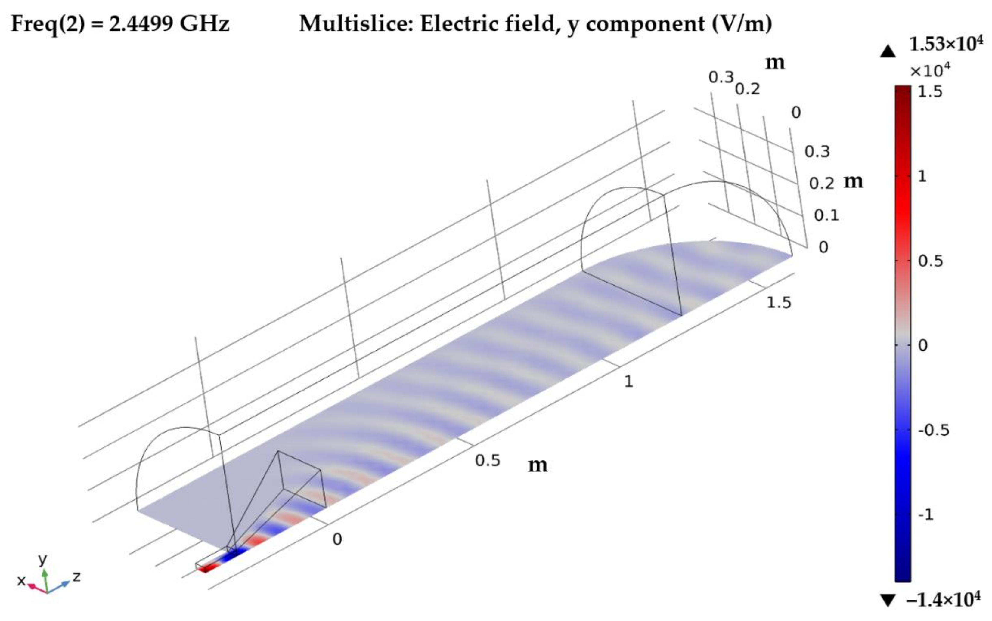
4. Verification of the Measured E-field Levels Using COMSOL Multiphysics Software
The measured E-field levels were verified using simulation in COMSOL Multiphysics. The parameters of the generator pyramidal horn antenna and the generator power parameters were used for the simulation. The simulation was performed with a modified model from [
30]. The simulation was performed using A radiofrequency module. The following parameters were set for the calculation:
Waveguide R32
Waveguide H width = 0.072136 m;
Waveguide E height = 0.034036 m;
Length of feeding waveguide = 0.1082 m.
Pyramidal Horn Antenna
Length of flared horn (along z) = 0.3048 m;
H plane, aperture width = 0.32512 m;
E-plane, aperture height = 0.24003 m.
Cutoff Frequency = 2.078E9 Hz
Fstart = 1.155. fcutoff = 2.4001E9 Hz;
Fstop = 1.203. fcutoff = 2.4998E9 Hz;
Fstep = 0.024. fcutoff = 4.9871E7 Hz;
Pgen = from 200 to 1000 W.
The simulation was performed for generator powers in the range of 200 to 1000 W. For these powers, the dependences of the E-field on the distance from the antenna aperture were obtained. With regard to the dimensions of the measuring chamber and the expected level of electromagnetic immunity,
Pgen = 200 W was selected. This power was used to measure the electromagnetic immunity of the test circuits. The simulation results are displayed in
Figure 14.
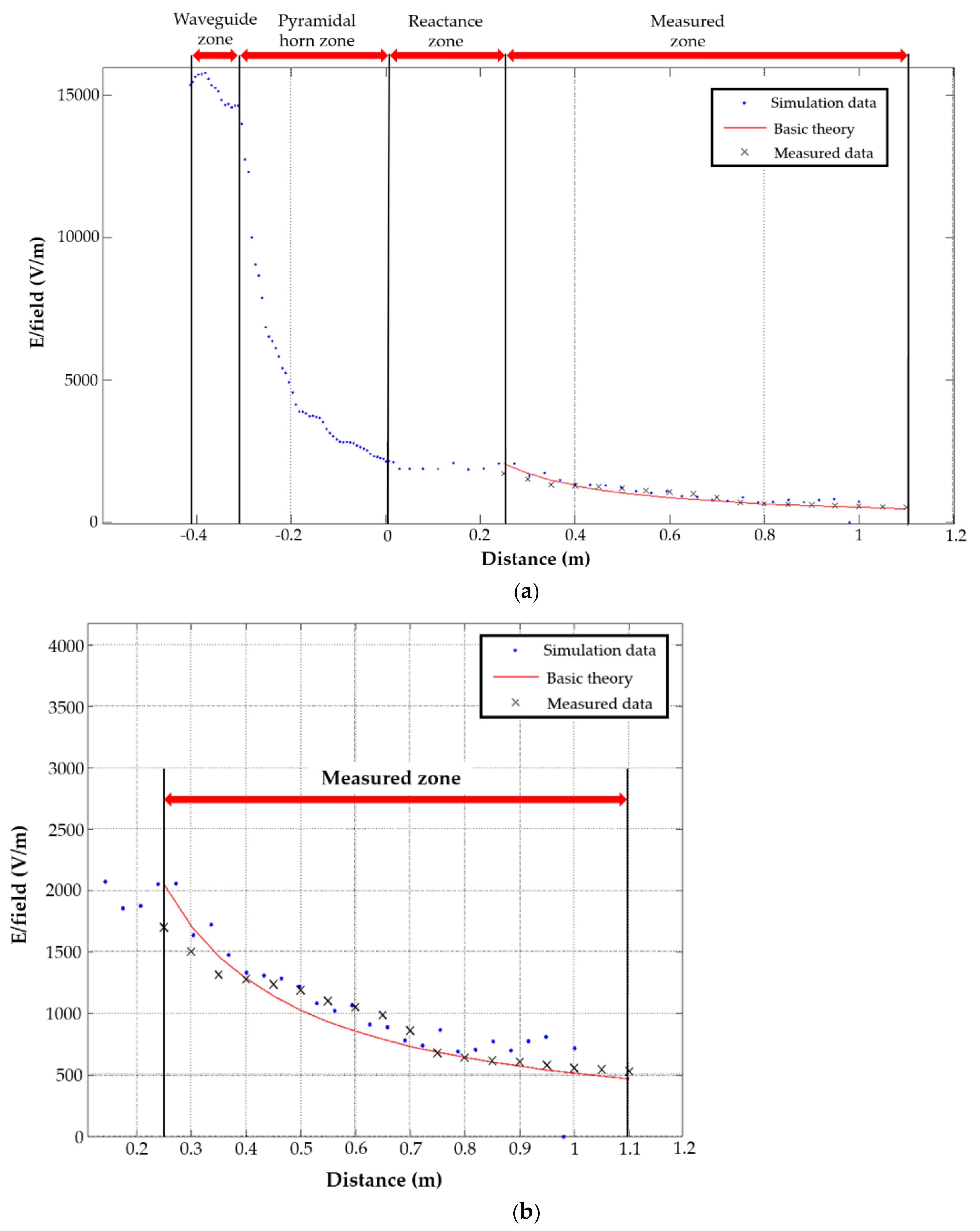
Figure 15 shows
Ey components of the E-field dependence on the distance obtained by calculation (Equations (1) and (2)) and simulations.
Figure 15a shows a full view of the
Ey component, including the E-field in the waveguide zone, in the pyramidal horn antenna zone and in the reactance zone.
Figure 15b shows a detailed view of the
Ey component in the measured zone.
5. Discussion
The NE555P test circuit was battery powered and exposed to EMP at various distances.
Table 3 shows the results of EMP immunity of the IC NE555P circuit.
The tested IC operated without faults in microwave radiation with an E-field ≤ 220 V/m. It showed faults for larger E-field levels. When the microwave power was turned off, the tested IC operated again without failure. When microwave irradiation was E-field ≥ 1700 V/m, the tested IC was destroyed.
Figure 16a shows a signal generated by the NE555P IC that was not exposed to EMP.
Figure 16b shows a signal using the IC NE555P which was exposed to EMP at a distance <2.5 m from the antenna.
Figure 16 shows that an electronic device exposed to a high EMP stopped working properly.
Figure 16b proves that an electronic device using IC NE555P was completely unusable at a certain distance from the microwave power generator antenna.
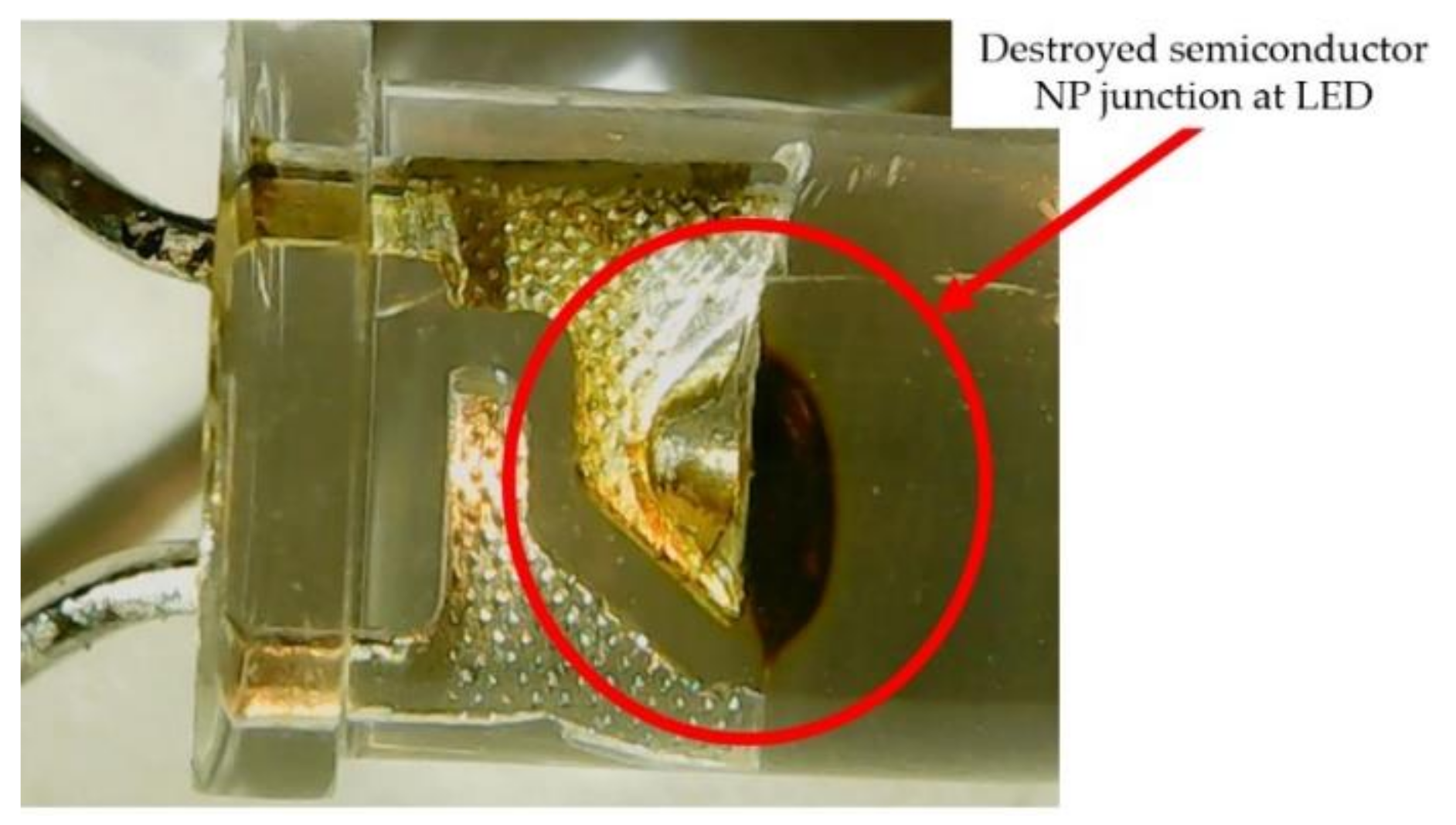
At a distance of 0.25 m from the microwave power generator antenna, the entire electronic device, including the LED, was irreversibly damaged. This destruction occurred within 2 s of the electronic device being exposed to the EMP at a distance of 0.25 m.
Figure 17 shows a detailed view of the destroyed LED NP semiconductor junction.
In addition, the electronic circuit heated up excessively during the EMP.
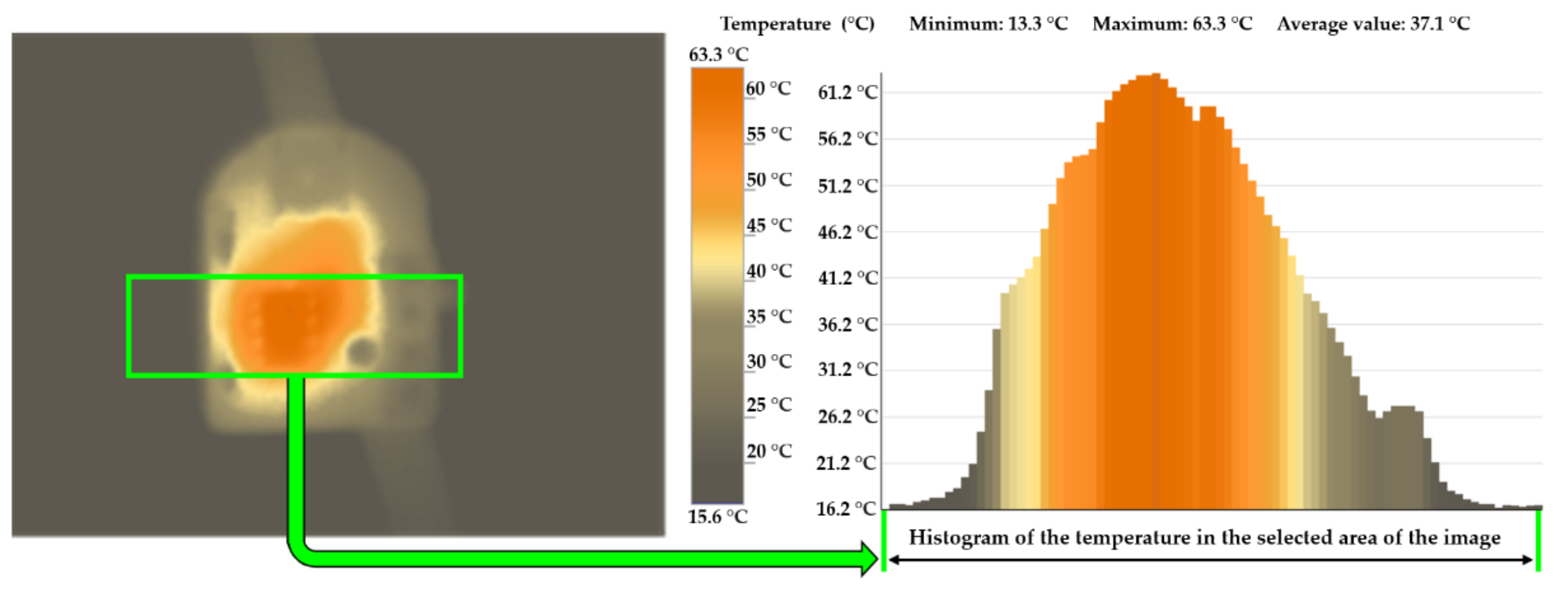
Figure 18 shows the temperature profile of a heated electronic circuit that was exposed to the EMP at a distance from the source (magnetron) of 1.1 m for 2 s. The IC NE555P is marked by the green frame.
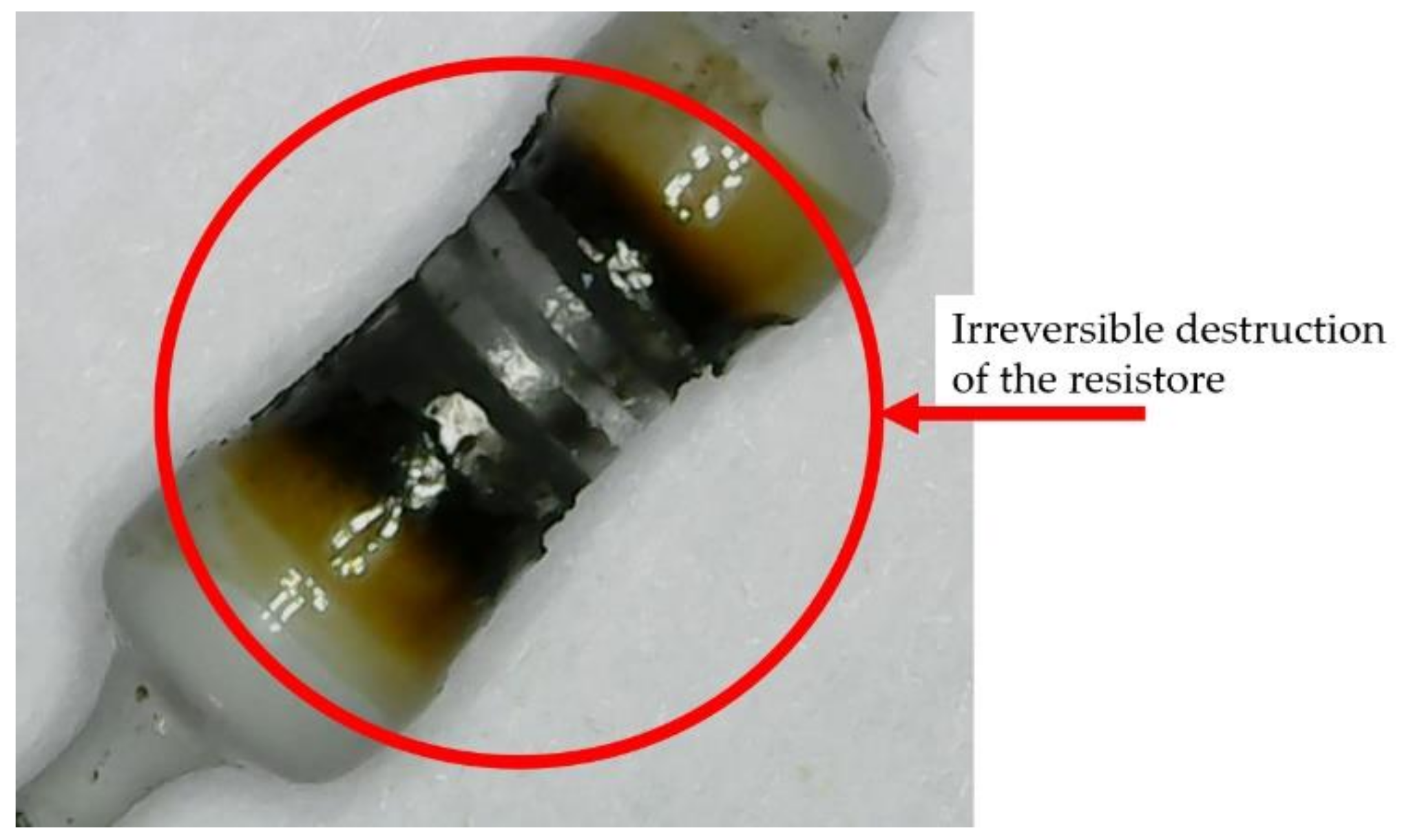
When the electronic circuit was exposed to EMP at a short distance (25 cm) from the microwave power generator antenna, all the passive components (resistor, capacitor, coil, etc.), from which the entire electronic circuit was assembled, were also destroyed.
Figure 19 shows a detailed view of the resistor after the irreversible destruction. This resistor was part of the electronic device with IC NE555P, which was exposed to EMP for 2 s at a distance of 0.25 m from the microwave power generator antenna.
The results of IC testing using (low-tech DEW generator) with generated microwave power
Pgen = 200 W are summarized in
Table 4.
The tested IC did not have additional protection against the effects of the electromagnetic field. If a higher level of electromagnetic immunity is required, various types of shielded enclosures or shielded boxes can be used, which are supplemented by other features such as various types of shielded doors, EMI/RFI (EMI - Electromagnetic interference/ RFI - Radiofrequency interference) shielded waveguide air vents, waveguide feed-through and similar. The power supply lines must be connected via special high-frequency filters (RF filters). Fiber-optic applications are very often used together with waveguide filters for data transmission from shielded cabinets and boxes. Specific examples of elements for the protection of electronic circuits against the effects of an electromagnetic field can be found, for example, in [
31].
6. Conclusions
In this paper, we introduced severe HPEM threats, in particular DEWs and IEMIs, and discussed their likely impacts on the current and future electrical power networks. The article described the basic classification of DEW and IEMI generators in terms of E-field levels and distance of the target from the DEW or IEMI generator antenna apertures. An electromagnetic immunity measurement was performed for a simple electronic circuit IC NE555P, which did not have additional protection against the effects of E-field. It was used for testing the low-tech generator described in
Section 2. The tested IC showed a malfunction when microwave irradiation reached an E-field > 220 V/m. When microwave irradiation reached an E-field ≥ 1700 V/m, the tested IC was destroyed. The measured E-field levels were compared to the E-field distribution created on the basis of a simplified theory of electromagnetic wave radiation and were verified using simulation in COMSOL Multiphysics. The tested IC was basically a resistant circuit with middle-scale integration. modern ICS such as very large-scale integration and ultra-large-scale integration are less resistant to unintentional electromagnetic interference and to intentional electromagnetic interference. Thus, it is needed, currently and also in the future, to pay more attention to increasing the electromagnetic immunity of electronic circuits used in electrical power networks. The solution is consistent electromagnetic shielding of ICs, data lines and power lines.
Author Contributions
Conceptualization, L.D., R.K. and M.P.; methodology, L.D., R.K., M.P.; validation, M.P., R.K.; formal analysis, L.D., M.P. and R.K.; investigation, L.D., R.K. and M.P.; writing—original draft preparation, L.D., R.K. and M.P.; writing—review and editing, L.D., R.K. and M.P.; visualization, L.D., M.P.; supervision, L.D.; project administration, L.D., R.K. All authors have read and agreed to the published version of the manuscript.
Funding
The research received no external funding.
Institutional Review Board Statement
Not applicable.
Informed Consent Statement
Not applicable.
Data Availability Statement
Not applicable.
Acknowledgments
The work presented in this paper has been supported by the Czech Republic Ministry of Defence—University of Defence development program “AIROPS”.
Conflicts of Interest
The authors declare no conflict of interest.
References
- Castillo-Cagigal, M.; Matallanas, E.; Caamaño-Martín, E.; Martín, Á.G. SwarmGrid: Demand-Side Management with Distributed Energy Resources Based on Multifrequency Agent Coordination. Energies 2018, 11, 2476. [Google Scholar] [CrossRef]
- Liu, W.; Guo, D.; Xu, Y.; Cheng, R.; Wang, Z.; Li, Y. Reliability Assessment of Power Systems with Photovoltaic Power Stations Based on Intelligent State Space Reduction and Pseudo-Sequential Monte Carlo Simulation. Energies 2018, 11, 1431. [Google Scholar] [CrossRef]
- Ochoa, D.; Martinez, S. Proposals for Enhancing Frequency Control in Weak and Isolated Power Systems: Application to the Wind-Diesel Power System of San Cristobal Island-Ecuador. Energies 2018, 11, 910. [Google Scholar] [CrossRef]
- Hu, H.; Wang, X.; Peng, Y.; Xia, Y.; Yu, M.; Wei, W. Stability Analysis and Stability Enhancement Based on Virtual Harmonic Resistance for Meshed DC Distributed Power Systems with Constant Power Loads. Energies 2017, 10, 69. [Google Scholar] [CrossRef]
- Faria, P.; Spínola, J.; Vale, Z. Distributed Energy Resources Scheduling and Aggregation in the Context of Demand Response Programs. Energies 2018, 11, 1987. [Google Scholar] [CrossRef]
- Casado-Vara, R.; Vale, Z.; Prieto, J.; Corchado, J.M. Fault-Tolerant Temperature Control Algorithm for IoT Networks in Smart Buildings. Energies 2018, 11, 3430. [Google Scholar] [CrossRef]
- Hu, D.; Peng, Y.; Wei, W.; Hu, Y. Distributed Secondary Control for State of Charge Balancing with Virtual Impedance Adjustment in a DC Microgrid. Energies 2020, 13, 408. [Google Scholar] [CrossRef]
- Singh, M.; Jha, R.C. Object-Oriented Usability Indices for Multi-Objective Demand Side Management Using Teaching-Learning Based Optimization. Energies 2019, 12, 370. [Google Scholar] [CrossRef]
- Galván, L.; Navarro, J.M.; Galván, E.; Carrasco, J.M.; Alcántara, A. Optimal Scheduling of Energy Storage Using A New Priority-Based Smart Grid Control Method. Energies 2019, 12, 579. [Google Scholar] [CrossRef]
- Kotsalos, K.; Miranda, I.; Silva, N.; Leite, H. A Horizon Optimization Control Framework for the Coordinated Operation of Multiple Distributed Energy Resources in Low Voltage Distribution Networks. Energies 2019, 12, 1182. [Google Scholar] [CrossRef]
- Shokri Gazafroudi, A.; Prieto, J.; Corchado, J.M. Virtual Organization Structure for Agent-Based Local Electricity Trading. Energies 2019, 12, 1521. [Google Scholar] [CrossRef]
- Šujanová, P.; Rychtáriková, M.; Sotto Mayor, T.; Hyder, A. A Healthy, Energy-Efficient and Comfortable Indoor Environment, a Review. Energies 2019, 12, 1414. [Google Scholar] [CrossRef]
- Faia, R.; Faria, P.; Vale, Z.; Spinola, J. Demand Response Optimization Using Particle Swarm Algorithm Considering Optimum Battery Energy Storage Schedule in a Residential House. Energies 2019, 12, 1645. [Google Scholar] [CrossRef]
- Radasky, W.A.; Hoad, R. An Overview of the Impacts of Three High Power Electromagnetic (HPEM) Threats on Smart Grids. In Proceedings of the International Symposium on Electromagnetic Compatibility-EMC EUROPE, Rome, Italy, 17–21 September 2012. [Google Scholar]
- Kappenman, J.G.; Radasky, W.A.; Gilbert, J.L.; Erinmez, L.A. Advanced Geomagnetic Storm Forecasting: A Risk Management Tool for Electric Power System Operations. IEEE Trans. Plasma Sci. 2000, 28, 2114–2121. [Google Scholar] [CrossRef]
- Giri, D.V. High-Power Electromagnetic Radiators: Nonlethal Weapons and Other Applications; Harvard University Press: Cambridge, MA, USA, 2004; ISBN 978-0-674-01569-2. [Google Scholar]
- Giri, D.V.; Hoad, R.; Sabath, F. Implications of High-Power Electromagnetic (HPEM) Environments on Electronics. IEEE Electromagn. Compat. Mag. 2020, 9, 37–44. [Google Scholar] [CrossRef]
- International Electrotechnical Commission. 61000-2-13:2005|IEC Webstore|Electromagnetic Compatibility, EMC, Smart City. Available online: https://webstore.iec.ch/publication/4131 (accessed on 16 April 2021).
- Giri, D.V.; Tesche, F.M.; Baum, C.E. An Overview of High-Power Electromagnetic (HPEM) Radiating and Conducting Systems. URSI Radio Sci. Bull. 2006, 2006, 6–12. [Google Scholar]
- Morton, D.; Banister, J.; Levine, J.; Naff, T.; Smith, I.; Sze, H.; Warren, T.; Giri, D.V.; Mora, C.; Pavlinko, J.; et al. A 2MV, <300ps Risetime, 100Hz Pulser for Generation of Microwaves. In Proceedings of the 2010 IEEE International Power Modulator and High Voltage Conference, Atlanta, Georgia, 23–27 May 2010. [Google Scholar]
- Morton, D.; Banister, J.; DaSilva, T.; Levine, J.; Naff, T.; Smith, I.; Sze, H.; Warren, T.; Giri, D.V.; Mora, C.; et al. HPM WBTS, a Transportable High-Power Wide-Band Microwave Source. In Proceedings of the 2010 IEEE International Power Modulator and High Voltage Conference, Atlanta, Georgia, 23–27 May 2010. [Google Scholar]
- Baum, C.E.; Baker, W.L.; Prather, W.D.; Lehr, J.M.; O’Loughlin, J.P.; Giri, D.V.; Smith, I.D.; Altes, R.; Fockler, J.; McLemore, D.M.; et al. JOLT: A Highly Directive, Very Intensive, Impulse-like Radiator. Proc. IEEE 2004, 92, 1096–1109. [Google Scholar] [CrossRef]
- Boeing: CHAMP-Lights Out. Available online: https://www.boeing.com/features/2012/10/bds-champ-10-22-12.page (accessed on 16 April 2021).
- Media, O. Raytheon EMP Weapon Tested by Boeing, USAF Research Lab-Military Embedded Systems. Available online: http://militaryembedded.com/radar-ew/sensors/raytheon-emp-missile-tested-by-boeing-usaf-research-lab (accessed on 16 April 2021).
- Testo 865 Thermal Imager|Thermal Imager|Temperature|Parameters|Testo International. Available online: https://www.testo.com/en/testo-865/p/0560-8650 (accessed on 16 April 2021).
- Misra, D. Radio-Frequency and Microwave Communication Circuits: Analysis and Design; Wiley: New York, NY, USA, 2001; ISBN 978-0-471-41253-3. [Google Scholar]
- Dunsmore, J.P. Handbook of Microwave Component Measurements: With Advanced VNA Techniques, 2nd ed.; John Wiley & Sons: Hoboken, NJ, USA, 2020; ISBN 978-1-119-47713-6. [Google Scholar]
- Kuester, E.F. Theory of Waveguides and Transmission Lines; CRC Press: Boca Raton, FL, USA, 2020; ISBN 978-1-315-37004-0. [Google Scholar]
- Smolskiy, S.M.; Kochemasov, V.N.; Belov, L.A. Handbook of RF, Microwave, and Millimeter-Wave Components, 1st ed.; Artech House: Boston, MA, USA; London, UK, 2012; ISBN 978-1-60807-209-5. [Google Scholar]
- Application Exchange: Pyramidal Horn Antenna. Available online: https://www.comsol.com/community/exchange/192/ (accessed on 16 April 2021).
- ETS-Lindgren Public Website Shielding. Available online: http://www.ets-lindgren.com/products/shielding (accessed on 19 May 2021).
Figure 1.
Illustration of the HPEM environment [
14].
Figure 1.
Illustration of the HPEM environment [
14].
Figure 2.
Magnetron used in a microwave power generator (Type 2M119J).
Figure 2.
Magnetron used in a microwave power generator (Type 2M119J).
Figure 3.
Basic block diagram of a microwave power generator.
Figure 3.
Basic block diagram of a microwave power generator.
Figure 4.
Display of a heated magnetron without optimized cooling after 90 s of full power.
Figure 4.
Display of a heated magnetron without optimized cooling after 90 s of full power.
Figure 5.
Block diagram of an optimized microwave power generator.
Figure 5.
Block diagram of an optimized microwave power generator.
Figure 6.
Internal arrangement of a microwave power generator.
Figure 6.
Internal arrangement of a microwave power generator.
Figure 7.
Thermal diagram of heated components of the microwave power generator after 10 min of full power.
Figure 7.
Thermal diagram of heated components of the microwave power generator after 10 min of full power.
Figure 8.
Thermal diagram of a heated magnetron with optimized cooling after 10 min of full power.
Figure 8.
Thermal diagram of a heated magnetron with optimized cooling after 10 min of full power.
Figure 9.
Display of a typed R32 waveguide: (a) mounting the magnetron antenna in the R32 waveguide; (b) display of waveguide temperature after 10 min of full power.
Figure 9.
Display of a typed R32 waveguide: (a) mounting the magnetron antenna in the R32 waveguide; (b) display of waveguide temperature after 10 min of full power.
Figure 10.
Assembly of a microwave power generator.
Figure 10.
Assembly of a microwave power generator.
Figure 11.
Test site for testing electronic devices in an electromagnetic field.
Figure 11.
Test site for testing electronic devices in an electromagnetic field.
Figure 12.
Special area for testing electronic devices in an electromagnetic field.
Figure 12.
Special area for testing electronic devices in an electromagnetic field.
Figure 13.
E-field sensor: (a) sleeve dipole antenna; (b) R&S RTO 1044-4GHz-20 GSa/s oscilloscope.
Figure 13.
E-field sensor: (a) sleeve dipole antenna; (b) R&S RTO 1044-4GHz-20 GSa/s oscilloscope.
Figure 14.
Simulation results - E-field dependence on the distance in COMSOL Multiphysics.
Figure 14.
Simulation results - E-field dependence on the distance in COMSOL Multiphysics.
Figure 15.
The results of the measurement, calculation and simulation of the E-field dependence on distance: (a) a full view of the Ey component dependence on the distance; (b) detailed view of the Ey component dependence on the distance.
Figure 15.
The results of the measurement, calculation and simulation of the E-field dependence on distance: (a) a full view of the Ey component dependence on the distance; (b) detailed view of the Ey component dependence on the distance.
Figure 16.
Samples from the generator with IC NE555P: (a) not exposed to EMP; (b) exposed to EMP.
Figure 16.
Samples from the generator with IC NE555P: (a) not exposed to EMP; (b) exposed to EMP.
Figure 17.
Detailed view of the damaged NP semiconductor structure with LED.
Figure 17.
Detailed view of the damaged NP semiconductor structure with LED.
Figure 18.
Heat diagram of IO NE555P exposed to EMP for 2 s at a distance of 1.1 m.
Figure 18.
Heat diagram of IO NE555P exposed to EMP for 2 s at a distance of 1.1 m.
Figure 19.
Irreversible destruction of the resistor.
Figure 19.
Irreversible destruction of the resistor.
Table 1.
Basic parameters of the magnetron 2M119J.
Table 1.
Basic parameters of the magnetron 2M119J.
| Type | Antenna | Peak Anode Voltage | Filament
(Cathode Voltage) | Current | Frequency | Transmitted Power | Weight |
|---|
| Standard | 30 mm | 4.2 kVDC | 3.3 VDC | 300 mADC | 2458 MHz | 700-900 W | 810 g |
Table 2.
Basic parameters of an optimized microwave power generator.
Table 2.
Basic parameters of an optimized microwave power generator.
| Channel | Antenna | Peak Impulse Power | Duty Factor | Pulse Width | Frequency | Transmitted Power | Waveguide |
|---|
| S | 30 mm | 1 kW | 0.01–1 | 100 μs to CW | 2450 MHz | 200–1000 W | R32 |
Table 3.
Results for EMP immunity of a circuit with IC NE555P.
Table 3.
Results for EMP immunity of a circuit with IC NE555P.
| Distance (m) | 2.5 | 2.4 | 2.0 | 1.5 | 1.1 | 1.0 | 0.9 |
| E-field (V/m) | 220 | 235 | 269 | 360 | 530 | 558 | 605 |
| Status of Circuit | Normal function | Error | Error | Error | Error | Error | Error |
| Distance (m) | 0.8 | 0.7 | 0.6 | 0.5 | 0.4 | 0.3 | 0.25 |
| E-field (V/m) | 641 | 860 | 1053 | 1190 | 1277 | 1505 | 1700 |
| Status of Circuit | Error | Error | Error | Error | Error | Error | Damage |
Table 4.
Summarized results of IC testing using a low-tech DEW generator.
Table 4.
Summarized results of IC testing using a low-tech DEW generator.
| Status of Circuit | Distance (m) | E-Field (V/m) |
|---|
| Normal function | >2.5 | ≤220 |
| Malfunction | <2.5–0.3 | >220–1500 |
| Damage | <0.25 | >1700 |
| Publisher’s Note: MDPI stays neutral with regard to jurisdictional claims in published maps and institutional affiliations. |
© 2021 by the authors. Licensee MDPI, Basel, Switzerland. This article is an open access article distributed under the terms and conditions of the Creative Commons Attribution (CC BY) license (https://creativecommons.org/licenses/by/4.0/).


