
Rotational Piezoelectric Energy Harvesting: A Comprehensive Review on Excitation Elements, Designs, and Performances

 , ,
, ,  ,
,
Abstract
1. Introduction
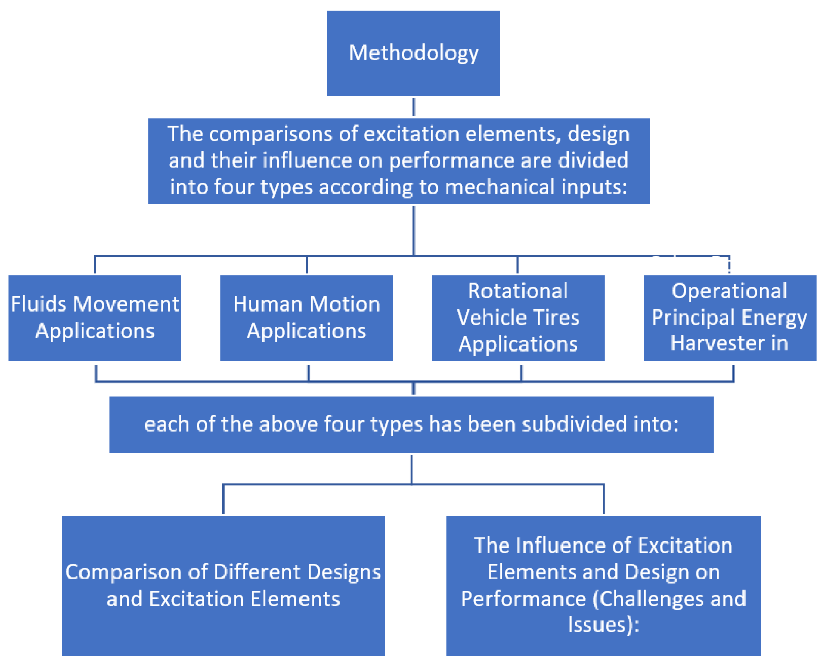
2. Methodology
3. Fluids Movement Applications
3.1. Comparison of Different Designs and Excitation Elements
3.2. The Influence of Excitation Elements and Design on Performance (Challenges and Issues)

| Number | Ref. | Input | Output | Comments | ||||||||||
|---|---|---|---|---|---|---|---|---|---|---|---|---|---|---|
| Excitation Elements | Volume (mm3) | Piezo Dimension (mm) | Polarisation Mode | Material Type Use | rpm | Frequency (Hz) | Optimal Resistance (Ω) | Power (µW) | Power Density (µW/mm3) | Mechanical Power Source | PZT Rotate or Not | Wiring | ||
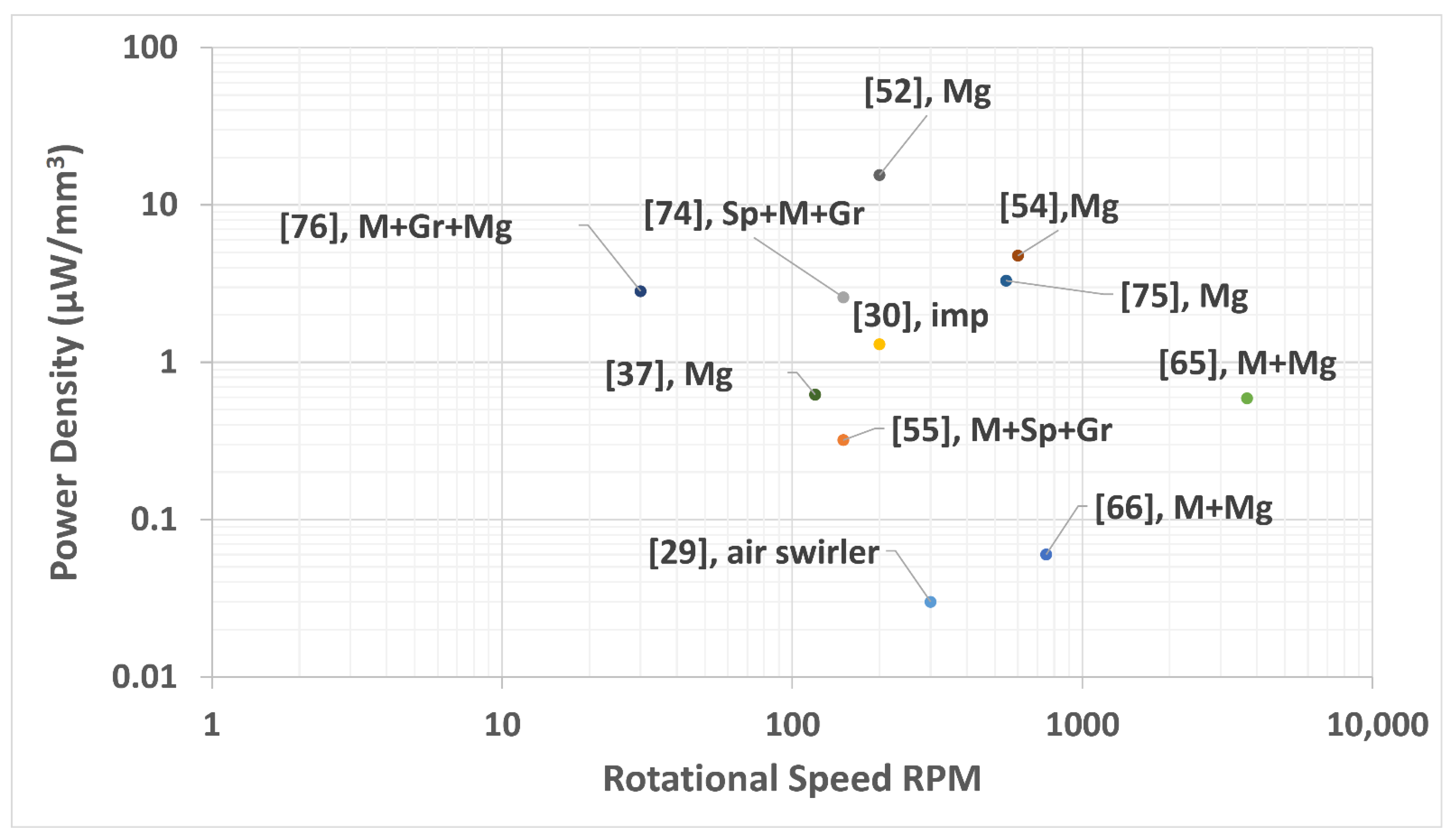
| 1 | [29] | air swirler | 96.2 | 37 × 13 × 0.2 | / | PVDF | 300 | 6 | 47 | 3 | 0.03 | Air | Not | Normal wiring |
| 2 | [55] | M + Sp + Gr | 328 | 50.8 × 25.4 × 0.254 | d31 | PZT 5A | 150 | 13.1 | 10 k | 105 | 0.32 | Air | Yes | storage rotates with the system |
| 3 | [74] | Sp + M + Gr | 326.5 | 50.8 × 25.4 × 0.254 | d31 | QP16N | 150 | 2.5 | 5 × 10⁵ | 845 | 2.588 | Air | Yes | Bluetooth |
| 4 | [30] | imp | 470 | (47 × 20 × 0.5) | / | PZT | 200 | 3.33 | 20 k | 613 | 1.3 | Air | Yes | supercapacitor |
| 5 | [66] | M + Mg | 4.26 | 16 × 3.5 × 0.076 | / | PZT-bimorph | 751 | 12.5 | 200 k | 0.25 | 0.06 | Air | Not | fixed piezo |
| 6 | [65] | M + Mg | 115 | 31.8 × 7.12 × 0.508 | d31 | Q220-A4–303YB | 3696 | 61.6 | 3300 | / | 0.59 | Air | Not | the application within the rotation area |
| 7 | [75] | Mg | 400 | 40 × 10 × 1 | / | (PZT-5H) | 546 | 9.1 | 3 × 10⁵ | 1320 | 3.3 | Air | Not | / |
| 8 | [54] | Mg | 3360 | 70 × 32 × 1.5 | / | PZT layer | 600 | 10 | 8000 k | 16000 | 4.76 | Air | Not | Normal wiring |
| 9 | [52] | Mg | 323 | (50 × 12.7 × 0.127) × 4 | d31 | PZT-5A | 200 | 16 | 247 k | 5000 | 15.5 | Air | Not | Normal wiring |
| 10 | [76] | M + Gr + Mg | 776 | 40.2 × 25.4 × 0.76 | d31 | (PPA-2011) | 30 | 34 | 25 k | 2200 | 2.835 | Air | Yes | slip ring |
| 11 | [37] | Mg | 315 | 45 × 35 × 0.2 | d31 | PZT-ceramic | 120 | / | 10 k | 196 | 0.6222 | Wat | Not | / |
| 12 | [32] | vortex-induced | / | / | d31 | PZT | / | 16.49 | 1 × 10⁵ | / | 0.035 1E + 09 | Wat | Not | / |
| 13 | [77] | Water flow + slide-crank | 166.4 | 52 × 16 × 0.2 | / | ionic polymer metal composites | 372.4 | 1 | 50 | 1 × 10⁹ | Wat | Not | / | |
| M for mass, Mg for magnetic, Gr for gravity, Sp for spring, Wat for water, air for air, imp for impact force, and /for no information from the authors. | ||||||||||||||
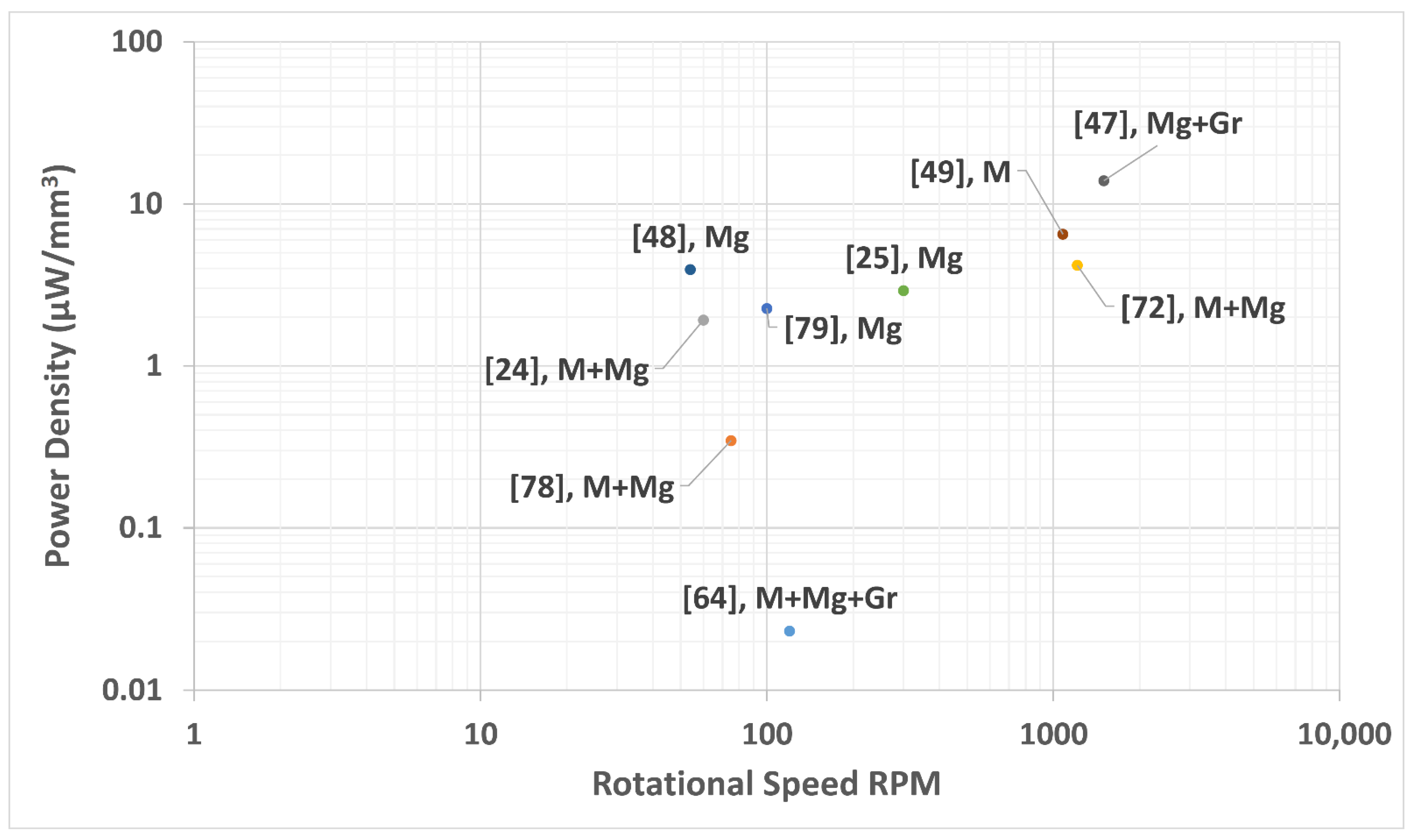
4. Human Motion Applications
4.1. Comparison of Different Designs and Excitation Elements
4.2. The Influence of Excitation Elements and Design on Performance (Challenges and Issues)
| INPUT | Output | Comments | ||||||||||||
|---|---|---|---|---|---|---|---|---|---|---|---|---|---|---|
| © | Ref. | Excitation Elements | Volume (mm3) | Piezo Dimension (mm) | Polarisation Mode | Material Type Use | rpm | Frequency (Hz) | Optimal Resistance (Ω) | Power (µW) | Power Density (µW/mm3) | Mechanical Power Source | PZT Rotate or Not | Wiring |
| 1 | [64] | M + Mg + Gr | 1850 | / | / | PZT | 120 | 4 | 150 k | 43 | 0.0232 | HM | Yes | / |
| 2 | [78] | M + Mg | 18.06 | 12 × 3.5 × 0.43 | / | piezo-electric M1100 ceramic | 75 | 1.25 | 95 k | 6.25 | 0.3461 | HM | Not | Normal wiring |
| 3 | [24] | M + Mg | 73.1 | 42 × 7.1 × 0.245 | / | PZT-5H | 60 | 1 | 80 k | 140 | 1.92 | HM | Yes | Normal wiring |
| 4 | [72] | M + Mg | 1012 | 33 × 14 × 0.73 | d31 | PZT5A | 1212 | 20.2 | 75 | 4230 | 4.18 | HM | Yes | slip ring |
| 5 | [79] | Mg | 103.8 | 6.4 × 31.8 × 0.51 | d31 | PZT-5A4E | 100 | 1.667 | / | 234.5 | 2.259 | HM | Not | Normal wiring |
| 6 | [25] | Mg | 1.2 | 5 × 4 × 0.06 | d31 | PZT | 300 | 5 | 40 k | 3.5 | 2.92 | HM | Yes | / |
| 7 | [48] | Mg | 1471 | 38.1 × 12.7 × 0.38 | / | PZT bimorph 5H | 54 | 0.9 | 15 k | 5800 | 3.94 | HM | Yes | / |
| 8 | [49] | M | 200 | 40 × 10 × 0.5 | / | PZT5H) | 1080 | 18 | 12 k | 1300 | 6.5 | HM | Yes | Normal wiring |
| 9 | [47] | Mg + Gr | 7.22 | 19.5 × 1 × 0.37 | PZT bimorph | 1500 | 25 | 151 k | 100 | 13.9 | HM | Yes | Normal wiring | |
| M for mass, Mg for magnetic, Gr for gravity, HM for human motion, and/for no information from the authors. | ||||||||||||||
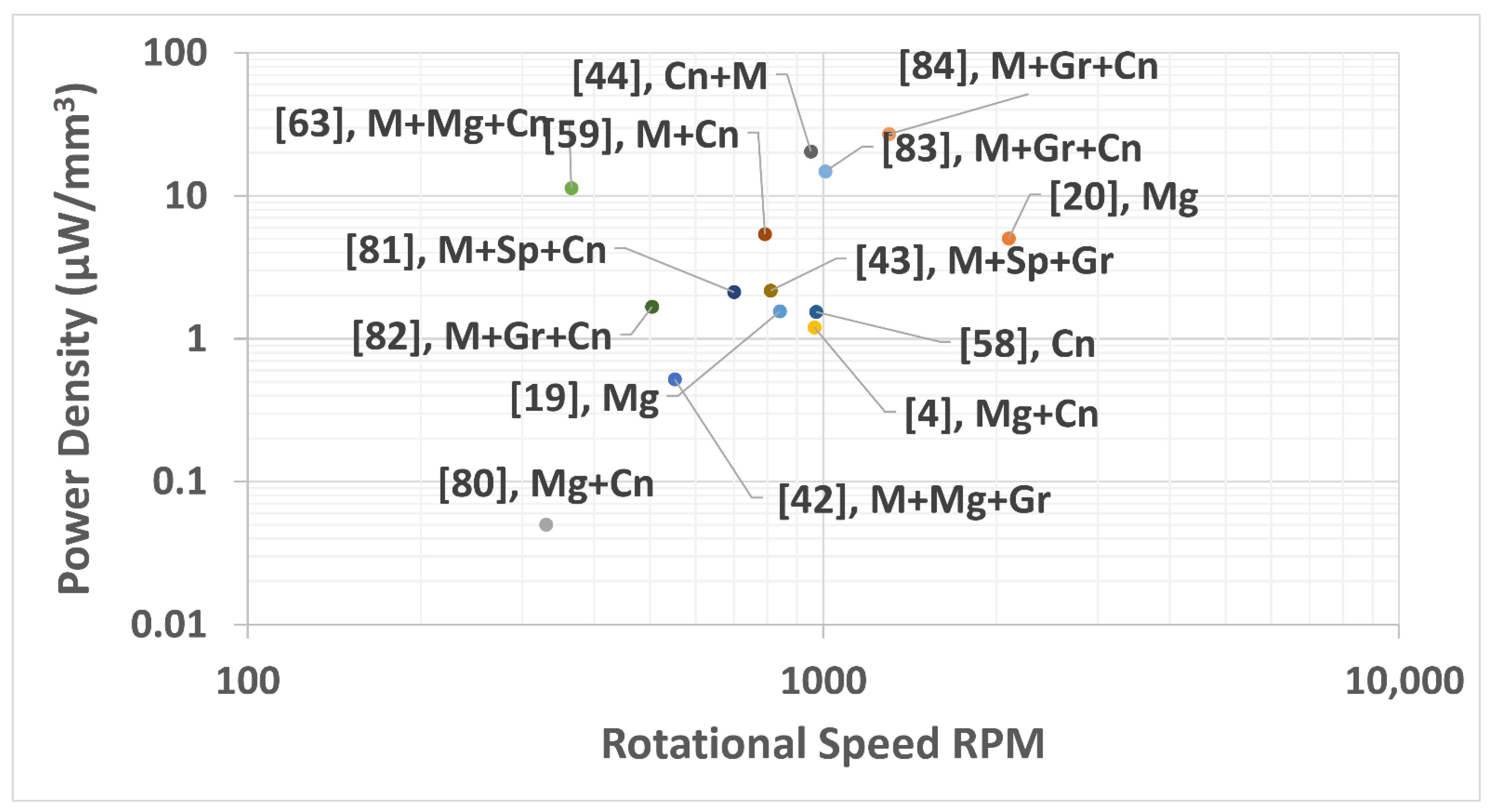
5. Rotational Vehicle Tires Applications
5.1. Comparison of Different Designs and Excitation Elements
5.2. The Influence of Excitation Elements and Design on Performance (Challenges and Issues)
| Input | Output | Comments | ||||||||||||
|---|---|---|---|---|---|---|---|---|---|---|---|---|---|---|
| Number | Ref. | Excitation Elements | Volume (mm3) | Piezo Dimension (mm) | Polarisation Mode | Material Type Use | rpm | Frequency (Hz) | Optimal Resistance (Ω) | Power (µW) | power Density (µW/mm3) | Mechanical Power Source | PZT Rotate or No | Wiring |
| 1 | [19] | Mg | 42.2 | 22 × 8 × 0.24 | / | PZT-5H | 840 | 14 | 110 k | 65.4 | 1.55 | VT | No | Direct wiring |
| 2 | [20] | Mg | 3.98 | 26.5 × 1.5 × 0.1 | / | / | 2100 | 300 | / | 20 | 5.03 | VT | No | Direct wiring |
| 3 | [80] | Mg + Cn | 64.5 | 25.4 × 12.7 × 0.2 | / | PZT 5A | 330 | 5.5 | / | 3.5 | 0.05 | VT | Yes | / |
| 4 | [4] | Mg + Cn | 30 | 25 × 12 × 0.1 | D31- | PVDF | 965 | 16 | 600 k | 36 | 1.2 | VT | Yes | Slip ring |
| 5 | [42] | M + Mg + Gr | 22.9 | 22.9 × 10 × 0.1 | / | PZT-ceramic | 552 | 9.2 | 252 k | 12 | 0.52 | VT | / | / |
| 6 | [63] | M + Mg + Cn | 21.3 | 22.9 × 9.3 × 0.1 | / | / | 365 | 6.08 | 150 k | 240 | 11.3 | VT | Yes | / |
| 7 | [58] | Cn | 80 | 25 × 6.4 × 0.5 | d31 | PZT | 972 | 16.2 | / | 123 | 1.54 | VT | Yes | slip ring |
| 8 | [59] | M + Cn | 130 | 41.3 × 6.3 × 0.5 | / | PZT | 792 | 13.2 | / | 700 | 5.38 | VT | Yes | slip ring |
| 9 | [44] | Cn + M | 24.5 | 70 × 5 × 0.07 | d33 | PZT-5H | 952 | 15.9 | 1000 k | 500 | 20.4 | VT | Yes | slip ring |
| 10 | [43] | M + Sp + Gr | 380 | 28.5 × 50 × 0.267 | / | PSI-5A4E | 810 | 13.5 | / | 825 | 2.17 | VT | Yes | slip ring |
| 11 | [81] | M + Sp + Cn | 66 | 22 × 6 × 0.5 | D31 | PVDF | 700 | 11.7 | 3300 k | 140 | 2.12 | VT | Yes | slip ring |
| 12 | [82] | M + Gr + Cn | 600 | 150 × 20 × 0.2 | / | PVDF | 504 | / | 2 × 10⁵ | 1003 | 1.6717 | VT | Yes | slip ring |
| 13 | [83] | M + Gr + Cn | 424.2 | 101 × 20 × 0.21 | / | PZT (MFC) | 1008 | 16.79 | 2 × 10⁵ | 6280 | 14.804 | VT | Yes | Sd card |
| 14 | [84] | M + Gr + Cn | 612 | 51 × 20 × 0.6 | d31 | PZT-5H | 1300 | 21.67 | 40 k | 16,520 | 26.993 | VT | Yes | slip ring |
| M for mass, Mg for magnetic, Cn for centrifugal, Gr for gravity, Sp for spring, VT for vehicle tires, and/for no information from the authors. | ||||||||||||||
6. Other Rotational Operational Principal Energy Harvester in General
6.1. Comparison of Different Designs and Excitation Elements
6.2. The Influence of Excitation Elements and Design on Performance (Challenges and Issues)
| Input | Output | Comments | ||||||||||||
|---|---|---|---|---|---|---|---|---|---|---|---|---|---|---|
| Number | Ref. | Excitation Eements | Volume (mm3) | Piezo Dimension (mm) | Polarisation Mode | Material Type Use | rpm | Frequency (Hz) | Optimal Resistance (Ω) | Power (µW) | Power Density (µW/mm3) | Mechanical Power Source | PZT Rotate or Not | Wiring |
| 1 | [85] | Shaft stress | 357 | 85 × 14 × 0.3 | d31 | PZT | 1200 | 20 | 56,170 | 744 | 2.084 | RM | Yes | slip ring |
| 2 | [73] | M + Sp + Gr | 239 | 20.57 × 0.254 × 45.8 | d31 | QP16N | 360 | 12.7 | / | 5.5 | 0.02 | RM | Yes | Arduino |
| 3 | [12] | Mg + Sp force | 53.9 | 35 × 2.2 × 0.7 | / | PZT | 546 | 34.1 | 400 k | 1230 | 22.8 | RM | Not | Normal wiring |
| 4 | [86] | Mg | 15.12 | 21.6 × 3.5 × 0.2 | / | (PZT) | 45 | 0.75 | 5 × 10⁵ | 6.37 | 0.4213 | RM | Yes | slip ring |
| 5 | [45] | M + Mg | 57.6 | 12 × 6 × 0.8 | NA | PZT | 588 | 9.8 | 3.3 M | 157 | 2.73 | RM | Yes | slip ring |
| 6 | [9] | Mg + bistable | 10.1 | 33.5 × 2 × 0.15 | d31 | PZT | 660 | 11 | 52.3 | 5.2 | RM | Not | Normal wiring | |
| 7 | [87] | M + Cn | 327.7 | 50.8 × 25.4 × 0.254 | d31 | PZT(MFC) | 180 | 0.5–3 | 1000 | 200 | 0.6102 | RM | Yes | wireless data acquisition |
| 8 | [10] | M + Mg + Gr + Cn | 40 | 20 × 10 × 0.2 | d31 | (PZT) | 550 | 9.17 | 50 k | 535 | 13.4 | RM | Yes | / |
| 9 | [11] | M + Gr | 840 | 50.8 × 31.8 × 0.26 | d31 | PZT-ceramic | 1261 | 21 | / | 7700 | 9.17 | RM | Yes | / |
| 10 | [56] | M + Gr | 86.4 | 24 × 18 × 0.2 | / | (PZT-5A) | 720 | 12 | 400 k | 1600 | 18.5 | RM | Yes | slip ring |
| 11 | [57] | M + Gr | 89 | 50.8 × 38.1 × 0.13 | d31 | PVDF& PZT | 1318 | 22 | 400 k | 6400 | 25.4 | RM | Yes | slip ring |
| 12 | [88] | G | 4.2 | / | / | / | 25 | 0.4 | 2.7 | 1.26 | 0.3 | RMG | Not | Normal wiring |
| 13 | [61] | G | 138.66 | 33 × 22 × 0.191 | / | PZT | 300 | 6 | / | 6000 | 2.55 | RMG | Not | Normal wiring |
| 14 | [60] | G + M | 4.26 | 152 × 0.028 | / | PZT-5A | 15 | 500 | 1000 | 3.72 | 0.87 | RMG | Not | Normal wiring |
| 15 | [89] | G | 3.5 | 3.5 | / | / | 1140 | 19 | 4700 | 12 | 3.43 | RMG | Not | Normal wiring |
| 16 | [90] | Gr | 61.2 | 10 × 18 × 0.17 × 2 | / | PZT-ceramics | 468 | 7.8 | 30 k | 400 | 6.54 | RMG | Not | / |
| 17 | [92] | PGr | 157.8 | 46.4 × 6.8 × 0.25 | d31 | PZT 5H | 1500 | 6.25 | 50,000 | 1566 | 9.59 | RMG | Not | Normal wiring |
| 18 | [91] | G + M + Mg | 1.2 | 5 × 3 × 0.08 | d31 | PSI5A4E, | 1140 | 19 | 180 k | 12 | 10 | RMG | No | Normal wiring |
| M for mass, Mg for magnetic, Cn for centrifugal, Gr for gravity, Sp for spring, G for gear, Pgr for planetary gear, RMfor rotationa motion, RMGfor rotational machine (gear), and/for no information from the authors. | ||||||||||||||
7. Conclusions
Author Contributions
Funding
Institutional Review Board Statement
Informed Consent Statement
Data Availability Statement
Acknowledgments
Conflicts of Interest
References
- Ando, B.; Baglio, S.; L’Episcopo, G.; Trigona, C. Investigation on Mechanically Bistable MEMS Devices for Energy Harvesting from Vibrations. J. Microelectromech. Syst. 2012, 21, 779–790. [Google Scholar] [CrossRef]
- Yang, Z.; Zhou, S.; Zu, J.; Inman, D. High-Performance Piezoelectric Energy Harvesters and Their Applications. Joule 2018, 2, 642–697. [Google Scholar] [CrossRef]
- Roundy, S.; Wright, P.K.; Rabaey, J.M. Energy scavenging for wireless sensor networks. In Norwell; Springer: Berlin/Heidelberg, Germany, 2003; pp. 45–47. [Google Scholar]
- Wu, X.; Parmar, M.; Lee, D. A Seesaw-Structured Energy Harvester with Superwide Bandwidth for TPMS Application. IEEE ASME Trans. Mechatron. 2014, 19, 1514–1522. [Google Scholar] [CrossRef]
- Kherbeet, A.S.; Salleh, H.; Salman, B.H.; Salim, M. Vibration-based piezoelectric micropower generator for power plant wireless monitoring application. Sustain. Energy Technol. Assess. 2015, 11, 42–52. [Google Scholar] [CrossRef]
- Elahi, H.; Eugeni, M.; Gaudenzi, P. A Review on Mechanisms for Piezoelectric-Based Energy Harvesters. Energies 2018, 11, 1850. [Google Scholar] [CrossRef]
- Kim, K.; Choi, H. High-efficiency high-voltage class F amplifier for high-frequency wireless ultrasound systems. PLoS ONE 2021, 16, e0249034. [Google Scholar] [CrossRef]
- Kumar, B.; Kim, S.-W. Energy harvesting based on semiconducting piezoelectric ZnO nanostructures. Nano Energy 2012, 1, 342–355. [Google Scholar] [CrossRef]
- Fu, H.; Yeatman, E.M. Rotational energy harvesting using bi-stability and frequency up-conversion for low-power sensing applications: Theoretical modelling and experimental validation. Mech. Syst. Signal Process. 2019, 125, 229–244. [Google Scholar] [CrossRef]
- Zou, H.; Zhang, W.; Li, W.; Wei, K.; Gao, Q.; Peng, Z.; Meng, G. Design and experimental investigation of a magnetically coupled vibration energy harvester using two inverted piezoelectric cantilever beams for rotational motion. Energy Convers. Manag. 2017, 148, 1391–1398. [Google Scholar] [CrossRef]
- Khameneifar, F.; Moallem, M.; Arzanpour, S. Modeling and Analysis of a Piezoelectric Energy Scavenger for Rotary Motion Applications. J. Vib. Acoust. 2011, 133, 011005. [Google Scholar] [CrossRef]
- Wu, W.; Kuo, K.; Lin, Y.; Tsai, Y. Non-contact magnetic cantilever-type piezoelectric energy harvester for rotational mechanism. Microelectron. Eng. 2018, 191, 16–19. [Google Scholar] [CrossRef]
- Dannier, A.; Brando, G.; Ruggiero, F. The Piezoelectric Phenomenon in Energy Harvesting Scenarios: A Theoretical Study of Viable Applications in Unbalanced Rotor Systems. Energies 2019, 12, 708. [Google Scholar] [CrossRef]
- Rui, X.; Zeng, Z.; Zhang, Y.; Li, Y.; Feng, H.; Yang, Z. A design method for low-frequency rotational piezoelectric energy harvesting in micro applications. Microsyst. Technol. 2020, 26, 981–991. [Google Scholar] [CrossRef]
- Su, W.J.; Lin, J.H.; Li, W.C. Analysis of a cantilevered piezoelectric energy harvester in different orientations for rotational motion. Sensors 2020, 20, 1206. [Google Scholar] [CrossRef] [PubMed]
- Rui, X.; Zeng, Z.; Li, Y.; Zhang, Y.; Yang, Z.; Huang, X.; Sha, Z. Modeling and analysis of a rotational piezoelectric energy harvester with limiters. J. Mech. Sci. Technol. 2019, 33, 5169–5176. [Google Scholar] [CrossRef]
- Mei, X.; Zhou, S.; Yang, Z.; Kaizuka, T.; Nakano, K. A quad-stable piezoelectric energy harvester for enhancing energy harvesting from rotational motion: Theoretical model and experiments. In IOP Conference Series: Materials Science and Engineering; IOP Publishing: Bristol, UK, 2019; Volume 531, p. 012010. [Google Scholar] [CrossRef]
- Fang, S.; Fu, X.; Du, X.; Liao, W.-H. A music-box-like extended rotational plucking energy harvester with multiple piezoelectric cantilevers. Appl. Phys. Lett. 2019, 114, 233902. [Google Scholar] [CrossRef]
- Xie, Z.; Kitio Kwuimy, C.A.; Wang, Z.; Huang, W. A piezoelectric energy harvester for broadband rotational excitation using buckled beam. AIP Adv. 2018, 8, 015125. [Google Scholar] [CrossRef]
- Fu, H.; Yeatman, E.M. A methodology for low-speed broadband rotational energy harvesting using piezoelectric transduction and frequency up-conversion. Energy 2017, 125, 152–161. [Google Scholar] [CrossRef]
- Zhang, Y.; Jin, Y. Stochastic dynamics of a piezoelectric energy harvester with correlated colored noises from rotational environment. Nonlinear Dyn. 2019, 98, 501–515. [Google Scholar] [CrossRef]
- Mei, X.; Zhou, S.; Yang, Z.; Kaizuka, T.; Nakano, K. A tri-stable energy harvester in rotational motion: Modeling, theoretical analyses and experiments. J. Sound Vib. 2020, 469, 115142. [Google Scholar] [CrossRef]
- Tabbai, Y.; Alaoui-Belghiti, A.; El Moznine, R.; Belhora, F.; Hajjaji, A.; El Ballouti, A. Friction and wear performance of disc brake pads and pyroelectric energy harvesting. Int. J. Precis. Eng. Manuf. Technol. 2020, 3, 111–128. [Google Scholar] [CrossRef]
- Fan, K.; Wang, L.; Zhu, Y.; Liu, Z.; Yu, B. Performance of a multipurpose piezoelectric energy harvester. Int. J. Mod. Phys. B 2017, 31, 1741007. [Google Scholar] [CrossRef]
- Li, K.; He, Q.; Wang, J.; Zhou, Z.; Li, X. Wearable energy harvesters generating electricity from low-frequency human limb movement. Microsyst. Nanoeng. 2018, 4, 24. [Google Scholar] [CrossRef]
- Ou, C.; Pinrod, V.; Davaji, B.; Lal, A. Omnidirectional low frequency energy harvester for wearable applications. J. Phys. Conf. Ser. 2019, 1407, 012122. [Google Scholar] [CrossRef]
- Han, R.; Li, K.; Wang, N.; He, Q.; Xu, D.; Li, X. Tranforming Lateral Limbs Movement to Vertical Frequency-up-Conversion (FUC) Resonance for Wearable Energy Harvesters. In Proceedings of the 2019 IEEE 32nd International Conference on Micro Electro Mechanical Systems (MEMS), Seoul, Korea, 27–31 January 2019; pp. 1029–1032. [Google Scholar] [CrossRef]
- Roundy, S.; Rantz, R.; Xue, T.; Halim, M.A. Inertial Energy Harvesting for Wearables. In 2018 IEEE SENSORS; IEEE: New York, NY, USA, 2018; pp. 1–4. [Google Scholar] [CrossRef]
- Stamatellou, A.M.; Kalfas, A.I. Experimental investigation of energy harvesting from swirling flows using a piezoelectric film transducer. Energy Convers. Manag. 2018, 171, 1405–1415. [Google Scholar] [CrossRef]
- Yang, Y.; Shen, Q.; Jin, J.; Wang, Y.; Qian, W.; Yuan, D. Rotational piezoelectric wind energy harvesting using impact-induced resonance. Appl. Phys. Lett. 2014, 105, 053901. [Google Scholar] [CrossRef]
- Gong, Y.; Yang, Z.; Shan, X.; Sun, Y.; Xie, T.; Zi, Y. Capturing Flow Energy from Ocean and Wind. Energies 2019, 12, 2184. [Google Scholar] [CrossRef]
- An, X.; Song, B.; Tian, W.; Ma, C. Design and CFD Simulations of a Vortex-Induced Piezoelectric Energy Converter (VIPEC) for Underwater Environment. Energies 2018, 11, 330. [Google Scholar] [CrossRef]
- Ramírez, J.M.; Gatti, C.D.; Machado, S.P.; Febbo, M. Energy harvesting for autonomous thermal sensing using a linked E-shape multi-beam piezoelectric device in a low frequency rotational motion. Mech. Syst. Signal Process. 2019, 133, 106267. [Google Scholar] [CrossRef]
- Bianconi, J.; Hallett, J.; Pealo, J.; Rashidi, R. A Hybrid Piezoelectric and Inductive Rotational Energy Harvester. In IOP Conference Series: Materials Science and Engineering; IOP Publishing: Bristol, UK, 2019; Volume 626. [Google Scholar] [CrossRef]
- Kyoo, N.C.; Rho, H.H. Continuous energy harvesting method using piezoelectric element. In Proceedings of the 2015 IEEE 2nd International Future Energy Electronics Conference (IFEEC), Taipei, Taiwan, 1–4 November 2015; pp. 1–4. [Google Scholar]
- Zhang, J.; Fang, Z.; Shu, C.; Zhang, J.; Zhang, Q.; Li, C. A rotational piezoelectric energy harvester for efficient wind energy harvesting. Sens. Actuators A Phys. 2017, 262, 123–129. [Google Scholar] [CrossRef]
- Cho, J.Y.; Choi, J.Y.; Jeong, S.W.; Ahn, J.H.; Hwang, W.S.; Yoo, H.H.; Sung, T.H. Design of hydro electromagnetic and piezoelectric energy harvesters for a smart water meter system. Sens. Actuators A Phys. 2017, 261, 261–267. [Google Scholar] [CrossRef]
- Fang, S.; Wang, S.; Zhou, S.; Yang, Z.; Liao, W.H. Exploiting the advantages of the centrifugal softening effect in rotational impact energy harvesting. Appl. Phys. Lett. 2020, 116, 063903. [Google Scholar] [CrossRef]
- Miao, Y.; Jia, Y. Hybrid decentralised energy for remote communities: Case studies and the analysis of the potential integration of rain energy. J. Sustain. Dev. Energy Water Environ. Syst. 2014, 2, 243–258. [Google Scholar] [CrossRef][Green Version]
- Lallart, M.; Priya, S.; Bressers, S.; Inman, D.J. Small-scale piezoelectric energy harvesting devices using low-energy-density sources. J. Korean Phys. Soc. 2010, 57, 947–951. [Google Scholar] [CrossRef]
- Gnee CHUA, K.; Fong HOR, Y.; Lim, H.C. Sensors & Transducers Raindrop Kinetic Energy Piezoelectric Harvesters and Relevant Interface Circuits: Review, Issues and Outlooks. Sens. Transducers 2016, 200, 1–15. [Google Scholar]
- Zhang, Y.; Zheng, R.; Shimono, K.; Kaizuka, T.; Nakano, K. Effectiveness Testing of a Piezoelectric Energy Harvester for an Automobile Wheel Using Stochastic Resonance. Sensors 2016, 16, 1727. [Google Scholar] [CrossRef]
- Guan, M.; Liao, W. Design and analysis of a piezoelectric energy harvester for rotational motion system. Energy Convers. Manag. 2016, 111, 239–244. [Google Scholar] [CrossRef]
- Zhu, B.; Han, J.; Zhao, J.; Deng, W. Practical Design of an Energy Harvester Considering Wheel Rotation for Powering Intelligent Tire Systems. J. Electron. Mater. 2017, 46, 2483–2493. [Google Scholar] [CrossRef]
- Li, M.; Wen, Y.; Li, P.; Yang, J.; Dai, X. A rotation energy harvester employing cantilever beam and magnetostrictive/piezoelectric laminate transducer. Sens. A Phys. 2011, 166, 102–110. [Google Scholar] [CrossRef]
- Lori, E.S.; Ebrahimi, F.; Bin Supeni, E.E.; Habibi, M.; Safarpour, H. Frequency Characteristics of a GPL-Reinforced Composite Microdisk Coupled with a Piezoelectric Layer; Springer: Berlin/Heidelberg, Germany, 2020; Volume 135, ISBN 0123456789. [Google Scholar]
- Pillatsch, P.; Yeatman, E.M.; Holmes, A.S.; Wright, P.K. Wireless power transfer system for a human motion energy harvester. Sens. Actuators A Phys. 2016, 244, 77–85. [Google Scholar] [CrossRef]
- Kuang, Y.; Yang, Z.; Zhu, M. Design and characterisation of a piezoelectric knee-joint energy harvester with frequency up-conversion through magnetic plucking. Smart Mater. Struct. 2016, 25, 085029. [Google Scholar] [CrossRef]
- Mohamad Hanif, N.H.H.; Jazlan Mohaideen, A.; Azam, H.; Rohaimi, M.E. Rotational piezoelectric energy harvester for wearable devices. Cogent Eng. 2018, 5, 1430497. [Google Scholar] [CrossRef]
- Choi, Y.M.; Lee, M.G.; Jeon, Y. Wearable Biomechanical Energy Harvesting Technologies. Energies 2017, 10, 1483. [Google Scholar] [CrossRef]
- Chow, K.-K.; Woo, T.K.; Kok, S.L.; Lau, K.-T.; Kadhim, A.M.A. Piezoelectric P(VDF-TrFE) Thick Film Based Micro-power Generator Using Flexible Substrate for Wearable Applications. In Advancement in Emerging Technologies and Engineering Applications; Springer: Singapore, 2020; pp. 109–116. ISBN 9789811500015. [Google Scholar]
- Karami, M.A.; Farmer, J.R.; Inman, D.J. Parametrically excited nonlinear piezoelectric compact wind turbine. Renew. Energy 2013, 50, 977–987. [Google Scholar] [CrossRef]
- Pozzi, M. Synchronicity and pure bending of bimorphs: A new approach to piezoelectric energy harvesting. Smart Mater. Struct. 2018, 27, 085027. [Google Scholar] [CrossRef]
- Çelik, K.; Kurt, E.; Uzun, Y. Experimental and Theoretical Explorations on the Buckling Piezoelectric Layer under Magnetic Excitation. J. Electron. Mater. 2017, 46, 4003–4016. [Google Scholar] [CrossRef]
- Febbo, M.; Machado, S.P.; Gatti, C.D.; Ramirez, J.M. An out-of-plane rotational energy harvesting system for low frequency environments. Energy Convers. Manag. 2017, 152, 166–175. [Google Scholar] [CrossRef]
- Hsu, J.; Tseng, C.; Chen, Y. Analysis and experiment of self-frequency-tuning piezoelectric energy harvesters for rotational motion. Smart Mater. Struct. 2014, 23, 075013. [Google Scholar] [CrossRef]
- Khameneifar, F.; Arzanpour, S.; Moallem, M. A Piezoelectric Energy Harvester for Rotary Motion Applications: Design and Experiments. IEEE ASME Trans. Mechatron. 2013, 18, 1527–1534. [Google Scholar] [CrossRef]
- Gu, L.; Livermore, C. Compact passively self-tuning energy harvesting for rotating applications. Smart Mater. Struct. 2012, 21, 015002. [Google Scholar] [CrossRef]
- Gu, L.; Livermore, C. Passive self-tuning energy harvester for extracting energy from rotational motion. Appl. Phys. Lett. 2010, 97, 081904. [Google Scholar] [CrossRef]
- Park, J.; Lee, S.; Kwak, B.M. Design optimization of piezoelectric energy harvester subject to tip excitation. J. Mech. Sci. Technol. 2012, 26, 137–143. [Google Scholar] [CrossRef]
- Wei, J.; Duan, L. Piezoelectric-Based Rotary Electrical Energy Generator for Harvesting Energy from Low and Highly Variable Rotary Motion. In Volume 2: Integrated System Design and Implementation; Structural Health Monitoring; Bioinspired Smart Materials and Systems; Energy Harvesting; ASME: New York, NY, USA, 2015; p. V002T07A005. [Google Scholar]
- Xue, T.; Yeo, H.G.; Trolier-McKinstry, S.; Roundy, S. Wearable inertial energy harvester with sputtered bimorph lead zirconate titanate (PZT) thin-film beams. Smart Mater. Struct. 2018, 27, 085026. [Google Scholar] [CrossRef]
- Zhang, Y.; Zheng, R.; Nakano, K.; Cartmell, M.P. rotating-tyre-induced energy harvesting Stabilising high energy orbit oscillations by the utilisation of centrifugal effects for rotating-tyre-induced energy harvesting. Appl. Phys. Lett. 2018, 143901, 2–7. [Google Scholar] [CrossRef]
- Pillatsch, P.; Yeatman, E.M.; Holmes, A.S. A piezoelectric frequency up-converting energy harvester with rotating proof mass for human body applications. Sens. Actuators A Phys. 2014, 206, 178–185. [Google Scholar] [CrossRef]
- Rezaei-Hosseinabadi, N.; Tabesh, A.; Dehghani, R. A Topology and Design Optimization Method for Wideband Piezoelectric Wind Energy Harvesters. IEEE Trans. Ind. Electron. 2015, 63, 2165–2173. [Google Scholar] [CrossRef]
- Bai, Y.; Havránek, Z.; Tofel, P.; Meggs, C.; Hughes, H.; Button, T.W. Nonlinear piezoelectric devices for broadband air-flow energy harvesting. Eur. Phys. J. Spec. Top. 2015, 224, 2675–2685. [Google Scholar] [CrossRef]
- Nabavi, S.; Zhang, L. Portable Wind Energy Harvesters for Low-Power Applications: A Survey. Sensors 2016, 16, 1101. [Google Scholar] [CrossRef] [PubMed]
- Caliò, R.; Rongala, U.; Camboni, D.; Milazzo, M.; Stefanini, C.; de Petris, G.; Oddo, C. Piezoelectric Energy Harvesting Solutions. Sensors 2014, 14, 4755–4790. [Google Scholar] [CrossRef] [PubMed]
- Shaikh, F.K.; Zeadally, S. Energy harvesting in wireless sensor networks: A comprehensive review. Renew. Sustain. Energy Rev. 2016, 55, 1041–1054. [Google Scholar] [CrossRef]
- Spanner, K.; Koc, B. Piezoelectric Motors, an Overview. Actuators 2016, 5, 6. [Google Scholar] [CrossRef]
- Mei, X.; Zhou, S.; Yang, Z.; Kaizuka, T.; Nakano, K. A passively self-tuning nonlinear energy harvester in rotational motion: Theoretical and experimental investigation. Smart Mater. Struct. 2020, 29, 045033. [Google Scholar] [CrossRef]
- Larkin, M.; Tadesse, Y. HM-EH-RT: Hybrid multimodal energy harvesting from rotational and translational motions. Int. J. Smart Nano Mater. 2013, 4, 257–285. [Google Scholar] [CrossRef]
- Ramírez, J.M.; Gatti, C.D.; Machado, S.P.; Febbo, M. An experimentally validated finite element formulation for modeling 3D rotational energy harvesters. Eng. Struct. 2017, 153, 136–145. [Google Scholar] [CrossRef]
- Machado, S.P.; Febbo, M.; Ramírez, J.M.; Gatti, C.D. Rotational double-beam piezoelectric energy harvester impacting against a stop. J. Sound Vib. 2020, 469, 115141. [Google Scholar] [CrossRef]
- Zhao, L.C.; Zou, H.X.; Yan, G.; Liu, F.R.; Tan, T.; Wei, K.X.; Zhang, W.M. Magnetic coupling and flextensional amplification mechanisms for high-robustness ambient wind energy harvesting. Energy Convers. Manag. 2019, 201, 112166. [Google Scholar] [CrossRef]
- Nezami, S.; Jung, H.; Lee, S. Design of a disk-swing driven piezoelectric energy harvester for slow rotary system application. Smart Mater. Struct. 2019, 28, 074001. [Google Scholar] [CrossRef]
- Cellini, F.; Cha, Y.; Porfiri, M. Energy harvesting from fluid-induced buckling of ionic polymer metal composites. J. Intell. Mater. Syst. Struct. 2014, 25, 1496–1510. [Google Scholar] [CrossRef]
- Halim, M.A.; Xue, T.; Rantz, R.; Zhang, Q.; Gu, L.; Yang, K.; Roundy, S. Fabrication and characterization of a wrist-driven rotational energy harvester using multiple plucked piezoelectric unimorphs. J. Phys. Conf. Ser. 2019, 1407, 012068. [Google Scholar] [CrossRef]
- Sriyuttakrai, S.; Isarakorn, D.; Boonprasert, S.; Nundrakwang, S. Practical Test of Contactless Rotational Piezoelectric Generator for Low Speed Application. In Proceedings of the 2019 IEEE PES GTD Grand International Conference and Exposition Asia (GTD Asia), Bangkok, Thailand, 20–23 March 2019; pp. 80–85. [Google Scholar] [CrossRef]
- Manla, G.; White, N.M.; Tudor, M.J. Numerical Model of a Non-Contact Piezoelectric Energy Harvester for Rotating Objects. IEEE Sens. J. 2012, 12, 1785–1793. [Google Scholar] [CrossRef]
- Yu-Jen, W.; Tsung-Yi, C.; Jui-Hsin, Y. Design and kinetic analysis of piezoelectric energy harvesters with self-adjusting resonant frequency. Smart Mater. Struct. 2017, 26, 095037. [Google Scholar] [CrossRef]
- Rui, X.; Li, Y.; Zheng, X.; Sha, Z.; Zeng, Z. Design and experimental study of a piezoelectric energy harvester in automotive spokes. J. Phys. D. Appl. Phys. 2019, 52, 355501. [Google Scholar] [CrossRef]
- Rui, X.; Zeng, Z.; Zhang, Y.; Li, Y.; Feng, H.; Huang, X.; Sha, Z. Design and Experimental Investigation of a Self-Tuning Piezoelectric Energy Harvesting System for Intelligent Vehicle Wheels. IEEE Trans. Veh. Technol. 2020, 69, 1440–1451. [Google Scholar] [CrossRef]
- Wang, Y.; Yang, Z.; Cao, D.; Huang, W. Compressive-mode piezoelectric energy harvesting in translational and rotational systems. In Proceedings of the 2019 IEEE/ASME International Conference on Advanced Intelligent Mechatronics (AIM), Hong Kong, China, 8–12 July 2019; pp. 1598–1603. [Google Scholar] [CrossRef]
- Grzybek, D.; Micek, P. Piezoelectric energy harvesting based on macro fiber composite from a rotating shaft. Phys. Scr. 2019, 94, 095802. [Google Scholar] [CrossRef]
- Ma, T.; Gao, Q.; Li, Y.; Wang, Z.; Lu, X.; Cheng, T. An Integrated Triboelectric–Electromagnetic–Piezoelectric Hybrid Energy Harvester Induced by a Multifunction Magnet for Rotational Motion. Adv. Eng. Mater. 2020, 22, 1900872. [Google Scholar] [CrossRef]
- Ramírez, J.M.; Gatti, C.D.; Machado, S.P.; Febbo, M. A piezoelectric energy harvester for rotating environment using a linked E-shape multi-beam. Extreme Mech. Lett. 2019, 27, 8–19. [Google Scholar] [CrossRef]
- Janphuang, P.; Isarakorn, D.; Briand, D.; de Rooij, N.F. Energy harvesting from a rotating gear using an impact type piezoelectric MEMS scavenger. In Proceedings of the 2011 16th International Solid-State Sensors, Actuators and Microsystems Conference, Beijing, China, 5–9 June 2011; pp. 735–738. [Google Scholar]
- Janphuang, P.; Lockhart, R.; Briand, D.; de Rooij, N.F. On the optimization and performances of a compact piezoelectric impact MEMS energy harvester. In Proceedings of the 2014 IEEE 27th International Conference on Micro Electro Mechanical Systems (MEMS), San Francisco, CA, USA, 26–30 January 2014; pp. 429–432. [Google Scholar]
- Yang, B.; Yi, Z.; Tang, G.; Liu, J. A gullwing-structured piezoelectric rotational energy harvester for low frequency energy scavenging. Appl. Phys. Lett. 2019, 115, 063901. [Google Scholar] [CrossRef]
- Janphuang, P.; Lockhart, R.A.; Isarakorn, D.; Henein, S.; Briand, D.; de Rooij, N.F. Harvesting Energy from a Rotating Gear Using an AFM-Like MEMS Piezoelectric Frequency Up-Converting Energy Harvester. J. Microelectromech. Syst. 2015, 24, 742–754. [Google Scholar] [CrossRef]
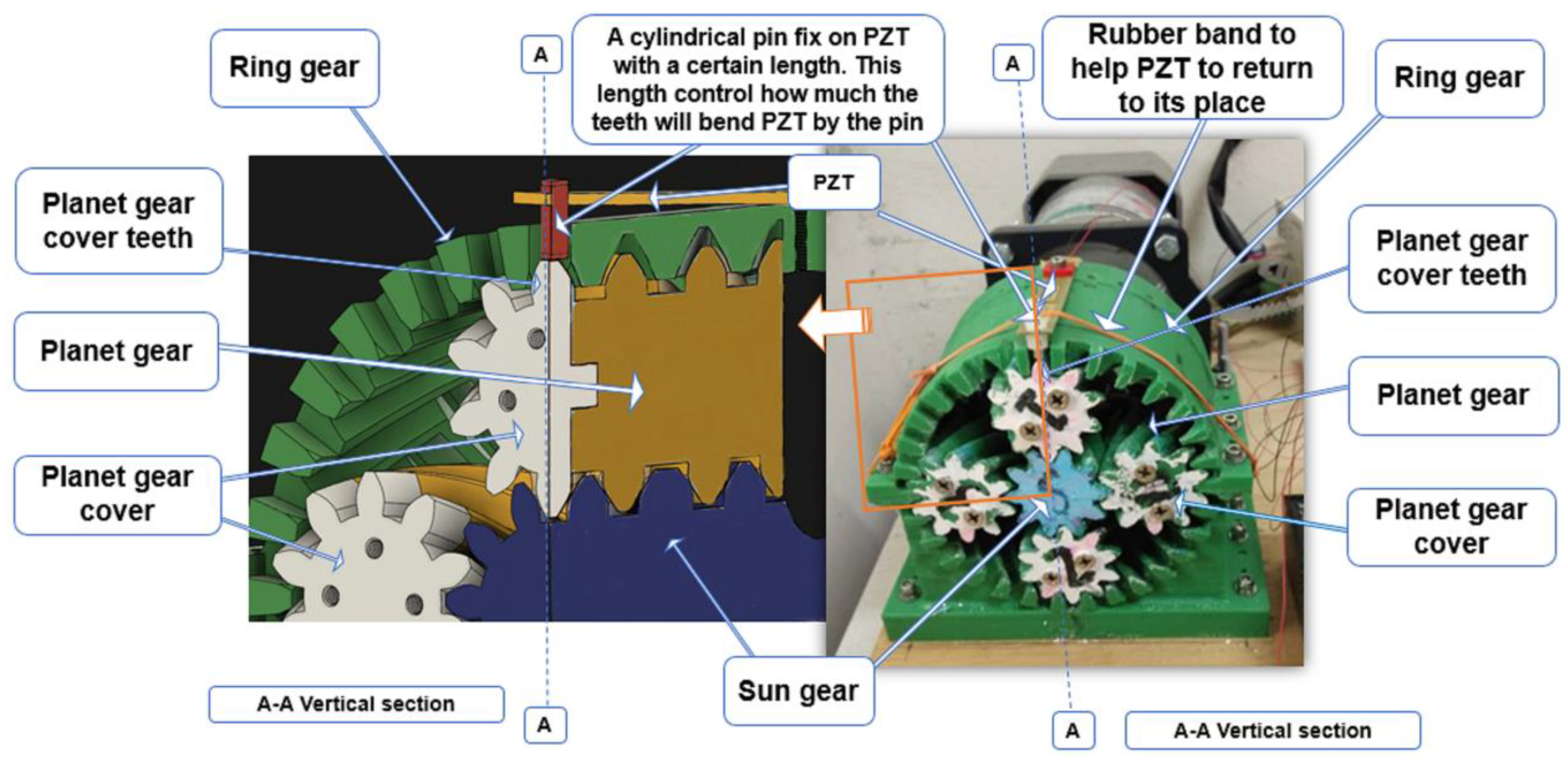
- Chilabi, H.J.; Salleh, H.; Supeni, E.E.; As’Arry, A.B.; Rezali, K.A.; Atrah, A.B. Harvesting energy from planetary gear using piezoelectric material. Energies 2020, 13, 223. [Google Scholar] [CrossRef]


Publisher’s Note: MDPI stays neutral with regard to jurisdictional claims in published maps and institutional affiliations. |
© 2021 by the authors. Licensee MDPI, Basel, Switzerland. This article is an open access article distributed under the terms and conditions of the Creative Commons Attribution (CC BY) license (https://creativecommons.org/licenses/by/4.0/).
Share and Cite
Chilabi, H.J.; Salleh, H.; Al-Ashtari, W.; Supeni, E.E.; Abdullah, L.C.; As’arry, A.B.; Rezali, K.A.M.; Azwan, M.K. Rotational Piezoelectric Energy Harvesting: A Comprehensive Review on Excitation Elements, Designs, and Performances. Energies 2021, 14, 3098. https://doi.org/10.3390/en14113098
Chilabi HJ, Salleh H, Al-Ashtari W, Supeni EE, Abdullah LC, As’arry AB, Rezali KAM, Azwan MK. Rotational Piezoelectric Energy Harvesting: A Comprehensive Review on Excitation Elements, Designs, and Performances. Energies. 2021; 14(11):3098. https://doi.org/10.3390/en14113098
Chicago/Turabian StyleChilabi, Haider Jaafar, Hanim Salleh, Waleed Al-Ashtari, E. E. Supeni, Luqman Chuah Abdullah, Azizan B. As’arry, Khairil Anas Md Rezali, and Mohammad Khairul Azwan. 2021. "Rotational Piezoelectric Energy Harvesting: A Comprehensive Review on Excitation Elements, Designs, and Performances" Energies 14, no. 11: 3098. https://doi.org/10.3390/en14113098
APA StyleChilabi, H. J., Salleh, H., Al-Ashtari, W., Supeni, E. E., Abdullah, L. C., As’arry, A. B., Rezali, K. A. M., & Azwan, M. K. (2021). Rotational Piezoelectric Energy Harvesting: A Comprehensive Review on Excitation Elements, Designs, and Performances. Energies, 14(11), 3098. https://doi.org/10.3390/en14113098