Article

Swarm Intelligence-Based Methodology for Scanning Electron Microscope Image Segmentation of Solid Oxide Fuel Cell Anode

Department of Fundamental Research in Energy Engineering, AGH University of Science and Technology, 30 Mickiewicza Ave., 30059 Cracow, Poland
*
Author to whom correspondence should be addressed.
These authors contributed equally to this work.
Energies 2021, 14(11), 3055; https://doi.org/10.3390/en14113055
Submission received: 20 April 2021 / Revised: 20 May 2021 / Accepted: 21 May 2021 / Published: 25 May 2021
(This article belongs to the Special Issue Approaches for Energy Storage, Sensing and Electrocatalysis)

Abstract

:
Segmentation of images from scanning electron microscope, especially multiphase, poses a drawback in their microstructure quantification process. The labeling process must be automatized due to the time consumption and irreproducibility of the manual labeling procedure. Here we show a swarm intelligence-driven filtration methodology performed on raw solid oxide fuel cell anode’s material images to improve the segmentation methods’ performance. The methodology focused on two significant parts of the segmentation process, which are filtering and labeling. During the first one, the images underwent filtering by applying a series of filters, whose operation parameters were determined using Particle Swarm Optimization upon a dedicated cost function. Next, Seeded Region Growing, k-Means Clustering, Multithresholding, and Simple Linear Iterative Clustering Superpixel algorithms were utilized to label the filtered images’ regions into consecutive phases in the microstructure. The improvement was presented for three different metrics: the Misclassification Ratio, Structural Similarity Index Measure, and Mean Squared Error. The obtained distribution of metrics’ performances was based on 200 images, with and without filtering. Results indicate an improvement up to 29%, depending on the metric and method used. The presented work contributes to the ongoing efforts to automatize segmentation processes fully for an increasing number of tomographic measurements, particularly in solid oxide fuel cell research.

1. Introduction

As the world seeks to achieve nearly zero carbon-dioxide emission by 2050, hydrogen plays a pivotal role in the transition, as storage for electricity produced from renewable sources and supplementary power generation. One can convert hydrogen to electricity directly using fuel cell technology. Fuel cells’ types vary depending on the operating temperature and the material used for their components. Among all fuel cells, solid oxide fuel cells (SOFC) play a particularly important role in the transition process, as they can convert hydrogen from multiple sources, such as natural gas (grey hydrogen) [1], tail gas, associated gas, and other by-products from existing plants (blue hydrogen) [2], and finally, green hydrogen from renewables [3]. A typical commercial SOFC (see Figure 1) consists of solid gas-tight electrolyte (Yttria-Stabilized Zirconia, YSZ), a multi-layer cathode (Lanthanum Strontium Cobalt Ferrite, LSCF, - Gd-doped ceria, GDC composite as a functional layer), and an anode (Ni-YSZ). The electrodes are made of ceramic–metallic composite, which exhibits a complex, multiphase microstructure. Thus, the SOFC electrode is characterized by high internal complexity. In this respect, the electrode’s ability to effectively transport the species to and from the reaction site, described by its microstructure’s morphological parameters, is of great significance for the cell’s overall performance [4,5]. Elaboration of those parameters, like porosity, connectivity, or triple-phase boundary density (reaction domain), becomes a crucial part of any SOFC analysis [6,7].
In 2006, a powerful tool for acquiring high-quality microstructural information of SOFC electrodes was introduced to the field, namely, Focused Ion Beam—Scanning Electron Microscopy (FIB-SEM), by Wilson et al. [8]. The FIB-SEM electron tomography procedure applies gallium ions to mill thin sections from the exposed electrode surface, which is simultaneously followed by imaging with Scanning Electron Microscope (SEM). Sequential milling and imaging yield a serial set of consecutive images of the electrode. Together, the obtained 2D images can be combined into a three-dimensional digital representation of the anode microstructure. The information which can be extracted from those images can be further used in modeling and improving the performance of SOFC electrodes [9,10]. The applicability of the FIB-SEM technique for the investigation of SOFC anode microstructures has been widely confirmed [9,11,12,13,14,15].
In order to perform a complete microstructure’s quantitative examination, it is necessary to reconstruct a three-dimensional structure from the binary images, in which every voxel (three-dimensional pixel) needs to be labeled into one of three phases [10,16]. It is achieved by aligning, cropping, and then segmenting the slices. During segmentation, pixels are clustered into non-overlapping, homogeneous regions based on an imposed membership criteria [16]. As a result, an image is divided into different regions, which can represent objects or parts of objects [17,18]. For the ceramic fuel cell’s anode, those regions represent the three phases, which are visible in the SEM images: nickel, YSZ, and pores. Phase segmentation of tomography micrograph data with a complex internal structure has been performed primarily by manual delineation of the phases. However, this is a highly laborious process, which is also prone to subjectivity and lack of repeatability [19]. Mozdzierz et al. [20] proposed a filtering scheme and semi-automatic procedure for image segmentation using the Fiji distribution of the open-source image analysis software, ImageJ (version 1.52i, National Institutes of Health, Bethesda, MD, USA) [21,22]. Sciazko et al. [23] introduced the Convolutional Neural Networks architecture, which served as an artificial pore-infiltration technique, to reduce the reconstruction time by an order of magnitude. In addition, some attempts on automating the Seeded Region Growing (SRG) algorithm may be found in the open literature. Law et al. [24] presented a threshold value optimization method and a Genetic Algorithm (GA)-based seed selection method, but the possibility of under-segmentation occurring is an issue and was not solved. To overcome the need for manual threshold value selection, Whitney et al. [25] proposed a method that performs histogram analysis of voxel similarity to automatically determine a stopping criterion, but it has a major drawback, which is the requirement of seed-point selection by the user. Fang et al. [26] performed automatic SRG segmentation for high-efficiency carbon-fiber-reinforced polymer (CFRP) detection and binary segmentation to minimize uneven illumination in optical pulsed thermography. It is a common practice to extend the principal segmentation algorithms in order to improve its efficiency. Solid Oxide Fuel Cells anode micrographs’ phase identification was studied by Fu et al. [27]. In their approach, the authors introduced the two-stage LPG-PCA filtering (de-noising) framework to remove artifacts and equalize the brightness of images, as well as Fuzzy Clustering for phase segmentation. Another approach was made by Yang et al. [28], who aided their Fuzzy C-means clustering algorithm with Particle Swarm Optimization in order to improve the adaptive search for initial clustering centers and help avoid local optima.
The literature review unveils the need to further develop the segmentation process, particularly for solid oxide fuel cell application. Here we show a methodology for fast image processing of the FIB-SEM triple-phase micrographs of a solid oxide fuel cell anode. In the proposed approach, the elaborated algorithm initially performs multilevel, optimized preprocessing on the raw image data utilizing morphological corrections and advanced filtering aided by Particle Swarm Optimization (PSO) [29]. PSO was selected to increase the convergence of the optimization in comparison to a genetic algorithm [30]. Next, segmentation method is harnessed to label the regions in the preprocessed images into three phases in the SOFC anode. The novelty lies in the employment of Particle Swarm Optimization for the adjustment of filtering and segmenting process parameters. This work responds to a rapid drive toward improvements in digital image processing and offers a supervised segmentation algorithm for FIB-SEM microstructural images taken from the Ni-YSZ anode of a solid oxide fuel cell.

2. Methodology

2.1. Image Acquisition

Three-dimensional reconstruction of SOFC electrodes is usually obtained with Focused Ion Beam—Scanning Electron Microscopy (FIB-SEM). This technology offers the analysis of the volume of interest at a nanometric scale and enables the evaluation of critical microstructural features, such as volume fraction, interface areas, three-phase boundary density, connectivity, and the tortuosity factor of specific phases [31,32]. The entire procedure works in the following manner: The FIB gun applies galium ions Ga+ to mill thin (ca. 50 nm) sections of the electrode so that a new observation surface is exposed. This is followed by capturing the cross-section image with a SEM detector. The sequence of milling and imaging, known as "cut-and-see", is repeated until a series of 200–300 cross-sections are acquired. The applicability of the FIB-SEM technique for the investigation of microstructure features has been widely confirmed [9,33,34].
Anode samples were obtained from experimental button cells made with a robocasting technique. A self-made anode suspension based on NiO-YSZ powder with an addition of dispersant and solvents was prepared by mixing the constituents in the relation shown in Table 1.
After deposition of the anode and cathode (LSM, fuelcellmaterials, USA) suspensions and sintering, the cell was reduced and tested electrochemically to prove its correct assembly.
After the power generation test, the sample was impregnated with Struers Epofix resin, which was heated up to 45 °C and mixed for 10 minutes. Next, the hardener was added to the resin and mixed for another 5 minutes inside the hot bath. A 5 mm × 5 mm sample was located inside a small plastic container and then in a vacuum impregnation unit. After reaching the inside pressure of 0.35 bar, the resin was injected into the container. The sample was kept under vacuum conditions for another 10 minutes. Filling the pores with epoxy resin is necessary for the recognition of the pore area during SEM observation. The impregnated sample was cut and polished using sandpaper with the sheets’ grit varying from 400 to 1800, followed by the polishing cotton sheet and diamond paste to prepare the FIB-SEM observation sample. The images used in this study were divided into two groups depending on the electron detector used. Images were obtained with Zeiss NVision 40 using an in-lens secondary electron detector (Mag 3 k, EHT = 1.5 kV, WD = 5 mm). We decided to analyze micrographs instead of SEM images to consider all experimental artifacts present during this type of measurement. The main experimental artifacts that can be found in the investigated FIB-SEM micrographs are waterfall effects, brightness differences, and unfilled pores (not penetrated by epoxy). The experimental artifacts mentioned above can impact the filtering process, as well as phase labeling.

2.2. Images Filtering

Applying a suitable image enhancement method is pivotal in image processing and enables improving image segmentation accuracy. However, it is necessary to use a combination of different filters together to achieve satisfactory results. The greatest challenge is selecting appropriate values of parameters describing the filters. The manual selection is quite complex, subject to human intuition, has poor reproducibility, and is extremely time-consuming. Here we show a supervised automatic adjustment of filtering parameters using particle swarm optimization. The procedure was performed using the MATLAB programming language (MathWorks, Inc.). Two hundred images were segmented manually using the commercial Avizo® Thermo Fisher Scientific analysis software to provide a set of training and test data for PSO. The manually segmented images are denoted as ground-truth data. During learning, 11 manually segmented images were used as a learning set to evaluate fitness function. The learning set consists of images uniformly distributed in the sample. Choosing only a few images is driven by the application of the presented methodology—only a fraction of all images has to be manually segmented in order to perform optimization and automatic filtering. Each phase was assigned to the grayscale level in the manually segmented images: pore 0, YSZ 127, Ni 255. The optimization function is an average of the sum of absolute differences (SAD), which is a measure of the similarity between image blocks and the Structural Similarity Index Measure (SSIM). SSIM is a method proposed by Wang et al. [35] for measuring the similarity between the image being compared and the ground truth. Both SAD and SSIM are image quality metrics that allow the comparison of a filtered image with the manually segmented one quantitatively. The framework for the supervised automatic filtering procedure is described in Algorithm 1. A list of the filters and optimized parameters is presented in Table 2. The filters’ application order was selected arbitrarily and by trial and error, and presented in order. The Illumination correction filter’s parameter—the correction factor—was regarded as the ratio between deviations of luminances described by Equation (5) from the Ref. [36]. Sharpening the edges and smoothening the rest of an image was conducted by the following steps:
  • Preliminary filtering:
    1.1.
    Apply 2D median filtering with 3 × 3 window
    1.2.
    Adjust image intensity by mapping into range 0 to 1
  • Sharpen preliminary image with Unsharp masking
  • Make mask by finding edges using the Canny edge detection algorithm [37]
  • Dilate the mask with a disk-shaped structuring element (the radius r = 3)
  • Apply Gaussian filter on preliminary image to smooth the image and adjust image intensity
  • Merge sharpened and smoothed images using mask in following manner:
    6.1.
    Fill masked region from sharpened image
    6.2.
    Fill rest of image with smoothed image
  • Repeat the preliminary filtering procedure.
Algorithm 1 Filter optimization algorithm.
Require: 
Given sequence of N filters and their parameters G = ( f i , p i ) | 0 i N , set of M pairs of original and manualy segmented images H = ( I i , I ref , i ) | 0 i M and PSO optimization parameters p PSO
1:
γ min =
2:
PSOoptimizer = InitializePSO p PSO  // Initialize optimizer
3:
do
4:
 NextGeneration(PSOoptimizer)
5:
P = GetPopulation PSOoptimizer // Get current population
6:
// For all sequences of proposed filters and their parameters
7:
for S i P do
8:
  for I j , I ref , j H do
9:
    J j = I j
10:
   // For all filters and their parameters in given sequence
11:
   for f k , p k S do
12:
     J j = f k p k , J j
13:
   end for
14:
    D j = 0.5 · SSIM ( J j , I ref , j ) + 0.5 · SAD ( ( J j , I ref , j )
15:
  end for
16:
   γ i = i = 1 M D j
17:
  if γ i < γ min then
18:
    γ min = γ i
19:
    S best = S i
20:
  end if
21:
end for
22:
while convergenceCriteria(PSOoptimizer)

2.3. Image Segmentation

The development of mathematical methods for image processing became a rapidly growing research field during the last few decades. One of the key processes is segmentation (or labeling), in which the task is to separate the image into homogeneous regions, usually foreground and background. It is performed according to various criteria, such that pixels in the image with the same label share certain characteristics. It is typically performed on noisy images, and, due to the flaws incorporated in every measurement, it is a great challenge to get satisfactory results [45].
For the segmentation of intensity images, four main approaches can be distinguished, namely, the threshold technique, boundary-based technique, region-based techniques, and hybrid techniques combining boundary and region criteria [46]. The Seeded Region Growing algorithm is an image segmentation method based on the homogeneity principle that refers to pixels with comparable properties, which are clustered collectively to form homogeneous regions [47]. The Seeded Region Growing approach to image segmentation is segmenting an image into regions with respect to a set of n seeds. Each region is a connected group of one or more points (pixels) and is represented by a set A i , where i=1,2,...,n. Let T be a set of all unallocated pixels that border at least one A i set element, that is:
T = { x i = 1 n A i : N ( x ) i = 1 n A i } ,
where N ( x ) represents the set of immediate neighbors, for a hexagonal grid, it is 6, and for a square grid, it is either 4 or 8 (for a so-called aggressive search). Every single step of the algorithm involves examining the neighbors of each x T . When N ( x ) intersects a region A j , then a measure of the similarity (difference) between x and the intersected region, δ ( x ) , is calculated. In the simplest form, it is defined as:
δ ( x ) = g ( x ) mean y A j g ( y ) ,
where g ( x ) is the intensity of the pixel x. If N ( x ) intersects more than one region, then A j is taken to be the region for which δ ( x ) is minimized. Next, a z T is found, so that [46,48]:
δ ( z ) = min x T { δ ( x ) } .
Finally, if δ ( z ) < τ , τ is a certain threshold, then this neighbour is appended to the region.
The vital step in the region-growing procedure is the seed point selection. It settles on various criteria (which can be initially selected manually by the user) and the overall segmentation via the region-growing technique, so it requires an appropriate human–computer interaction method [47]. A perfect candidate seed point should meet certain criteria, such as:
  • Should be inside the region and near the center of the region;
  • Assuming most of the pixels in the region of interest (ROI) belong to the region (i.e., ROI is not too big compared to the region), the feature of this seed point should be close to the region average;
  • The distances from the seed pixel to its neighbors should be small enough to allow continuous growing [47].
Seed generation was performed in the following manner:
  • Image is initially segmented with the fast automatic segmentation method (we have used Multithresholding);
  • For each phase, perform one iteration of image erosion;
  • For each phase, define seeds as centers of mass of each separated region.
When seed points are found, the growing procedure can begin. It will continue until there are no points left outside the perimeter of the region, which meet the similarity criteria (determined by the thresholds).
For the proposed algorithm, three thresholds, τ N i , τ Y S Z , and τ P o r e for each phase, moderate the segmentation process. The thresholds τ N i , τ Y S Z , and τ P o r e are found via PSO search against the Mean Square Error (MSE) optimization function. The scheme of the proposed segmentation methodology was summarized in Algorithm 2. The ranges of the optimized threshold are the same for each phase and equal to 0–0.15.
Algorithm 2 SRG optimization algorithm.
Require: 
Given set of M pairs of unsegmented and manually segmented images H = ( I i , I ref , i ) | 0 i M and PSO optimization parameters p PSO
1:
// Seed points generation
2:
for I i H do
3:
I i , T = imageThreshold ( I i )
4:
P i = extractPhases ( I i , T )
5:
// For each phase in thresholded image
6:
for P i , j P i do
7:
   P i , j = imageErosion ( P i , j )
8:
   C i = centersOfMass ( P i , j )
9:
end for
10:
end for
11:
γ min =
12:
PSOoptimizer = InitializePSO p PSO  // Initialize optimizer
13:
do
14:
 NextGeneration(PSOoptimizer)
15:
P = GetPopulation PSOoptimizer // Get current population
16:
// For all proposed thresholds for the SRG algorithm
17:
for t i P do
18:
  for I j , I ref , j H do
19:
    J i = SRG ( I j , t i , C i )
20:
    D j = MSE ( I ref , j , J i )
21:
  end for
22:
   γ i = i = 1 M D j
23:
  if γ i < γ min then
24:
    γ min = γ i
25:
    t best = t i
26:
  end if
27:
end for
28:
while convergenceCriteria(PSOoptimizer)

3. Results

Filters’ parameters obtained with the use of the PSO algorithm are presented in Table 3. Optimized threshold values for each phase for both original and filtered images are presented in Table 4.
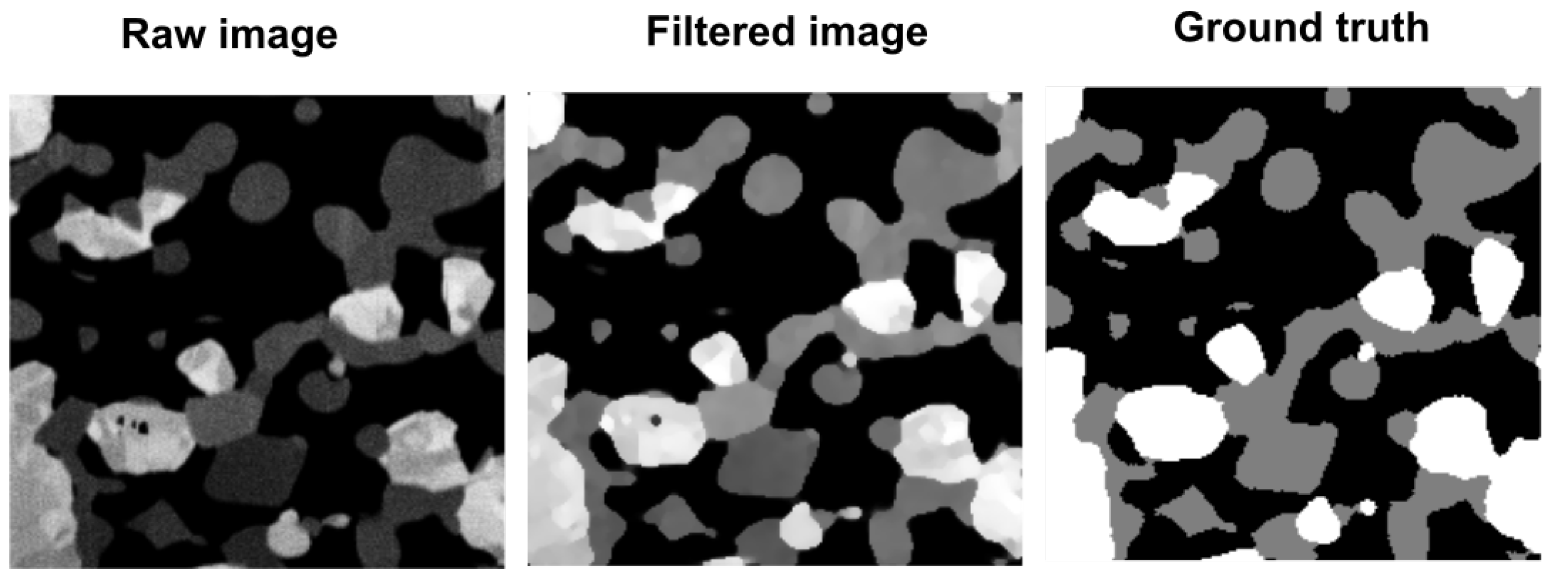
To present the effect of filtering on the FIB-SEM image, we show an example of an image after filtering juxtaposed with the original FIB-SEM image and the manually segmented image (ground truth). The exemplary results are presented in Figure 2. It can be seen that incorporating filtration does not distort the shape of each phase while improving intensity, homogeneity, and sharpness. Moreover, it can be seen that the manually segmented image has exaggerated Ni and YSZ phases which results in underestimation of the pore phase during manual segmentation. We note that filtering could help operators segment images after performing pure manual segmentation of several images from the sample.
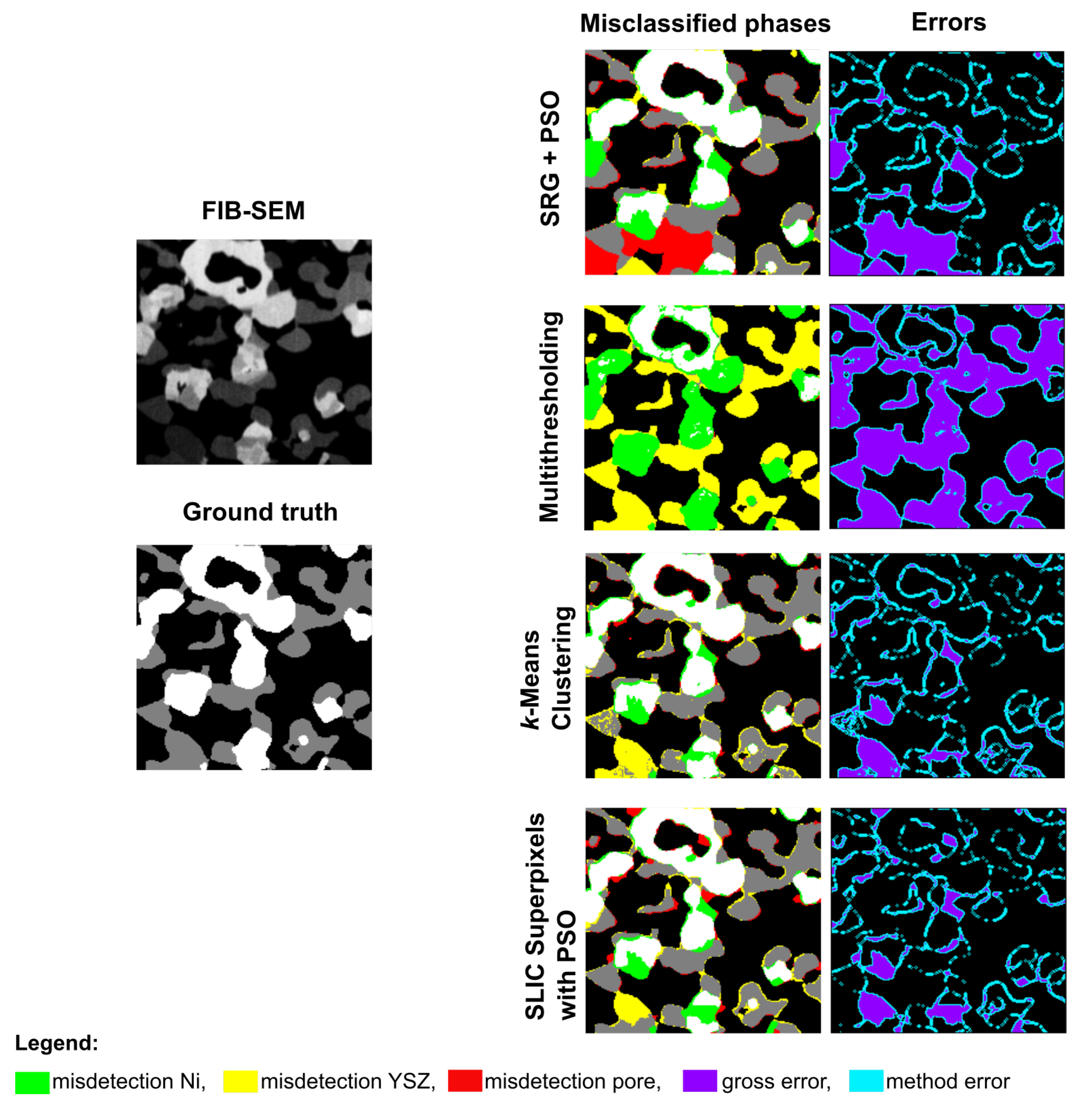
The segmented images were compared with the ground truth to investigate the impact of the proposed filtration on selected segmentation methods. The comparison was conducted in two steps. First, the exemplary results of segmentation were conducted by the selected methods on as-received micrographs and compared. Second, we applied the selected segmentation methods to already filtered images. The filtering was conducted by the proposed methodology. The results of the first comparison, without filtering applied, are presented in Figure 3. On the left-hand side, one can see an original FIB-SEM and a reference image, which is a manually segmented image that serves as the ground truth. On the column on the right-hand side, the images segmented by different methods are presented. Each image has a misclassified phase marked in different colors, where green corresponds to the misclassification of nickel, yellow to YSZ, and red are misclassified pores. Two types of errors were distinguished: gross error indicates the misclassification of a whole part of the phase area and method error, which concerns pixels on the edges of the phase and is related to the experience of the user performing manual segmentation. Those illustrative results indicate that all methods perform poorly on unprocessed images.
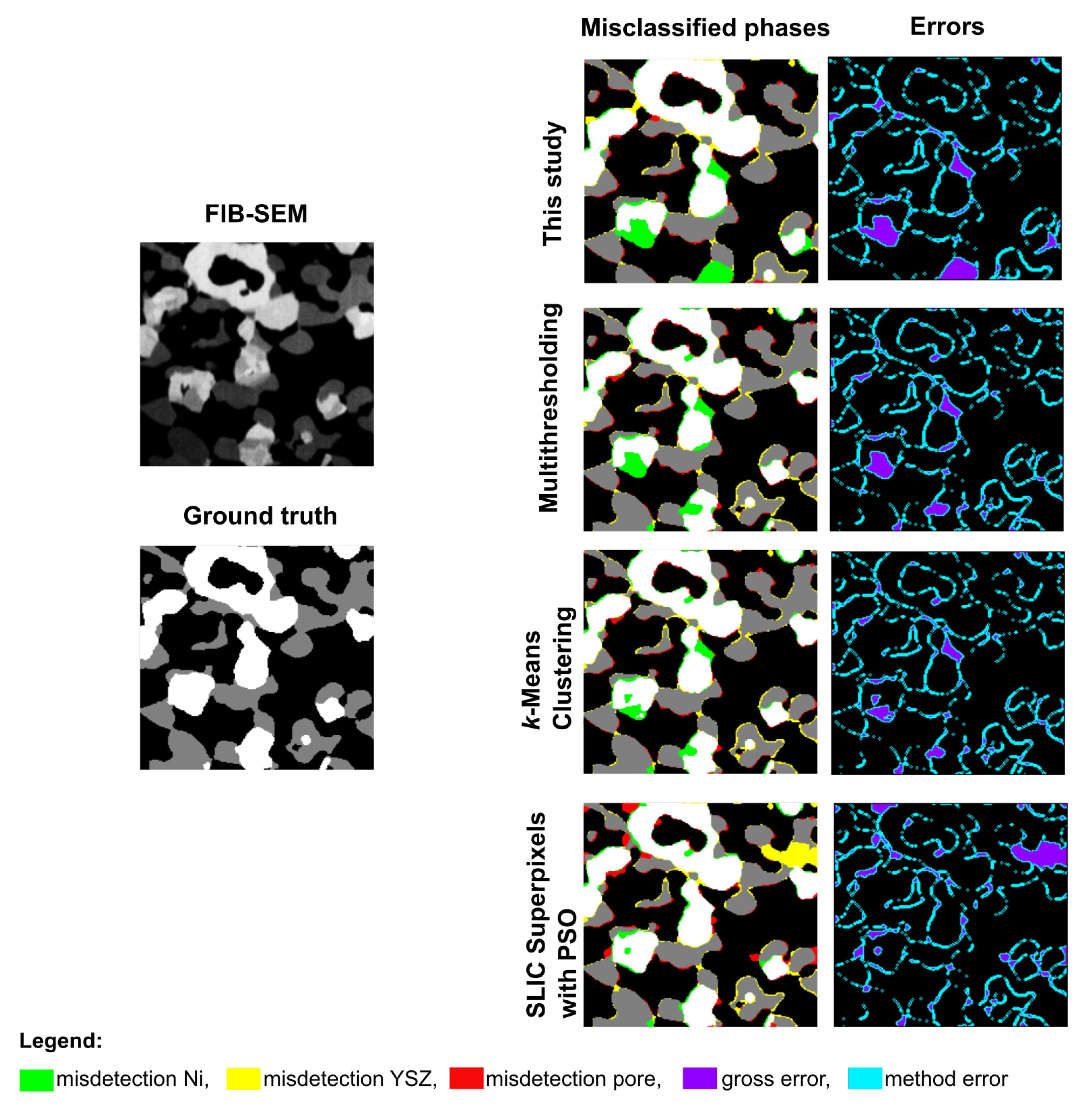
To investigate the impact of filtering on the quality of segmentation, we repeated the calculation for filtered images using SRG with PSO, Multithresholding, k-Means Clustering, and SLIC Superpixels with PSO algorithms. As shown in Figure 4, the filtration with PSO significantly decreased the misclassified regions in all used segmentation algorithms compared to the results presented in Figure 3.
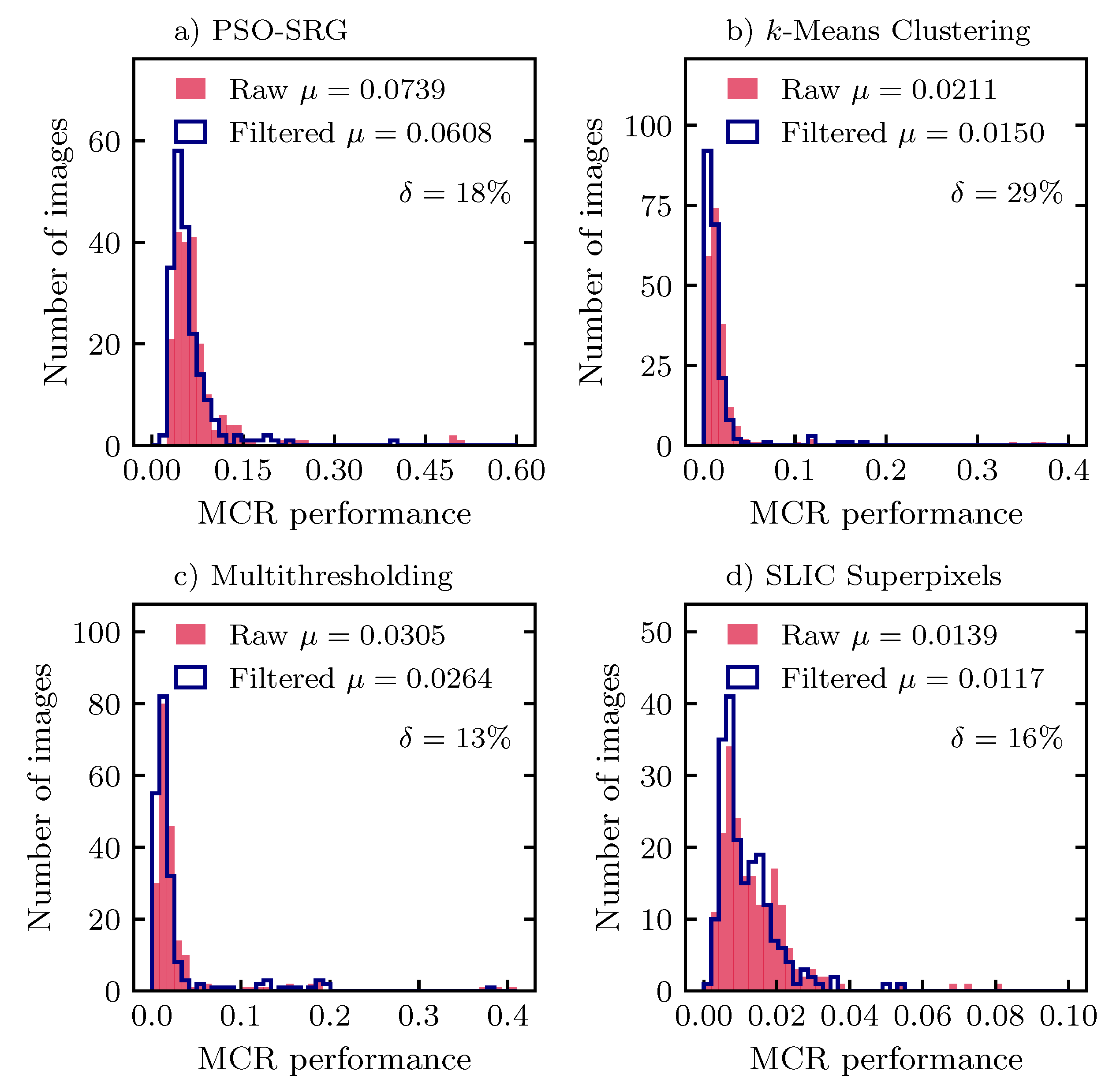
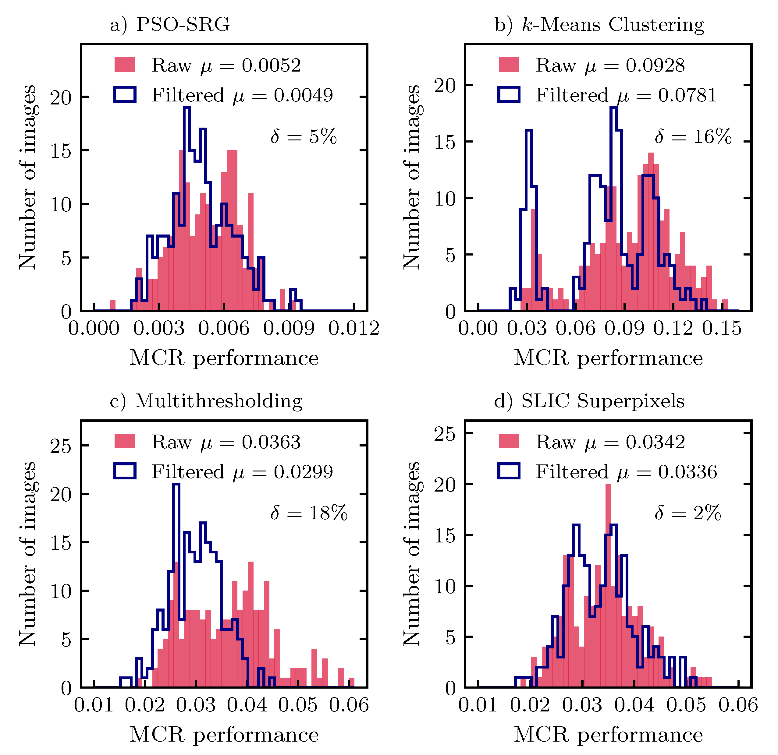
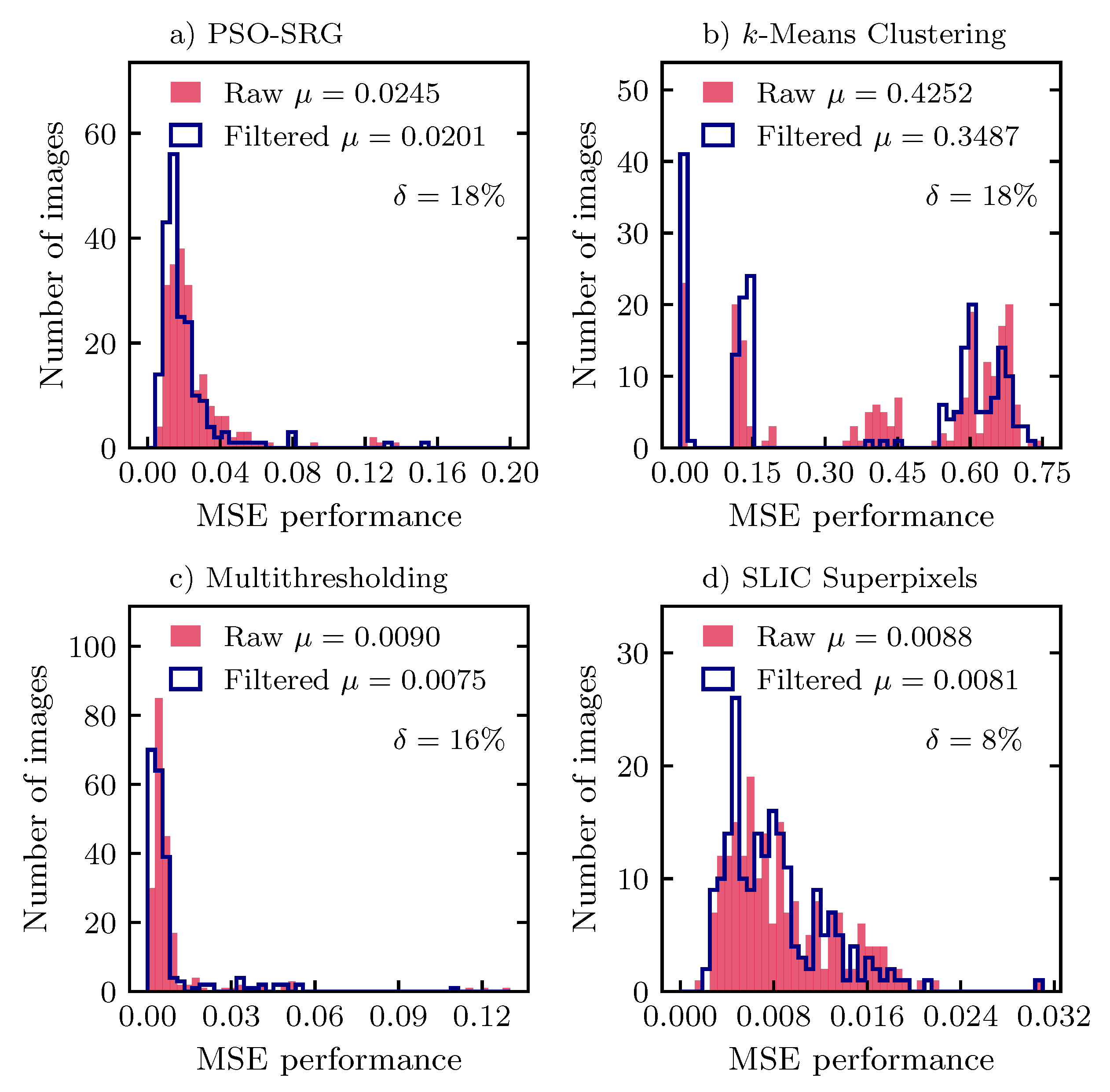
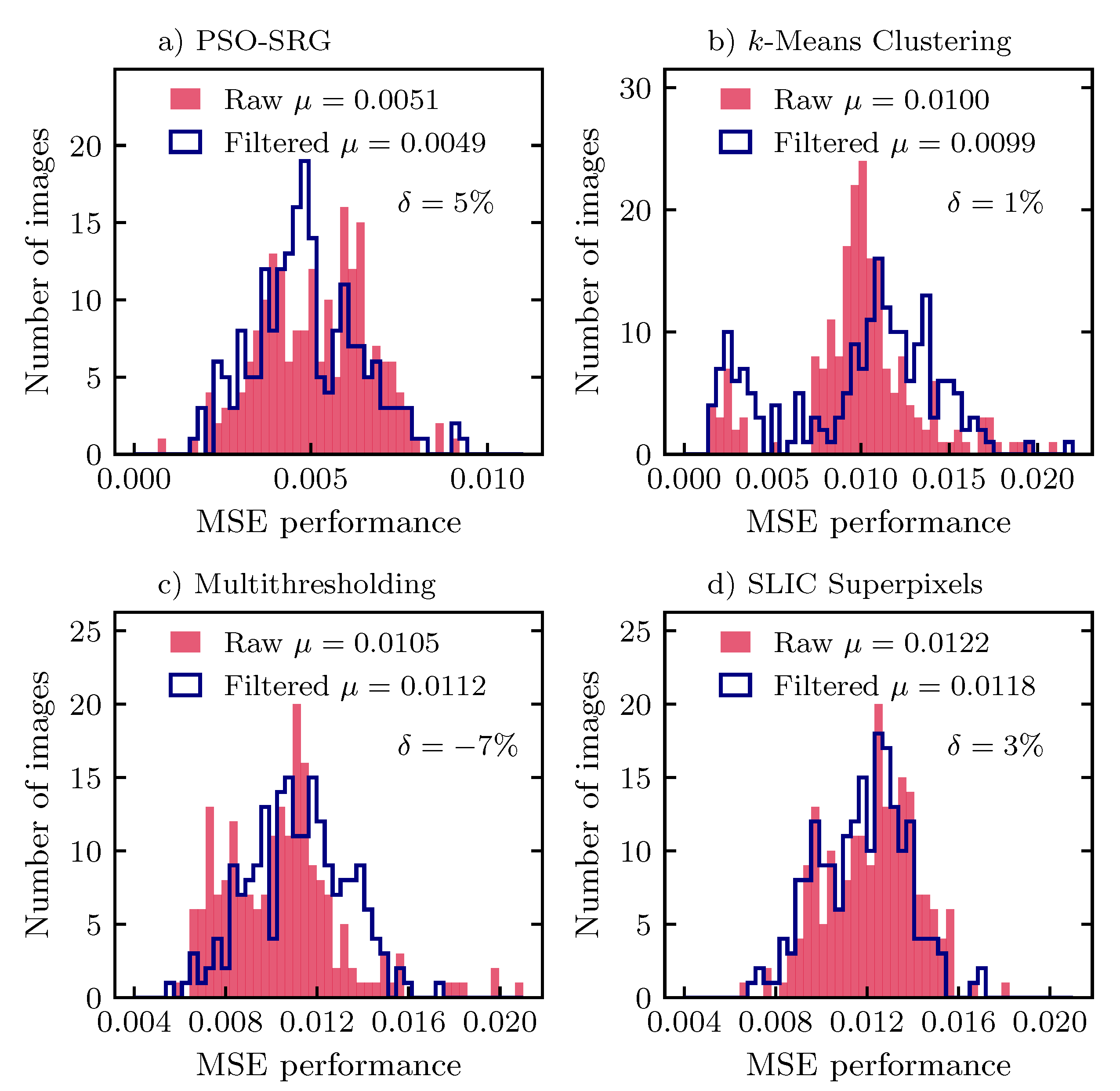
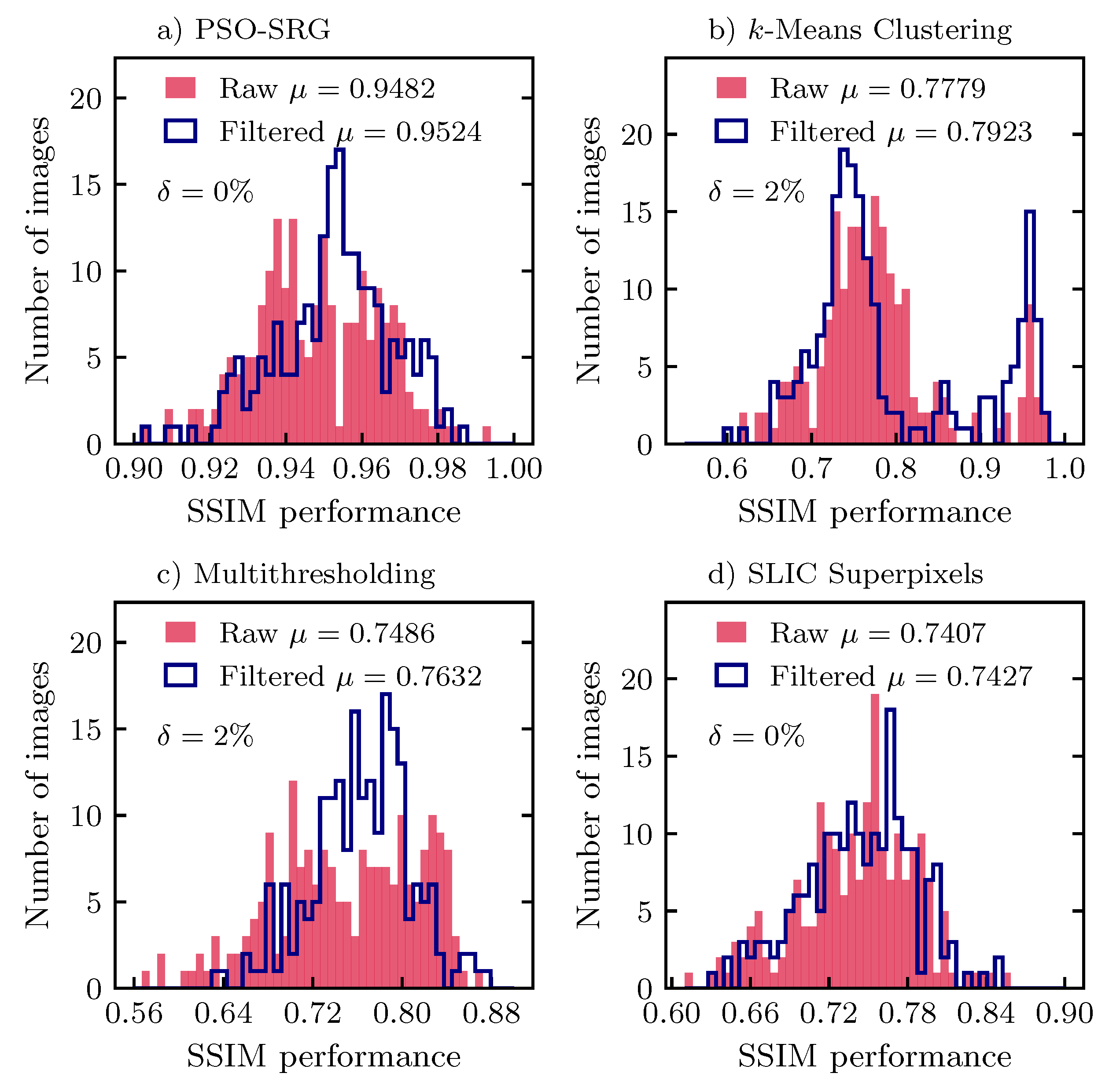
Because the presented results correspond only to one image, we performed a statistical analysis covering filtered and unfiltered images, various methods, and image evaluation metrics on 200 images. The segmentation methods’ performances were evaluated using various metrics to provide a comprehensive set of data regarding the quality of segmentation. Each metric offers different ways to assess image segmentation quality, so it is beneficial to employ more than one to avoid misleading results. The selected methods were the Misclassification Ratio (MCR) [49,50,51], Structural Similarity Index Measure (SSIM) [52,53] and Mean Squared Error (MSE) [52,54]. In the Figure 5, Figure 6, Figure 7, Figure 8, Figure 9 and Figure 10, we have juxtaposed the histograms for different metrics and segmentation methods conducted for images with and without filtering. Different figures correspond to different metrics and error types, subfigures to methods. On each subfigure, the x-axis shows the value of given metrics, and on the y-axis, a number of images with a given value range are presented. Distribution obtained by segmentation without filtering is represented by a light red filled color. Distribution obtained with the use of filtering is represented as a blue line. In the legend, the mean value of a metric is presented as the symbol μ . Relative change of the mean value of the given metrics is presented in each subfigure as the symbol δ .
In the Figure 5 we can see that for all methods, the MCR metric of gross error decreases after using filtering, between 13% for Multithresholding and 29% for k-Means Clustering. For method error presented in Figure 6, MCR values improve by 18% and 16% for Multithresholding and k-Means Clustering, correspondingly. For PSO-SRG and SLIC Superpixels, the improvement is a few times smaller than for the gross error, namely 5% and 2%, correspondingly. The MCR metric indicates that filtering improves the method’s performance significantly by reducing the gross error.
In the Figure 7, we can see that for all methods, the MSE metric of gross error decreases after filtering between 8% for SLIC Superpixels and 18% for k-Means Clustering and PSO-SRG. For the method error presented in the Figure 8, the metric value of Multithresholding decreases by 7% and increases between 1% and 5% for other methods. For all methods, aside from Multithresholding, it is a few times smaller than for gross error. The MSE metric, the same as the MCR, indicates that filtering improves the method’s performance significantly by reducing the gross error.
In the Figure 9 we can see that the SSIM metric improves highly for k-Means Clustering (80%) on a gross error after using filtering. For PSO-SRG and Multithresholding, the increase is small, 6% and 3%, correspondingly. For the method error presented in the Figure 10, metric value improvement of all methods is negligible. The SSIM metric indicates that filtering improves the k-Means Clustering method performance significantly by reducing the gross error.

4. Conclusions

In this paper, a supervised electron microscopy image segmentation methodology that uses Particle Swarm Optimization was introduced. In the procedure, the Particle Swarm Optimization algorithm effectively finds the optimal values of filters’ parameters and improves the overall quality of the obtained micrographs. The proposed methodology was validated with four different segmentation algorithms. Each algorithm was used to segment a batch of filtered and unfiltered images. Each time, a distribution of three different quality metrics MCR, SSIM, and MSE were obtained. The results indicated high improvement (8–29%) for all methods in MCR and MSE metrics, and 80% improvement in the SSIM metric for k-Means Clustering.
The potential application in three-phase identification of a SOFC anode microstructure was demonstrated. An important aspect is the possibility of modifying the filtering procedure by adding or removing filters that make it more specific for the particular problem, and using it as an independent process executed before any segmentation method in the future. The method’s main shortcoming is uneven illumination and shading in microscopy images. It causes incorrect initialization of seeds and affects further SRG processes. To obtain better segmentation results, the images might be segmented manually by different users and method errors might not be included in the machine learning process.

Author Contributions

Conceptualization, G.B.; Methodology, G.B., M.C.; Software, W.N., M.C.; Validation, W.N., M.C. and S.B.; Formal analysis, W.N., M.C. and S.B.; Investigation, W.N.; Resources, G.B.; Data curation, W.N.; Writing—original draft preparation, G.B., W.N.; Writing—review and editing, G.B., S.B.; Visualization, W.N. and S.B.; Supervision, G.B.; Project administration, G.B.; Funding acquisition, G.B. All authors have read and agreed to the published version of the manuscript.

Funding

The research was mainly conducted under the FIRST TEAM program by the Foundation for Polish Science co-funded by the European Union under the European Regional Development Fund (Grant No. FirstTEAM/2016-1/3). Additionally, the present work was partially supported by the PAN-JSPS Joint Research Project. The authors wish to additionally acknowledge the support of the Initiative for Excellence – Research University Project and AGH University of Science and Technology (Grant AGH no. 16.16.210.476) for this publication.

Institutional Review Board Statement

Not applicable.

Informed Consent Statement

Not applicable.

Data Availability Statement

The data available on a reasonable request.

Conflicts of Interest

The funders had no role in the design of the study; in the collection, analyses, or interpretation of data; in the writing of the manuscript, or in the decision to publish the results. The authors declare no conflicting interests.

Sample Availability

Samples of the compounds Ni/YSZ are available from the authors.

Abbreviations

The following abbreviations are used in this manuscript:
GDCGadolinium-Doped Ceria
FIBFocused Ion Beam
LSCFLanthanum Strontium Cobalt Ferrite
MCRMisClassification Ratio
MSEMean Squared Error
PSOParticle Swarm Optimization
ROIRegion Of Interest
SADSum of Absolute Differences
SEMScanning Electron Microscope
SLICSimple Linear Iterative Clustering
SOFCSolid Oxide Fuel Cell
SRGSeeded Region Growing
SSIMStructural Similarity Index Measure
YSZYttria-Stabilized Zirconia

References

  1. Pajak, M.; Buchaniec, S.; Kimijima, S.; Szmyd, J.S.; Brus, G. A multiobjective optimization of a catalyst distribution in a methane/steam reforming reactor using a genetic algorithm. Int. J. Hydrog. Energy 2020. in Press. [Google Scholar] [CrossRef]
  2. Tomiczek, M.; Kaczmarczyk, R.; Mozdzierz, M.; Brus, G. A numerical analysis of heat and mass transfer during the steam reforming process of ethane. Heat Mass Transf. 2017, 54, 2305–2314. [Google Scholar] [CrossRef]
  3. Pethaiah, S.S.; Sadasivuni, K.K.; Jayakumar, A.; Ponnamma, D.; Tiwary, C.S.; Sasikumar, G. Methanol Electrolysis for Hydrogen Production Using Polymer Electrolyte Membrane: A Mini-Review. Energies 2020, 13, 5879. [Google Scholar] [CrossRef]
  4. Prokop, T.; Berent, K.; Szmyd, J.S.; Brus, G. A Three-Dimensional Numerical Assessment of Heterogeneity Impact on a Solid Oxide Fuel Cell’s Anode Performance. Catalysts 2018, 8, 503. [Google Scholar] [CrossRef] [Green Version]
  5. Prokop, T.A.; Brus, G.; Kimijima, S.; Szmyd, J.S. Thin Solid Film Electrolyte and Its Impact on Electrode Polarization in Solid Oxide Fuel Cells Studied by Three-Dimensional Microstructure-Scale Numerical Simulation. Energies 2020, 13, 5127. [Google Scholar] [CrossRef]
  6. Brus, G.; Miyoshi, K.; Iwai, H.; Saito, M.; Yoshida, H. Change of an anode’s microstructure morphology during the fuel starvation of an anode-supported solid oxide fuel cell. Int. J. Hydrog. Energy 2015, 40, 6927–6934. [Google Scholar] [CrossRef]
  7. Iwai, H.; Shikazono, N.; Matsui, T.; Teshima, H.; Kishimoto, M.; Kishida, R.; Hayashi, D.; Matsuzaki, K.; Daisuke, K.; Motohiro, S.; et al. Quantification of SOFC anode microstructure based on dual beam FIB-SEM technique. J. Power Sources 2010, 195, 955–961. [Google Scholar] [CrossRef]
  8. Wilson, J.R.; Kobsiriphat, W.; Mendoza, R.; Chen, H.Y.; Hiller, J.M.; Miller, D.J.; Thornton, K.; Voorhees, P.W.; Adler, S.B.; Barnett, S.A. Three-dimensional reconstruction of a solid-oxide fuel-cell anode. Nat. Mater. 2006, 5, 541–544. [Google Scholar] [CrossRef]
  9. Joos, J.; Carraro, T.; Weber, A.; Ivers-Tiffee, E. Reconstruction of porous electrodes by FIB/SEM for detailed microstructure modeling. J. Power Sources 2011, 196, 7302–7307. [Google Scholar] [CrossRef]
  10. Prokop, T.A.; Berent, K.; Iwai, H.; Szmyd, J.S. A three-dimensional heterogeneity analysis of electrochemical energy conversion in SOFC anodes using electron nanotomography and mathematical modeling. Int. J. Hydrog. Energy 2018, 43, 10016–10030. [Google Scholar] [CrossRef]
  11. Wilson, J.R.; Gameiro, M.; Mischaikow, K.; Kalies, W.; Voorhees, P.W.; Barnett, S.A. Three-Dimensional Analysis of Solid Oxide Fuel Cell Ni-YSZ Anode Interconnectivity. Microsc. Microanal. 2009, 15, 71–77. [Google Scholar] [CrossRef] [PubMed] [Green Version]
  12. Kishimoto, M.; Iwai, H.; Saito, M.; Yoshida, H. Quantitative evaluation of solid oxide fuel cell porous anode microstructure based on focused ion beam and scanning electron microscope technique and prediction of anode overpotentials. J. Power Sources 2011, 196, 4555–4563. [Google Scholar] [CrossRef]
  13. Brus, G.; Iwai, H.; Sciazko, A.; Saito, M.; Yoshida, H.; Szmyd, J.S. Local evolution of anode microstructure morphology in a solid oxide fuel cell after long-term stack operation. J. Power Sources 2015, 288, 199–205. [Google Scholar] [CrossRef]
  14. Jiao, Z.; Shikazono, N. 3D reconstruction size effect on the quantification of solid oxide fuel cell nickel–yttria-stabilized-zirconia anode microstructural information using scanning electron microscopy-focused ion beam technique. Eng. Sci. 2016, 61, 1317–1323. [Google Scholar] [CrossRef] [Green Version]
  15. Bertei, A.; Ruiz-Trejo, E.; Kareh, K.; Yufit, V.; Wang, X.; Tariq, F.; Brandon, N.P. The fractal nature of the three-phase boundary—A heuristic approach to the degradation of nanostructured solid oxide fuel cell anodes. Nano Energy 2017, 38, 526–536. [Google Scholar] [CrossRef]
  16. Jorgensen, P.S.; Bowen, J.R. Automatic Quantitative Image Analysis of Micrographs. In Proceedings of the European SOFC and SOE Forum, Lucern, Switzerland, 3–6 July 2008. [Google Scholar]
  17. Mary, J.M. Image segmentation technique-a study on region growing approaches. Int. J. Sci. Res. Comput. Sci. 2017, 2, 7–10. [Google Scholar]
  18. Russ, J.C. The Image Processing Handbook, 5th ed.; CRC Press: Boca Raton, FL, USA, 2006. [Google Scholar] [CrossRef] [Green Version]
  19. Jorgensen, P.S.; Hansen, K.V.; Larsen, R.; Bowen, J.R. A framework for automatic segmentation in three dimensions of microstructural tomography data. Ultramicroscopy 2010, 110, 216–228. [Google Scholar] [CrossRef]
  20. Mozdzierz, M.; Berent, K.; Kimijima, S.; Szmyd, J.S.; Brus, G. A Multiscale Approach to the Numerical Simulation of the Solid Oxide Fuel Cell. Catalysts 2019, 9, 253. [Google Scholar] [CrossRef] [Green Version]
  21. Schindelin, J.; Arganda-Carreras, I.; Frise, E.; Kaynig, V.; Longair, M.; Pietzsch, T.; Preibisch, S.; Rueden, C.; Saalfeld, S.; Schmid, B.; et al. Fiji: An open-source platform for biological-image analysis. Nat. Methods 2012, 9. [Google Scholar] [CrossRef] [Green Version]
  22. Rueden, C.T.; Schindelin, J.; Hiner, M.C.; DeZonia, B.E.; Walter, A.E.; Arena, E.T.; Eliceiri, K.W. ImageJ2: ImageJ for the next generation of scientific image data. BMC Bioinform. 2017, 18, 1–26. [Google Scholar] [CrossRef]
  23. Sciazko, A.; Komatsu, Y.; Shimura, T.; Shikazono, N. Segmentation of Solid Oxide Cell Electrodes by Patch Convolutional Neural Network. J. Electrochem. Soc. 2021, 168, 044504. [Google Scholar] [CrossRef]
  24. Law, T.Y.; Heng, P. Automated extraction of bronchus from 3D CT images of lung based on genetic algorithm and 3D region growing. Proc. SPIE 2000, 3979, 906–916. [Google Scholar] [CrossRef]
  25. Whitney, B.W.; Backman, N.J.; Furst, J.D.; Raicu, D.S. Single click volumetric segmentation of abdominal organs in Computed Tomography images. Proc. SPIE 2000, 6144, 61444G-1. [Google Scholar] [CrossRef] [Green Version]
  26. Feng, Q.; Gao, B.; Lu, P.; Woo, W.; Yang, Y.; Fan, Y.; Qiu, X.; Gu, L. Automatic seeded region growing for thermography debonding detection of CFRP. NDT E Int. 2018, 99, 36–49. [Google Scholar] [CrossRef]
  27. Yang, X.; Fu, X.; Li, X. Adaptive Clustering SOFC Image Segmentation Based on Particle Swarm Optimization. IOP Conf. Ser. J. Phys. 2020, 1229, 18859–18881. [Google Scholar] [CrossRef]
  28. Fu, X.; Yang, X.; Guo, C.; Li, X. Noise suppressed and bias field corrected image segmentation method for porous Ni-YSZ anode microstructure. Multimed. Tools Appl. 2020, 79, 012020. [Google Scholar] [CrossRef]
  29. Eberhart, R.; Kennedy, J. A new optimizer using particle swarm theory. In Proceedings of the Sixth International Symposium on Micro Machine and Human Science, Nagoya, Japan, 4–6 October 1995; pp. 39–43. [Google Scholar] [CrossRef]
  30. Kachitvichyanukul, V. Comparison of Three Evolutionary Algorithms: GA, PSO, and DE. Ind. Eng. Manag. Syst. 2012, 11, 215–223. [Google Scholar] [CrossRef] [Green Version]
  31. Lech, S.; Kruk, A.; Gil, A.; Cempura, G.; Agüero, A.; Czyrska-Filemonowicz, A. Three-dimensional imaging and characterization of the oxide scale formed on a polycrystalline nickel-based superalloy. Scr. Mater. 2019, 167, 16–20. [Google Scholar] [CrossRef]
  32. Jiao, Z.; Shikazono, N.; Kasagi, N. Quantitative characterization of SOFC nickel-YSZ anode microstructure degradation based on focused-ion-beam 3D-reconstruction technique. J. Electrochem. Soc. 2012, 159, B285–B291. [Google Scholar] [CrossRef]
  33. Sciazko, A.; Miyahara, K.; Komatsu, Y.; Shimura, T.; Jiao, Z.; Shikazono, N. Influence of Initial Powder Morphology on Polarization Characteristics of Nickel/Gadolinium-Doped-Ceria Solid Oxide Fuel Cells Electrode. J. Electrochem. Soc. 2019, 166, F44–F52. [Google Scholar] [CrossRef]
  34. Brus, G.; Iwai, H.; Szmyd, J.S. An Anisotropic Microstructure Evolution in a Solid Oxide Fuel Cell Anode. Nanoscale Res. Lett. 2020, 15, 427. [Google Scholar] [CrossRef]
  35. Wang, A.Z.; Bovik, H.C.; Sheikh, R.; Simoncelli, E.P. Image quality assessment: From error visibility to structural similarity. IEEE Trans. Image Process. 2004, 13. [Google Scholar] [CrossRef] [PubMed] [Green Version]
  36. Hast, A.; Marchetti, A. Improved illumination correction that preserves medium-sized objects. Mach. Graph. Visions 2014, 23, 3–20. [Google Scholar]
  37. Canny, J. A Computational Approach to Edge Detection. IEEE Trans. Pattern Anal. Mach. Intell. 1986, PAMI-8, 679–698. [Google Scholar] [CrossRef]
  38. The MathWorks, Inc. Adjust Image Intensity Values or Color Map. 2020. Available online: https://www.mathworks.com/help/images/ref/imadjust.html (accessed on 25 August 2020).
  39. Hast, A.; Marchetti, A. Retrospective Illumination Correction of Greyscale Historical Aerial Photos. Image Anal. Process. Notes Comput. Sci. 2011, 6979. [Google Scholar] [CrossRef] [Green Version]
  40. Barnes, A. Kuwahara Filter. MATLAB Central File Exchange. Available online: https://www.mathworks.com/matlabcentral/fileexchange/8171-kuwahara-filter (accessed on 25 August 2020).
  41. Papari, G.; Petkov, N.; Campisi, P. Artistic Edge and Corner Enhancing Smoothing. IEEE Trans. Image Process. 2007, 16, 2449–2461. [Google Scholar] [CrossRef] [Green Version]
  42. Agarwal, R. Homomorphic Filter Using Matlab. Available online: http://thelearningsquare.in/image-processing/ (accessed on 25 August 2020).
  43. The MathWorks, Inc. Sharpen Image Using Unsharp Masking. 2020. Available online: https://www.mathworks.com/help/images/ref/imsharpen.html (accessed on 25 August 2020).
  44. The MathWorks, Inc. 2-D Gaussian Filtering of Images. 2020. Available online: https://www.mathworks.com/help/images/ref/imgaussfilt.html (accessed on 25 August 2020).
  45. Pätz, T. Segmentation of Stochastic Images Using Stochastic Partial Differential Equations. Ph.D. Thesis, Jacobs University, Bremen, Germany, 2012. [Google Scholar]
  46. Adams, R.; Bischof, L. Seeded region growing. IEEE Trans. Pattern Anal. Mach. Intell. 1994, 16, 641–647. [Google Scholar] [CrossRef] [Green Version]
  47. Hore, S.; Chakraborty, S.; Chatterjee, S.; Dey, N.; Ashour, A.S.; Chung, L.V.; Le, D.N. An Integrated Interactive Technique for Image Segmentation using Stack based Seeded Region Growing and Thresholding. Int. J. Electr. Comput. Eng. (IJECE) 2016, 6, 2773–2780. [Google Scholar] [CrossRef]
  48. Mehnert, A.; Jackway, P. An improved seeded region growing algorithm. Pattern Recognit. Lett. 1997, 18, 1065–1071. [Google Scholar] [CrossRef]
  49. Fu, X.; Xiang, Y.; Chen, L.; Xu, X.; Li, X. A Novel Ni/YSZ Anode Image Segmentation Method for Solid Oxide Fuel Cell Electrodes Microstructure. Fuel Cells 2016, 16, 810–816. [Google Scholar] [CrossRef]
  50. Hu, C.; Fan, W.; Du, J.; Yuchen, Z. Model-Based Segmentation of Image Data Using Spatially Constrained Mixture Models. Neurocomputing 2017, 283, 1–14. [Google Scholar] [CrossRef]
  51. Bankman, I.N. (Ed.) Handbook of Medical Image Processing and Analysis, 2nd ed.; Academic Press: Burlington, MA, USA, 2009. [Google Scholar]
  52. Al-Najjar, Y.; Der Chen, S. Comparison of image quality assessment: PSNR, HVS, SSIM, UIQI. Int. J. Sci. Eng. Res. 2012, 3, 176–183. [Google Scholar]
  53. Wang, Z.; Shang, X. Spatial pooling strategies for perceptual image quality assessment. In Proceedings of the IEEE International Conference on Image Processing, Atlanta, GA, USA, 8–11 October 2006; pp. 8–11. [Google Scholar]
  54. Shaaban, H.R.M.; Habib, A.A.; Obaid, F.A. Performance Evaluation of K-Mean and Fuzzy C-Mean Image Segmentation Based Clustering Classifier. Int. J. Adv. Comput. Sci. Appl. 2015, 6, 176–183. [Google Scholar]
Samples of the compounds Ni/YSZ are available from the authors.
Figure 1. Schematic view on solid oxide fuel cell and microstructure of the anode and the cathode.
Energies 14 03055 g001
Figure 2. Example of filtration performed on a raw FIB-SEM image juxtaposed with an image segmented by the operator.
Energies 14 03055 g002
Figure 3. Segmentation results of different algorithms, SLIC Superpixels with PSO, k-Means Clustering, Multithresholding and proposed SRG with PSO, for the exemplary raw SEM image (200 × 200 px) without filtering applied. Manually segmented image taken as a ground truth.
Energies 14 03055 g003
Figure 4. Segmentation results of different algorithms, SLIC Superpixels with PSO, k-Means Clustering, Multithresholding and proposed SRG with PSO, for the exemplary raw SEM image (200 × 200 px) with PSO-aided filtering applied. Manually segmented image taken as a ground truth.
Energies 14 03055 g004
Figure 5. MCR performance on gross error only histograms for (a) PSO-SRG, (b) k-Means Clustering, (c) Multithresholding, and (d) SLIC Superpixels based on a sample of 200 images.
Energies 14 03055 g005
Figure 6. MCR performance on method error only histograms for (a) PSO-SRG, (b) k-Means Clustering, (c) Multithresholding, and (d) SLIC Superpixels based on a sample of 200 images.
Energies 14 03055 g006
Figure 7. MSE performance on gross error only histograms for (a) PSO-SRG, (b) k-Means Clustering, (c) Multithresholding, and (d) SLIC Superpixels based on a sample of 200 images.
Energies 14 03055 g007
Figure 8. MSE performance on method error only histograms for (a) PSO-SRG, (b) k-Means Clustering, (c) Multithresholding, and (d) SLIC Superpixels based on a sample of 200 images.
Energies 14 03055 g008
Figure 9. SSIM performance on gross error only histograms for (a) PSO-SRG, (b) k-Means Clustering, (c) Multithresholding, and (d) SLIC Superpixels based on a sample of 200 images.
Energies 14 03055 g009
Figure 10. SSIM performance on method error only histograms for (a) PSO-SRG, (b) k-Means Clustering, (c) Multithresholding, and (d) SLIC Superpixels based on a sample of 200 images.
Energies 14 03055 g010
Table 1. Composition of anode suspension on an experimental SOFC button cell.
ConstituentProducerContent [wt.%]
NiO powderfuelcellmaterials, USA35.6
YSZ powderTosoh, Japan31.1
PVBSigmaAldrich, USA3.3
PEGSigmaAldrich, USA10.0
Toluene/Ethanol (60/40 vol.%)POCH, Poland20.0
Table 2. List of filters, parameters and parameters’ allowed values.
FilterParameterRanges
Adjust image intensity values [38]gamma correction = 1 (default)
Illumination correction [39]correction factor0.001–5
Kuwahara [40,41]window size1–7
Homomorphic [42]order of the Butterworth highpass filter0.001–300
cutoff distance0.001–25
Edge preservingUnsharp masking [43]standard deviation of the Gaussian lowpass filter0.001–25
filter strength0.001–25
Gaussian smoothing [44]standard deviation0.001–25
Table 3. Optimized filters’ parameters.
FilterParameterValue
Illumination correction [39]correction factor0.033
Kuwahara [40,41]window size1.03
Homomorphic [42]order of the Butterworth highpass filter0.001
cutoff distance0.001
Unsharp masking [43]standard deviation of the Gaussian lowpass filter24.959
filter strength0.001
Gaussian smoothing [44]standard deviation1.241
Table 4. Optimized SRG thresholds.
PhaseWith FiltrationWithout Filtration
Nickel0.0880.082
Pore0.0420.008
YSZ0.1270.091
Publisher’s Note: MDPI stays neutral with regard to jurisdictional claims in published maps and institutional affiliations.