Article

A Finite-Time Robust Distributed Cooperative Secondary Control Protocol for Droop-Based Islanded AC Microgrids

1
Department of Electrical and Computer Engineering, COMSATS University Islamabad, Abbottabad Campus, Abbottabad 22060, Pakistan
2
Department of Electrical Engineering, University of Engineering and Technology Peshawar, Bannu Campus, Bannu 28100, Pakistan
3
Department of Electrical and Computer Engineering, COMSATS University Islamabad, Islamabad 45550, Pakistan
4
Department of Electrical and Computer Engineering, Faculty of Engineering and Applied Sciences, Memorial University of Newfoundland, St. John’s, NL A1B 3X5, Canada
5
School of Electrical Engineering, National University of Computer and Emerging Sciences Islamabad, Islamabad 45550, Pakistan
*
Author to whom correspondence should be addressed.
Energies 2021, 14(10), 2936; https://doi.org/10.3390/en14102936
Submission received: 10 April 2021 / Revised: 30 April 2021 / Accepted: 14 May 2021 / Published: 19 May 2021

Abstract

:
In this research work, a resilient finite-time consensus-based distributed secondary control protocol is presented for droop-based distributed generating (DG) units of an islanded AC microgrid (MG). Through a multi-agent control structure, the DG units of the microgrid adjust their active power outputs so that they reach an agreed-upon value in a finite time. Concurrently, all the DG units are forced to operate with their frequencies regulated to the reference MG frequency in a finite time, despite time-varying load perturbations. Each DG unit is provided with a hierarchical control architecture, where the primary control is achieved using the droop control method, while the secondary control is established through the proposed distributed control protocol. The communication between DG units takes place over a sparse communication network. The proposed control protocol is robust to both small and sufficiently large communication latencies and it supports the plug-and-play feature of DG units. Different time-domain-based numerical simulations are carried out on a small as well as large microgrid testbenches in Matlab/Simulink and demonstrate the correctness and effectiveness of the proposed distributed control protocol. A comparative study is also presented with the existing distributed control protocol, and it is found that the proposed strategy is superior in its performance.

1. Introduction

The pioneering concept of microgrids (MGs) was presented by Robert H. Lasseter in 2001/2002. He stated that a MG is a low-voltage power system that consists of a cluster of micro-generation sources (MGSs) or distributed generating (DG) units, energy storage systems (ESSs) and loads. It appears to the main grid as a single controllable entity, operable in either mode (i.e., grid-tied or autonomous mode), and provides both electric power and heat locally [1,2,3,4]. The existence of a flexible but controllable interface between the main grid and the MG is the heart of the MG concept. A grid-connected MG has a Point of Common Coupling (PCC) or Point of Interconnection (POI) as an interfacing point with the main grid/large power system [5,6]. This interface essentially provides electrical isolation between the MG and the main grid, but also connects them economically. To the customers, the MG can be designed to appear as a low-voltage, small autonomous power system that is capable of functioning optimally to meet the various requirements of customers, such as local voltage support, enhanced reliability, reduced feeder losses, enhanced efficiency through waste heat recovery and quality of power (i.e., providing uninterruptible power supply, voltage sag correction to name a few). To the main grid, however, the MG can be designed to appear as a good or even a model citizen. It can be regarded as a controlled cell of the main power system that can be controlled as a single dispatchable load. Furthermore, it can respond very quickly to fulfill the requirements of the transmission system [1,2].
MGSs are of special interest for MGs, which are low-voltage, low-cost, small generating units with power electronic interfaces. These sources can be renewable energy or non-renewable energy-based, and their prime movers typically include wind turbines, photovoltaic modules, fuel cells, microturbines, gas turbines, internal combustion (IC) engines, etc., which are placed at the customers’ sites [2,6]. The power electronics interface provides the control and flexibility needed by the MG concept. Properly designed power electronics interfaces and controls would ensure that the MG meets its customers’ as well as the main grid’s demands [7]. In the autonomous mode of the MG, a load-tracking problem may arise owing to the inertia-less nature (i.e., slow response time) of some MGSs, such as fuel cells and microturbines. Thus, the MG must be provided with some sort of energy storage to ensure an initial energy balance in the autonomous mode. It is worthwhile to state that, in present power systems, energy storage is provided by emulating the inertia of synchronous generators. When the system load increases, the initial energy balance is provided by the system’s inertia, resulting in a slight reduction of the system’s frequency [2]. The requisite energy storage for an MG comes in several different forms, such as batteries, flywheels, supercapacitors/ultracapacitors or traditional generation with inertia [2,7].
To ensure the operational stability, reliability and optimality of the MG, it is provided with a set of software and hardware that constitutes the MG control system. This control system is divided into three levels: primary, secondary and tertiary. The key functions of the MG control system include (i) maintaining the frequency, voltage and current within a desired range, (ii) keeping a balance between power supply and demand, (iii) performing demand-side management and economic load dispatch and (iv) ensuring a smooth/seamless transition between various modes of operation [8,9]. Each control hierarchy is designed to achieve specific objectives and operates with different execution rates. Primary control is accountable for active/reactive power sharing at the cost of frequency/voltage deviations, respectively, and is implemented as a droop control or a similar control technique. Secondary control is accountable for restoring the frequency/voltage deviations caused by the primary control, and tertiary control is accountable for managing the power flow between the main grid and the MG [10]. The MG is intended to operate in the grid-connected mode under normal conditions. In this mode, the main grid plays the role of a frequency and voltage dictator, meaning that the MG has to synchronize its frequency and voltage to the main grid. Nonetheless, it can also be operated in the autonomous mode under the condition of some pre-planned maintenance or unplanned disturbance/fault. Once islanded, the primary control level keeps the frequency and voltage of the MG stable by keeping these values in pre-specified ranges [11,12,13,14]. However, it might not fully regulate the MG frequency and voltage; thus, an additional control level is needed to restore the frequency and voltage to the desired values. This functionality is provided by the secondary control level, which compensates for the frequency and voltage deviations caused by the primary control. The execution rate of the secondary control level is longer than the primary control. This in turn facilitates the design and decoupled operation of the two control levels [15,16,17,18].
The secondary control methods that accomplish the seamless transition of the MG from one mode to another are broadly classified into three main categories: (a) centralized (b) decentralized and (c) distributed control methods [10]. Conventionally, secondary control has been implemented as a single centralized controller, in which all the energy nodes are connected to one another and to the central control unit through bidirectional communication links to gather system-wide information. These communication links increase the cost and decrease the reliability of the MG. Centralized control ensures low-voltage performance through capability, accurate power sharing, etc., but is prone to a single point of failure; that is, if the central controller or one of the communication links fails, it causes the entire MG to collapse. Furthermore, this strategy places a large computational burden on the central controller, thus making its design complex and costly [18,19]. The decentralized control method comprises several individual controllers that need only local measurements, but it does not require a high-bandwidth communication infrastructure (except for synchronization purpose). Thus, it is proven to be more reliable than the centralized strategy because of its limited communication infrastructure [10,20]. However, due to the lack of system-wide information, all the available energy sources in an MG cannot be efficiently harmonized in an optimum way [21]. To counteract the stated limitations of the two control strategies, the distributed control method has been proven to be very reliable [18,21]; it is influenced by the idea of a multi-agent system (MAS). In this method, the energy nodes are considered to be agents that can exchange information with their neighboring nodes through a sparse communication infrastructure. Consequently, the cost of the communication infrastructure decreases and the system reliability increases [22].
Over the past few decades, there has been a remarkable progress in MAS-based distributed cooperative control strategies [23,24,25]. For this reason, the secondary control of MGs using distributed cooperative control techniques has attracted a great deal of attention from researchers. The authors in [26] reported a distributed consensus-based control strategy for an islanded AC microgrid with multiple droop-controlled DG units. The technique has been found to be useful for regulating the voltages, frequencies and active/reactive power outputs of the DG units. Furthermore, it has been tested and found to be successful during both constant and varying communication topologies along with time-varying communication latencies. The system closed-loop response has been found to exhibit more oscillations, or even become unstable, if the communication latency increases beyond a certain extent, as discussed in [18]. To address the actuator faults, in an islanded AC microgrid with switching communication topology, a distributed cooperative fault-tolerant control technique was reported in [27]. In [28], a detailed survey was conducted to signify the impact of communication latencies on the secondary frequency regulation in the case of islanded AC microgrids. It was found that the communication latency margin varied in direct proportion with the proportional gain value, but it varied inversely with the integral gain value of the secondary frequency controller. To counteract the effect of the communication latency, a gain scheduling strategy was adopted. The authors in [22] presented a robust finite-time distributed control protocol for the secondary frequency and voltage regulation of an islanded AC microgrid. The proposed strategy was successfully applied to offer a plug-and-play attribute in the DG units and increase the robustness to unmodeled system dynamics and parametric uncertainties. In [18], a robust consensus-based secondary frequency and voltage restoration strategy was applied to an IEEE 14-bus system based islanded AC microgrid. The performance of the stated technique was found to be superior to the feedback linearization-based distributed cooperative secondary control of microgrids presented in [29], in terms of successfully dealing with a frequently switching communication graph, load perturbations, parametric uncertainties, communication latencies and the plug-and-play feature of the DG units. Due to the nonlinear and non-identical nature of the DG units dynamics, an input–output feedback linearization method was used to transform the dynamics to linear in [29]. Nonetheless, the dynamics of the primary controller were ignored during this process, which might have reduced the functionality and stable operation of the microgrid. In another attempt, the same authors presented a distributed cooperative control framework for secondary voltage and the frequency restoration of inverter-based MGs in [30]. However, the schemes presented in [29,30] were not fully-distributed. To address the stated problem, a fully-distributed (also termed as distributed adaptive) consensus-based control strategy was reported in [31] for droop-based islanded AC microgrids. For the resilient operation of an autonomous microgrid comprising inverter-based DG units, a fast terminal sliding mode-based distributed secondary voltage control strategy was proposed in [32]. A Kalman–Bucy filter-based extended state observer was designed for accurate estimation of the state information of the extended DG model and counteract the disturbances resulting from three different sources: measurement noise, parameter variation and immeasurable external variables. However, there may exist intentional and external interferences, such as cyber attacks and communication faults; thus, furthermore exploration is required for extending this work to handle the problem of cybersecurity-based MG control design. The authors in [33] proposed a cooperative secondary voltage control scheme for autonomous microgrids using an auxiliary centralized event-triggering controller. The event triggering controller was designed to generate the triggering time. In this scheme, the estimates of the agents were used to replace their actual values for feedback control. All the agents received the same event-triggering time from the auxiliary centralized controller. Thus, the communication between agents was only needed when the events were triggered. This strategy greatly reduced the burden of the communication network and enhanced the reliability of the control structure. However, due to the centralized event-triggering mechanism, this scheme was not fully distributed. In [34], the authors presented a probabilistic index to measure the controllability of currents and voltages in various lines and buses of both single- and multi-microgrid distribution systems. After that, the current-voltage controllability index was investigated for a pre-designed multi-microgrid system having an optimum reliability and supply-security. It was revealed that the controllability index was significantly low and could be improved. Finally, a novel comprehensive index was defined to optimally cluster an active distribution system into a multi-microgrid system having optimum reliability, supply security, and controllability.

Key Contributions

The key contributions made by this article are outlined as follow:
  • A resilient fully-distributed consensus-based secondary control protocol is designed for a droop-based islanded AC microgrid. The proposed design adjusts the real power outputs of the DG units so that they reach an agreed upon level in a finite time. Concurrently, all the DG units are forced to operate with their frequencies regulated to the reference microgrid frequency in a finite time, despite time-varying load perturbations. It is important to mention that the proposed strategy considers mixed types of DG units (i.e., both high-inertia and low-inertia types), whereas the techniques reported in [35,36,37] consider only low-inertia type DG units;
  • The uniqueness of the proposed design lies in the fact that the active power as well the frequency control of each DG unit is ensured through the application of the same control strategy at each DG unit, while the existing strategies reported in [35,36,37] apply a separate control protocol for real power and frequency regulation, thus requiring more control effort;
  • The proposed protocol is fully-distributed in the sense that each agent of the communication network only requires information regarding itself and its neighbors. This virtue directly helps in minimizing the overall bandwidth requirement. As a result, the microgrid can operate with greater reliability and flexibility, as compared to the strategies reported in [29,30], which were not fully-distributed;
  • The proposed scheme is robust to much higher communication latencies of around 1 s , whereas the strategies reported in [35,36,37] considered smaller communication latencies of around 16 m s and have not been tested for higher latencies. Furthermore, the proposed strategy guarantees plug-and-play capability for DG units.
The article is structured as follows. The preliminary graph theory is explained in Section 2. The mathematical modeling of the micro-generation sources of the test microgrid is presented in Section 3. Section 4 covers the proposed distributed finite-time consensus protocol design. In Section 5, the correctness and efficacy of the proposed distributed control protocol is verified through time-domain-based numerical simulations in Matlab/Simulink, while Section 6 summarizes the concluding remarks to this article.

2. Graph Theory

The concept of distributed control is based on the theory of the MAS, which considers an MG as a MAS, the energy nodes as vertices or agents and the communication links as arcs or edges. The information exchange/communication between various nodes takes place through a sparse communication system. The communication topology for a network of N nodes can be represented by a weighted graph, G ( E , V , A ) , whether directed (i.e., unidirectional) or undirected (i.e., bidirectional), where V = { 1 , 2 , , N } and E and A are, respectively, the set of vertices, the set of edges and the weighted adjacency matrix. The elements of the set E are denoted as ( i , j ) , which denotes an edge leaving the ith node and arriving at the jth node and is shown by an arrow with its tail at the ith node and head at the jth node. This implies that information can flow from the ith node to the jth node. The jth node can be regarded as a neighbor of the ith node if ( i , j ) E . The weight of the edge ( i , j ) is denoted by a i j , where a i j > 0 , if ( i , j ) E ; otherwise, it is 0. In other words, the edge ( i , j ) can be considered as outgoing with respect to the ith node and incoming with respect to the jth node and, in this case, the ith node is termed as the parent and the jth node as the child. The number of edges with the ith node as a head is termed as the in-degree, d i i n , of the ith node, while the number of edges with the ith node as a tail is termed as the out-degree, d i o u t , of the ith node. The neighboring set of nodes of the ith node is denoted by N i = { j V | ( j , i ) E } ; that is, the set of nodes with their edges arriving at the ith node. The number of neighbors of the ith node, | N i | , equals its in-degree, d i i n . If d i i n = d i o u t for all nodes, i V , the graph is termed as balanced. If ( i , j ) E = ( j , i ) E , and a i j = a j i , i , j , the graph is termed as undirected; otherwise, it is termed as a digraph or directed graph. The ith node is said to be connected to the jth node if there exists a directed path from the ith node to the jth node. A digraph is termed as strongly connected if there is a directed path between every two distinct nodes. On the other hand, an undirected graph is termed as simply connected if there is an undirected path between every two distinct nodes.
By examining the properties of the Laplacian, adjacency and in-degree matrices (i.e., L, A and D, respectively), the graph structure and properties can be determined. For the ith node, the weighted Laplacian matrix is defined as follows [38,39]:
L i j R N × N where i j a i j i j d i i n = j N i a i j i = j
An alternative method for determining the Laplacian matrix uses L = D A , where
A a i j R N × N where a i j > 0 i j 0 i = j
D diag d i i n where d i i n = j N i a i j i = j

3. Mathematical Modeling of Micro-Generation Sources

The correctness and effectiveness of the proposed control technique is evaluated by using a three-phase microgrid (MG) testbench, as illustrated in Figure 1. Note that the dotted arrows represent the undirected communication between the distributed generating (DG) units. The stated MG has three DG units and four buses. Two of the DG units are inverter-based (i.e., a microsource (MS) and an external energy storage system (ESS)). The third DG unit comprises an internal combustion (IC) engine operated diesel genset (GS) with a wound-field synchronous generator. The order of connection of the ESS, MS and GS to the buses, respectively, is 1, 3 and 4. All the DG units are connected to the buses through three-phase Δ Y-transformers. At bus 1, the overall MG is connected to the main grid via a static transfer switch (STS). Between the DG units and buses, Z E S S and Z M S denote the series coupling inductances, while Z G S represents a coupling capacitor. Various loads are attached to the buses. The lines between the main grid and bus 1 ( Z 1 , Z 2 ) and between the buses (i.e., Z 12 , Z 13 , Z 24 and Z 34 ) represent R L C -branches. The main grid and the entire MG testbench parameters are listed in Table A1Table A4 in Appendix A. The undirected communication graph, G , between DG units is illustrated in Figure 2.

3.1. Inverter-Interfaced Microsource Mathematical Modeling with Droop/Primary and Overload Control

Mathematically, the inverter-based MS is designed as a controlled-voltage source (three-phase), where its voltage magnitude, V m a x , and frequency, ω M S , at the terminals are controlled through external inputs. The inverter outputs are three-phase instantaneous voltages (i.e., v a , v b and v c ), as defined below [40]:
v a = V m a x sin ω M S t + 0 v b = V m a x sin ω M S t 120 v c = V m a x sin ω M S t + 120
where V m a x = M x V D C ; that is, the product of the modulation index, M x , and inverter DC input voltage, V D C .

3.1.1. Droop/Primary Control for Inverter-Based Microsource

The inverter-based MS is shown in Figure 3, along with its droop/primary and overload control. For the MS, the P ω -droop control is described as follows:
ω M S = ω 0 + Δ ω a d j , M S + m P , M S P r e q , M S P m e a s , M S
where ω M S , ω 0 and Δ ω a d j , M S represent, respectively, the frequency of the inverter-based MS, the nominal MG frequency and the frequency adjustment under overload control for the MS. Moreover, m P , M S , P r e q , M S = P s e t , M S and P m e a s , M S are, respectively, the P ω -droop characteristic slope or the droop gain, the external active power requested from the MS (i.e., real power set-point) and the instantaneously measured real power of MS.
The P ω -droop characteristic slope for the MS (i.e., m P , M S ), while considering a frequency droop of Δ f M S = 0.5 Hz or Δ ω M S = π rad / s , is computed, using values listed in Table A3 in Appendix A, as follows:
m P , M S = Δ ω M S Δ P M S = 2 π Δ f M S P m a x , M S P m i n , M S = π rad / s / pu
The computed value of m P , M S permits the inverter-based MS to make a real power request, P r e q , M S , within its real power range. Moreover, this action is performed with the frequency tolerance of 0.5 Hz .
Similarly, for the MS, the Q V -droop control is described as follows:
V m a x , M S = V r e q , M S V m e a s , M S m Q , M S Q m e a s , M S
where V r e q , M S = V s e t , M S and V m e a s , M S are, respectively, the MS voltage magnitude set-point and the instantaneously measured voltage of the MS. Moreover, m Q , M S and Q m e a s , M S are, respectively, the Q V -droop characteristic slope or the droop gain and the instantaneously measured reactive power of the MS.
The MS voltage magnitude is permitted to sag or droop by 5% for each 1 pu variation in its reactive power output. Under this situation, the Q V -droop characteristic slope, m Q , M S , for the MS is computed using the values listed in Table A3 in Appendix A, as follows:
m Q , M S = Δ V M S Δ Q M S = Δ V M S Q m a x , M S Q m i n , M S = 0.05 V / pu
This means that the MS voltage will be permitted to droop by 0.5 % to deliver 0.1 pu of reactive power. This appears to be a minor contribution; however, it greatly helps in the controlled injection of reactive power.
The principal role of the Q V -droop control strategy is to regulate the voltage magnitude to a value at which the MS will need to inject a smaller amount of reactive power [41,42].

3.1.2. Overload Control for Inverter-Based Microsource

If one among several grid-forming AC sources operating in an MG reaches its real power limits while its other counterparts have not, at that time, a sudden load increase incident may overload that specific source. If this overloading condition persists for a longer period, it may cause the IC engine to stop or may damage the inverter-based DG units and may ultimately cause the overall MG to collapse. Now, to mitigate this overloading condition, the overloaded source is relieved by shifting its excess load (by sagging down its frequency) to the under-loaded sources [42,43]. As a matter of fact, the real power flow is always from a higher-frequency source to the lower-frequency source.
Figure 3 depicts the overload prevention scheme for MS. It does not need any communication between various sources and functions autonomously by redistributing the real power flow in the MG in case of an unanticipated load increase incident.
The minima and maxima of real power for the MS (i.e., P m i n , M S and P m a x , M S , respectively) in case of overload prevention must be imposed. For this purpose, two separate PI controllers are used with maxima and minima in terms of frequency. Each PI controller yields zero output (i.e., Δ ω m i n , Δ ω m a x = 0 ) if the MS operates within its real power range.
Since the upper PI controller is provided with a zero upper limit, it will be activated only if the MS real power output goes beyond P m a x , M S . When the real power output goes beyond P m a x , M S , then Δ ω m a x becomes negative and imposes the real power limit. The upper PI controller is also provided with a - Δ ω lower limit to stop the real power output of the MS from going below P m i n , M S . This strategy prevents the inverter-based MS frequency from sagging too much in the case of a sudden overload. This proceeds as follows: If the inverter-based MS is overloaded, it activates the upper PI controller, which immediately begins to reduce its frequency to prevent the overloading condition. On the other hand, to stop the real power output of the MS from going below P m i n , M S , the lower PI controller is provided with a zero lower limit and Δ ω upper limit. Thus, if the MS real power output goes below P m i n , M S , then Δ ω m i n becomes positive and imposes the real power limit.

3.2. Inverter-Interfaced External Energy Storage System Mathematical Modeling with Droop/Primary Control and Overload Control

As with the inverter-based MS, the inverter-based ESS is also designed as a three-phase controlled-voltage source. Moreover, its droop/primary and overload control model almost resembles the mathematical model of the inverter-based MS, but with only one important dissimilarity: in the case of the ESS, the minimum limit of real power, P m i n , E S S , is kept negative—that is, P m i n , E S S = 2.50   k W = 0.1667 pu—which indicates battery charging/energy storage. Thus, the P ω -droop characteristic slope for ESS, m P , E S S , can be computed using the values listed in Table A3, in Appendix A, as follows:
m P , E S S = Δ ω E S S Δ P E S S = 2 π Δ f E S S P m a x , E S S P m i n , E S S = 2.6928 rad / s / pu
The Q V -droop characteristic slopes are the same for the inverter-based ESS and MS (i.e., m Q , E S S = m Q , M S ).

3.3. Diesel Genet Mathematical Modeling with Droop/Primary Control and Overload Control

The main parts of the GS include a wound-field synchronous generator driven by a diesel IC engine, a mechanical speed governor and a field exciter. The overload control for the diesel GS can be applied in a similar manner to that applied to the inverter-based DG units, as shown in Figure 3.

Droop/Primary Control for Diesel Genset

The GS is shown in Figure 4 along with its droop/primary and overload control. For GS, the P ω -droop strategy is given below:
ω G S = ω 0 + Δ ω a d j , G S + m P , G S P r e q , G S P m e a s , G S
where ω G S , ω 0 and Δ ω a d j , G S represent, respectively, the frequency of GS, the nominal MG frequency and the frequency adjustment under overload control for GS. Moreover, m P , G S , P r e q , G S = P s e t , G S and P m e a s , G S are, respectively, the droop gain, the real power request/set-point and the instantaneously measured active power of GS.
Similarly, the Q V -droop strategy for GS is described below:
V c m d = V r e q , G S + V b a s e V m e a s , G S m Q , G S Q m e a s , G S
where V c m d = V m a x , V r e q , G S = V s e t , G S and V m e a s , G S are, respectively, the voltage magnitude command applied as an input to the GS field exciter controller, the GS voltage magnitude set-point and the instantaneously measured voltage of the GS. Moreover, m Q , G S and Q m e a s , G S are, respectively, the droop gain and the instantaneously measured reactive power of GS. Note that the droop gains for GS and MS are the same (i.e., m P , G S = m P , M S and m Q , G S = m Q , M S ).
The PI controller, depicted in the voltage regulator block in Figure 4, takes the voltage error as an input from the Q V -droop control block and produces an output that is summed with a feed-forward value (i.e., a constant), V b a s e . This feed-forward value is actually the expected voltage value required in order to generate the reference voltage magnitude at the inverter terminals. The field exciter block receives the voltage regulator block output, V c m d .
The field exciter block takes inputs from the synchronous generator shaft and the voltage regulator block (i.e., ω r and V c m d , respectively) to generate a DC excitation, V f , for the synchronous generator field winding.
The speed governor block generates a fuel command, F c m d , from the measured real power output of GS and the speed error (i.e., P m e a s , G S and ω G S ω r , G S , respectively). The fuel command goes to the IC engine for the mechanical speed regulation of the synchronous generator, where ω G S and ω r , G S , respectively, represent the synchronous generator’s electrical frequency and the mechanical speed of the rotor. The speed error, when passed through a PI controller, modifies the torque command, T c m d , according to the load demand of the synchronous generator. Impractical torque command production, especially in the case of sudden load variation, are prevented by a limiter. Later on, the torque command, T c m d , is converted into a fuel command, F c m d , which helps in decoupling the synchronous generator load. Finally, the fuel command is fed into the IC engine; that is, the prime mover. It produces mechanical power, P m e c h , G S , from the fuel command, F c m d . This conversion process includes the calculation of fuel torque (i.e., T F u ), fuel power (i.e., F p o w ) and friction power losses (i.e., P f l ), expressed as follows:
T F u = η t h K f v K e v F c m d
where F c m d = K t f T c m d , with constant K t f > 0 .
F p o w = T F u ω r , G S
P f l = K m ω r , G S 2
where η t h , K f v , K e v and K m > 0 indicate constant parameters.

4. Proposed Distributed Finite-Time Consensus Protocol Design

The proposed distributed control scheme is presented in this section. The main disadvantage of the droop/primary control is the steady-state, load-dependent deviations in the frequency of an individual DG unit during the autonomous operation of the MG; in other words, the primary control alone cannot nullify these frequency deviations. Thus, the design of secondary control, together with primary control, becomes essential for the frequency restoration of each DG unit to its nominal value during the autonomous operation of the MG [16,17,18]. The distributed control scheme incorporates the advantages of both centralized and decentralized control schemes [44], and is more robust and scalable [45]. For this purpose, the secondary control is designed with a slower execution rate and longer time frame than the primary control. This also justifies the individual design and decoupled dynamic analysis of the two control loops [19].
In the proposed strategy, each DG unit is provided with a droop/primary controller as well as a distributed secondary consensus-based controller. Inspired by [46], the authors propose the following distributed secondary finite-time consensus-based control protocol:
γ ˙ i t = c P j N i a i j sgn P j , m e a s t P i , m e a s t | P j , m e a s t P i , m e a s ( t ) | α P i , m e a s t = r i t + γ i t = r i ( t ) + P L i , a v g t
In order to achieve the following objective:
As lim t P i , m e a s t P L i , a v g t 0
where i = { 1 , 2 , , N = 3 } indicates the set of the DG units, a i j is the entry of the adjacency matrix, A, α denotes a design parameter, where ( 0 > α > 1 ) , c P > 0 is a consensus control gain, γ i t R N represents an internal (or auxiliary) state variable, r i t represents an external time-varying reference signal, P i , m e a s t R N represents the measured real power output of the ith DG unit, and sgn · represents the signum function, whose components can be expressed as follows:
sgn s = 1 ( s < 0 ) 0 ( s = 0 ) 1 ( s > 0 )
The time-varying reference signal, r i t , in Equation (15), is actually utilized as the time-varying average microgrid load (i.e., r i t = P L i , a v g t = 1 N i = 1 N P i , m e a s ( t ) ). The aim is to formulate a distributed control protocol for the ith DG unit so that all the DG units eventually start tracking the time-varying average active connected load, P L i , a v g t , in a finite time.
The initialization condition for the auxiliary state variable of the ith DG unit, γ i t , is given below:
γ i 0 = 0 i = 1 N γ i 0 = 0
Differentiating Equation (15) yields the closed-loop distributed finite-time consensus protocol, expressed as follows:
P ˙ i , r e q t = P ˙ i , m e a s t = r ˙ i t + c P j N i a i j sgn P j , m e a s t P i , m e a s t | P j , m e a s t P i , m e a s ( t ) | α
where the initialization conditions are i = 1 N P i , m e a s 0 = r i 0 = P L i , a v g 0 .
The proposed distributed controller, expressed in Equation (18), dictates the updated active power references, P i , r e q , to the droop/primary controller of each DG unit. In response to these commands from the distributed controller, each DG unit dispatches equal real power depending upon the average microgrid load (i.e., P L i , a v g t ) at that time. Concurrently, all the DG units are forced to operate with their frequencies regulated to the reference microgrid frequency. The overall closed-loop implementation of the proposed distributed secondary control protocol is depicted in Figure 5.
Consensus Proof.
The active power consensus error, ζ i ( t ) , for the ith DG unit, can be defined as below:
ζ i ( t ) = P i , m e a s ( t ) r i ( t ) = P i , m e a s ( t ) P L i , a v g ( t ) = P i , m e a s ( t ) 1 N i = 1 N P i , m e a s ( t )
For an undirected and connected communication graph, G , it is necessary to have 1 N i = 1 N P ˙ i , m e a s ( t ) = 0 . This means that 1 N i = 1 N P ˙ i , m e a s ( t ) is time-invariant. Then, the corresponding differential error can be expressed as follows:
ζ ˙ i ( t ) = P ˙ i , m e a s ( t ) r ˙ i ( t ) = P ˙ i , m e a s ( t ) P ˙ L i , a v g ( t ) = P ˙ i , m e a s ( t ) 1 N i = 1 N P ˙ i , m e a s ( t ) = c P j N i a i j sgn P j , m e a s t P i , m e a s t | P j , m e a s t P i , m e a s ( t ) | α = c P j N i a i j sgn ζ j t ζ i t | ζ j t ζ i ( t ) | α
Now, we define an undirected graph, G P , with an associated adjacency matrix, A P = [ a P i j ] N × N = [ ( c P a i j ) 2 1 + α ] N × N , and λ s is defined as the second smallest positive eigenvalue of the Laplacian matrix, L P . Then, we consider V 1 to be the Lyapunov function candidate, where V 1 can be expressed as follows [47,48]:
V 1 = 2 λ s ζ i T ( t ) ζ i ( t ) = 2 λ s i = 1 N ζ i 2 ( t )
where ζ i ( t ) = ζ 1 ( t ) , ζ 2 ( t ) , , ζ N ( t ) T indicates the error vector.
Thus, the time-derivative of Equation (21) yields
V ˙ 1 = 4 λ s i = 1 N ζ i ( t ) ζ ˙ i ( t ) = 4 λ s i = 1 N ζ i j = 1 N a P i j 1 + α 2 sgn ζ j ζ i ζ j ζ i α = 2 λ s i , j = 1 N a P i j 1 + α 2 ζ i sgn ζ j ζ i ζ j ζ i α + 2 λ s i , j = 1 N a P j i 1 + α 2 ζ j sgn ζ i ζ j ζ i ζ j α = 2 λ s i , j = 1 N a P i j 1 + α 2 ζ i ζ j sgn ζ j ζ i ζ j ζ i α = 2 λ s i , j = 1 N a P i j 1 + α 2 ζ j ζ i 1 + α
Lemma 1.
If b 1 , b 2 , , b n 0 , then for ( 0 < q < p ) , we obtain i = 1 N b i p 1 / p i = 1 N b i q 1 / q [49].
Lemma 2.
In the case of an undirected graph, G , the Laplacian matrix, L, exhibits the following properties [50]:
1. 
The Laplacian matrix, L, is positive semi-definite, and x T L x = 1 2 i , j = 1 N a i j x j x i 2 ;
2. 
Let λ s ( L ) be the second smallest eigenvalue of L. Then, if 1 T x = 0 , we obtain x T L x λ s ( L ) x T x .
Lemma 3.
Let a function, U ( x ) : R n R , be C-regular. Moreover, let x ( t ) : [ 0 , + ) R n be absolutely continuous on any compact interval of [ 0 , + ) and K > 0 and ( 0 < α < 1 ) , so that
d U ( t ) d t K U α ( t ) ;
then, U ( t ) = 0 t t s , where the settling time, t s , can be estimated as follows [51]:
t s = U 1 α ( 0 ) K ( 1 α )
Using Lemma 1, for 0 < α < 1 , it follows that
i , j = 1 N a P i j 1 + α 2 ζ j ζ i 1 + α 1 1 + α i , j = 1 N a P i j 1 + α 2 ζ j ζ i 2 1 2
Then, from Lemma 2, it follows that
V ˙ 1 2 λ s i , j = 1 N a P i j ζ j ζ i 2 1 + α 2 = 2 λ s 2 ζ T ( t ) L P ζ ( t ) 1 + α 2 2 λ s 2 λ s ζ T ( t ) ζ ( t ) 1 + α 2 = 2 λ s V 1 ( t ) 1 + α 2
Finally, from Lemma 3, it follows that the finite-time average active power consensus is achieved using the proposed control protocol, as expressed in Equation (18), with ( 0 < α < 1 ) . □

5. Numerical Simulation Results and Discussion

The correctness and effectiveness of the proposed control technique, expressed in Equation (18), were numerically tested in Matlab/Simulink on the MG testbench, as illustrated in Figure 1. Figure 5 indicates the overall implementation of the proposed control protocol. Various parameters of the main grid and the overall MG testbench are tabulated in Table A1, Table A2, Table A3 and Table A4 in Appendix A. The undirected communication graph, G , between DG units under normal conditions is illustrated in Figure 2.
The following six tests were conducted for performance assessment:
  • Test 1: Performance assessment under droop/primary control only;
  • Test 2: Performance assessment under the proposed secondary scheme with a plug-and- play test;
  • Test 3: Performance assessment under the proposed secondary scheme with a robustness test against communication latency;
  • Test 4: Performance comparison with the existing distributed control protocol;
  • Test 5: Sensitivity analysis of the proposed control scheme;
  • Test 6: Applicability of the proposed control strategy to a large system.

5.1. Test 1: Performance Assessment under Droop/Primary Control Only

First of all, the system was simulated with only the droop/primary control in place, while the proposed distributed secondary controller was deactivated. From the start of simulation ( t = 0   s ), the MG was operated in the grid-connected mode, and then it was switched to the islanded mode at t = 2   s . The phase-to-phase voltage set-points, V i , s e t , for all the three DG units were 208 V . The real power set-points, P i , s e t , for all the three DG units (i.e., ESS, MS and GS) were, respectively, 1 k W , 5 k W and 10 k W . The overall active load demand from t = 0 to 4 s was P L , T o t a l = 28   k W , constituted by the loads connected at the four buses, as follows: P L , B u s 1 = P L , B u s 3 = P L , B u s 4 = 8   k W , while P L , B u s 2 = 4   k W . The stated overall active load demand was then increased to 32 k W by increasing P L , B u s 2 from 4 to 8 k W , from t = 4 to 6   s .
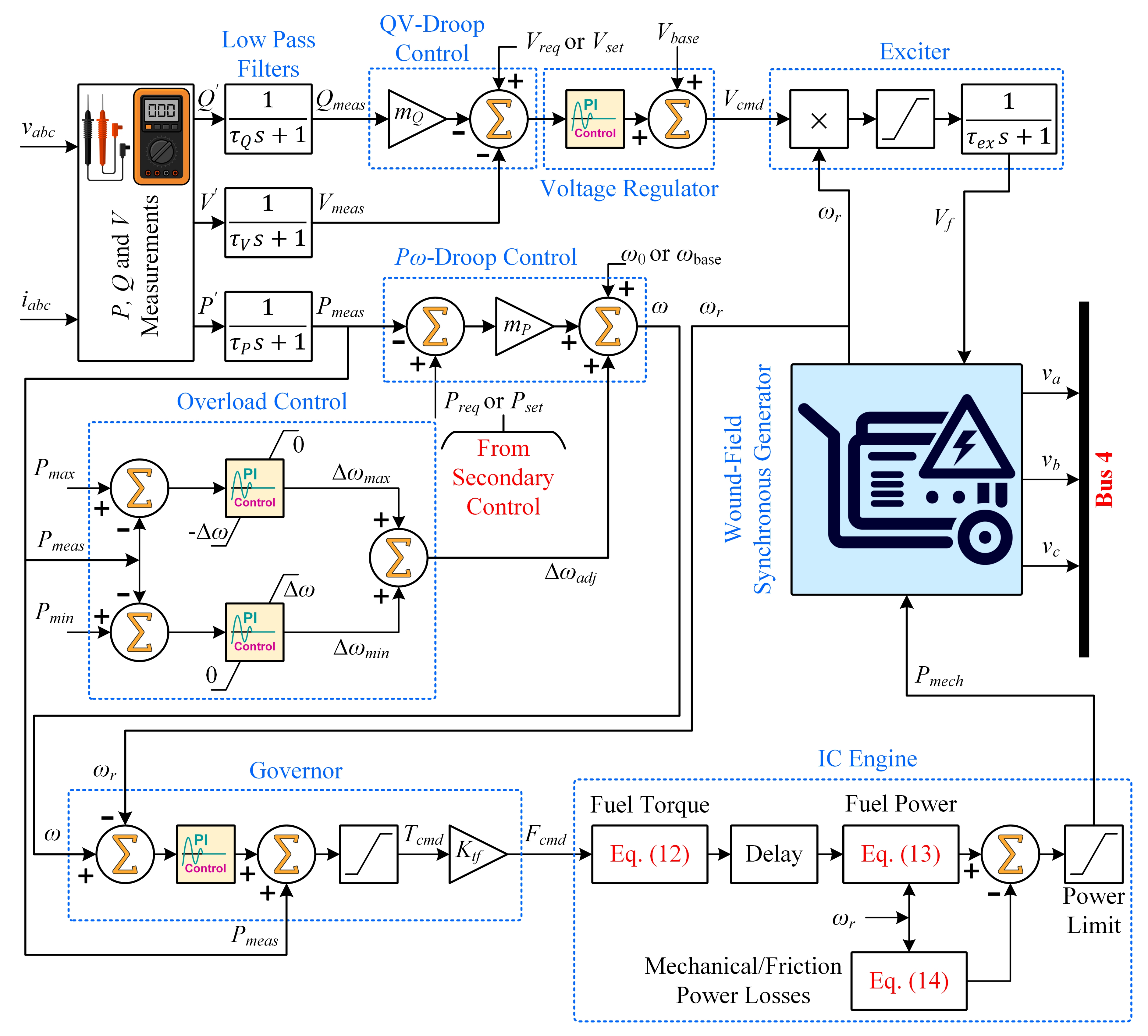
Figure 6a indicates the main grid behavior before and subsequent to disconnection, while Figure 6b–d, respectively, indicates the inverter-based ESS, inverter-based MS and diesel GS behavior under droop/primary control only. During switching to the islanded mode, the MG faced an absence of real power from the main grid. All the DG units adopted the P ω -droop characteristic and, consequently, their frequencies were allowed to drop slightly below the reference value (i.e., f 0 = 60   Hz ). Moreover, to compensate for the real power loss from the main grid, each DG unit immediately began to increase its active power output. This process continued until the total existing real power demand was completely met. At this level, the real power generation of all the three DG units attained a constant value, as illustrated from t = 2 to 4   s . At t = 4   s , there was a load increase event. Due to their negligible inertias, both of the inverter-interfaced DG units (i.e., ESS and MS) further increased their real power generation to fulfill the extra power demand by further dropping their frequencies below the reference value. On the other hand, the rotating-type DG unit (i.e., diesel GS) possessed a high inertia and could not quickly pick up the increased load. Thus, the diesel GS almost retained its previous frequency and power level. It is important to mention that the frequency deviation of each DG unit conformed to the prescribed frequency droop value (i.e., Δ f = 0.5   Hz or 0.833 %).
In the case of several DG units operating in parallel in an MG, the bus voltage regulation to a specific value causes reactive power to circulate between the DG units. This phenomenon enhances the DG units’ rating and reduces the efficiency of the system. To mitigate this problem, a Q V -droop strategy was adopted [52]. As depicted in Figure 6, the circulating reactive powers were easily observable prior to the islanding event at t = 2   s . However, once all the bus voltages were regulated (to V r e q = 120   V line-to-neutral or 208 V phase-to-phase), after the islanding event, the circulating reactive powers between the DG units were reduced to a minimal value. Upon an increase in load at t = 4   s , transient disturbances could be observed in the reactive power-sharing output of each DG unit. It is important to state that the voltage deviation of each bus conformed to the prescribed voltage droop magnitude (i.e., Δ V = 5 ).

5.2. Test 2: Performance Assessment under the Proposed Secondary Scheme with Plug-and-Play Test

In this test, the performance of the proposed control method was analyzed for equal power sharing, frequency regulation and the plug-and-play operation of DG units.
From the start of simulation ( t = 0   s ), the MG was operated in the grid-connected mode, and then it was switched to the islanded mode at t = 2   s . The overall active load demand from t = 0 to 7   s was P L , T o t a l = 12   k W , constituted by the loads connected at the four buses, as follows: P L , B u s 2 = P L , B u s 3 = P L , B u s 4 = 4   k W , while P L , B u s 1 = 0   k W , thus giving an average load of, P L i , a v g = 4   k W per DG unit. Then, the stated overall active demand was augmented to 16 k W by increasing P L , B u s 2 from 4 to 8 k W , from t = 7 to 10   s , thus yielding an average load of P L i , a v g = 5.33   k W per DG unit. From t = 10 to 13   s , P L , B u s 2 was again reduced to 4 k W , thus resulting in an overall active load demand of P L , T o t a l = 12   k W and average load of P L i , a v g = 4   k W per DG unit.
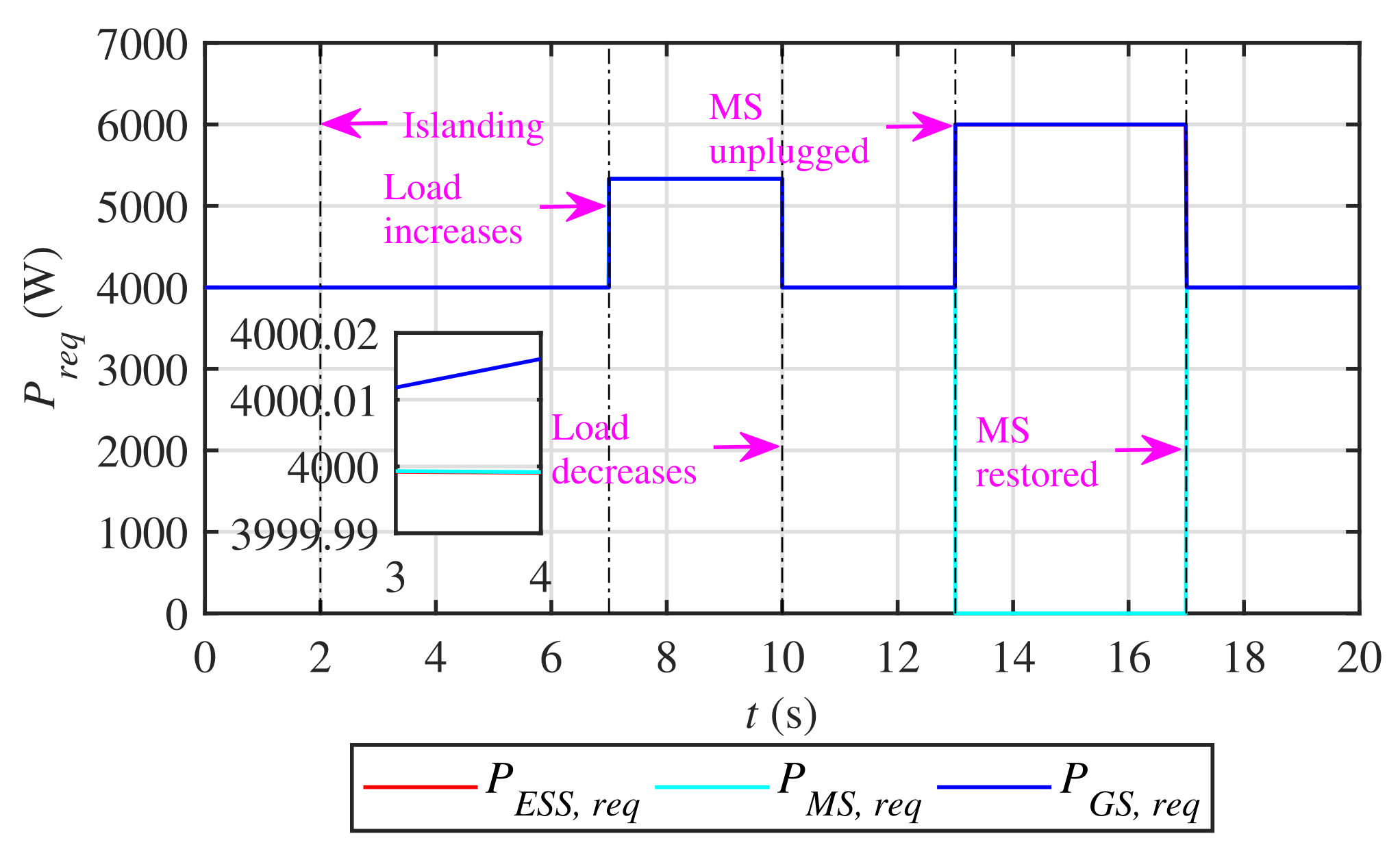
The real powers externally requested from the DG units are illustrated in Figure 7. The proposed control algorithm, expressed in Equation (18), forced these powers to reach an average consensus in a finite time, with c P = 0.001 and α = 0.001 
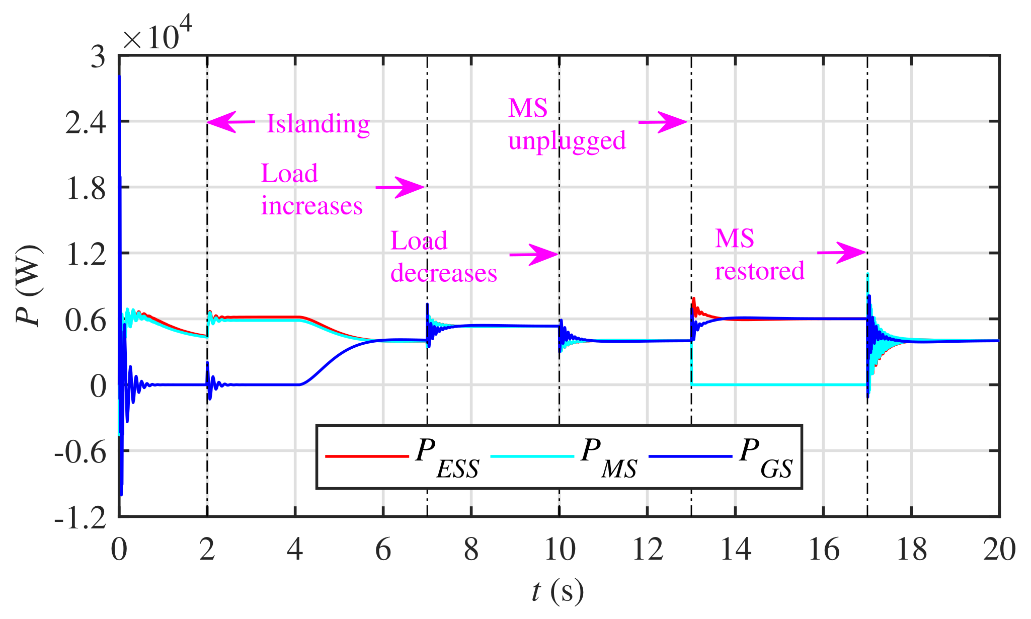
. In response to these agreed-upon values of the requested real powers, each DG unit delivered equal real power despite load perturbations and tracked the system’s average active demand continuously, as shown in Figure 8. Upon islanding at t = 2   s , the real power consensus between DG units was attained within 2 s . After load variation events at t = 7   s and 10   s , the consensus was achieved within 1 s . It can be observed that the individual contribution of each DG unit, in terms of real power, was equal to the system’s average demand, whereas the total real power contribution of the three DG units, as shown in Figure 8, tracked/was equal to the system’s overall active demand.
The plug-and-play attribute for DG units was tested by unplugging the MS at t = 13   s and reconnecting it at t = 17   s . Note that unplugging the MS simultaneously disabled the two-way communication links (i.e., MS⟷ESS and MS⟷GS links), as illustrated in Figure 2. Moreover, unplugging the MS resulted in an increased average demand of P L i , a v g = 6   k W per DG unit. It can be seen in Figure 8 that whether the MS was in service or out of service, average real power consensus was successfully achieved between the DG units in a finite time, and the total load demand was fully satisfied. Consequently, the proposed control strategy supported the plug-and-play operation of the DG units.
Figure 9a–c illustrates the combined behavior of the inverter-based ESS, inverter-based MS and diesel GS, respectively. It is evident that the frequencies of the DG units were quite accurately restored to the reference value (i.e., 60 Hz ) under the load perturbations and the plug-and-play events. The reactive power of each DG unit was minimized and the phase-to-neutral voltage of each DG unit was regulated to its nominal value (i.e., 120 V ). Nonetheless, slight transient disturbances were also observable in the frequencies and voltages under the load perturbations and the plug-and-play events. Under load variations, the bus currents and the active power dispatches varied proportionally.

5.3. Test 3: Performance Assessment under the Proposed Secondary Scheme with Robustness Test against Communication Latency

In this test, the robustness of the proposed control technique to different communication latencies (i.e., 300 m s , 600 m s and 1 s ) was evaluated. As illustrated in Figure 10a–c and Figure 11a–c, the system’s closed-loop response (i.e., real powers and frequencies of the DG units) exhibited more oscillations in the case of communication latency. Moreover, the convergence was retarded under communication latency. It is observed that the oscillations varied in proportion with the communication latency while the convergence varied inversely with the communication latency. Nonetheless, the proposed secondary control technique still managed to fulfill its objectives and effectively tolerated the impact of communication latencies.

5.4. Test 4: Performance Comparison with the Existing Distributed Control Protocol

The performance of the proposed control technique was further compared with the existing distributed control protocol reported in [35,36,37], which can be specified as follows:
P ˙ i , r e q t = P ˙ i , m e a s t = c P j N i P j , m e a s t P i , m e a s t
where c P > 0 .
It can be seen in Figure 12a,b that the existing distributed control protocol reported in [35,36,37] demonstrated slower convergence as well as larger deviations in the power outputs of the DG units than the proposed distributed protocol illustrated in Figure 8 and Figure 9, with similar conditions applied. These deviations were easily observable during the plug-and-play event from t = 13 to 17 s . Likewise, under communication latencies, as shown in Figure 13a,b, the technique reported in [35,36,37] demonstrated much larger oscillations in the power outputs of DG units, especially under larger latencies (i.e., 500 m s ), as compared to the proposed technique illustrated in Figure 10a–c. It is important to mention that under communication latencies, as shown in Figure 13c,d, the method reported in [35,36,37] demonstrated a larger steady-state error in the frequencies of the DG units, especially under larger latencies, where the frequencies were not precisely regulated. On the other hand, the proposed technique was still capable of precisely regulating the frequencies of the DG units, even under a sufficiently large latency of 1 s , as shown in Figure 11a–c.

5.5. Test 5: Sensitivity Analysis of the Proposed Control Scheme

This section demonstrates the sensitivity analysis of the proposed control strategy, as expressed in Equation (18), to gains of c P and α . It is important to mention that in Tests 1–3, as described in Section 5, the proposed control strategy was fine-tuned by choosing c P = 0.001 and α = 0.001 . Now, if c P = 0.001 and α were increased alone, or α = 0.001 and c P were increased alone, the impact on the final results would be invisible to the naked eye. Thus, those results are not included in the article for the sake of brevity. However, it is worth mentioning that if both c P and α were increased simultaneously, the performance of the system would decline; thus, setting c P = 1 and α = 0.5 made the convergence much slower, as depicted in Figure 14a, from t = 4 to 10 s and beyond t = 17 s . Similarly, choosing c P = 5 and α = 0.9 greatly improved the convergence, as depicted in Figure 14b, from t = 4 to 10 s . However, the strategy failed to ensure a proper plug-and-play operation for the MS, as depicted in Figure 14b, where the algorithm did not converge from t = 13 to 17 s . Moreover, it rendered huge spikes upon the restoration of the MS at t = 17 s .

5.6. Test 6: Applicability of the Proposed Control Strategy to a Large System

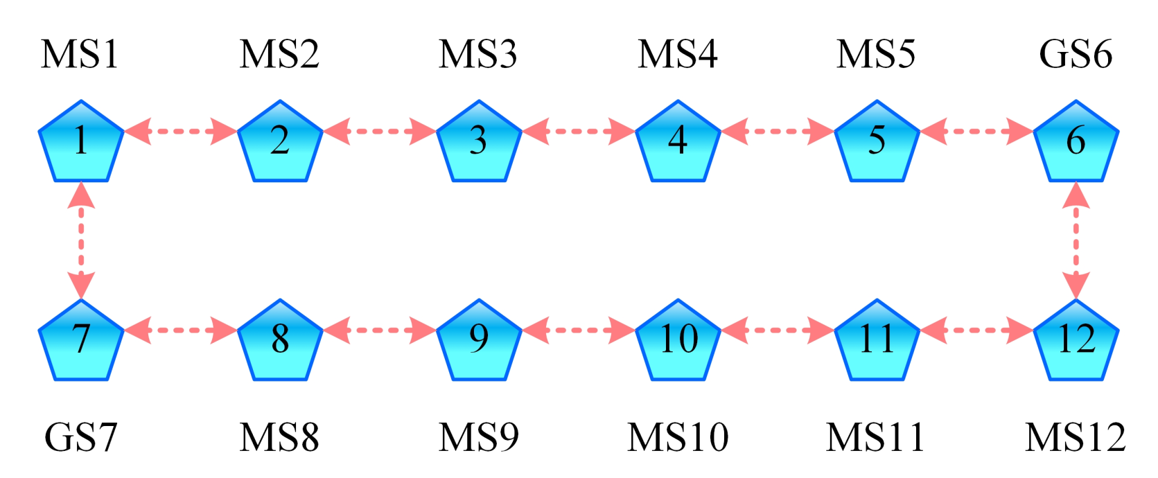
This section demonstrates the applicability of the proposed control strategy, as expressed in Equation (18), to a large microgrid system. The stated system is shown in Figure 15, whereas its communication graph, G , is depicted in Figure 16. The overall active load demand from t = 0 to 7   s was P L , T o t a l = 80   k W , constituted by the loads connected at various buses, thus giving an average load of P L i , a v g = 6.66   k W per DG unit. Then, the stated overall active demand was augmented to P L , T o t a l = 96   k W , from t = 7 to 10   s , thus yielding an average load of P L i , a v g = 8   k W per DG unit. From t = 10 to 13   s , the overall active load demand was again reduced to P L , T o t a l = 80   k W , thus giving an average load of P L i , a v g = 6.66   k W per DG unit. It can be seen in Figure 17a that each DG unit quite accurately fulfilled the average load demand before and after the load perturbations, thus successfully meeting the overall load demand. At the same time, the frequencies of all DG units were regulated to the reference microgrid frequency (i.e., 60 Hz ), as shown in Figure 17b. This implies that the proposed strategy can also be applied to a large microgrid system.

6. Conclusions

In this article, a fully-distributed finite-time consensus-based secondary control protocol is presented for droop-based AC microgrids. The proposed protocol is fully distributed in the sense that each agent of the communication network only requires its own information along with information of its neighbors. It was tested on small as well as large microgrid testbenches with multiple DG units in Matlab/Simulink using time-domain based numerical simulations. This article explicitly takes into account the hierarchical control structure of the DG units; primary control is achieved using the droop control method while secondary control is achieved using the proposed distributed finite-time consensus design. The proposed protocol adjusts the active power outputs of the DG units in such a way that they reach an agreed-upon level in a finite time. At the same time, the frequencies of the DG units are regulated to the reference microgrid frequency in a finite-time. The proposed design is robust to time-varying load perturbations and communication latencies. Moreover, it guarantees a plug-and-play attribute for DG units. The proposed distributed protocol was compared with the existing distributed protocol reported in [35,36,37]; it is observed that the proposed scheme demonstrates superior performance.

Author Contributions

Formal analysis, S.U.; Investigation, S.U.; Supervision, L.K.; Validation, S.U.; Writing—original draft, S.U.; Writing—review & editing, M.J. (Mohsin Jamil), M.J. (Muhammad Jafar), S.M. and S.A. All authors have read and agreed to the published version of the manuscript.

Funding

This research received no external funding.

Institutional Review Board Statement

Not applicable.

Informed Consent Statement

Not applicable.

Data Availability Statement

Not applicable.

Conflicts of Interest

The authors declare no conflict of interest.

Appendix A. System Parameters

Table A1. Microgrid testbench coupling capacitor, coupling inductances and specifications of line impedances.
Line Impedances R ( Ω ) X L ( Ω ) X C ( Ω )
Z 1 0.09340.02552894.30
Z 2 0.002810.0006792894.30
Z E S S 03.770
Z M S 03.770
Z G S 0026.53
Z 12 0.0273520.0066288.60
Z 13 0.01370.0033577.20
Z 24 0.016880.00407336.70
Z 34 0.00260.000642020.10
Table A2. Specifications of microgrid testbench transformers.
TAGRating
( k VA )
Frequency
( Hz )
Primary Side SpecificationsSecondary Side Specifications
V ph ph ( V ) R ( Ω ) X L ( Ω ) V ph ph ( V ) R ( Ω ) X L ( Ω )
T 1 25006041600.047060.18824800.0006270.0025068
T 2 75604800.01690.06762080.00030.0127
T 3 45602080.026880.10752080.0050470.0201
T 4 45602080.026880.10752080.0050470.0201
T 5 45602080.026880.10752080.0050470.0201
Table A3. Specifications of the inverter-based microsource and energy storage system.
Microsource SpecificationsEnergy Storage System Specifications
QuantityValueQuantityValue
S b a s e 15 k VA S b a s e 15 k VA
V b a s e 208 V V b a s e 208 V
V D C 750 V V D C 750 V
f 0 60 Hz f 0 60 Hz
Δ f 0.50 Hz Δ f 0.50 Hz
ω 0 377 rad / s ω 0 377 rad / s
Δ ω π rad / s Δ ω π rad / s
P m a x 15   k W = 1 pu P m a x 15   k W = 1 pu
P m i n 0 k W P m i n 2.50   k W = 0.1667 pu
V r e q 208   V = 1 pu V r e q 208   V = 1 pu
K P p r o 3 K P p r o 3
K P i n t 30 K P i n t 30
K V p r o 0.01 K V p r o 0.01
K V i n t 5 K V i n t 5
m P π m P 2.6928
m Q 0.05 m Q 0.05
τ V , τ P , τ Q 0.01 s τ V , τ P , τ Q 0.01 s
Table A4. Diesel genset specifications.
Genset Specifications
(Synchronous Generator, Speed Governor, IC Engine and Field Exciter)
QuantityValueQuantityValue
S b a s e 12.50 k VA X q 0.53301
V b a s e 208 V X q 0.051
f 0 60 Hz X l 0.037
Δ f 0.50 Hz T d 0.35523
ω 0 377 rad / s T d 0.00015
Δ ω π rad / s T q 0.0067
P m a x 12.50   k W = 1 pu R s 0.0217 pu
P m i n 0 k W H ( s ) 0.1901
V r e q 208   V = 1 pu p2
K P p r o 3 K G p 10
K P i n t 30 K G i 20
K V p r o 1000 K t f 0.625
K V i n t 10 K e v 11.8238
m P π K f v 3600
m Q 0.05 η t h r 0.47
τ V , τ P , τ Q 0.01 s τ d 0.022 s
X d 1.204 K m 0.36
X d 0.125 τ e x 0.001 s
X d 0.056......

References

  1. Lasseter, B. Microgrids [distributed power generation]. In Proceedings of the 2001 IEEE Power Engineering Society Winter Meeting (Conference Proceedings (Cat. No.01CH37194)), Columbus, OH, USA, 28 January–1 February 2001; pp. 146–149. [Google Scholar]
  2. Lasseter, R.H. Microgrids. In Proceedings of the 2002 IEEE Power Engineering Society Winter Meeting (Conference Proceedings (Cat. No.02CH37309)), New York, NY, USA, 27–31 January 2002; pp. 305–308. [Google Scholar]
  3. Lasseter, R.H. Extended CERTS microgrid. In Proceedings of the 2008 IEEE Power and Energy Society General Meeting-Conversion and Delivery of Electrical Energy in the 21st Century (Conference Proceedings (Cat. No.02CH37309)), Pittsburgh, PA, USA, 20–24 July 2008; pp. 1–5. [Google Scholar]
  4. Lasseter, R.H.; Piagi, P. Microgrid: A conceptual solution. In Proceedings of the 2004 IEEE 35th Annual Power Electronics Specialists Conference (IEEE Cat. No. 04CH37551), Aachen, Germany, 20–25 June 2004; pp. 4285–4290. [Google Scholar]
  5. Baghaee, H.R. Real-time verification of new controller to improve small/large-signal stability and fault ride-through capability of multi-DER microgrids. IET Gener. Transm. Distrib. 2016, 10, 3068–3084. [Google Scholar] [CrossRef]
  6. Nikkhajoei, H.; Lasseter, R.H. Distributed generation interface to the CERTS microgrid. IEEE Trans. Power Deliv. 2009, 24, 1598–1608. [Google Scholar] [CrossRef]
  7. Katiraei, F. Micro-Grid autonomous operation during and subsequent to islanding process. IEEE Trans. Power Deliv. 2005, 20, 248–257. [Google Scholar] [CrossRef]
  8. Farrokhabadi, M.; Cañizares, C.A.; Simpson-Porco, J.W.; Nasr, E.; Fan, L. Microgrid stability definitions, analysis, and examples. IEEE Trans. Power Syst. 2019, 35, 13–29. [Google Scholar] [CrossRef]
  9. IEEE 2030.7-2017—IEEE Standard for the Specification of Microgrid Controllers. Available online: https://ieeexplore.ieee.org/document/8340204 (accessed on 1 April 2021).
  10. D’silva, S.; Shadmand, M.B.; Abu-Rub, H. Microgrid Control Strategies for Seamless Transition Between Grid-Connected and Islanded Modes. In Proceedings of the 2020 IEEE Texas Power and Energy Conference (TPEC), College Station, TX, USA, 6–7 February 2020; pp. 1–6. [Google Scholar]
  11. Pérez-Ibacache, R.; Silva, C.A.; Yazdani, A. Linear state-feedback primary control for enhanced dynamic response of AC microgrids. IEEE Trans. Smart Grid 2018, 10, 3149–3161. [Google Scholar] [CrossRef]
  12. Baghaee, H.R.; Mirsalim, M.; Gharehpetian, G.B.; Talebi, H.A. Unbalanced harmonic power sharing and voltage compensation of microgrids using radial basis function neural network-based harmonic power-flow calculations for distributed and decentralised control structures. IET Gener. Transm. Distrib. 2018, 12, 1518–1530. [Google Scholar] [CrossRef]
  13. Lopes, J.A.P.; Moreira, C.L.; Madureira, A.L.G. Defining control strategies for microgrids islanded operation. IEEE Trans. Power Syst. 2006, 21, 916–924. [Google Scholar] [CrossRef] [Green Version]
  14. Cucuzzella, M.; Incremona, G.P.; Ferrara, A. Decentralized sliding mode control of islanded AC microgrids with arbitrary topology. IEEE Trans. Ind. Electron. 2017, 64, 6706–6713. [Google Scholar] [CrossRef] [Green Version]
  15. Savaghebi, M.; Jalilian, A.; Vasquez, J.C. Secondary control scheme for voltage unbalance compensation in an islanded droop-controlled microgrid. IEEE Trans. Smart Grid 2012, 3, 797–807. [Google Scholar] [CrossRef] [Green Version]
  16. Bidram, A.; Davoudi, A.; Lewis, F.L.; Ge, S.S. Distributed adaptive voltage control of inverter-based microgrids. IEEE Trans. Energy Convers. 2014, 13, 862–872. [Google Scholar] [CrossRef]
  17. Guerrero, J.M.; Chandorkar, M.; Lee, T.-L.; Loh, P.C. Advanced control architectures for intelligent microgrids—Part I: Decentralized and hierarchical control. IEEE Trans. Ind. Electron. 2013, 60, 1254–1262. [Google Scholar] [CrossRef] [Green Version]
  18. Hu, J.; Bhowmick, P. A consensus-based robust secondary voltage and frequency control scheme for islanded microgrids. Int. J. Electr. Power Energy Syst. 2020, 116, 105575. [Google Scholar] [CrossRef]
  19. Bidram, A.; Davoudi, A. Hierarchical structure of microgrids control system. IEEE Trans. Smart Grid 2012, 18, 1963–1976. [Google Scholar] [CrossRef]
  20. Vasilakis, A.; Zafeiratou, I.; Lagos, D.; Hatziargyriou, N. The Evolution of Research in Microgrids Control. IEEE Open Access J. Power Energy 2020, 7, 331–343. [Google Scholar] [CrossRef]
  21. Shahab, M.A.; Mozafari, B.; Soleymani, S.; Dehkordi, N.M.; Shourkaei, H.M.; Guerrero, J.M. Distributed consensus-based fault tolerant control of islanded microgrids. IEEE Trans. Smart Grid 2019, 11, 37–47. [Google Scholar] [CrossRef]
  22. Dehkordi, N.M.; Sadati, N.; Hamzeh, M. Distributed robust finite-time secondary voltage and frequency control of islanded microgrids. IEEE Trans. Power Syst. 2016, 32, 3648–3659. [Google Scholar] [CrossRef]
  23. Olfati-Saber, R.; Murray, R.M. Consensus problems in networks of agents with switching topology and time-delays. IEEE Trans. Autom. Control 2004, 49, 1520–1533. [Google Scholar] [CrossRef] [Green Version]
  24. Ren, W.; Beard, R.W. Consensus seeking in multiagent systems under dynamically changing interaction topologies. IEEE Trans. Autom. Control 2005, 50, 655–661. [Google Scholar] [CrossRef]
  25. Ren, W.; Beard, R.W.; Atkins, E.M. Information consensus in multivehicle cooperative control. IEEE Control Syst. Mag. 2007, 27, 71–82. [Google Scholar]
  26. Lai, J.; Zhou, H.; Lu, X.; Yu, X.; Hu, W. Droop-based distributed cooperative control for microgrids with time-varying delays. IEEE Trans. Smart Grid 2016, 7, 1775–1789. [Google Scholar] [CrossRef]
  27. Afshari, A.; Karrari, M.; Baghaee, H.R.; Gharehpetian, G.B.; Karrari, S. Cooperative fault-tolerant control of microgrids under switching communication topology. IEEE Trans. Smart Grid 2019, 11, 1866–1879. [Google Scholar] [CrossRef]
  28. Liu, S.; Wang, X.; Liu, P.X. Impact of communication delays on secondary frequency control in an islanded microgrid. IEEE Trans. Ind. Electron. 2014, 62, 2021–2031. [Google Scholar] [CrossRef]
  29. Bidram, A.; Davoudi, A.; Lewis, F.L.; Guerrero, J.M. Distributed cooperative secondary control of microgrids using feedback linearization. IEEE Trans. Power Syst. 2013, 28, 3462–3470. [Google Scholar] [CrossRef] [Green Version]
  30. Bidram, A.; Davoudi, A.; Lewis, F.L.; Qu, Z. Secondary control of microgrids based on distributed cooperative control of multi-agent systems. IET Gener. Transm. Distrib. 2013, 7, 822–831. [Google Scholar] [CrossRef] [Green Version]
  31. Dehkordi, N.M.; Sadati, N.; Hamzeh, M. Fully distributed cooperative secondary frequency and voltage control of islanded microgrids. IEEE Trans. Energy Convers. 2016, 32, 675–685. [Google Scholar] [CrossRef]
  32. Ge, P.; Zhu, Y.; Green, T.; Teng, F. Resilient Secondary Voltage Control of Islanded Microgrids: An ESKBF-Based Distributed Fast Terminal Sliding Mode Control Approach. IEEE Trans. Power Syst. 2020, 36, 1059–1070. [Google Scholar] [CrossRef]
  33. Chen, M.; Xiao, X. Secondary voltage control in islanded microgrids using event-triggered control. IET Gener. Transm. Distrib. 2018, 12, 1872–1878. [Google Scholar]
  34. Arefifar, S.A.; Ordonez, M.; Mohamed, Y.A.-R.I. Voltage and current controllability in multi-microgrid smart distribution systems. IEEE Trans. Smart Grid 2016, 9, 817–826. [Google Scholar]
  35. Nguyen, D.H.; Khazaei, J. Multiagent time-delayed fast consensus design for distributed battery energy storage systems. IEEE Trans. Sustain. Energy 2017, 9, 1397–1406. [Google Scholar] [CrossRef]
  36. Khazaei, J.; Nguyen, D.H. Multi-agent consensus design for heterogeneous energy storage devices with droop control in smart grids. IEEE Trans. Smart Grid 2017, 10, 1395–1404. [Google Scholar] [CrossRef]
  37. Ullah, S.; Khan, L.; Badar, R.; Ullah, A.; Karam, F.W.; Khan, Z.A.; Rehman, A.U. Consensus based SoC trajectory tracking control design for economic-dispatched distributed battery energy storage system. PLoS ONE 2020, 15, e0232638. [Google Scholar] [CrossRef]
  38. Bidram, A.; Nasirian, V.; Davoudi, A.; Lewis, F.L. Cooperative Synchronization in Distributed Microgrid Control; Springer International Publishing AG: Cham, Switzerland, 2017. [Google Scholar]
  39. Chen, F.; Ren, W. Distributed Average Tracking in Multi-Agent Systems; Springer Nature Switzerland AG: Cham, Switzerland, 2020. [Google Scholar]
  40. Ullah, S.; Khan, L.; Sami, I.; Ullah, N. Consensus-based delay-tolerant distributed secondary control strategy for droop controlled AC microgrids. IEEE Access 2021, 9, 6033–6049. [Google Scholar] [CrossRef]
  41. Erickson, M.J.; Lasseter, R.H. Integration of battery energy storage element in a CERTS microgrid. In Proceedings of the 2010 IEEE Energy Conversion Congress and Exposition, Atlanta, GA, USA, 12–16 September 2010; pp. 2570–2577. [Google Scholar]
  42. Lasseter, R.H.; Piagi, P. Control and Design of Microgrid Components; Power Systems Engineering Research Center (PSERC), University of Wisconsin-Madison: Madison, WI, USA, 2006. Available online: https://certs.lbl.gov/sites/all/files/ctrl-design-microgrid-components.pdf (accessed on 20 October 2020).
  43. Du, W.; Lasseter, R.H. Overload mitigation control of droop-controlled grid-forming sources in a microgrid. In Proceedings of the 2017 IEEE Power & Energy Society General Meeting, Chicago, IL, USA, 16–20 July 2017; pp. 1–5. [Google Scholar]
  44. Hosseinzadeh, M.; Schenato, L.; Garone, E. A Distributed Optimal Power Management System for Microgrids with Plug & Play Capabilities. Adv. Control Appl. Eng. Ind. Syst. 2021, 3, e65. [Google Scholar]
  45. Wang, R.; Tang, H.; Xu, Y. Distributed cooperative optimal control of energy storage systems in a microgrid. In Proceedings of the 2016 IEEE Power and Energy Society General Meeting (PESGM), Boston, MA, USA, 17–21 July 2016; pp. 1–5. [Google Scholar]
  46. Liu, X.; Lam, J.; Yu, W.; Chen, G. Finite-time consensus of multiagent systems with a switching protocol. IEEE Trans. Neural Netw. Learn. Syst. 2015, 27, 853–862. [Google Scholar] [CrossRef] [PubMed]
  47. Hosseinzadeh, M.; Yazdanpanah, M.J. Performance enhanced model reference adaptive control through switching non-quadratic Lyapunov functions. Syst. Control Lett. 2015, 76, 47–55. [Google Scholar] [CrossRef]
  48. Zhang, Q.-Q.; Wai, R.-J. Robust Power Sharing and Voltage Stabilization Control Structure via Sliding-Mode Technique in Islanded Micro-Grid. Energies 2021, 14, 883. [Google Scholar] [CrossRef]
  49. Hardy, G.H.; Littlewood, J.E.; Pólya, G. Inequalities; Cambridge University Press: Cambridge, UK, 1988. [Google Scholar]
  50. Zhang, H.; Lewis, F.L.; Qu, Z. Lyapunov, adaptive, and optimal design techniques for cooperative systems on directed communication graphs. IEEE Trans. Ind. Electron. 2012, 59, 3026–3041. [Google Scholar] [CrossRef]
  51. Forti, M.; Grazzini, M.; Nistri, P.; Pancioni, L. Generalized Lyapunov approach for convergence of neural networks with discontinuous or non-Lipschitz activations. Physica D 2006, 214, 88–99. [Google Scholar] [CrossRef]
  52. Krishnamurthy, S.; Jahns, T.M.; Lasseter, R.H. The operation of diesel gensets in a CERTS microgrid. In Proceedings of the 2008 IEEE Power and Energy Society General Meeting-Conversion and Delivery of Electrical Energy in the 21st Century, Pittsburgh, PA, USA, 20–24 July 2008; pp. 1–8. [Google Scholar]
Figure 1. Microgrid testbench.
Energies 14 02936 g001
Figure 2. Communication graph.
Energies 14 02936 g002
Figure 3. Droop/primary control and overload control for inverter-based microsource.
Energies 14 02936 g003
Figure 4. Droop/primary control and overload control for GS.
Energies 14 02936 g004
Figure 5. Overall closed-loop implementation of the proposed control strategy.
Energies 14 02936 g005
Figure 6. The main grid and DG units performance under droop/primary control alone.
Energies 14 02936 g006
Figure 7. Real powers externally requested from DG units.
Energies 14 02936 g007
Figure 8. Power sharing output of each DG unit.
Energies 14 02936 g008
Figure 9. Inverter-based external energy storage system.
Energies 14 02936 g009
Figure 10. Power sharing outputs of DG units under different communication latencies: (a) 300 ms (b) 600 ms, and (c) 1 s.
Energies 14 02936 g010
Figure 11. Frequency restoration test for DG units with different communication latencies: (a) 300 (b 600 ms and (c) 1s.
Energies 14 02936 g011aEnergies 14 02936 g011b
Figure 12. Power sharing outputs and frequency reculation of DG units during plug-and-play operation using the existing protocolm as reported in [35,36,37].
Energies 14 02936 g012
Figure 13. Power sharing outputs and frequency reculation of DG units undrer different communitation latencies using the existing protocol, as reported in [35,36,37].
Energies 14 02936 g013
Figure 14. Power sharing outputs of DG units under different gain parameters.
Energies 14 02936 g014
Figure 15. Large microgrid.
Energies 14 02936 g015
Figure 16. Communication graph for the large microgrid.
Energies 14 02936 g016
Figure 17. Power sharing outputs and frequencies of DG units for a large microgrid system.
Energies 14 02936 g017
Publisher’s Note: MDPI stays neutral with regard to jurisdictional claims in published maps and institutional affiliations.

