Article

Lithium-Ion Capacitor Lifetime Extension through an Optimal Thermal Management System for Smart Grid Applications

1
Research Group MOBI—Mobility, Logistics, Automotive Technology Research Centre, Vrije Universiteit Brussel, Pleinlaan 2, 1050 Brussels, Belgium
2
Flanders Make, 3001 Heverlee, Belgium
*
Author to whom correspondence should be addressed.
Energies 2021, 14(10), 2907; https://doi.org/10.3390/en14102907
Submission received: 19 April 2021 / Revised: 12 May 2021 / Accepted: 14 May 2021 / Published: 18 May 2021

Abstract

:
A lithium-ion capacitor (LiC) is one of the most promising technologies for grid applications, which combines the energy storage mechanism of an electric double-layer capacitor (EDLC) and a lithium-ion battery (LiB). This article presents an optimal thermal management system (TMS) to extend the end of life (EoL) of LiC technology considering different active and passive cooling methods. The impact of different operating conditions and stress factors such as high temperature on the LiC capacity degradation is investigated. Later, optimal passive TMS employing a heat pipe cooling system (HPCS) is developed to control the LiC cell temperature. Finally, the effect of the proposed TMS on the lifetime extension of the LiC is explained. Moreover, this trend is compared to the active cooling system using liquid-cooled TMS (LCTMS). The results demonstrate that the LiC cell temperature can be controlled by employing a proper TMS during the cycle aging test under 150 A current rate. The cell’s top surface temperature is reduced by 11.7% using the HPCS. Moreover, by controlling the temperature of the cell at around 32.5 and 48.8 °C, the lifetime of the LiC would be extended by 51.7% and 16.5%, respectively, compared to the cycling of the LiC under natural convection (NC). In addition, the capacity degradation for the NC, HPCS, and LCTMS case studies are 90.4%, 92.5%, and 94.2%, respectively.

1. Introduction

Recently, the growth of electric vehicles (EVs) and hybrid electric vehicles (HEVs) has been significantly enhanced due to the reduction of emissions and the beneficial impacts on global warming [1]. Electrical energy storage systems that are known as batteries are the most crucial part of EVs and HEVs [2]. Among all types of batteries, lithium-ion batteries (LiB) are popular due to their high energy density and long cyclic life [3]. However, LiBs produce excessive heat during charging/discharging, and their capacities are highly temperature-dependent [4]. Therefore, LiBs suffer from lifetime degradation when used as a simultaneously efficient energy source in high temperatures [5].
On the other hand, electric double-layer capacitors (EDLC) are high power energy storage systems with long lifetime, but they suffer from low energy density [6]. Therefore, lithium-ion capacitors (LiC) have been revealed and commercialized by several manufacturers that combine favorable properties of EDLCs and LiBs [7]. Generally, the LiC has longer cycle life and higher power density compared to LiBs [8]. The LiC is an ideal choice for many applications, comprising HEVs and EVs for peak power shaving [9], regenerative braking [10], and grid applications [11].
The performance of the LiC cell components significantly depends on the operational temperature. As the generated heat inside LiCs would change the internal temperature, it could lead to the change of reaction kinetics and facilitate the degradation phenomena. Therefore, implementation of an efficient thermal management system (TMS) would have vital role to inhibit the material degradation processes and can consequently increase the lifetime of the cell. The LiC consists of an EDLC type cathode material, a pre-lithiated LiB anode material, and an organic electrolyte containing lithium-ion [12]. To understand the impact of the operational temperature on the LiC cell’s performance, the effect of temperature on the LiC cell components is investigated in this work.
The investigated LiC cell has LTO as anode material. LTO is commonly used as the negative electrode, which features good capacity [6]. LTO, as the LiB anode, has high interfacial side reactivity with the electrolyte, which can lead to gas generation and poor cycling stability [13]. Huang et al. have investigated the temperature dependence of LTO degradation in LiBs. They have shown that the cell’s capacity retention would decrease at elevated temperatures; LTO could deliver up to 87.1% capacity retention in low C-rates (1 C, 60 °C, 500 Cycles). However, with raising the C-rate, the capacity retention had drastically dropped to 20.9% (5 C, 60 °C, 500 Cycles) [14]. Considering that high C-rates are in the interest of LiC applications, it is expected that controlling the temperature and keeping that in lower values could cause the LiC lifetime’s amelioration. Within another investigation, Yang et al. have evaluated the rate capability of LTO in a LiB cell at different temperatures from 0.5 C to 20 C and depicted 35 °C as the most efficient temperature for different C-rate values [15].
The electrolyte is also a vulnerable cell component against heat. Many common LiC electrolytes are based on carbonate solvents. Handel et al. have investigated the effect of high temperature on degradation of pure LiPF6/carbonate-based electrolyte stored for 28 days at 60 °C and demonstrated that the electrolyte’s total impurity content had been increased by about 2.5 times in comparison with the fresh electrolyte [16]. Smart et al. have also reported degradation of LiPF6/carbonate-based electrolytes at elevated temperatures [17]. To understand the aging factors, El Ghossein et al. have performed calendar accelerated aging tests on LiC cells cycled at 70 °C followed by a post-mortem study and concluded that pore-blocking at the positive electrode could decrease the capacitance values of the LiC cell and main aging mechanism of the positive electrode is reported as the pore blocking of the activated carbon due to parasitic reactions between the functional groups present on its surface and the components of the electrolyte [18]. This research has also demonstrated the degradation of the positive current collector’s electrolyte and decomposition at high voltages.
According to what was mentioned, it could be concluded that internal heat, which would raise the operating temperature, could be considered as an affecting aging factor in LiC cells. Therefore, the application of LiCs requires a proper TMS to extend the lifetime of the cell. Generally, there are two types of cooling systems comprising active and passive cooling methods. Active cooling systems are categorized into air cooling [19] and liquid cooling systems [20]. The air cooling method is simple with low cost, but its thermal performance is low [21]. Liquid cooling method is the most promising active cooling system with high cooling efficiency, but the system’s maintenance costs and possible leakage are among their disadvantages [22]. On the other hand, passive cooling systems are categorized into phase change materials (PCM) [23] and heat pipes [24]. Employing PCMs as an efficient TMS has some problems, such as low thermal conductivity and thermal stability [25,26]. Moreover, the cost of PCMs impacts their limited usage [27,28]. Heat pipes as passive superconductors benefit from flexible geometry, low cost, and high efficiency [29]. It is necessary to employ heat pipes with other cooling methods to increase their effectiveness [30,31].
Since LiCs are energy storage systems with long cycle life, the lifetime testing of the LiCs under real-life conditions is not practical. Therefore, accelerated aging tests are one of the possible solutions to investigate the lifetime of LiCs [32]. Hence, the best way to analyze the degradation of the LiCs is the empirical approach in which real-life tests would be performed at various operating conditions. Then, the capacity fade of the cell is estimated by extrapolation employing curve fitting techniques. The fitted capacity degradation trend can be a logarithmic, exponential, or polynomial equation, which is an acceptable fit for the current state, but the prediction of the future state might be unacceptable for some cases [33]. The impact of active and passive TMSs on the lifetime of the LiC cell is studied in this work, and evaluation of the degradation behavior in three use cases is analyzed using the curve fitting technique to accurately predict the capacity degradation trend for the current state and the future state of all three use cases.
In this research article, the proposed TMS is a heat pipe cooling system (HPCS) designed to control the temperature evolution of the LiC. To the authors’ best knowledge, this is the first time that HPCS is cooling a LiC cell. Therefore, the paper’s novelty lies in the proposed TMS to keep the LiC temperature at the desired range. Besides, in the current study, the lifetime of the LiC has been investigated using the HPCS.
Moreover, a compact and optimized liquid-cooled TMS (LCTMS) from our previous work is utilized to investigate the impact of an active cooling system on the capacity degradation of the LiC. The lifetime testing of the cell is performed using a 150 A charge/discharge current rate without pause. Hence, three scenarios are studied: cycling the cell under natural convection (NC), cycling the cell when the cell is being cooled by HPCS, and cycling the cell when the LCTMS is employed. The influence of these three scenarios on the end of life (EoL) degradation of the LiC is studied and compared to understand how the lifetime of the LiC can be extended using an optimal TMS.

2. Experimental Methodology

A passive TMS is employed for this study to absorb the generated heat of the LiC cell during the continuous 150 A charge/discharge current rate, which can be considered as a high-duty driving cycle. The LiC cell is a commercial 2300 F prismatic cell manufactured by JSR Company, promising energy storage for grid applications. It should be mentioned that F is the Faraday constant, which is the magnitude of electric charge per mole of electrons.

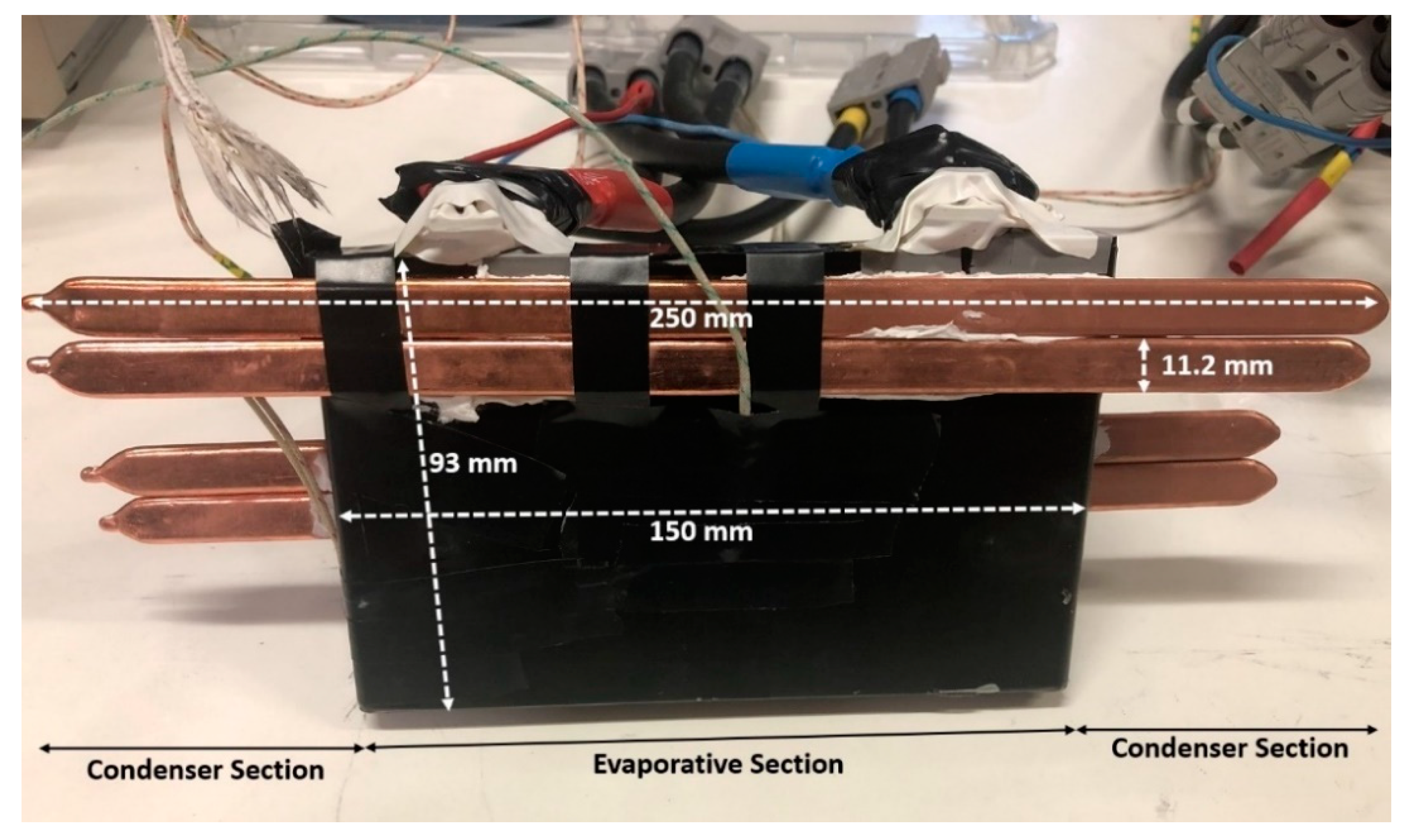
2.1. Lithium-Ion Capacitor (LiC) Technology

The LiC technology is a hybrid energy storage system consisting of doped graphite similar to LiBs anode material, activated carbon (AC) like EDLCs cathode material, and an organic electrolyte [12]. Based on this hybridization, the benefits of EDLCs such as long life and high specific power, and advantages of LiBs such as high specific Energy make LiCs a promising technology for grid applications. Anode and cathode materials, pre-lithiation of the anode, electrode configurations, and electrolyte types are among the main factors that affect the performance of LiCs [34]. Thermo-physical properties of the investigated LiC cell are listed in Table 1.

2.2. Heat Pipe Cooling System (HPCS)

Figure 1 exhibits the HPCS for the prismatic 2300 F LiC cell and the related dimensions. In this cooling system, four flat heat pipes manufactured by Digi-Key Electronics are used, in which two heat pipes are utilized on each side of the LiC cell (four heat pipes in total) because the most heat generation zones are close to the cell tabs. The characteristics of the utilized heat pipe are listed in Table 2. The proposed TMS using HPCS absorbs the generated heat by the LiC and transfers it to the ambient. Moreover, since the heat pipes are in direct contact with the cell, a thin layer of thermal interface material (TIM) is applied to fill the gaps between the cell and the heat pipes. Using the TIM decreases the thermal contact resistance and avoids the production of substantial thermal barriers. The proposed TMS is developed to cool down the LiC cell during an intense 150 A charge/discharge cycling regime.
When the cell is cycled, the heat is generated inside the LiC cell. This generated heat is transferred from the evaporator to the condenser section of the heat pipes through conduction. Then, the heat is removed from the condenser section to the ambient through convection. To investigate the performance of the proposed TMS, two scenarios have been conducted. The first scenario deals with analyzing the LiC cell’s thermal behavior under NC without using any cooling system. The second scenario investigates the thermal behavior of the LiC cell considering the proposed TMS using HPCS. After evaluating the positive impacts of the second scenario, the effect of the proposed TMS on the cell’s lifetime is studied.

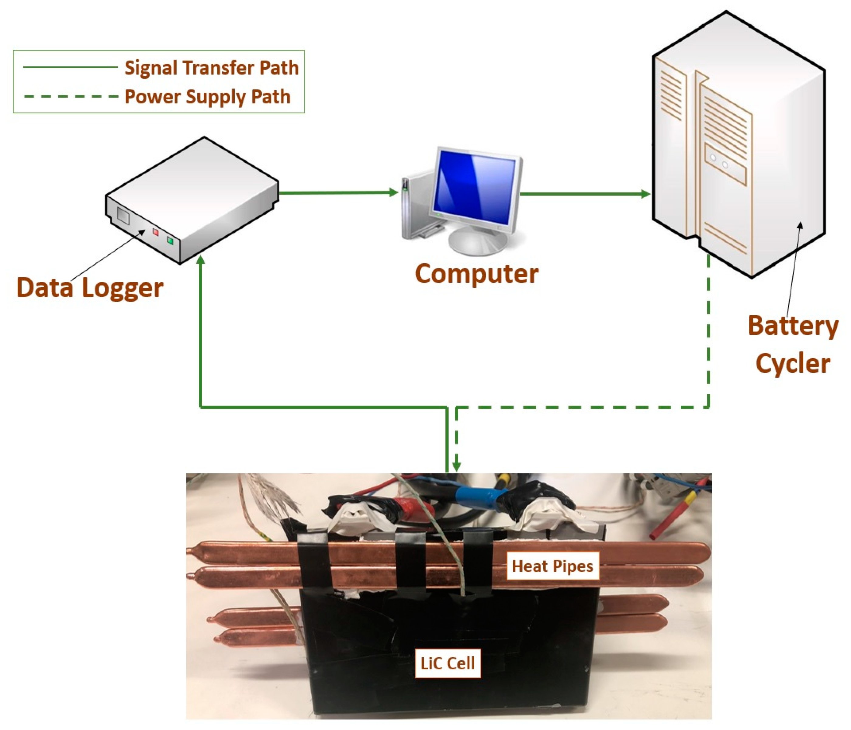
2.3. Experimental Test Bench

The prismatic LiC cell is embedded with HPCS to develop a passive cooling system with high-temperature uniformity. The main investigation on the HPCS is carried out as follows. Four flat heat pipes were used, in which there are an evaporator section and two condenser sections. It has been proven that heat pipes’ thermal performance would be enhanced by increasing the number of condenser sections [35]. The experimental test bench was developed to study the cooling effect of the TMS using HPCS to extend the LiC cell’s lifetime when being charged/discharged at 150 A current rate.
The schematic of the experimental test bench is exhibited in Figure 2. The experimental test bench comprises a prismatic LiC cell, four flat heat pipes, the PEC SBT05250L tester, a data logger, a thermal camera, three k-type thermocouples, and a computer to monitor and save the data from the data logger. The thermocouples are calibrated with an error of ±0.2 °C. The PEC SBT05250L tester is cycling the cell to gather the needed data thanks to the connected computer. Employing this experimental test bench allows monitoring the current, voltage, and temperature of the cell. The thermocouples were placed in three different parts of the cell to sense the temperature. Moreover, the cell is put inside a room with a controlled constant temperature of 23 °C. The cycling of the LiC cell is conducted at a high current rate of 150 A.
Moreover, based on the Schultz and Cole method, the uncertainty of the experimental test can be expressed as follows [36]:
U R = [ i = 1 n ( R V I U V I ) 2 ] 1 / 2
where U V I denotes the error of every single factor and U R stands for total errors. The maximum uncertainty is expressed in percentage, which was calculated as 2.01%.

2.4. Test Definition and Setup

The characterization is the first essential step to identify the LiC cell parameters. Therefore, some tests should be carried out to characterize the cell under some predefined conditions. The electro-thermal tests are conducted employing the battery cycler and the climate chamber. The experimental process consists of a pre-conditioning test, capacity test, open-circuit voltage (OCV) test, hybrid pulse power characterization (HPPC) test, and validation test [7].
Figure 3 presents one period of the load profile used for the cycle aging test of the LiC under 150 A current rate.

2.5. Experimental Results

The experimental results of the tested scenarios are explained in this section. The first scenario deals with the temperature profile of the cell under NC at an initial temperature of 23 °C. Therefore, in this scenario, the cell’s temperature contour is achieved under NC (buoyancy-driven convection) without employing any TMS. This method is regularly used for cooling systems of electronic devices. Moreover, utilizing this method would mean no additional tools that save the system’s energy, volume, and cost by eliminating the maintenance cost. Nonetheless, this method’s thermal performance is relatively low and needs to be further improved. To investigate the performance of this scenario, the LiC cell is cycled under NC with 150 A current rate at room temperature of 23 °C.
The temperature variation of the LiC cell in the NC method is illustrated in Figure 4. One thermocouple is placed in the top center of the cell (T1), while two other thermocouples are placed in the edge and center middle of the LiC cell (T2 and T3). As is evident, the temperature evolution of the T1 thermocouple is higher than the T2 and T3 thermocouples, which shows that the temperature is higher near the top and center of the cell compared to the other lower parts of the cell. According to Figure 4, the maximum LiC cell temperature through NC in 1400 s reaches 55.3, 52.3, and 51.7 °C for T1, T2, and T3 thermocouples, respectively. This high temperature goes beyond the recommended temperature announced by the manufacturer. Therefore, there is a crucial need to propose a proper TMS to extend the cell’s lifetime.
In the second scenario, the cell is placed between four heat pipes to investigate the thermal performance of the HPCS. The initial temperature is 23 °C, the same as the NC. Figure 5 demonstrates the temperature distribution of the cell during the 150 A charge/discharge cycling regime. In practice, the HPCS has a relatively good impact on the temperature contour of the cell. The T1 thermocouple reaches 48.8 °C, while T2 and T3 thermocouples monitor 47.5 and 48.4 °C, respectively. Moreover, the temperature evolution trend for all the thermocouples is almost the same.
Table 3 illustrates the comparison study of the thermocouples’ cell temperatures for both the scenarios with TMS and without TMS under NC. As can be seen, the proposed HPCS can cool down the temperature between 7.5% and 11.7%, depending on the thermocouples’ position. Moreover, the temperature uniformity of the cell was enhanced. The temperature difference between T1 and T3 for the first scenario (the cell temperature under NC) is about 3.6 °C, but in the second scenario (the cell temperature after being cooled by the HPCS TMS) is about 1.3 °C. Thus, a significant improvement in the temperature uniformity in the cell surface can be observed. The reason behind this is the continuous absorption of the generated heat by the HPCS. This absorbed heat is transferred to the environment immediately.

3. The LiC Cycle Life Analysis and Results

The cycling test for the LiC cell is performed using a 150 A charge/discharge current rate in three different use cases. The first case study is cycling the cell when there is no cooling system and the cell is under NC. The second case study is to cycle the cell when HPCS is employed as TMS, and the third case study uses the results of our last work [7] that used the LCTMS to control the LiC temperature during 150 A cycling regime. Therefore, in this work, the authors studied three case studies that two of which are novel, and one of them is from the previous work [7].
The long-term aging investigation has been performed for more than a year under controlled environmental conditions. The intermediate check-up responses are tracked to understand the LiC cell degradation. The effect of these three case studies on the capacity face is studied to investigate the influence of controlling the temperature using a proper TMS on the lifetime extension of the LiC.

3.1. Equivalent Number of Cycles

One of the most acceptable methods to convert the capacity loss results to a standard scale is the equivalent number of cycles, which can be explained as the number of effective cycles at nominal conditions when the cell is fresh [37]:
N e q c y c l e s = E d i s c h a r g e _ a c t u a l E d i s c h a r g e _ n o m i n a l
where N e q c y c l e s , E d i s c h a r g e _ a c t u a l , and E d i s c h a r g e _ n o m i n a l denote the equivalent number of cycles, actual discharge energy during 150 A charge/discharge cycling regime, and nominal discharge energy at nominal current when the cell is fresh, respectively.

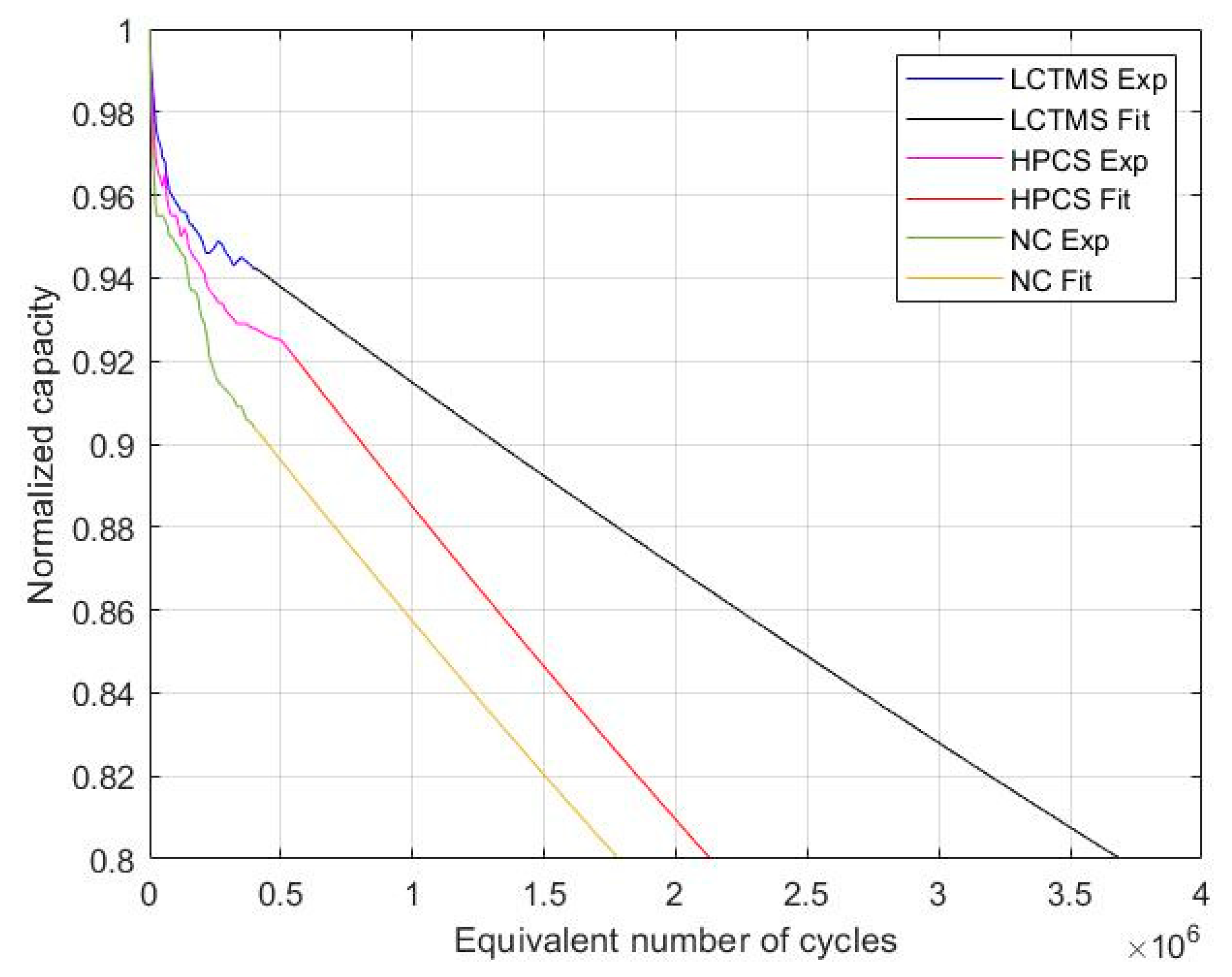
3.2. Capacity Degradation

The capacity degradation trend for three different case studies is shown in Figure 6. As is evident, capacity degradation depends on the temperature of the cell. The monitored temperature for the NC case study, the HPCS case study, and the LCTMS case study at the end of experimental test studies are 55.3, 48.8, and 32.5 °C, respectively. Therefore, a lower temperature is more favorable for a high current rate of 150 A charge/discharge load profile since cycling at such a low operating temperature exhibits better performance than higher working temperatures in terms of capacity degradation.
Considering the effects of temperature on the electrochemical performance of the cell components, it can be explained that the application of a more efficient TMS has decreased the operational temperature further and consequently the progression of disruptive mechanisms, which has led to lower capacity degradation within the performed cycles.
Moreover, the capacity degradation for the NC, HPCS, and LCTMS case studies are 90.4%, 92.5%, and 94.2%, respectively. This trend shows that using the passive cooling system (HPCS) as a proper TMS can significantly enhance the capacity retention around 2.1% for 4 × 10⁵ equivalent number of cycles. Moreover, employing the active cooling system (LCTMS) can improve the capacity retention up to 3.8% for 4 × 10⁵ equivalent number of cycles. The table proves that a robust active/passive TMS that can keep the temperature of the cell in a safe working limit is vital to extend the lifetime of the LiC technology. Table 4 lists the capacity degradation for three case studies.
Lifetime testing of LiCs under real-time conditions is impractical due to these energy storage systems’ long cycle life. Therefore, the best method based on an empirical approach would be testing the cell under different working conditions and estimating the end of life of the LiC using fitting techniques. The curve fitting techniques employ the cell’s current state to estimate the future state using different equations such as Gaussian, Fourier, the sum of sine, exponential, logarithmic, and polynomial equations. After fitting the degradation trend with the mentioned equations, the most trustable prediction trend should be selected for the degradation behavior’s future state.
There are two standard methods for curve fitting. The first method fits the curve based on all the experimental data from the first point to the endpoint, while the second method fits the curve on the part of a trend that the curve becomes stable. The first method is not practical since the fitted equation may mis-predict the end of life (EoL). The second method is more trustable because the predicted EoL would be based on the steady-state conditions. As shown in Figure 6, the LiC experiences two clear phases during the cycle aging tests. The first phase has a steep degradation trend when the capacity drops drastically in a short period. This could result from the loss of lithium inventory due to the initial solid electrolyte interface (SEI) formation at the electrode/electrolyte interface. Gassing formation is also reported to be one of the reasons for degradation in the LTO-based cells. The second phase is steadier, in which loss of active material and the loss of lithium inventory take control slowly, and the capacity degradation trend becomes linear. This phase is more favorable for the EoL estimation since the capacity degradation trend corresponds to the typical long-life cycle of lithium capacitors.
An exponential equation is used to predict the end of life degradation of the LiC. The MATLAB software is employed to fit the curve based on the averaged parameters a, b, and c. The parameters a and b are utilized to model the capacity degradation curve, and the parameter c is the constant term. The mathematical exponential equation explains the capacity fade characteristics of the LiC cell from the beginning of life (BoL) to the EoL. The exponential equation can be described as follows:
f ( x ) = a e b x + c
where the exponential equation coefficients with 95% confidence bounds are presented in Table 5.
The comprehensive experimental data from Figure 6 has been extended to the EoL degradation obtained from the curve fitting equation on the steady-state phase of the curve. A periodic exponential capacity degradation is revealed from Figure 7, fitted with the exponential capacity degradation equation, explained in equation 2. This trend is used for the life expectancy to estimate the end-of-life degradation of the LiC cell. The fitted curve and the predicted end of life degradation are exhibited in Figure 7. The experimental linear capacity degradation curve provided by the LiC manufacturer is in perfect match with the linear curve fitting of this work (for NC) [38]. Thus, it can be assumed that the longer lifetime claims for HPCS and LCTMS due to better thermal performance would match the reality accordingly.
The extrapolated EoL results are in accordance with what was observed from the experiment, and it could be explained that the temperature-dependent degradative mechanisms which had been started during the earlier cycles would happen further following the same trend within the upcoming cycles and the system in which the temperature is managed more efficiently would face slower capacity degradation and consequently can present a longer lifetime.
It is revealed from Figure 7 that EoL at 32.5 °C for 150 A charge/discharge cycle aging test in terms of capacity degradation is around 3.69 million eq-cycles. The LCTMS is used to maintain the temperature in such a good condition. For higher operating temperature at 48.8 °C, with the same load profile, the EoL in terms of capacity fade would be 2.13 million eq-cycles. The HPCS is employed to control the temperature in the desired range. Based on Table 6, if the cell is cycled under NC without using any cooling system, the cell’s temperature goes beyond the safe limit (55.3 °C). In such a harsh condition, the cell is degraded faster, and the lifetime would be jeopardized (1.78 million cycles).
In conclusion, the best operating temperature for the used load profile is 32.5 °C, which the lowest capacity fade can be observed. It is evident from the results that the end of life degradation in terms of capacity fade highlights the significance of controlling the temperature to extend the LiC cell lifetime. It can be concluded that by controlling the temperature of the cell at around 32.5 and 48.8 °C, the lifetime of the LiC would be extended by 51.7% and 16.5%, respectively, compared to the cycling of the LiC at 55.3 °C.

4. Conclusions

In this paper, an optimal TMS using a heat pipe cooling system (HPCS) has been developed for a prismatic 2300 F LiC technology to extend its lifetime and manage EoL degradation. The HPCS is able to control the temperature evolution of the cell during a 150 A charge/discharge current rate. Besides, a compact liquid-cooled TMS (LCTMS) was used to investigate the influence of temperature on LiC capacity fade. Three thermocouples (T1, T2, and T3) were employed to monitor the cell’s temperature. The cell was cycled in three different scenarios: under natural convection (NC), using HPCS, and using LCTMS.
The results demonstrate that the LiC cell temperature through the NC scenario reaches 55.3, 52.3, and 51.7 °C for T1, T2, and T3 thermocouples, respectively. For the second scenario using HPCS as the TMS, the T1 thermocouple reaches 48.8 °C, while T2 and T3 thermocouples show 47.5 and 48.4 °C, respectively. The third scenario (LCTMS) keeps the temperature around 32.5 °C. The monitored temperatures in the three scenarios prove the need for an optimal TMS to control the LiC temperature in the desired range and manage the cell’s life.
Furthermore, the capacity fade for the NC, HPCS, and LCTMS scenarios are measured 90.4%, 92.5%, and 94.2%, respectively, for 4 × 10⁵ equivalent number of cycles. This trend explains that employing the HPCS improves the capacity retention around 2.1% for 4 × 10⁵ equivalent number of cycles than the NC scenario. Besides, using the LCTMS enhances the capacity retention up to 3.8% for the same equivalent number of cycles. Estimation of the EoL degradation of the LiC was conducted using curve fitting techniques. Therefore, an exponential equation was employed to fit a curve based on the averaged parameters. At the end of the LiC cycle aging test, the fitted EoL in terms of capacity fade was 1.78 million cycles for the NC scenario. But EoL for HPCS and LCTMS scenarios was 2.13 and 3.69 million cycles, respectively, which proves that using a robust TMS can significantly extend the lifetime of the LiC by controlling the desired temperature range.
Future work should be adding the impact of the calendar life test to the cycling test for the LiC in different temperature conditions. This would be a time-consuming process since the degradation of the LiC by calendar test needs some years to be done.

Author Contributions

Conceptualization, methodology, software, validation, formal analysis, investigation, writing—original journal draft by D.K., writing, review and Editing by S.K., H.B. (Hamidreza Behi), H.B. (Hamidreza Beheshti), M.S.H., M.A., J.V.M.; supervision, writing—review and editing by M.B. All authors have read and agreed to the published version of the manuscript.

Funding

This research received no external funding.

Institutional Review Board Statement

Not applicable.

Informed Consent Statement

Not applicable.

Data Availability Statement

Not applicable.

Acknowledgments

The authors acknowledge JSR Micro NV for their support for this research and, also, Flanders Make for the support to our research group.

Conflicts of Interest

The authors declare no conflict of interest.

References

  1. Gandoman, F.H.; Behi, H.; Berecibar, M.; Jaguemont, J.; Aleem, S.H.E.A.; Behi, M.; van Mierlo, J. Chapter 16—Reliability evaluation of Li-ion batteries for electric vehicles applications from the thermal perspectives. In Uncertainties in Modern Power Systems; Zobaa, A.F., Abdel Aleem, S.H.E., Eds.; Academic Press: Cambridge, MA, USA, 2021; pp. 563–587. [Google Scholar] [CrossRef]
  2. Hosen, M.S.; Karimi, D.; Kalogiannis, T.; Pirooz, A. Electro-aging model development of nickel-manganese-cobalt lithium-ion technology validated with light and heavy-duty real-life profiles. J. Energy Storage 2020, 28, 101265. [Google Scholar] [CrossRef]
  3. Khaleghi, S.; Karimi, D.; Beheshti, S.H.; Hosen, M.S.; Behi, H.; Berecibar, M.; van Mierlo, J. Online health diagnosis of lithium-ion batteries based on nonlinear autoregressive neural network. Appl. Energy 2021, 282, 116159. [Google Scholar] [CrossRef]
  4. Behi, H.; Karimi, D.; Jaguemont, J.; Gandoman, F.H.; Khaleghi, S.; van Mierlo, J.; Berecibar, M. Aluminum heat sink assisted air-cooling thermal management system for high current applications in electric vehicles. In Proceedings of the 2020 AEIT International Conference of Electrical and Electronics Technology for Automotive, AEIT Automotive 2020, Turin, Italy, 18–20 November 2020. [Google Scholar] [CrossRef]
  5. Akbarzadeh, M.; Jaguemont, J.; Kalogiannis, T.; Karimi, D.; He, J.; Jin, L.; Xie, P.; van Mierlo, J.; Berecibar, M. A novel liquid cooling plate concept for thermal management of lithium-ion batteries in electric vehicles. Energy Convers. Manag. 2021, 231, 113862. [Google Scholar] [CrossRef]
  6. Soltani, M.; Beheshti, S.H. A comprehensive review of lithium ion capacitor: Development, modelling, thermal management and applications. J. Energy Storage 2021, 34, 102019. [Google Scholar] [CrossRef]
  7. Karimi, D.; Behi, H.; Hosen, M.S.; Jaguemont, J.; Berecibar, M.; van Mierlo, J. A compact and optimized liquid-cooled thermal management system for high power lithium-ion capacitors. Appl. Therm. Eng. 2021, 185, 116449. [Google Scholar] [CrossRef]
  8. Jaguemont, J.; Karimi, D.; van Mierlo, J. Optimal passive thermal management of lithium-ion capacitors for automotive applications. IEEE Trans. Veh. Technol. 2019, 168, 10518–10524. [Google Scholar] [CrossRef]
  9. Soltani, M.; Ronsmans, J.; Kakihara, S.; Jaguemont, J.; van den Bossche, P.; van Mierlo, J.; Omar, N. Hybrid battery/lithium-ion capacitor energy storage system for a pure electric bus for an urban transportation application. Appl. Sci. 2018, 8, 1176. [Google Scholar] [CrossRef] [Green Version]
  10. Ding, J.; Hu, W.; Paek, E.; Mitlin, D. Review of Hybrid Ion Capacitors: From Aqueous to Lithium to Sodium. Chem. Rev. 2018, 118, 6457–6498. [Google Scholar] [CrossRef]
  11. Hamidi, S.A.; Manla, E.; Nasiri, A. Li-ion batteries and Li-ion ultracapacitors: Characteristics, modeling and grid applications. In Proceedings of the 2015 IEEE Energy Conversion Congress and Exposition (ECCE), Montreal, QC, Canada, 20–24 September 2015; Institute of Electrical and Electronics Engineers Inc.: Montreal, QC, Canada, 2015; pp. 4973–4979. [Google Scholar] [CrossRef]
  12. Zhang, J.; Liu, X.; Wang, J.; Shi, J.; Shi, Z. Different types of pre-lithiated hard carbon as negative electrode material for lithium-ion capacitors. Electrochim. Acta 2016, 187, 134–142. [Google Scholar] [CrossRef]
  13. Fell, C.R.; Sun, L.; Hallac, P.B.; Metz, B.; Sisk, B. Investigation of the Gas Generation in Lithium Titanate Anode Based Lithium Ion Batteries. J. Electrochem. Soc. 2015, 162, A1916–A1920. [Google Scholar] [CrossRef]
  14. Huang, F.; Ma, J.; Xia, H.; Huang, Y.; Zhao, L.; Su, S.; Kang, F.; He, Y.B. Capacity Loss Mechanism of the Li4Ti5O12 Microsphere Anode of Lithium-Ion Batteries at High Temperature and Rate Cycling Conditions. ACS Appl. Mater. Interfaces 2019, 11. [Google Scholar] [CrossRef]
  15. Yang, Z.; Huang, Q.; Li, S.; Mao, J. High-temperature effect on electrochemical performance of Li4Ti5O12 based anode material for Li-ion batteries. J. Alloys Compd. 2018, 753, 192–202. [Google Scholar] [CrossRef]
  16. Handel, P.; Fauler, G.; Kapper, K.; Schmuck, M.; Stangl, C.; Fischer, R.; Uhlig, F.; Koller, S. Thermal aging of electrolytes used in lithium-ion batteries—An investigation of the impact of protic impurities and different housing materials. J. Power Sources 2014, 267, 255–259. [Google Scholar] [CrossRef]
  17. Smart, M.C.; Ratnakumar, B.V.; Whitacre, J.F.; Whitcanack, L.D.; Chin, K.B.; Rodriguez, M.D.; Zhao, D.; Greenbaum, S.G.; Surampudi, S. Effect of Electrolyte Type upon the High-Temperature Resilience of Lithium-Ion Cells. J. Electrochem. Soc. 2005, 152, A1096. [Google Scholar] [CrossRef]
  18. el Ghossein, N.; Sari, A.; Venet, P.; Genies, S.; Azaïs, P. Post-Mortem Analysis of Lithium-Ion Capacitors after Accelerated Aging Tests. J. Energy Storage 2021, 33, 102039. [Google Scholar] [CrossRef]
  19. Behi, H.; Behi, M.; Karimi, D.; Jaguemont, J.; Ghanbarpour, M.; Behnia, M.; Berecibar, M.; van Mierlo, J. Heat pipe air-cooled thermal management system for lithium-ion batteries: High power applications. Appl. Therm. Eng. 2020, 116240. [Google Scholar] [CrossRef]
  20. Karimi, D.; Behi, H.; Jaguemont, J.; el Baghdadi, M.; van Mierlo, J.; Hegazy, O. Thermal Concept Design of MOSFET Power Modules in Inverter Subsystems for Electric Vehicles. In Proceedings of the 2019 9th International Conference on Power and Energy Systems (ICPES), Perth, WA, Australia, 10–12 December 2019. [Google Scholar] [CrossRef]
  21. Soltani, M.; Berckmans, G.; Jaguemont, J.; Ronsmans, J.; Kakihara, S.; Hegazy, O.; van Mierlo, J.; Omar, N. Three dimensional thermal model development and validation for lithium-ion capacitor module including air-cooling system. Appl. Therm. Eng. 2019, 153, 264–274. [Google Scholar] [CrossRef]
  22. Möller, S.; Karimi, D.; Vanegas, O.; el Baghdadi, M.; Kospach, A.; Lis, A.; Hegazy, O.; Abart, C.; Offenbach, Â.B.Â. Application considerations for Double Sided Cooled Modules in Automotive Environment Double Sided Cooled Modules in Automotive Environment. In Proceedings of the 11th International Conference on Integrated Power Electronics Systems (CIPES), Berlin, Germany, 24–26 March 2020. [Google Scholar]
  23. Karimi, D.; Behi, H.; Jaguemont, J.; Sokkeh, M.A.; Kalogiannis, T.; Hosen, M.S.; Berecibar, M.; van Mierlo, J. Thermal performance enhancement of phase change material using aluminum-mesh grid foil for lithium-capacitor modules. J. Energy Storage 2020, 30. [Google Scholar] [CrossRef]
  24. Behi, H.; Karimi, D.; Behi, M.; Ghanbarpour, M.; Jaguemont, J.; Sokkeh, M.A.; Gandoman, F.H.; Berecibar, M.; van Mierlo, J. A new concept of thermal management system in Li-ion battery using air cooling and heat pipe for electric vehicles. Appl. Therm. Eng. 2020, 174. [Google Scholar] [CrossRef]
  25. Behi, H.; Karimi, D.; Gandoman, F.H.; Akbarzadeh, M.; Khaleghi, S.; Kalogiannis, T.; Hosen, M.S.; Jaguemont, J.; van Mierlo, J.; Berecibar, M. PCM assisted heat pipe cooling system for the thermal management of an LTO cell for high-current profiles. Case Stud. Therm. Eng. 2021, 25, 100920. [Google Scholar] [CrossRef]
  26. Behi, M.; Shakorian-poor, M.; Mirmohammadi, S.A.; Behi, H.; Rubio, J.I.; Nikkam, N.; Farzaneh-Gord, M.; Gan, Y.; Behnia, M. Experimental and numerical investigation on hydrothermal performance of nanofluids in micro-tubes. Energy 2020, 193, 116658. [Google Scholar] [CrossRef]
  27. Behi, H.; Ghanbarpour, M.; Behi, M. Investigation of PCM-assisted heat pipe for electronic cooling. Appl. Therm. Eng. 2017, 127, 1132–1142. [Google Scholar] [CrossRef]
  28. Behi, M.; Mirmohammadi, S.A.; Ghanbarpour, M.; Behi, H.; Palm, B. Evaluation of a novel solar driven sorption cooling/heating system integrated with PCM storage compartment. Energy 2018, 164, 449–464. [Google Scholar] [CrossRef]
  29. Behi, H. Experimental and Numerical Study on Heat Pipe Assisted PCM Storage System. Master’s Thesis, Royal Institute of Technology, Stockholm, Sweden, 2015. [Google Scholar]
  30. Behi, H.; Karimi, D.; Behi, M.; Jaguemont, J.; Ghanbarpour, M.; Behnia, M.; Berecibar, M.; van Mierlo, J. Thermal management analysis using heat pipe in the high current discharging of lithium-ion battery in electric vehicles. J. Energy Storage 2020, 32, 101893. [Google Scholar] [CrossRef]
  31. Behi, H.; Karimi, D.; Jaguemont, J.; Gandoman, F.H.; Kalogiannis, T.; Berecibar, M.; van Mierlo, J. Novel thermal management methods to improve the performance of the Li-ion batteries in high discharge current applications. Energy 2021, 120165. [Google Scholar] [CrossRef]
  32. Uno, M.; Kukita, A. Cycle Life Evaluation Based on Accelerated Aging Testing for Lithium-Ion Capacitors as Alternative to Rechargeable Batteries. IEEE Trans. Ind. Electron. 2016, 63, 1607–1617. [Google Scholar] [CrossRef]
  33. Gelman, A.; Imbens, G. Why High-Order Polynomials Should Not Be Used in Regression Discontinuity Designs. J. Bus. Econ. Stat. 2019, 37, 447–456. [Google Scholar] [CrossRef]
  34. Park, H.; Kim, M.; Xu, F.; Jung, C.; Hong, S.M.; Koo, C.M. In situ synchrotron wide-angle X-ray scattering study on rapid lithiation of graphite anode via direct contact method for Li-ion capacitors. J. Power Sources 2015, 283, 68–73. [Google Scholar] [CrossRef]
  35. Kariya, B.H.A. Development of an Air-Cooled, Loop-Type Heat Pipe with Multiple Condensers; Massachusetts Institute of Technology: Cambridge, MA, USA, 2012. [Google Scholar]
  36. Sheikholeslami, M.; Ganji, D.D. Heat transfer enhancement in an air to water heat exchanger with discontinuous helical turbulators; experimental and numerical studies. Energy 2016, 116, 341–352. [Google Scholar] [CrossRef]
  37. Sivakkumar, S.R.; Pandolfo, A.G. Evaluation of lithium-ion capacitors assembled with pre-lithiated graphite anode and activated carbon cathode. Electrochim. Acta 2012, 65, 280–287. [Google Scholar] [CrossRef]
  38. Principle and Features of Lithiumion Capacitormusashi Energy Solutions Co., Ltd., (n.d.). Available online: https://www.musashi-es.co.jp/en/lithium_ion_capacitor/whats/ (accessed on 29 April 2021).
Figure 1. The prismatic 2300 F LiC cell and HPCS with the dimensions.
Energies 14 02907 g001
Figure 2. The schematic of the experimental test bench for the LiC cell.
Energies 14 02907 g002
Figure 3. One period of the 150 A charge/discharge load profile to be used in the capacity degradation test.
Energies 14 02907 g003
Figure 4. The temperature variation of the LiC cell under NC at 23 °C initial temperature and 150 A charge/discharge current rate.
Energies 14 02907 g004
Figure 5. The temperature variation of the LiC cell employing HPCS as TMS at 23 °C initial temperature and 150 A charge/discharge current rate.
Energies 14 02907 g005
Figure 6. The LiC capacity fade in three case studies: without any TMS under NC, with HPCS, and with LCTMS.
Energies 14 02907 g006
Figure 7. Linear extrapolation for capacity fade in three case studies: without any TMS under NC, with HPCS, and with LCTMS.
Energies 14 02907 g007
Table 1. Thermo-physical properties of the LiC cell.
ParametersValueUnit
Capacitance2300F
Voltage range2.2 to 3.8V
Weight355grams
Current1–1000A
Energy density8Wh/kg
Width150mm
Height93mm
Thickness15.5mm
Operating temperature−30 to +70°C
Table 2. Thermo-physical properties of the utilized heat pipe.
ParametersValueUnit
Length250mm
Width11.2mm
Thickness3.5mm
Working fluidDistilled water-
Wick structureSintered-
Thermal conductivity8212W/m.K
Cooling power100W
Operating temperature30 to 120°C
Effective length125mm
Table 3. Temperature comparison of the LiC for two scenarios: without TMS and with HPCS.
ScenarioT1T2T3
Scenario 155.3 °C52.3 °C51.7 °C
Scenario 248.8 °C48.4 °C47.5 °C
Temperature reduction11.7%7.5%8%
Table 4. Capacity degradation for 4 × 10⁵ equivalent cycles for three case studies.
Case Study NameInitial TemperatureCell Temperature
after 1400 s
Capacity Degradation
for 4 × 10⁵ Eq-Cycles
NC23 °C55.3 °C90.4%
HPCS23 °C48.8 °C92.5%
LCTMS23 °C32.5 °C94.2%
Table 5. The parameters of the exponential equation for curve fitting.
Case Study Nameabc
NC0.9364−8.828 × 10−80.00001
HPCS0.9591−8.994 × 10−80.00835
LCTMS0.9615−4.984 × 10−80.00012
Table 6. Cycle aging end of life estimation for three case studies.
Case Study NameInitial TemperatureCell TemperatureCapacity EoL
NC23 °C55.3 °C1.78 × 106 eq-cycle
HPCS23 °C48.8 °C2.13 × 106 eq-cycle
LCTMS23 °C32.5 °C3.69 × 106 eq-cycle
Publisher’s Note: MDPI stays neutral with regard to jurisdictional claims in published maps and institutional affiliations.

