Article

Impact of Employing Hybrid Nanofluids as Heat Carrier Fluid on the Thermal Performance of a Borehole Heat Exchanger

by
Hossein Javadi
1,*,
Javier F. Urchueguia
1,
Seyed Soheil Mousavi Ajarostaghi
2 and
Borja Badenes
1
1
Information and Communication Technologies versus Climate Change (ICTvsCC), Institute of Information and Communication Technologies (ITACA), Universitat Politècnica de València (UPV), Camino de Vera s/n, 46022 Valencia, Spain
2
Department of Energy Conversion, Faculty of Mechanical Engineering, Babol Noshirvani University of Technology, Babol 47148-71167, Iran
*
Author to whom correspondence should be addressed.
Energies 2021, 14(10), 2892; https://doi.org/10.3390/en14102892
Submission received: 23 March 2021 / Revised: 8 May 2021 / Accepted: 13 May 2021 / Published: 17 May 2021
(This article belongs to the Special Issue Shallow Geothermal Energy 2021)

Abstract

:
In this numerical study, 4 types of hybrid nanofluid, including Ag-MgO/water, TiO2-Cu/water, Al2O3-CuO/water, and Fe3O4-multi-wall carbon nanotube/water, have been considered potential working fluid in a single U-tube borehole heat exchanger. The selected hybrid nanofluid is then analyzed by changing the volume fraction and the Reynolds number. Based on the numerical results, Ag-MgO/water hybrid nanofluid is chosen as the most favorable heat carrier fluid, among others, considering its superior effectiveness, minor pressure drop, and appropriate thermal resistance compared to the pure water. Moreover, it was indicated that all cases of Ag-MgO/water hybrid nanofluid at various volume fractions (from 0.05 to 0.20) and Reynolds numbers (from 3200 to 6200) could achieve better effectiveness and lower thermal resistances, but higher pressure drops compared to the corresponding cases of pure water. Nevertheless, all the evaluated hybrid nanofluids present lower coefficient of performance (COP)-improvement than unity which means that applying them as working fluid is not economically viable because of having higher pressure drop than the heat transfer enhancement.

1. Introduction

Shallow geothermal energy is one of the renewable and sustainable energy resources with numerous applications in different areas, such as heating and cooling of buildings, electricity production, agriculture, etc. The ground-source heat pump (GSHP) system is a promising technology in shallow geothermal energy exploitation [1]. In this system, the ground heat exchanger (GHE) is considered one of the main components that directly impacts the coefficient of performance of the GSHP. The GHE is classified into horizontal and vertical. The vertical GHE, also called borehole heat exchanger (BHE), has various configurations such as U-tube, W-tube, helix, and coaxial U-tube BHEs are found to be the most studied types [2].
Over the years different criteria and methods have been studied by researchers to design a more efficient GSHP system coupled to a BHE. The BHE overall length can be calculated by the American society of heating, refrigerating and air-conditioning engineers (ASHRAE) scheme where the working fluid temperature, borehole effective thermal resistance, building thermal load, and ground properties play a significant role in the BHE performance and coefficient of performance (COP) of the GSHP system. Philippe et al. [3] suggested a new method for designing single and multiple borefields, which was found to be in excellent agreement with commercial borehole sizing software. Fossa and Rolando [4] presented a precise and reliable technique for calculating the temperature penalty index, i.e., a parameter for BHE field design introduced in the ASHRAE. The total length of BHE and the temperature penalty term were estimated with high accuracy using the developed method. A simulation-based tool for designing the length of the BHE was compared to the ASHRAE design approach by Cullin et al. [5]. Based on the outcomes, the simulation-based tool (with an error of 6%) could estimate the BHE length with higher precision than the ASHRAE (with errors from −21% to 167%). Rolando et al. [6] proposed a g-function-based approach that could design the GSHP system considering various parameters, including temperature penalty term, thermal resistance, and building thermal load. Spitler and Bernier [7] reviewed different BHE design methods such as the ASHRAE method and g-function-based methods. It was concluded that despite presenting various techniques for designing the BHE, the lack of validation and comparison with experimental data still exists in the literature. Fossa and Rolando [8] proved their new technique consistency in designing the actual BHE field when different values have been selected for the building thermal load, ground properties, and the BHE length. Staiti and Angelotti [9] conducted a comparison between two different design procedures of BHE, including the ASHRAE method and the professional ground loop heat exchanger design software (GLHEPRO). According to the results, it was shown that the ASHRAE method overestimates the borehole size by 28% compared to that when using GLHEPRO. Fossa et al. [10] carried out a comparative analysis between different techniques such as the improved ASHRAE method, earth energy design (EED) code, and TecGeo proprietary code for predicting the total length of the BHE field over 10 years. It was indicated that the developed approach could estimate the BHE overall length with a percent error of 8% compared to the EED code as a reference. Further investigations can be found in the references of [11,12,13,14].
There have been many studies focusing on various methods to enhance the performance of BHEs [2,15,16,17,18,19,20]. Pure water is reported to be the most commonly applied working fluid in the BHEs [2]; nevertheless, nanofluids’ applications in the BHEs as working fluid has recently been under evaluation. Bobbo et al. [21] studied preliminarily and theoretically Al2O3/water nanofluid at different volume fractions to be used as a working fluid in the BHE. The results indicated that nanofluid use with a lower volume fraction is beneficial at higher temperatures for the system, but more analysis should be undertaken. The use of Al2O3/water nanofluid as a working fluid in a single U-tube BHE is theoretically conducted by Narei et al. [22]. Based on the results, the borehole depth decreases by 1.3% when using nanofluid instead of pure water. According to a comparison made numerically between the CuO/water and Al2O3/water nanofluids as the working fluids in the coaxial BHE, CuO/water nanofluid proved to have better potential in the heating operation of the system [23]. Sui et al. [24] analyzed the influence of using Al2O3/water nanofluid as a working fluid on the performance of a coaxial BHE numerically. It was shown that there could be more heat extraction (about 11%) when using Al2O3/water nanofluid than pure water. Diglio et al. [25] numerically investigated the addition of 7 nanoparticles, including SiO2, CuO, Cu, Al, Ag, graphite, and Al2O3, to the water to be used as the working fluid in the single U-tube BHE. The outcome demonstrated that the highest heat exchange rate and the highest decrease in the borehole thermal resistance is obtained by Ag/water and Cu/water nanofluids, respectively. A numerical study of Fe3O4/water and Al2O3/water nanofluids’ suspension stability in a coaxial BHE is conducted by Sun et al. [26]. It was suggested that in addition to the geometry optimization of the bottom of BHE, the pulsed fluid flow should be conducted to guarantee the tremendous operational reliability of the coaxial BHE. Peng et al. [27] evaluated Cu/water nanofluid in a single U-tube BHE at various volume fractions and nanoparticles’ size. It was illustrated that the performance of the BHE improves when using Cu/water nanofluid rather than pure water.
Moreover, there are a limited number of articles concerning the use of nanofluids in the horizontal GHE. The influence of using three nanofluids, including Al2O3/water, CuO/water, and SiO2/water as the working fluid in the horizontal GHE at different volume fractions is theoretically investigated by Mishra et al. [28]. Based on the results, the use of CuO/water nanofluid at a 4% volume fraction leads to the highest heat exchange rate than that of 2 other nanofluids. Du et al. [29,30] experimentally and numerically studied the effect of using CuO/water nanofluid as a working fluid in 2 double U-tube horizontal GHE. It was concluded that the heat exchange rate could be enhanced by up to 40% by CuO/water nanofluid compared with pure water. They also reported that the best nanoparticle diameter and shape are 40 nm and sphere, respectively.
Further research on the nanofluids has resulted in the invention of a new type of nanofluid, i.e., hybrid nanofluids, which can be generated by dispersing 2 or more nanoparticles into the base fluid. Since the simple nanofluids do not possess any desirable feature necessary for a particular objective, they are likely to lack either rheological or thermal properties. In contrast, the chemical and physical properties of hybrid nanofluids are provided in a homogeneous phase by a simultaneous combination of added nanoparticles’ properties to the base fluid. Considering that one of the essential criteria in actual projects is the tradeoff between various characteristics, the significant role of hybrid nanofluids can be indicated. Hybrid nanofluids generally have superior chemical stability, thermal conductivity, mechanical resistance, physical strength, etc., than simple nanofluids [31,32,33,34,35,36,37]. Suresh et al. [38] analyzed the application of Al2O3-Cu/water hybrid nanofluid experimentally in a straight tube at fixed heat flux. Labib et al. [39] simulated Al2O3-carbon nanotube (CNT)/water hybrid nanofluid in a horizontal straight tube under the tube wall’s constant heat flux. Numerical simulation of the laminar flow of Al2O3-Cu/water hybrid nanofluid inside a corrugated box with a fixed heat source is carried out by Takabi and Salehi [40]. Sundar et al. [41] experimentally evaluated Fe3O4-multi-wall CNT (MWCNT)/water hybrid nanofluid flowing through a horizontal straight tube at fixed heat flux. The impact of using TiO2-Cu/water hybrid nanofluid on the performance of a tubular heat exchanger is examined experimentally by Madhesh et al. [42]. An experimental investigation on Graphene nanoplatelet-Ag/water hybrid nanofluid application in a horizontal straight tube under constant heat flux is conducted by Yarmand et al. [43]. The influence of different volume fractions on the thermophysical properties of Ag-MgO/water hybrid nanofluid is experimentally investigated by Esfe et al. [44]. Toghraie et al. [45] added ZnO and TiO2 nanoparticles experimentally to ethylene glycol (EG) and studied the effects of various volume fractions and temperatures on the thermal conductivity of the hybrid nanofluid. Van Trinh et al. [46] also conducted an experiment in which 3 nanoparticles, such as graphene, MWCNT, and Cu are combined with EG and then examined the effect of different volume fractions. In an experimental investigation done by Sundar et al. [47], the dispersion of Co3O4 and graphene oxide nanoparticles into EG, water, and a mixture of water/EG are evaluated at various temperatures and volume fractions. Sahoo and Sarkar [48] numerically studied the addition of TiO2, SiC, CuO, Cu, Al2O3, and Ag to EG to be used as a coolant in an automobile radiator. Mousavi Ajarostaghi et al. [49] compared numerically 2 types of hybrid nanofluid including Ag-Hydrogen Exfoliated Graphene (HEG)/water and Fe3O4-MWCNT/water at different volume fractions in a straight tube which was equipped with a turbulator. Hashemi Karouei et al. [50] evaluated the laminar heat transfer and the use of hybrid nanofluids (Fe3O4-MWCNT/water and Ag-HEG/water) in a helical double pipe heat exchanger equipped with a new helical turbulator. Moreover, in addition to the aforementioned works, some other studies have proven that numerical simulation is an efficient method to evaluate utilizing different nanofluids (single or hybrid) in various applications [51,52,53].
Given the literature reviewed and to the best of our knowledge, it is necessary to highlight that there has been no previous study yet reported on using any hybrid nanofluids as the working fluid in the BHEs. Hence, this research work aims at the numerical investigation of comparing 4 types of hybrid nanofluids, including Ag-MgO/water, TiO2-Cu/water, Al2O3-CuO/water, and Fe3O4-MWCNT/water as a working fluid in a single U-tube BHE. Then, the selected hybrid nanofluid is evaluated at various volume fractions. After that, the impact of an increase in the Reynolds number of hybrid nanofluid on the BHE thermal performance is studied.

2. Geometry and Boundary Conditions

In this research, a three-dimensional unsteady state numerical model of a single U-tube BHE is built and analyzed by Ansys Fluent commercial software, which uses the finite volume method. Figure 1 shows the schematics of the BHE under study and indicates its different regions. Geometric and operating parameters and study variables are demonstrated in Table 1. The thermo-physical properties of the U-tube, casing, backfill, and the surrounding soil are given in Table 2. The casing is placed between the backfill and soil, and note that the borehole depth and the U-tube length are the same. As shown in Figure 1, the U-tube and casing materials are considered to be polyethylene (PE) and steel, respectively. Moreover, the backfill material is silica sand, and the soil around the BHE comprises 2 parts, including clay (L1) and sandy-clay (L2). In this study, 4 types of hybrid nanofluids are evaluated to be applied as working fluids in a single U-tube BHE. Eight nanoparticles, such as Ag, Al2O3, Cu, CuO, MgO, MWCNT, TiO2, and Fe3O4 have been dispersed equally into the water to create 4 types of hybrid nanofluid of Ag-MgO (50:50 vol.%)/water, TiO2-Cu (50:50 vol.%)/water, Al2O3-CuO (50:50 vol.%)/water, and Fe3O4-MWCNT (50:50 vol.%)/water. Thermo-physical properties of the base fluid and nanoparticles are presented in Table 3. The BHE operates 24 h a day in the cooling mode where the inlet temperature is set to 300.15 K. The velocity inlet and pressure outlet are chosen for the inlet and outlet boundary conditions, respectively. The standard k-epsilon model is selected for the turbulent fluid flow inside the U-tube, and for the velocity-pressure condition, we applied the SIMPLE algorithm. The time step size is 60 s. The relaxation factors in the spatial discretization of momentum and energy equations done by second-order upwind are 0.7 and one, respectively. Considering the residuals of 10−6 for energy equation and 10−3 for k, epsilon, momentum, and continuity equations, the numerical simulations’ convergence has been achieved.

3. Thermo-Physical Properties and Studied Factors

The conservation equations for energy, momentum, and continuity are given below:
ρ t + · ( ρ ν ) = S m
( ρ ν ) t + · ( ρ ν ν ) = P + ( τ = ) + ρ g + F , τ = = μ ν + ν T 2 3 · ν I
( ρ E ) t + · ( ν ( ρ E + P ) ) = k H N F T j h j J j + ( τ = H N F · ν ) + S h
The thermo-physical properties of hybrid nanofluid can be estimated with the following equations.
The density of hybrid nanofluid (ρHNF) [55]:
ρ H N F = ϕ N P 1 ρ N P 1 + ϕ N P 2 ρ N P 2 + ( 1 ϕ N P 1 ϕ N P 2 ) ρ B F
The specific heat capacity of hybrid nanofluid ((Cp)HNF) [55]:
( C p ) H N F = ϕ N P 1 ( ρ C p ) N P 1 + ϕ N P 2 ( ρ C p ) N P 2 + ( 1 ϕ N P 1 ϕ N P 2 ) ( ρ C p ) B F ρ H N F
The thermal conductivity of hybrid nanofluid (kHNF) [55]:
k H N F = 2 ϕ N P 1 k N P 1 + ϕ N P 2 k N P 2 2 k B F ϕ N P 1 + ϕ N P 2 + 2 k B F + ϕ N P 1 k N P 1 + ϕ N P 2 k N P 2 ϕ N P 1 + ϕ N P 2 ϕ N P 1 k N P 1 + ϕ N P 2 k N P 2 k B F ϕ N P 1 + ϕ N P 2 + 2 k B F + ϕ N P 1 k N P 1 + ϕ N P 2 k N P 2 ϕ N P 1 + ϕ N P 2
The viscosity of hybrid nanofluid (μHNF) [55]:
μ H N F = μ B F ( 1 ϕ N P 1 ϕ N P 2 ) 2.5
The thermal expansion of hybrid nanofluid (βHNF) [55]:
β H N F = ϕ N P 1 ( ρ β ) N P 1 + ϕ N P 2 ( ρ β ) N P 2 + ( 1 ϕ N P 1 ϕ N P 2 ) ( ρ β ) B F ρ H N F
The subscripts of HNF, BF, NP1, and NP2 indicate hybrid nanofluid, base fluid, nanoparticle 1, and nanoparticle 2. ϕ represents the volume fraction of nanoparticles. It should be emphasized that an equal volume of 8 nanoparticles has been dispersed into the base fluid, which resulted in the formation of 4 types of hybrid nanofluid (see Table 1).
Factors under study in this work include the pressure drop, thermal resistance, and effectiveness, as follows:
The pressure drop of working fluid flows through the U-tube (ΔP) [18]:
Δ P = P 1 P 2
P1 is the inlet pressure (Pa), and P2 is the outlet pressure (Pa).
The total thermal resistance of the borehole and the surrounding soil (R) [18]:
R = T s T a Q H
Ts and Ta indicate the surrounding soil’s initial temperature (K) and working fluid’s average temperature between inlet and outlet (K), respectively. QH is the heat exchange rate per unit BHE depth, which is calculated by dividing Q (heat exchange rate, W) by H (BHE depth, m) [18]:
Q H = Q H , w h e r e Q = m ˙ C p ( T 1 T 2 )
Furthermore, m ˙ and Cp show the mass flow rate (kg/s) and the specific heat capacity (J/kg·K) of the working fluid, respectively. T1 is the inlet temperature (K) and T2 is the outlet temperature (K). Besides, the effectiveness is considered as a non-dimensional factor for evaluating the heat transfer efficiency of the BHE changing from 0 to 1 [18]:
E = Q R e a l Q M A X = m ˙ C p ( T 1 T 2 ) m ˙ C p ( T 1 T s ) = ( T 1 T 2 ) ( T 1 T s )
QReal and QMAX demonstrate the real heat exchange rate and the highest heat exchange rate, respectively. COP improvement (η) factor considers the impact of applying the hybrid nanofluids on the BHE operation in terms of both pressure drop and heat transfer [49,56]:
η = N u N u 0 f 0 f 1 / 3
The subscript of 0 refers to pure water as a working fluid at the Reynolds number of 3200 in Section 5.1 and Section 5.2, and the cases of pure water at each specific Reynolds number considered in Section 5.3. Nu and f are Nusselt number and friction factor which are defined as follows, respectively [49,56]:
N u = h a d h k
f = 2 d h Δ P ρ u 2 l
ha and dh are the average heat transfer coefficient (W/m2·K) and the U-tube hydraulic diameter (m), respectively. u is the working fluid velocity (m/s), and l is the length of the U-tube (m).

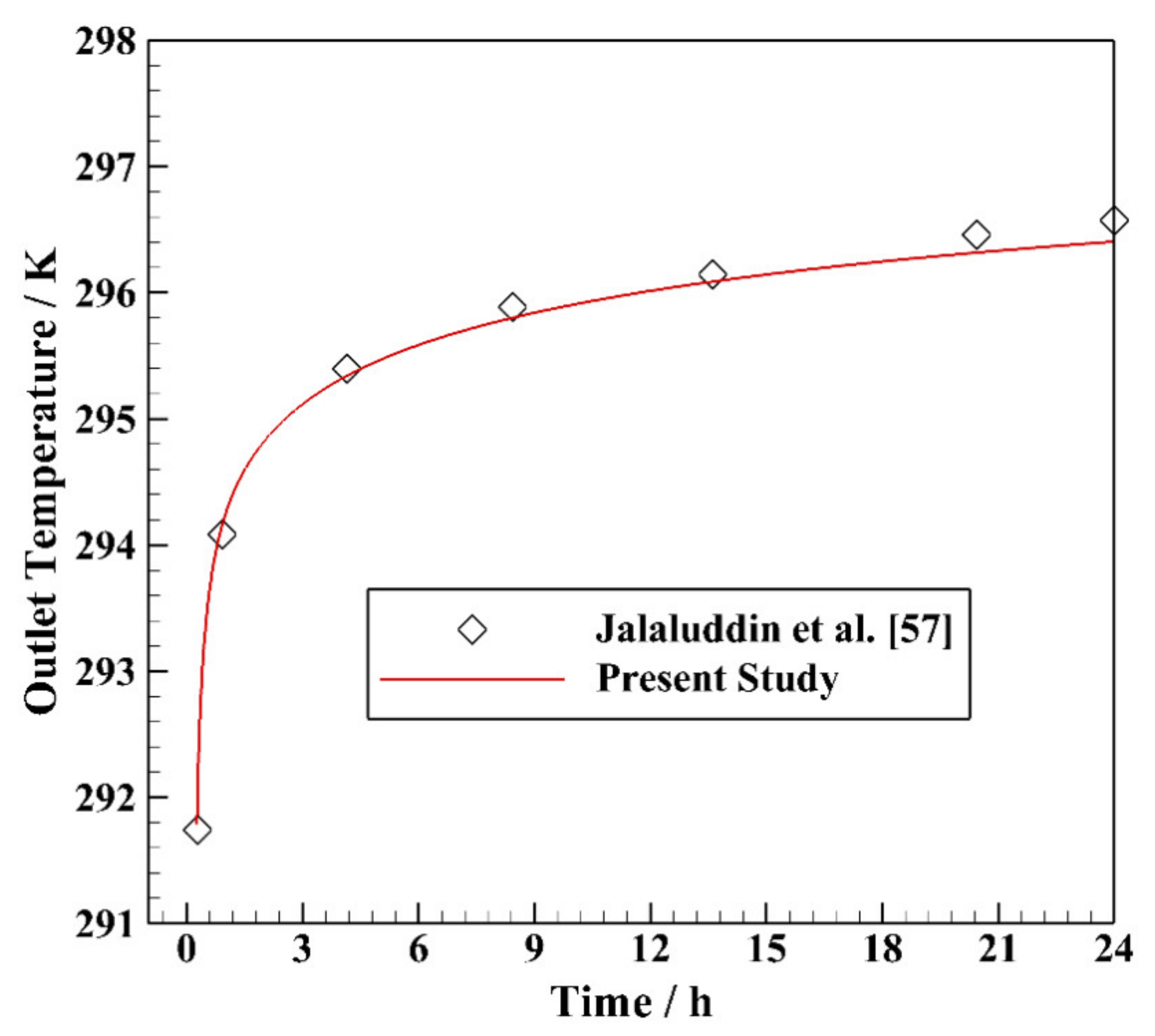
4. Mesh Topology and Validation

The generated grid for the single U-tube BHE is illustrated in Figure 2a,b. As can be seen, the working fluid and U-tube meshing are done by structured methods, while the other regions are meshed by the unstructured methods. Because the volumes inside the borehole are of high importance compared to the outside, finer grids have been applied for these regions. Besides, the boundary layer meshes are generated for the interfaces between the working fluid and U-tube as well as the U-tube and backfill, with 3 layers and a growth rate of 1.2. The grid independence test of the model is also conducted, as shown in Figure 2c. Different numbers of grids, from 334,473 to 2,129,847, have been evaluated for the model in terms of the working fluid’s outlet temperature. The third type of mesh with the orthogonal quality of 0.22, skewness of 0.82, and the grid number of 1,573,132 is chosen for the numerical modeling of hybrid nanofluids in the BHE. This numerical study is verified with an experiment conducted in Japan by Jalaluddin et al. [57] (see Figure 3). All the geometric parameters and test conditions are similar to what is stated in Section 2, except for the borehole depth and soil diameter, 20 m and 10 m, respectively, with the pure water flowing through the U-tube. It is shown that there is an excellent agreement between the numerical results and the experimental data verifying the reliability of the numerical model being studied.

5. Results and Discussion

In this study, several types of hybrid nanofluids such as Ag-MgO/water, Al2O3-CuO/water, Fe3O4-MWCNT/water, and TiO2-Cu/water are numerically examined to be used as working fluid in a single U-tube BHE. After comparing, the selected hybrid nanofluid is evaluated at various values of volume fractions and Reynolds numbers. Also, the obtained numerical results of hybrid nanofluids have been compared with the case of pure water.

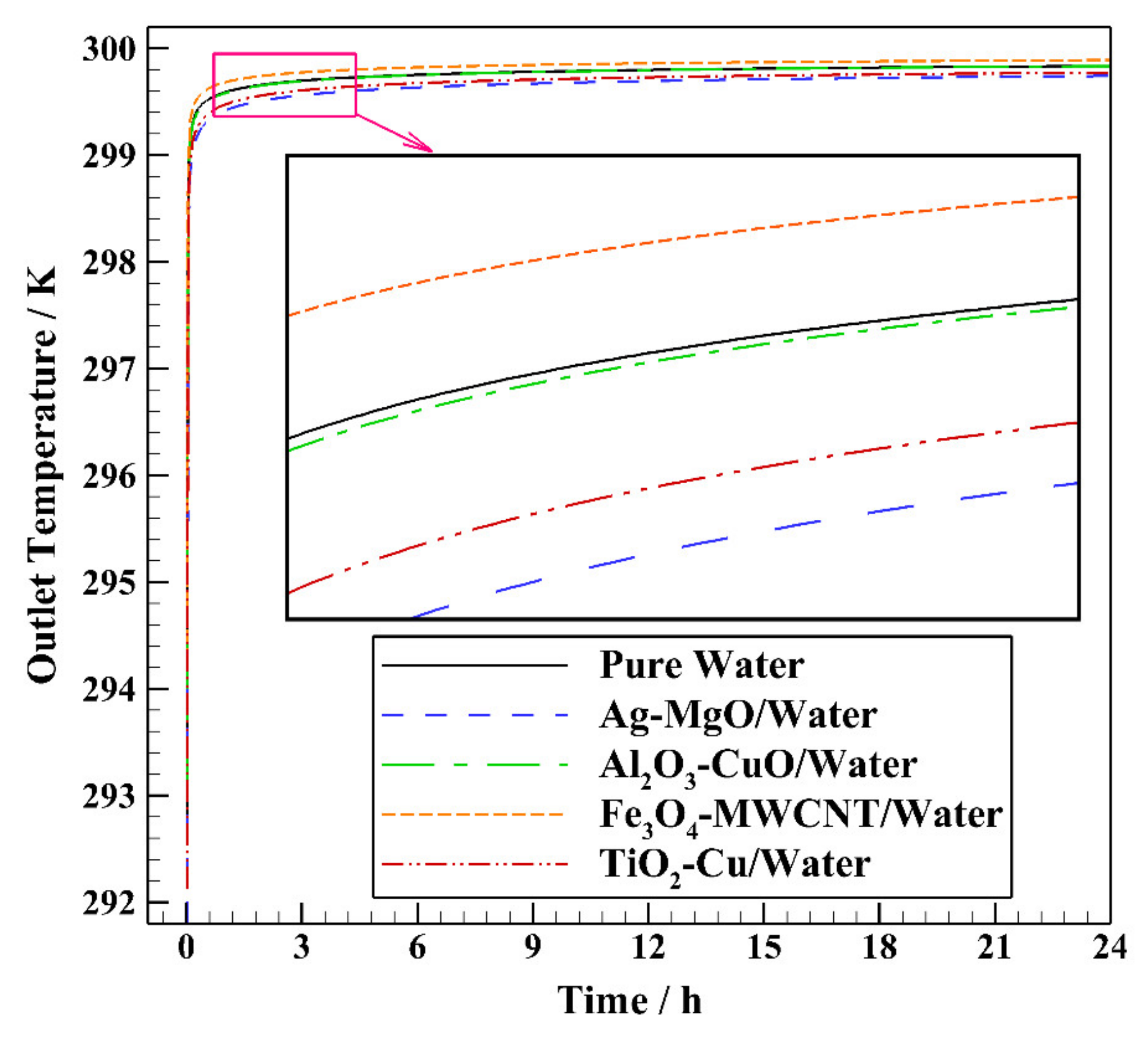
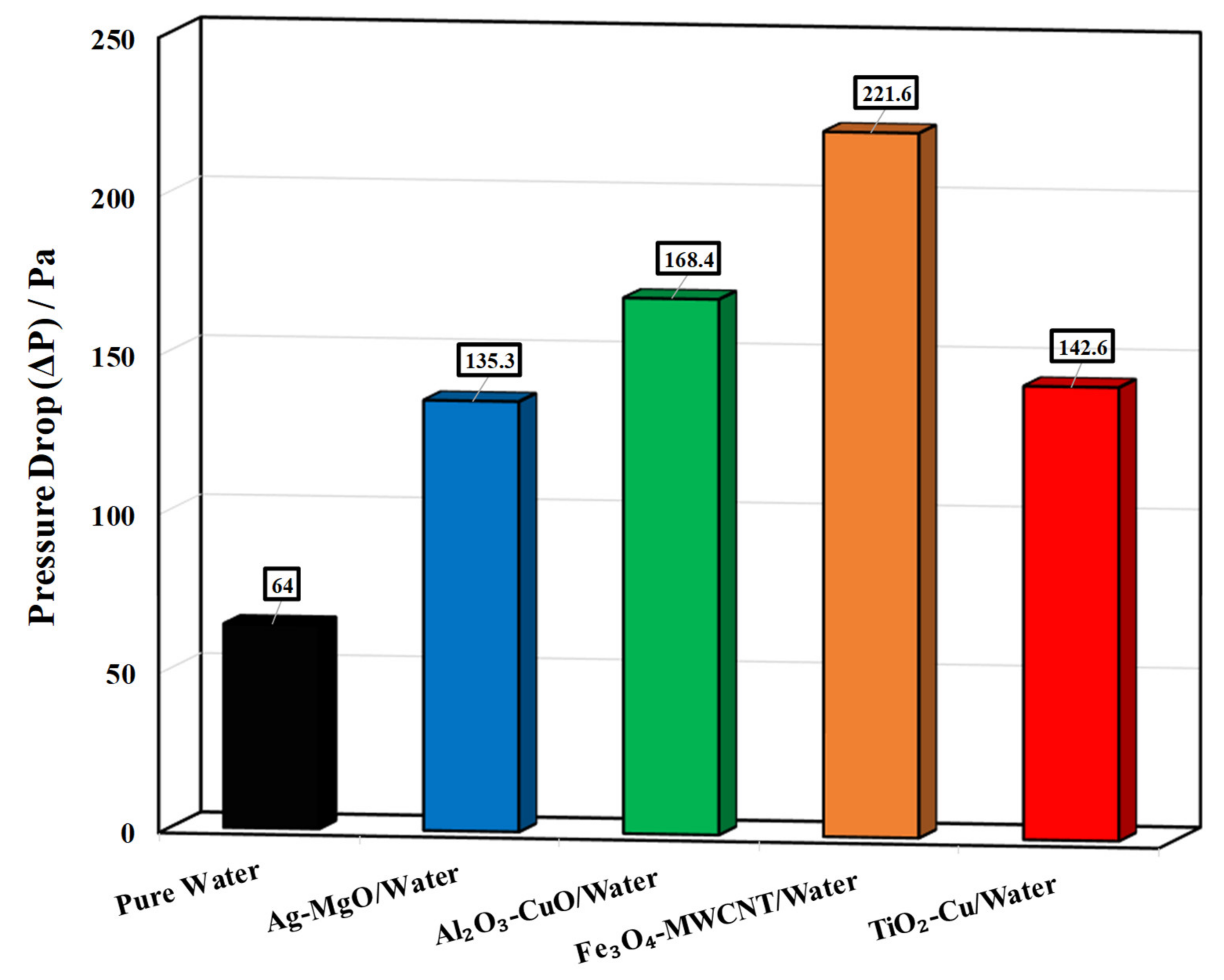
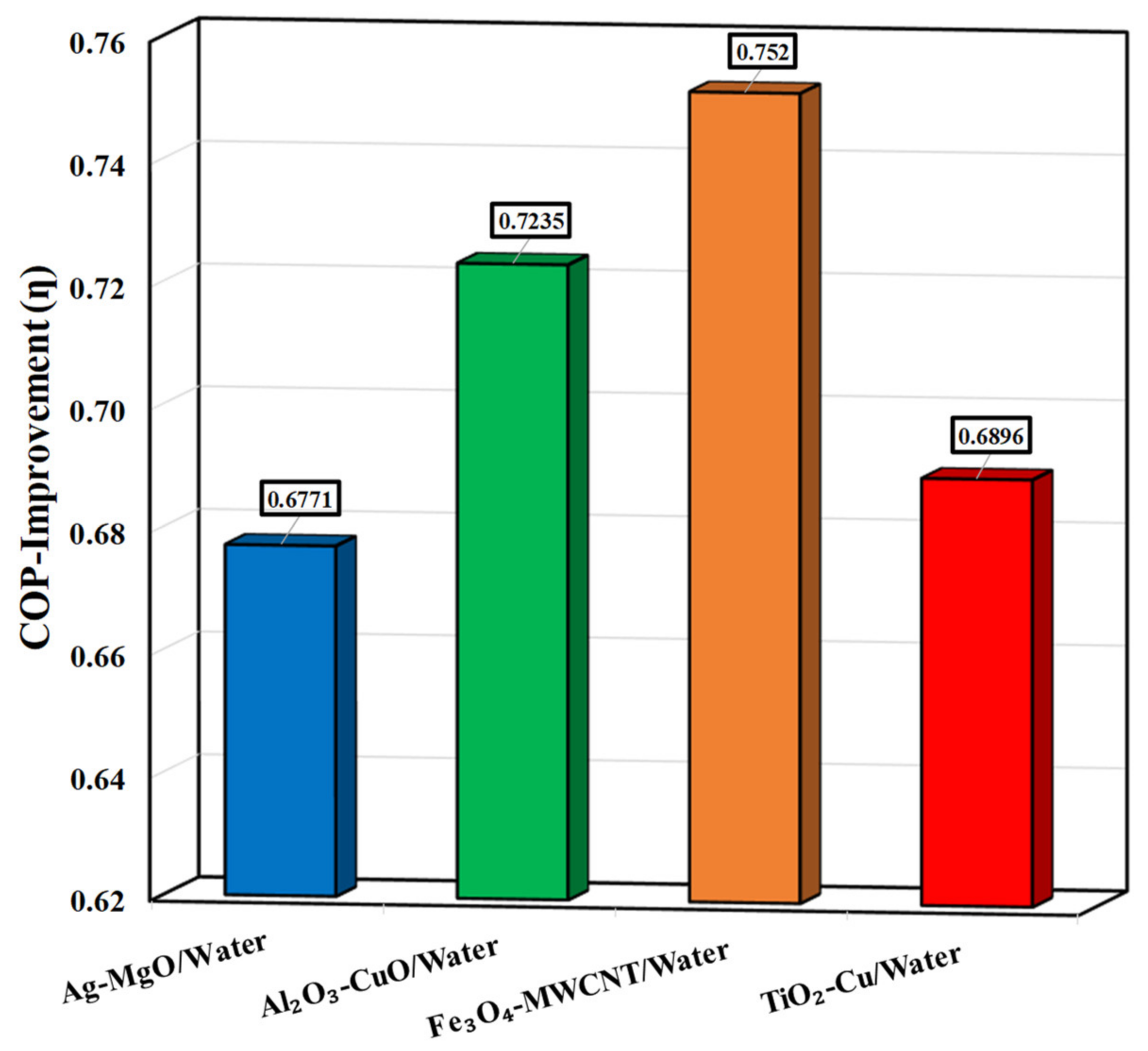
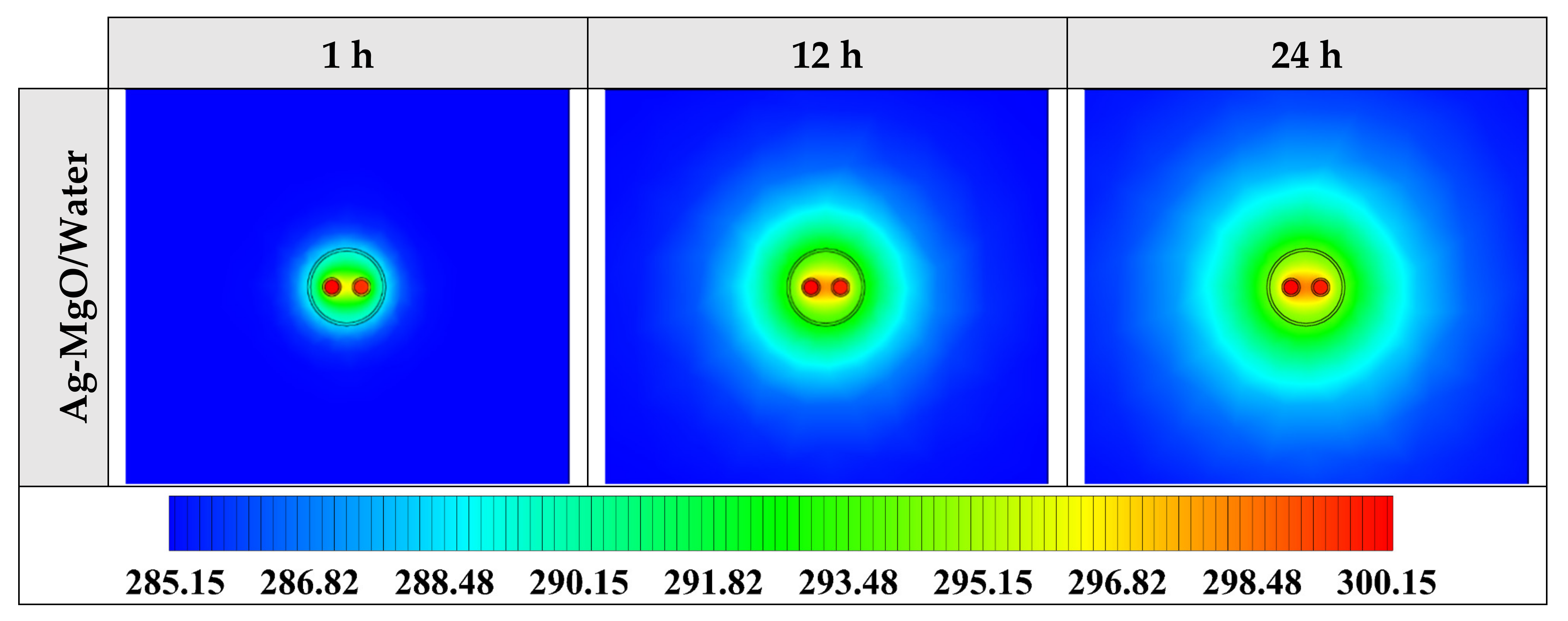
5.1. Comparing Various Types of Hybrid Nanofluid

Thermo-physical properties of various hybrid nanofluids at ϕ = 0.15 calculated by Equations (4)–(8) are given in Table 4. The variation of the outlet temperature with operating time using various hybrid nanofluids at ϕ = 0.15 and Re = 3200 is illustrated in Figure 4. Accordingly, it can be seen that at the beginning of the operation, the differences between the various cases are not notable. However, all hybrid nanofluids show lower outlet temperature than pure water, except for Fe3O4-MWCNT/water. Moreover, the results show that the lowest outlet temperature belongs to the case with Ag-MgO/water hybrid nanofluid followed by TiO2-Cu/water hybrid nanofluid.
The effectiveness (E) for various hybrid nanofluids at ϕ = 0.15 and Re = 3200 is depicted in Figure 5. It can be concluded that the hybrid nanofluids have higher effectiveness than pure water, while the corresponding value for Fe3O4-MWCNT/water is lower than pure water. For instance, the effectiveness of cases with Ag-MgO/water, Al2O3-CuO/water, and TiO2-Cu/water are 29.81, 0.48, and 19.71% more than pure water; however, the effectiveness of Fe3O4-MWCNT/water is lower by 17.79%. According to Equation (12), the effectiveness is the ratio of the real heat exchange rate to the highest heat exchange rate. Since the mass flow rate and the specific heat capacity are simplified in the numerator and denominator of the fraction, they do not influence the estimated effectiveness. Therefore, the inlet and outlet temperature difference plays the primary role here (see Figure 4 and Figure 5). The total thermal resistance of the borehole and the surrounding soil and the heat exchange rate per unit BHE depth for various hybrid nanofluids at ϕ = 0.15 and Re = 3200 are shown in Figure 6.
Figure 6 shows that all hybrid nanofluids being studied have lower thermal resistance and higher heat exchange rate per unit BHE depth than the pure water as the working fluid. Consequently, hybrid nanofluids’ thermal resistances, including Ag-MgO/water, Al2O3-CuO/water, Fe3O4-MWCNT/water, and TiO2-Cu/water, are less than pure water by 1.35, 1.41, 1.47, and 1.35%, respectively. Furthermore, it can be seen that the differences between the calculated thermal resistance of various hybrid nanofluids are not considerable. However, the lowest one belongs to the case with Fe3O4-MWCNT/water working fluid. The thermal resistance and the heat exchange rate per unit BHE depth have been calculated by Equations (10) and (11). In these equations, the specific heat capacity and the density of the hybrid nanofluids significantly impact the estimated results. For instance, Fe3O4-MWCNT/water has the minimum effectiveness, but it could achieve the highest heat exchange rate, which can be related to its higher values of specific heat capacity and thermal conductivity compared to the others (see Table 4 and Figure 5 and Figure 6).
The pressure drop for various hybrid nanofluids at ϕ = 0.15 and Re = 3200 is illustrated in Figure 7. It is indicated that using hybrid nanofluid instead of pure water as a working fluid results in higher rates of pressure drop. The pressure drops of hybrid nanofluids, including Ag-MgO/water, Al2O3-CuO/water, Fe3O4-MWCNT/water, and TiO2-Cu/water, are higher than pure water by 111.41, 163.12, 246.25, and 122.8%, respectively. The maximum and minimum values of pressure drop among hybrid nanofluids belong to the cases with Fe3O4-MWCNT/water and Ag-MgO/water, respectively.
COP improvement for various hybrid nanofluids at ϕ = 0.15 and Re = 3200 is presented in Figure 8. COP improvement factor is an efficient index that is calculated by Equation (13). In this factor, both the ratios of friction factor (or pressure drop) and average Nusselt number are considered in which higher COP improvement values (more than unity; η > 1) mean that the proposed method is efficient in terms of pressure drop and heat transfer. From Figure 8, it can be seen that all the evaluated hybrid nanofluids present lower COP improvement than unity which means that applying them as working fluid is not economically viable because of having higher pressure drop (or friction factor) than heat transfer enhancement. As a result, it can be concluded that the COP improvement of the evaluated hybrid nanofluids, including Ag-MgO/water, Al2O3-CuO/water, Fe3O4-MWCNT/water, and TiO2-Cu/water, is lower than pure water by 32.29, 27.65, 24.8, and 31.04%, respectively. The lowest and the highest COP improvement values belong to the cases with Ag-MgO/water and Fe3O4-MWCNT/water hybrid nanofluids, respectively. To see better the heat transfer process in the proposed system, 2D contours of the temperature distribution of the BHE using Ag-MgO/water hybrid nanofluid at various operating hours are illustrated in Figure 9 when ϕ = 0.15 and Re = 3200 (top view at Z = 0). It is worth mentioning that since the contours of various hybrid nanofluids have not demonstrated the differences in various cases appropriately, only the contours of the selected hybrid nanofluid are presented here. As can be seen, the thermal radius around the borehole increases continuously by exchanging heat from the working fluid to the surroundings.

5.2. Impact of Volume Fraction of Hybrid Nanofluid

In the second section, the impact of the volume fraction of hybrid nanofluids on the thermal performance of the BHE is performed. It should be noted that the Ag-MgO/water hybrid nanofluid is considered a working fluid, considering its superior effectiveness, minor pressure drop, and appropriate thermal resistance among studied hybrid nanofluids. Therefore, in the present study, the primary criterion for selecting the best hybrid nanofluid is the thermal improvement called effectiveness (see Equation (12)). 4 volume fractions of nanofluids such as 0.05, 0.10, 0.15, and 0.20 are chosen. Also, like Section 5.1, the numerical results of Ag-MgO/water hybrid nanofluid with various volume fractions are compared with the case of pure water. Note that the thermo-physical properties of Ag-MgO/water hybrid nanofluid at different volume fractions have been estimated by Equations (4)–(8) (see Table 5).
Figure 10 shows the variation of the outlet temperature with operating time using Ag-MgO/water hybrid nanofluid with various volume fractions at Re = 3200. It can be recognized that, first, the differences between the various cases are not noteworthy. Nevertheless, then, the cases with Ag-MgO/water hybrid nanofluids at various volume fractions display lower outlet temperature than the case of pure water. Moreover, the results show that the lowest outlet temperature is achieved by the case containing Ag-MgO/water hybrid nanofluid at ϕ = 0.10, followed by the case at ϕ = 0.15.
The effectiveness (E) for Ag-MgO/water hybrid nanofluid with various volume fractions at Re = 3200 is shown in Figure 11. It is illustrated that Ag-MgO/water hybrid nanofluid at each value of volume fraction presents more effectiveness than pure water. Also, the effectiveness of cases with ϕ = 0.05, 0.1, 0.15, and 0.2 are more than pure water by 28.36%, 37.02%, 29.81%, and 11.54%, respectively. Accordingly, among the volume fractions under study of Ag-MgO/water hybrid nanofluid, the maximum effectiveness belongs to the case with ϕ = 0.1, and the case with ϕ = 0.15 is positioned at the second level. As indicated in Figure 10 and Figure 11, Ag-MgO/water hybrid nanofluid’s outlet temperature and effectiveness at a volume fraction of 0.20 are found to be higher and lower than that for the other cases, respectively. This matter can be related to a decrease of almost 58% in the specific heat capacity of Ag-MgO/water hybrid nanofluid when the volume fraction changes from 0.05 to 0.20; although the thermal conductivity is improved by 55% (see Table 5). Based on Equation (12), the effectiveness is estimated by dividing the real heat exchange rate by the highest heat exchange rate. Because the mass flow rate and the specific heat capacity have been simplified in the numerator and denominator of the fraction, they do not affect the effectiveness obtained. Hence, the most important parameter here is the temperature difference between the inlet and outlet (see Figure 10 and Figure 11).
The total thermal resistance of the borehole and the surrounding soil and the heat exchange rate per unit BHE depth for Ag-MgO/water hybrid nanofluid with various volume fractions at Re = 3200 are illustrated in Figure 12. As shown, Ag-MgO/water hybrid nanofluid at the considered volume fractions achieves lower thermal resistance and higher heat exchange rate per unit BHE depth than pure water. Consequently, the thermal resistances of cases with ϕ = 0.05, 0.1, 0.15, and 0.2 are lower than pure water by 0.88%, 1.14%, 1.35%, and 1.55%, respectively, which are not considerable. However, the lowest one belongs to the case of ϕ = 0.2.
The thermal resistance and the heat exchange rate per unit BHE depth are estimated by Equations (10) and (11). The calculated results have been under the direct influence of the hybrid nanofluids’ specific heat capacity and density. Subsequently, the Ag-MgO/water hybrid nanofluid at ϕ = 0.20 has the lowest effectiveness but the highest heat exchange rate, which can be explained by its higher values of density and thermal conductivity compared to the other cases (see Table 5 and Figure 11 and Figure 12). The pressure drop for Ag-MgO/water hybrid nanofluid with various volume fractions at Re = 3200 is presented in Figure 13. This figure indicates that using the Ag-MgO/water hybrid nanofluid at each value of volume fraction instead of pure water causes higher rates of pressure drop. The pressure drops of Ag-MgO/water hybrid nanofluid at ϕ = 0.05, 0.1, 0.15, and 0.2 are higher than the pure water by 5.47%, 37.97%, 111.41%, and 275.94%, respectively. Furthermore, as the volume fraction increases from 0.05 to 0.2 (by 300% growth), the pressure drop rises by 256.44%.
Figure 14 depicts that Ag-MgO/water hybrid nanofluid with each value of volume fraction shows lower COP improvement than unity, indicating that the studied cases are not economically viable as they cause more pressure drop (or friction factor) than heat transfer augmentation. Consequently, it can be concluded that the COP improvement of the evaluated cases with various volume fractions including ϕ = 0.05, 0.10, 0.15, and 0.20 is lower than pure water by 23.26%, 28.82%, 32.29%, and 34.29%, respectively. In terms of COP improvement, the case with Ag-MgO/water hybrid nanofluid at ϕ = 0.05 could obtain the maximum value of almost 0.77. To see the heat exchange in the BHE containing Ag-MgO/water hybrid nanofluid at ϕ = 0.10 and Re = 3200, 2D contours of the temperature at different hours of operating (top view at Z = 0) are shown in Figure 15. This shows that using Ag-MgO/water hybrid nanofluid with the volume fraction fixed at 0.10 results in better temperature distribution and more heat transfer rate.

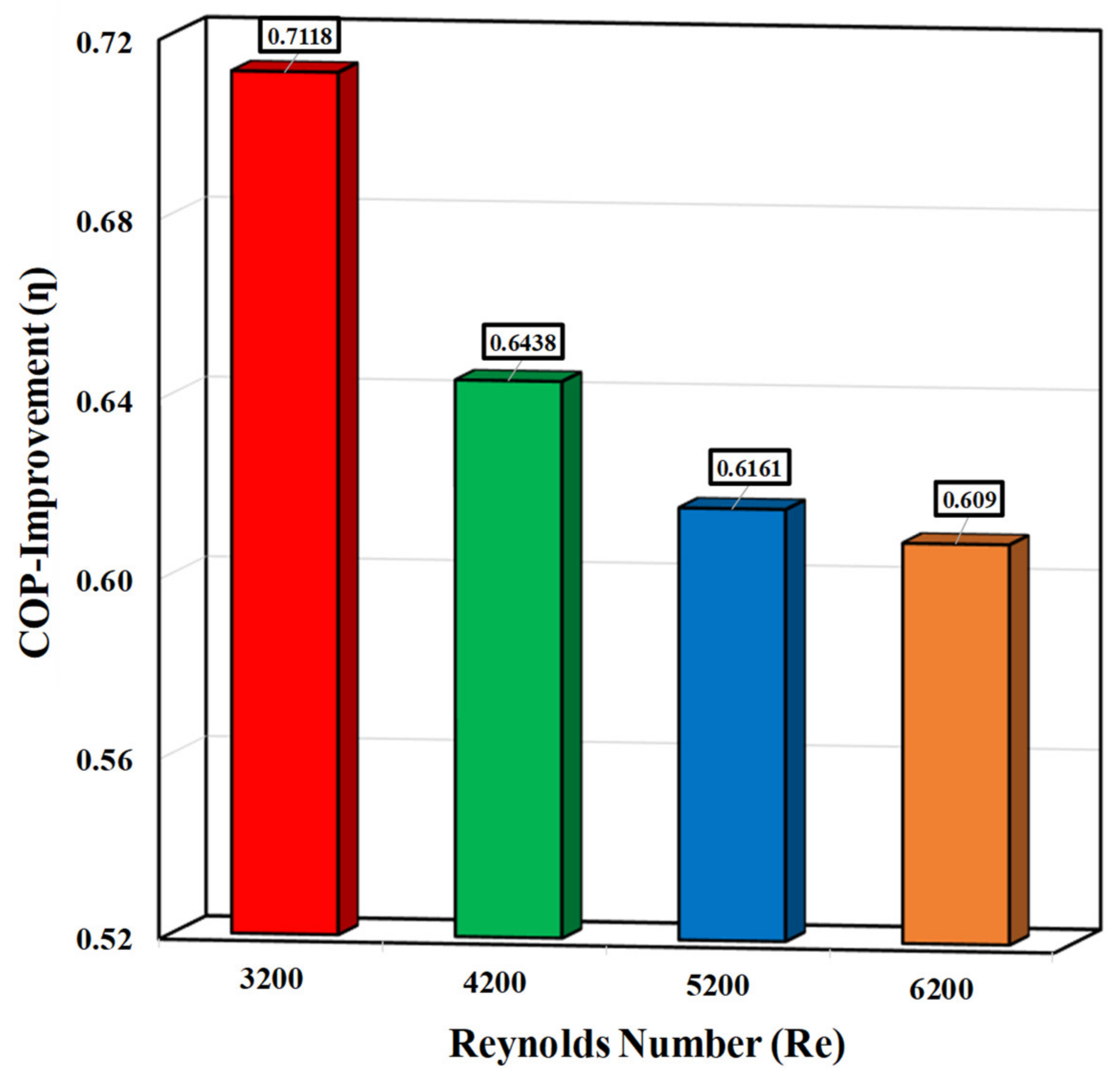
5.3. Impact of Reynolds Number of Hybrid Nanofluid

In the final section, the impact of the Reynolds number (Re) of hybrid nanofluids on the thermal performance of the BHE is investigated. Taking into account the balance between thermal resistance, pressure drop, and effectiveness, the Ag-MgO/water hybrid nanofluid at ϕ = 0.10 is selected as the best working fluid for further studies. Hence, in this research, the primary criterion for choosing the best hybrid nanofluid is the thermal enhancement called effectiveness (see Equation (12)). Four Reynolds numbers of the hybrid nanofluid, including 3200, 4200, 5200, and 6200, are chosen and evaluated. Also, similar to Section 5.1 and Section 5.2, Ag-MgO/water hybrid nanofluid (at ϕ = 0.10) with various Reynolds numbers is compared with the corresponding cases for pure water.
Figure 16 displays the outlet temperature variation with operating time using Ag-MgO/water hybrid nanofluid with different Reynolds numbers when ϕ = 0.10. Despite the minor differences between the various cases initially, all cases with Ag-MgO/water hybrid nanofluids at various Reynolds numbers have reached lower outlet temperatures than the cases of pure water at the corresponding Reynolds numbers. Furthermore, results demonstrate that the minimum outlet temperatures belong to the lowest Reynolds number (Re = 3200). By increasing the Reynolds number, the outlet temperature increases, as the more the fluid flow rate, the less time for heat transfer with the surrounding domain.
The effectiveness (E) for Ag-MgO/water hybrid nanofluid (ϕ = 0.10) with various Reynolds numbers is shown in Figure 17. It can be seen that Ag-MgO/water hybrid nanofluid at each value of Reynolds numbers is more effective than pure water. Also, an increase in the Reynolds number leads to a reduction in the effectiveness of both hybrid nanofluids and pure water. Moreover, Ag-MgO/water hybrid nanofluid’s effectiveness at Re = 3200, 4200, 5200, and 6200 are 37.02%, 36.25%, 36.15%, and 36.7%, respectively, compared with the corresponding cases of pure water.
The total thermal resistance of the borehole and the surrounding soil and the heat exchange rate per unit BHE depth for Ag-MgO/water hybrid nanofluid (ϕ = 0.10) and pure water with various Reynolds numbers are shown in Figure 18.
Figure 18 displays that Ag-MgO/water hybrid nanofluid (ϕ = 0.10) at each value of Reynolds number reaches a lower thermal resistance and a higher heat exchange rate than the cases of pure water. From the figure, the thermal resistances of Ag-MgO/water hybrid nanofluid at Re = 3200, 4200, 5200, and 6200 are lower than the corresponding cases of pure water by 1.14%, 0.88%, 0.82%, and 0.71%, respectively. Worth mentioning that augmentation in the Reynolds number leads to a reduction in the thermal resistance difference between the cases of hybrid nanofluid and pure water.
The pressure drop for Ag-MgO/water hybrid nanofluid (ϕ = 0.10) and pure water with various Reynolds numbers is presented in Figure 19. As a result, it can be concluded that employing Ag-MgO/water hybrid nanofluid at each Reynolds number instead of pure water causes higher rates of pressure drop, which can be explained by the Darcy–Weisbach equation. Moreover, the pressure drop of Ag-MgO/water hybrid nanofluid at Re = 3200, 4200, 5200, and 6200 is higher than in the corresponding cases for pure water by 37.97%, 38%, 38.02%, and 38.15%, respectively. Furthermore, as the Reynolds number increases from 3200 to 6200 (a growth of 93.75%), the pressure drop rises by 142.03% for pure water and 142.35% for the Ag-MgO/water hybrid nanofluid.
As explained earlier, the COP improvement factor includes both the ratios of friction factor (or pressure drop) and average Nusselt number so that higher COP improvement (more than unity; η > 1) indicates that the selected working fluid is efficient in terms of pressure drop and heat transfer. COP improvement using Ag-MgO/water hybrid nanofluid (ϕ = 0.10) with different Reynolds numbers is depicted in Figure 20. According to the figure, Ag-MgO/water hybrid nanofluid (ϕ = 0.10) at each value of Reynolds number has lower COP improvement than unity which means that studied cases are not economically viable because of having more pressure drop (or friction factor) than heat transfer improvement. Accordingly, it can be concluded that the COP improvement of the studied cases with various Reynolds numbers including Re = 3200, 4200, 5200, and 6200 is lower than pure water by 28.82%, 35.62%, 38.39%, and 39.1%, respectively. The maximum COP improvement is achieved by the case with Ag-MgO/water hybrid nanofluid (ϕ = 0.10) at Re = 3200. Figure 21 shows 2D contours of the temperature (top view at Z = 0) at different operating hours using Ag-MgO/water hybrid nanofluid at ϕ = 0.10 and Re = 3200. As time passes, the heat transfer from the working fluid to the other regions increases, leading to the better heat exchange of the BHE.
Using hybrid nanofluids instead of traditional fluids may decrease the size and cost of equipment required in the system. However, some types of hybrid nanofluids preparation techniques cost a lot. The hybrid nanofluids can be synthesized mainly by one-step or two-step methods. In the one-step process, the nanoparticles’ preparation and dispersion in the base fluid are parallel. The most important advantage of this technique is the reduction of the possibility of agglomeration of nanoparticles. However, it is difficult to cover it up for manufacturing purposes on a mass scale for the higher cost, which restricts the implementation of this method [36,58,59,60].
The two-step technique is initiated by preparing the nanoparticles and then dispersing them in an appropriate liquid. In this technique, nanoparticles’ high surface energy leads to aggregation and eventually sedimentation of nanoparticles which deteriorates hybrid nanofluid stability. The two-step approach is used for mass scale processing due to the effortlessness and relatively low cost. Among these two techniques, the two-step method is widely used by researchers and also industrialists [36,58,59,60].

6. Conclusions

A three-dimensional unsteady state numerical model of a single U-tube borehole heat exchanger was investigated by Ansys Fluent commercial software in this study. Four types of hybrid nanofluid, such as Ag-MgO/water, TiO2-Cu/water, Al2O3-CuO/water, and Fe3O4-MWCNT/water, were examined numerically to be used as working fluid in a single U-tube borehole heat exchanger. The selected hybrid nanofluid was evaluated at various values of volume fractions and Reynolds numbers.
After comparing the hybrid nanofluids at ϕ = 0.15 and Re = 3200, Ag-MgO/water hybrid nanofluid was chosen as the most favorable working fluid, considering its superior effectiveness, minor pressure drop, and appropriate thermal resistance amongst studied hybrid nanofluids compared to the pure water.
Hence, the effect of various volume fractions of Ag-MgO/water hybrid nanofluid at Re = 3200 was studied. All cases of Ag-MgO/water hybrid nanofluid with volume fractions of 0.05, 0.10, 0.15, and 0.20 have been able to achieve better effectiveness and lower thermal resistances than pure water except for the pressure drops, which were higher than pure water. Because of this balance between thermal resistance, pressure drop, and effectiveness, Ag-MgO/water hybrid nanofluid at ϕ = 0.10 is selected as the best working fluid for further studies.
Finally, the influence of different Reynolds numbers of Ag-MgO/water hybrid nanofluid with the volume fraction fixed at ϕ = 0.10 is analyzed. Ag-MgO/water hybrid nanofluids with Reynolds numbers of 3200, 4200, 5200, and 6200 showed greater effectiveness and lower thermal resistance than the corresponding cases of pure water, while their pressure drops were higher than pure water.
In summary, the effectiveness of a single U-tube borehole heat exchanger can be enhanced by 37.02% when applying the Ag-MgO/water hybrid nanofluid (at ϕ = 0.10 and Re = 3200) instead of the corresponding case of pure water. Also, the single U-tube borehole heat exchanger’s thermal resistance can be decreased by 1.14% when Ag-MgO/water hybrid nanofluid (at ϕ = 0.10 and Re = 3200) is used instead of the corresponding case of pure water as a heat carrier fluid. Therefore, based on a comparison made, it can be concluded that Ag-MgO/water hybrid nanofluid at a volume fraction of 0.10 and Reynolds number of 3200 is found to be the best working fluid in improving the thermal performance of the single U-tube borehole heat exchanger. Nevertheless, all the studied hybrid nanofluids show lower COP improvement than unity, indicating that using them as working fluid is not economically viable as they cause higher pressure drop than the heat transfer enhancement.
However, it is believed that further investigations such as conducting sensitivity analysis on the present numerical results and performing a numerical simulation of an actual model should be done as this is a new research line in the ground-source heat pump systems.

Author Contributions

Investigation, Software, Validation, Writing—original draft, H.J.; Funding acquisition, Supervision, Writing—review and editing, J.F.U.; Formal analysis, Methodology, Validation, Writing—review & editing, S.S.M.A.; Writing—review & editing, B.B. All authors have read and agreed to the published version of the manuscript.

Funding

This research work has been supported financially by the European project GEOCOND (funded by the European Union’s Horizon 2020 research and innovation program under grant agreement No 727583) and by the European project GEO4CIVHIC (funded by the European Union’s Horizon 2020 research and innovation program under grant agreement No 792355).

Data Availability Statement

Data available on request due to restrictions eg privacy or ethical.

Conflicts of Interest

The authors declare no conflict of interest.

Nomenclature

CpSpecific heat (J·kg−1·K−1)
EEffectiveness
g Gravitational acceleration (m·s−2)
HBorehole depth (m)
kThermal conductivity (W·m−1·K−1)
m ˙ Mass flow rate (kg·s−1)
NuNusselt number
dhHydraulic diameter (m)
QHeat exchange rate (W)
RThermal resistance (K·m·W−1)
hHeat transfer coefficient (W·m−2·K−1)
S Source term of momentum equation
τTime (s)
TTemperature (K)
V Velocity vector (m·s−1)
uVelocity (m·s−1)
lLength of the U-tube (m)
Greek Symbols
βThermal expansion coefficient (K−1)
ΔPPressure drop (Pa)
μDynamic viscosity (Pa·s)
ρDensity (kg·m−3)
ϕVolume fraction of nanoparticle
ηCoefficient of performance-improvement factor
fFriction factor
Subscripts
HNFHybrid nanofluid
NPNanoparticle
BFBase fluid
sSoil
aAverage
MAXMaximum
0Reference

Abbreviations

GSHPGround source heat pump
GHEGround heat exchanger
BHEBorehole heat exchanger
MWCNTMulti-wall carbon nanotube
COPCoefficient of performance

References

  1. Tsagarakis, K.P.; Efthymiou, L.; Michopoulos, A.; Mavragani, A.; Anđelković, A.S.; Antolini, F.; Bacic, M.; Bajare, D.; Baralis, M.; Bogusz, W.; et al. A review of the legal framework in shallow geothermal energy in selected European countries: Need for guidelines. Renew. Energy 2020, 147, 2556–2571. [Google Scholar] [CrossRef]
  2. Javadi, H.; Ajarostaghi, S.S.M.; Rosen, M.A.; Pourfallah, M. Performance of ground heat exchangers: A comprehensive review of recent advances. Energy 2019, 178, 207–233. [Google Scholar] [CrossRef]
  3. Philippe, M.; Bernier, M.; Marchio, D. Vertical geothermal borefields. Ashrae J. 2010, 52, 20–27. [Google Scholar]
  4. Fossa, M.; Rolando, D. Improving the Ashrae method for vertical geothermal borefield design. Energy Build. 2015, 93, 315–323. [Google Scholar] [CrossRef]
  5. Cullin, J.R.; Spitler, J.D.; Montagud, C.; Ruiz-Calvo, F.; Rees, S.J.; Naicker, S.S.; Konečný, P.; Southard, L.E. Validation of vertical ground heat exchanger design methodologies. Sci. Technol. Built Environ. 2015, 21, 137–149. [Google Scholar] [CrossRef]
  6. Rolando, D.; José, A.; Marco, F. A Web Application for Geothermal Borefield Design. In Proceedings of the World Geothermal Congress, Melbourne, Australia, 19–25 April 2015. [Google Scholar]
  7. Spitler, J.D.; Bernier, M. Vertical borehole ground heat exchanger design methods. In Advances in Ground-Source Heat Pump Systems; Woodhead Publishing: Cambridge, UK, 2016; pp. 29–61. [Google Scholar]
  8. Fossa, M.; Rolando, D. Improved Ashrae method for BHE field design at 10 year horizon. Energy Build. 2016, 116, 114–121. [Google Scholar] [CrossRef]
  9. Staiti, M.; Angelotti, A. Design of Borehole Heat Exchangers for Ground Source Heat Pumps: A Comparison between Two Methods. Energy Procedia 2015, 78, 1147–1152. [Google Scholar] [CrossRef] [Green Version]
  10. Fossa, M.; Davide, R.; Antonella, P. Investigation on the Effects of Different Time Resolutions in the Design and Simulation of BHE Fields. In Proceedings of the IGSHPA Technical/Research Conference and Expo, Denver, CO, USA, 14–16 March 2017. [Google Scholar]
  11. Capozza, A.; De Carli, M.; Zarrella, A. Design of borehole heat exchangers for ground-source heat pumps: A literature review, methodology comparison and analysis on the penalty temperature. Energy Build. 2012, 55, 369–379. [Google Scholar] [CrossRef]
  12. Fossa, M. Correct design of vertical borehole heat exchanger systems through the improvement of the ASHRAE method. Sci. Technol. Built Environ. 2017, 23, 1080–1089. [Google Scholar] [CrossRef]
  13. Ahmadfard, M.; Michel, B. Modifications to ASHRAE’s sizing method for vertical ground heat exchangers. Sci. Technol. Built Environ. 2018, 24, 803–817. [Google Scholar] [CrossRef]
  14. Fossa, M. The temperature penalty approach to the design of borehole heat exchangers for heat pump applications. Energy Build. 2011, 43, 1473–1479. [Google Scholar] [CrossRef]
  15. Badenes, B.; Burkhard, S.; Pla, M.Á.M.; Cuevas, J.M.; Bartoli, F.; Ciardelli, F.; González, R.M.; Ghafar, A.N.; Fontana, P.; Zuñiga, L.L.; et al. Development of advanced materials guided by numerical simulations to improve performance and cost-efficiency of borehole heat exchangers (BHEs). Energy 2020, 201, 117628. [Google Scholar] [CrossRef]
  16. Garbin, E.; Ludovico, M.; Eloisa, D.S.; Gilberto, A.; Javier, F.U.; Dimitris, M.; David, B.; Jacques, V.; Riccardo, P.; Adriana, B.; et al. Assessing Grouting Mix Thermo-Physical Properties for Shallow Geothermal Systems. In Proceedings of the 22nd EGU General Assembly Conference, Online. 4–8 May 2020. [Google Scholar]
  17. Javadi, H.; Ajarostaghi, S.S.M.; Rosen, M.A.; Pourfallah, M. A Comprehensive Review of Backfill Materials and Their Effects on Ground Heat Exchanger Performance. Sustainability 2018, 10, 4486. [Google Scholar] [CrossRef] [Green Version]
  18. Javadi, H.; Ajarostaghi, S.S.M.; Pourfallah, M.; Zaboli, M. Performance analysis of helical ground heat exchangers with different configurations. Appl. Therm. Eng. 2019, 154, 24–36. [Google Scholar] [CrossRef]
  19. Javadi, H.; Ajarostaghi, S.S.M.; Mousavi, S.S.; Pourfallah, M. Thermal analysis of a triple helix ground heat exchanger using numerical simulation and multiple linear regression. Geothermics 2019, 81, 53–73. [Google Scholar] [CrossRef]
  20. Javadi, H.; Urchueguia, J.F.; Ajarostaghi, S.S.M.; Badenes, B. Numerical Study on the Thermal Performance of a Single U-Tube Borehole Heat Exchanger Using Nano-Enhanced Phase Change Materials. Energies 2020, 13, 5156. [Google Scholar] [CrossRef]
  21. Bobbo, S.; Laura, C.; Antonella, B.; Stefano, R.; Laura, F. Characterization of Nanofluids Formed by Fumed Al2O3 in Water for Geothermal Applications. In Proceedings of the 16th International Refrigeration and Air Conditioning Conference, West Lafayette, IN, USA, 11–14 July 2016. [Google Scholar]
  22. Narei, H.; Ghasempour, R.; Noorollahi, Y. The effect of employing nanofluid on reducing the bore length of a vertical ground-source heat pump. Energy Convers. Manag. 2016, 123, 581–591. [Google Scholar] [CrossRef]
  23. Daneshipour, M.; Rafee, R. Nanofluids as the circuit fluids of the geothermal borehole heat exchangers. Int. Commun. Heat Mass Transf. 2017, 81, 34–41. [Google Scholar] [CrossRef]
  24. Sui, D.; Langåker, V.H.; Yu, Z. Investigation of thermophysical properties of Nanofluids for application in geothermal energy. Energy Procedia 2017, 105, 5055–5060. [Google Scholar] [CrossRef]
  25. Diglio, G.; Roselli, C.; Sasso, M.; Channabasappa, U.J. Borehole heat exchanger with nanofluids as heat carrier. Geothermics 2018, 72, 112–123. [Google Scholar] [CrossRef]
  26. Sun, X.-H.; Yan, H.; Massoudi, M.; Chen, Z.-H.; Wu, W.-T. Numerical Simulation of Nanofluid Suspensions in a Geothermal Heat Exchanger. Energies 2018, 11, 919. [Google Scholar] [CrossRef] [Green Version]
  27. Peng, Y.; Yong, W.; Ruiqing, D. The Effect of Nanofluid to Vertical Single U-Tube Ground Heat Exchanger. In Proceedings of the 4th Building Simulation and Optimization Conference, Cambridge, UK, 11–12 September 2018. [Google Scholar]
  28. Mishra, S.; Sikata, S.; Das, D.K. Theoretical analysis on application of nanofluids in ground source heat pumps for building cooling. Int. J. Recent Technol. Mech. Electr. Eng. 2018, 5, 28–37. [Google Scholar]
  29. Du, R.; Jiang, D.; Wang, Y.; Shah, K.W. An experimental investigation of CuO/water nanofluid heat transfer in geothermal heat exchanger. Energy Build. 2020, 227, 110402. [Google Scholar] [CrossRef]
  30. Du, R.; Jiang, D.; Wang, Y. Numerical Investigation of the Effect of Nanoparticle Diameter and Sphericity on the Thermal Performance of Geothermal Heat Exchanger Using Nanofluid as Heat Transfer Fluid. Energies 2020, 13, 1653. [Google Scholar] [CrossRef] [Green Version]
  31. Sarkar, J.; Ghosh, P.; Adil, A. A review on hybrid nanofluids: Recent research, development and applications. Renew. Sustain. Energy Rev. 2015, 43, 164–177. [Google Scholar] [CrossRef]
  32. Leong, K.; Ahmad, K.K.; Ong, H.C.; Ghazali, M.; Baharum, A. Synthesis and thermal conductivity characteristic of hybrid nanofluids-A review. Renew. Sustain. Energy Rev. 2017, 75, 868–878. [Google Scholar] [CrossRef]
  33. Hamzah, M.H.; Sidik, N.A.C.; Ken, T.L.; Mamat, R.; Najafi, G. Factors affecting the performance of hybrid nanofluids: A comprehensive review. Int. J. Heat Mass Transf. 2017, 115, 630–646. [Google Scholar] [CrossRef]
  34. Minea, A.A. Challenges in hybrid nanofluids behavior in turbulent flow: Recent research and numerical comparison. Renew. Sustain. Energy Rev. 2017, 71, 426–434. [Google Scholar] [CrossRef]
  35. Gupta, M.; Singh, V.; Kumar, S.; Kumar, S.; Dilbaghi, N.; Said, Z. Up to date review on the synthesis and thermophysical properties of hybrid nanofluids. J. Clean. Prod. 2018, 190, 169–192. [Google Scholar] [CrossRef]
  36. Sajid, M.U.; Hafiz, M.A. Thermal conductivity of hybrid nanofluids: A critical review. Int. J. Heat Mass Transf. 2018, 126, 211–234. [Google Scholar] [CrossRef]
  37. Kumar, D.D.; Arasu, A.V. A comprehensive review of preparation, characterization, properties and stability of hybrid nanofluids. Renew. Sustain. Energy Rev. 2018, 81, 1669–1689. [Google Scholar] [CrossRef]
  38. Suresh, S.; Venkitaraj, K.P.; Selvakumar, P.; Chandrasekar, M. Effect of Al2O3–Cu/water hybrid nanofluid in heat transfer. Exp. Therm. Fluid Sci. 2012, 38, 54–60. [Google Scholar] [CrossRef]
  39. Labib, M.N.; Nine, J.; Afrianto, H.; Chung, H.; Jeong, H. Numerical investigation on effect of base fluids and hybrid nanofluid in forced convective heat transfer. Int. J. Therm. Sci. 2013, 71, 163–171. [Google Scholar] [CrossRef]
  40. Takabi, B.; Salehi, S. Augmentation of the Heat Transfer Performance of a Sinusoidal Corrugated Enclosure by Employing Hybrid Nanofluid. Adv. Mech. Eng. 2014, 6, 147059. [Google Scholar] [CrossRef]
  41. Sundar, L.S.; Singh, M.K.; Sousa, A.C. Enhanced heat transfer and friction factor of MWCNT–Fe3O4/water hybrid nanofluids. Int. Commun. Heat Mass Transf. 2014, 52, 73–83. [Google Scholar] [CrossRef]
  42. Madhesh, D.; Parameshwaran, R.; Kalaiselvam, S. Experimental investigation on convective heat transfer and rheological characteristics of Cu–TiO2 hybrid nanofluids. Exp. Therm. Fluid Sci. 2014, 52, 104–115. [Google Scholar] [CrossRef]
  43. Yarmand, H.; Gharehkhani, S.; Ahmadi, G.; Shirazi, S.F.S.; Baradaran, S.; Montazer, E.; Zubir, M.N.M.; Alehashem, M.S.; Kazi, S.; Dahari, M. Graphene nanoplatelets–Silver hybrid nanofluids for enhanced heat transfer. Energy Convers. Manag. 2015, 100, 419–428. [Google Scholar] [CrossRef]
  44. Esfe, M.H.; Arani, A.A.A.; Rezaie, M.; Yan, W.M.; Karimipour, A. Experimental determination of thermal conductivity and dynamic viscosity of Ag–MgO/water hybrid nanofluid. Int. Commun. Heat Mass Transf. 2015, 66, 189–195. [Google Scholar] [CrossRef]
  45. Toghraie, D.; Chaharsoghi, V.A.; Afrand, M. Measurement of thermal conductivity of ZnO–TiO2/EG hybrid nanofluid. J. Therm. Anal. Calorim. 2016, 125, 527–535. [Google Scholar] [CrossRef]
  46. Van Trinh, P.; Anh, N.N.; Thang, B.H.; Hong, N.T.; Hong, N.M.; Khoi, P.H.; Minh, P.N.; Hong, P.N. Enhanced thermal conductivity of nanofluid-based ethylene glycol containing Cu nanoparticles decorated on a Gr–MWCNT hybrid material. R. Soc. Chem. Adv. 2017, 6, 318–326. [Google Scholar] [CrossRef] [Green Version]
  47. Sundar, L.S.; Singh, M.K.; Ferro, M.; Sousa, A.C. Experimental investigation of the thermal transport properties of graphene oxide/Co3O4 hybrid nanofluids. Int. Commun. Heat Mass Transf. 2017, 84, 1–10. [Google Scholar] [CrossRef]
  48. Sahoo, R.R.; Sarkar, J. Heat transfer performance characteristics of hybrid nanofluids as coolant in louvered fin automotive radiator. Heat Mass Transf. 2016, 53, 1923–1931. [Google Scholar] [CrossRef]
  49. Ajarostaghi, S.S.M.; Zaboli, M.; Nourbakhsh, M. Numerical evaluation of turbulence heat transfer and fluid flow of hybrid nanofluids in a pipe with innovative vortex generator. J. Therm. Anal. Calorim. 2020, 143, 1–15. [Google Scholar]
  50. Karouei, S.H.H.; Ajarostaghi, S.S.M.; Gorji-Bandpy, M.; Fard, S.R.H. Laminar heat transfer and fluid flow of two various hybrid nanofluids in a helical double-pipe heat exchanger equipped with an innovative curved conical turbulator. J. Therm. Anal. Calorim. 2021, 143, 1455–1466. [Google Scholar] [CrossRef]
  51. Ajarostaghi, S.S.M.; Shirzad, M.; Rashidi, S.; Li, L.K.B. Heat transfer performance of a nanofluid-filled tube with wall corrugations and center-cleared twisted-tape inserts energy sources, part A recover. Energy Sources Part A Recover. Util. Environ. Eff. 2020, 1–21. [Google Scholar] [CrossRef]
  52. Hamedani, F.A.; Ajarostaghi, S.S.M.; Hosseini, S.A. Numerical evaluation of the effect of geometrical and operational parameters on thermal performance of nanofluid flow in convergent–divergent tube. J. Therm. Anal. Calorim. 2020, 140, 1483–1505. [Google Scholar] [CrossRef]
  53. Noorbakhsh, M.; Ajarostaghi, S.S.M.; Zaboli, M.; Kiani, B. Thermal analysis of nanofluids flow in a double pipe heat exchanger with twisted tapes insert in both sides. J. Therm. Anal. Calorim. 2021, 1–12. [Google Scholar] [CrossRef]
  54. Khodadadi, J.M.; Fan, L. Expedited freezing of nanoparticle-enhanced phase change materials (NEPCM) exhibited through a simple 1-D stefan problem formulation. In Proceedings of the Heat Transfer Summer Conference, San Francisco, CA, USA, 19–23 July 2009. [Google Scholar]
  55. Hassan, M.; Marin, M.; Ellahi, R.; Alamri, S.Z. Exploration of convective heat transfer and flow characteristics synthesis by Cu–Ag/water hybrid-nanofluids. Heat Transf. Res. 2018, 49, 1837–1848. [Google Scholar] [CrossRef]
  56. Jalaluddin, J.; Miyara, A. Thermal performance and pressure drop of spiral-tube ground heat exchangers for ground-source heat pump. Appl. Therm. Eng. 2015, 90, 630–637. [Google Scholar] [CrossRef]
  57. Jalaluddin, J.; Miyara, A.; Tsubaki, K.; Inoue, S.; Yoshida, K. Experimental study of several types of ground heat exchanger using a steel pile foundation. Renew. Energy 2011, 36, 764–771. [Google Scholar] [CrossRef]
  58. Kadirgama, K.; Anamalai, K.; Ramachandran, K.; Ramasamy, D.; Samykano, M.; Kottasamy, A.; Rahman, M.M. Thermal analysis of SUS 304 stainless steel using ethylene glycol/nanocellulose-based nanofluid coolant. Int. J. Adv. Manuf. Technol. 2018, 97, 2061–2076. [Google Scholar] [CrossRef]
  59. Safiei, W.; Rahman, M.M.; Yusoff, A.R.; Radin, M.R. Preparation, stability and wettability of nanofluid: A review. J. Mech. Eng. Sci. 2020, 14, 7244–7257. [Google Scholar] [CrossRef]
  60. Urmi, W.T.; Shafiqah, A.; Rahman, M.; Kadirgama, K.; Maleque, A. Preparation Methods and Challenges of Hybrid Nanofluids: A Review. J. Adv. Res. Fluid Mech. Therm. Sci. 2020, 78, 56–66. [Google Scholar] [CrossRef]
Figure 1. Schematic of the borehole heat exchanger (BHE): (a) 3D view, and (b) 2D view (ground surface).
Energies 14 02892 g001aEnergies 14 02892 g001b
Figure 2. Generated grid for the BHE and the grid independence test: (a) 3D view, (b) 2D view, and (c) the grid independence test.
Energies 14 02892 g002aEnergies 14 02892 g002b
Figure 3. Verification of this numerical study with the experimental data.
Energies 14 02892 g003
Figure 4. The variation of the outlet temperature with operating time using various hybrid nanofluids at ϕ = 0.15 and Re = 3200.
Energies 14 02892 g004
Figure 5. Effectiveness for various hybrid nanofluids at ϕ = 0.15 and Re = 3200.
Energies 14 02892 g005
Figure 6. The total thermal resistance of the borehole and the surrounding soil and the heat exchange rate per unit BHE depth for various hybrid nanofluids at ϕ = 0.15 and Re = 3200.
Energies 14 02892 g006
Figure 7. Pressure drop for various hybrid nanofluids at ϕ = 0.15 and Re = 3200.
Energies 14 02892 g007
Figure 8. Coefficient of performance (COP)-improvement for various hybrid nanofluids at ϕ = 0.15 and Re = 3200.
Energies 14 02892 g008
Figure 9. Two-dimensional (2D) contours of the temperature distribution of the BHE at various hours of operating using Ag-MgO/water hybrid nanofluid when ϕ = 0.15 and Re = 3200 (Top view at Z = 0).
Energies 14 02892 g009
Figure 10. The variation of the outlet temperature with operating time using Ag-MgO/water hybrid nanofluid with different volume fractions at Re = 3200.
Energies 14 02892 g010
Figure 11. Effectiveness when using Ag-MgO/water hybrid nanofluid with different volume fractions at Re = 3200.
Energies 14 02892 g011
Figure 12. The total thermal resistance of the borehole and the surrounding soil and the heat exchange rate per unit BHE depth for Ag-MgO/water hybrid nanofluid with different volume fractions at Re = 3200.
Energies 14 02892 g012
Figure 13. Pressure drop when using Ag-MgO/water hybrid nanofluid with different volume fractions at Re = 3200.
Energies 14 02892 g013
Figure 14. COP improvement of Ag–MgO/water hybrid nanofluid with different volume fractions at Re = 3200.
Energies 14 02892 g014
Figure 15. Two-dimensional (2D) contours of the temperature distribution of the BHE at various hours of operating using Ag-MgO/water hybrid nanofluid at ϕ = 0.10 and Re = 3200 (Top view at Z = 0).
Energies 14 02892 g015
Figure 16. The variation of the outlet temperature with operating time using Ag-MgO/water hybrid nanofluid with different Reynolds numbers at ϕ = 0.10.
Energies 14 02892 g016
Figure 17. Effectiveness when using Ag-MgO/water hybrid nanofluid with different Reynolds numbers at ϕ = 0.10.
Energies 14 02892 g017
Figure 18. The total thermal resistance of the borehole and the surrounding soil and the heat exchange rate per unit BHE depth for Ag-MgO/water hybrid nanofluid with different Reynolds numbers at ϕ = 0.10.
Energies 14 02892 g018
Figure 19. Pressure drop when using Ag-MgO/Water hybrid nanofluid with different Reynolds numbers at ϕ = 0.10.
Energies 14 02892 g019
Figure 20. COP improvement when using Ag-MgO/water hybrid nanofluid with different Reynolds numbers at ϕ = 0.10.
Energies 14 02892 g020
Figure 21. Two-dimensional (2D) contours of the temperature distribution of the BHE at various hours of operating using Ag–MgO/water hybrid nanofluid at Re = 3200 and ϕ = 0.10 (Top view at Z = 0).
Energies 14 02892 g021
Table 1. Geometric and operating parameters and studied variables.
ParametersValue
Soil Diameter, D52 m
Casing Outer Diameter, D40.1398 m
Casing Inner Diameter, D30.1298 m
U-tube Outer Diameter, D20.033 m
U-tube Inner Diameter, D10.026 m
Clay Length, L11.5 m
Sandy-Clay Length, L21.5 m
Borehole Depth, H2 m
U-tube Length2 m
Leg Spacing of U-tube, X0.02 m
Inlet Temperature300.15 K
Operating Duration24 h
Operating ModeCooling
Hybrid NanofluidsAg-MgO (50:50 vol.%)/Water
TiO2-Cu (50:50 vol.%)/Water
Al2O3-CuO (50:50 vol.%)/Water
Fe3O4-MWCNT (50:50 vol.%)/Water
Volume Fractions of Nanoparticles0.05, 0.10, 0.15, 0.20
Reynolds Numbers3200, 4200, 5200, 6200
Table 2. Thermo-physical properties of U-tube, casing, backfill, and soil [18]. (Reprinted from Javadi, Hossein, Seyed Soheil Mousavi Ajarostaghi, Mohsen Pourfallah, and Mohammad Zaboli. “Performance analysis of helical ground heat exchangers with different configurations.” Applied Thermal Engineering 154 (2019): 24–36. Copyright (2019), with permission from Elsevier).
ParametersValue
Polyethylene (PE)
Density (kg/m3)920
Specific Heat Capacity (J/kg·K)2300
Thermal Conductivity (W/m·K)0.35
Steel
Density (kg/m3)8030
Specific Heat Capacity (J/kg·K)502.48
Thermal Conductivity (W/m·K)16.27
Silica Sand
Density (kg/m3)2210
Specific Heat Capacity (J/kg·K)750
Thermal Conductivity (W/m·K)1.4
Clay
Density (kg/m3)1700
Specific Heat Capacity (J/kg·K)1800
Thermal Conductivity (W/m·K)1.2
Sandy-Clay
Density (kg/m3)1960
Specific Heat Capacity (J/kg·K)1200
Thermal Conductivity (W/m·K)2.1
Table 3. Thermo-physical properties of base fluid and nanoparticles.
PropertyBase FluidNanoparticles
WaterCu [54]CuO [54]Al2O3 [54]TiO2 [54]Fe3O4 [41]MWCNT [41]Ag [44]MgO [44]
Density
(kg/m3)
998.289336510388041755180160010,5003580
Specific Heat Capacity (J/kg·K)4182385540792692670796235874
Thermal Conductivity (W/m·K)0.64011842.348.49.7300042955
Viscosity
(Pa·s)
0.001003--------
Table 4. Thermo-physical properties of various hybrid nanofluids at ϕ = 0.15.
PropertyHybrid Nanofluids
Ag-MgO
(50:50 vol.%)/Water
TiO2-Cu (50:50 vol.%)/WaterAl2O3-CuO (50:50 vol.%)/WaterFe3O4-MWCNT (50:50 vol.%)/Water
Density (kg/m3)2810.742664.942257.241715.74
Specific Heat Capacity (J/kg·K)1338.29301452.70671732.37432117.8970
Thermal Conductivity (W/m·K)2.27692.27532.21832.2842
Viscosity (Pa·s)0.00240.00240.00240.0024
Table 5. Thermo-physical properties of Ag-MgO (50:50 vol.%)/Water hybrid nanofluid at various volume fractions.
PropertyVolume Fractions
ϕ = 0.05ϕ = 0.10ϕ = 0.15ϕ = 0.20
Density (kg/m3)1602.382206.562810.743414.92
Specific Heat Capacity (J/kg·K)2519.28141767.10351338.29301061.2159
Thermal Conductivity (W/m·K)1.33131.74522.27692.9852
Viscosity (Pa·s)0.00130.00170.00240.0035
Publisher’s Note: MDPI stays neutral with regard to jurisdictional claims in published maps and institutional affiliations.

