Article

Design of a Tandem Compressor for the Electrically-Driven Turbocharger of a Hybrid City Car †

1
Department of Mechanical and Aerospace Engineering, University of Roma Sapienza, 00185 Rome, Italy
2
Department of Industrial and Civil Engineering, Niccolò Cusano University, 00166 Rome, Italy
*
Author to whom correspondence should be addressed.
Presented at the First World Energies Forum, 14 September–5 October 2020; Available online: https://wef.sciforum.net/. Published: 12 September 2020.
Energies 2021, 14(10), 2890; https://doi.org/10.3390/en14102890
Submission received: 10 April 2021 / Revised: 29 April 2021 / Accepted: 10 May 2021 / Published: 17 May 2021
(This article belongs to the Special Issue Selected Papers from The First World Energies Forum (WEF-1))

Abstract

:
Within a broader national project aimed at the hybridization of a standard city car (the 998 cc Mitsubishi-derived gasoline engine of the Smart W451), our team tackled the problem of improving the supercharger performance and response. The originally conceived design innovation was that of eliminating the mechanical connection between the compressor and the turbine. In the course of the study, it turned out that it is also possible to modify both components to extract extra power from the engine and to use it to recharge the battery pack. This required a redesign of both compressor and turbine. First, the initial configuration was analyzed on the basis of the design data provided by the manufacturer. Then, a preliminary performance assessment of the turbocharged engine allowed us to identify three “typical” operating points that could be used to properly redesign the turbomachinery. It was decided to maintain the radial configuration for both turbine and compressor, but to redesign the latter by adding an inducer. For the turbine, only minor modifications to the nozzle guide vanes (NGV) and rotor blades shape were deemed necessary, while a more substantial modification was in order for the compressor. Fully 3-D computational fluid dynamics simulations of the rotating machines were performed to assess their performance at three operating points: the kick-in point of the original turbo (2000 rpm), the maximum power regime (5500 rpm), and an intermediate point (3500 rpm) close to the minimum specific fuel consumption for the original engine. The results presented in this paper demonstrate that the efficiency of the compressor is noticeably improved for steady operation at all three operating points, and that its choking characteristics have been improved, while its surge line has not been appreciably affected. The net energy recovery was also calculated and demonstrated interesting returns in terms of storable energy in the battery pack.

1. Introduction

The increasing concern about CO2 emissions led to stricter regulations on the exhaust limitation of internal combustion engines (ICE). With specific reference to gasoline-fueled ICE, the automotive industry response has been articulated in three directions (listed here in order of decreasing “perceived emission levels”): the downsizing of existing engine [1,2], the introduction of hybrid propulsion systems [3], and the design of all-electric vehicles. The three solutions are not equivalent in terms of feasibility, cost, and time-to-market, and only the first one is based on a sufficiently mature technology to be immediately implemented without substantial modifications to the production and assembly lines. Within this scenario, the Italian Ministry of Research launched a series of R&D projects aimed at a better definition of short-term modifications to existing gasoline ICE.
Since downsized engines are not palatable for the average European customer, it is necessary to increase the power density of the ICE: turbocharging is an industrially mature measure introduced in large-series commercial power units already in the 1970s [4]. It has been continuously improved -first by testing it on racing prototypes and “Gran Turismo” competition cars and then by its limited introduction into the high-end, high-performance luxury sports car niche—until the advance in electronic control units made its adoption possible on large series commercial vehicles.
In gasoline-fueled ICE, most turbocharger units today are back-to-back, radial/radial compressor/turbine assemblies (Figure 1 Standard Turbocharger assembly): the exhaust gases from the ICE power the turbine that in turn drives the compressor. A schematic representation of the process and of the subsumed ideal and real (indicated) cycle [5] are shown in Figure 2. Even neglecting the unavoidable flow fluctuations intrinsic in reciprocating pistons engines, “normal” engine operating curves are not stationary but periodically changing in time, so that the mass flowrate of both the intake air (point 1 in Figure 2) processed by the compressor and that at engine exhaust/turbine entry (point 2 in the same figure) vary continuously, as well as the exhaust temperature and pressure (and, strictly speaking, also the exhaust gas composition). Since the operating curves of the two components have substantially different characteristics (Figure 3 and Figure 4), in modern turbocharged engines a dedicated Electronic Control Unit (ECU) ensures a proper matching either by limiting the mass flowrate through the turbine via the controlled venting of a portion of the exhaust gases directly into the discharge plenum through a valve called “waste gate”, or by modifying the stagger of the turbine NGV, or both.
The most popular configuration today consists of a small and fast radial compressor with fixed radial blades and a non-vaned diffuser and of a radial turbine with fixed NGV: only few units are equipped with variable geometry NGV, which improve both the efficiency and the stability of the unit at all regimes.
The results of a previous study [6] demonstrated that removing the direct mechanical coupling between turbine and compressor (having the former feed the vehicle battery via an inverter and the latter powered by an electrical motor feeding on the battery) provides non-negligible fuel savings (of the order of 5 to 6%) under realistic operating conditions. To enhance the efficiency of the unit, an optimization of the compressor impeller was performed in this study [7] and is discussed here. The trends indicated by recent published research, suggest three main design modifications: (a) introduction of a hub-case vortex generator, (b) implementation of boundary layer suction/blowing systems, and (c) addition of a tandem blade [8,9]. All published studies [10,11] refer to large-scale compressors, and given the small size of the unit under study here, the last solution is particularly attractive because its implementation is relatively simple and does not imply additional external systems.
In a “tandem centrifugal rotor”, the incoming air flows first through a specifically designed axial rotor, the “inducer”, before entering the radial portion of the blade: this arrangement creates a gap between the two cascades whose geometry strongly influences the flow field [12,13,14]. The gap is generally described by the circumferential relative position of the cascades, called clock, and by their axial distance, called displacement (Figure 5).
It ought to be remarked that the definition “tandem blading” has been used in the past to describe a slotted/slanted pairing of two blades or half-blades in an axial compressor [15]. Though some of these “axial-tandem” configurations reached the commercial stage [8], the concept, structure, and complication of the “tandem centrifugal” compressors is quite different and much more promising. For one thing, this very peculiar arrangement is still object of often contradictory studies. The interest in this type of impeller starts around 1940, but the first detailed study was carried out from Boyce and Nishida [12] in 1977. On the basis of a series of experiments they concluded that the efficiency of a centrifugal compressor could be improved by introducing a 33% clock inducer blade that reduces the chance of boundary layer separation on the splitter blades. In 1993, Hoffman and Kadner [13] tested multiple clock combinations in an adjustable impeller, with fixed axial displacement. The inducer blade was optimized for the design inflow, but nevertheless all tested compressors performed worse than the baseline one. Their results demonstrate though the great influence of the clock on the performance and consistently proved that the 0% (reference position) was the best performing one among the tested tandem arrangements. A 2002 Pratt and Whitney report [14] presented the results of experimental tests on an aircraft centrifugal compressor modified into a tandem impeller by making a radial slot in the main blade: here, too, the performance was never at par with that of the baseline, but the 0% clock was confirmed as the best performer, due to the interruption in the boundary layer growth brought about by the free space between the two rotors. It was remarked that the flow field presented an enhanced uniformity that might increase the efficiency of a diffuser, although this part was not included in the study. A similar study [16] led to the same results. Michelassi et al. [17] followed a different approach, designing an inducer as a slot of the main blade but keeping the splitter blade unchanged, and introduced the blade overlapping as an additional optimization parameter. Their study demonstrates that both the efficiency and the total pressure ratio were increased, but more importantly, that the impeller showed improved off-design performance and that the outflow characteristics were also better suited for vaned diffusers. In 2016, Hanus et al. [18,19] showed that there is an “optimal” compression ratio of the inducer namely β = 1.2, that results in an overall better performance of the tandem compressor. Following this path, two other studies [20,21] demonstrated that a careful and specific design of the axial inducer blades improved performance and extends the operative range. Despite the often controversial results which characterize this clearly not-yet-mature technology, the undisputable evidence is that the inducer design is crucial for the performance of the machine. This means that its design ought to be “optimal” per se, without compromises due to its subsequent “coupling” with its radial appendix. A second issue is that the performance derangements are strictly related to viscous phenomena and Mach losses [14,17], and this demonstrates on one side the strong case-dependent nature of the tandem design and on the other suggests that a careful optimization must be performed before finalizing such a configuration.
The aim of this investigation was to develop an inducer-bladed (Tandem) version of a compressor starting from a conventional Garrett GT12, in order to explore the possible performance improvements. Given the increasing industrial interest in engine downsizing, a secondary goal was to investigate the feasibility of this “revamping” to small size turbochargers. In the following, the inducer is treated as an axial compressor cascade and its basic design is developed with the standard two-dimensional turbomachinery theory. Both geometries (conventional and tandem) are then investigated by a series of CFD simulations performed with a commercial software (ANSYS-CFX). Since it is known that the two parameters that most influence performance are the inducer/exducer axial displacement and clock (see Figure 5), the tandem impeller geometry has undergone a Design of Experiment (DOE) campaign in order to optimize both performance and range. The final “optimal” compressor maps are reported, and the ensuing flow fields are analyzed as of their respective entropy generation maps to gain a better insight of the boundary layer interaction between inducer and exducer. As mentioned above, the analysis was performed on three operative points representatives of the real operation of the hybrid turbocharger.
Both the design of the compressor, discussed here in detail, and that of the turbine, subject of a related study [22], have been finalized on the basis of an initial system performance study (engine + turbocharger + auxiliaries, [6]), and the components will be built and assembled on the original ICE for bench testing. To present the compressor data the corrected massflow rate is computed as follows:
m r = m R · T 0 P 0 k D 0 2
However some massflow rate values will be expressed in Imperial units to be more easily compared to the Garret official compressor Map, which is expressed in these units.

2. The Original Turbocharged Engine

The engine for which the new turbocharger is being designed is the three cylinder, 998cc gasoline engine W451, originally produced by Mitsubishi and modified by Mercedes for the Smart ForTwo. In this very compact packaging (Figure 6), the turbocharger unit is mounted in a standard fashion, with no intercooling and with a direct mechanical coupling between the two rotors (i.e., they rotate at the same speed and a compromise has been struck between the optimal map of the turbine and that of the compressor, so that neither machine is operating on its optimal curve).

3. Rationale of the Proposed Modifications

At system level, the existing configuration can be improved by adopting what is known as “hybrid turbo compound” (Figure 7): the mechanical link between compressor and turbine is eliminated and each machine operates along its “optimal” curve. The compressor is powered by an electrical motor fed by the on-board battery pack, and the turbine is coupled to an electrical generator that feeds the same battery pack. In this way, the excess power can be directly recovered by storing it in the form of electrical potential: this solution is particularly advantageous in a hybrid propulsion system in which additional kinetic-to-electrical energy recovery is enforced via a KERS. The installation of a custom Electrical Control Unit, together with a specific engine tuning, results in the elimination of the waste gate valve, thus increasing propulsion efficiency under road conditions. As a direct consequence of the mechanical separation of the two rotors and given the reduced compression ratio required by the ICE, the compressor rotational velocity is lower than that of the turbine at each engine operating point, and a further geometric optimization may result in substantial savings in fuel economy (less energy extracted from the battery per unit of energy delivered to the wheels).

4. The Modified Radial Compressor: Geometry and Computational Mesh

4.1. The Original GT12 Compressor Geometry

To validate our results, a CFD simulation was performed on the original GT12 compressor geometry, shown in Figure 8. The basic ANSYS package offers several ways to generate a 3-D solid model and mesh it, and the steps adopted in the construction are outlined here below.
Since the original drawings are proprietary, images and physical samples of rotors were carefully examined to extract representative quantitative information (diameters, angles, curvatures, blade thickness, etc.) sufficient to generate a proper geometrical model;
  • The obtained geometries were digitalized.
  • The virtual design was adjusted for the CFD simulations: first, the domain occupied by the actual rotor was lengthened by 1.5 diameters of the inlet eye (30 mm) on the intake side, to allow for a numerical “smoothing” of the flow quantities from the inlet boundary condition to the blade leading edge. The outlet was lengthened by 10% of the blade tip diameter (2 mm) to account for the rotor/diffuser clearance.
  • The blade profile was generated as a cubic spline. The incidence β (angle between the relative velocity vector and the blade tangent at leading edge) was specified from the geometrical drawing, and a blade overlap of θ = 60° was imposed. The splitter was set to begin at mid channel length. Blade maximum thickness was set to 1.3% of the chord of the blade and clearance to 2% of the blade span.
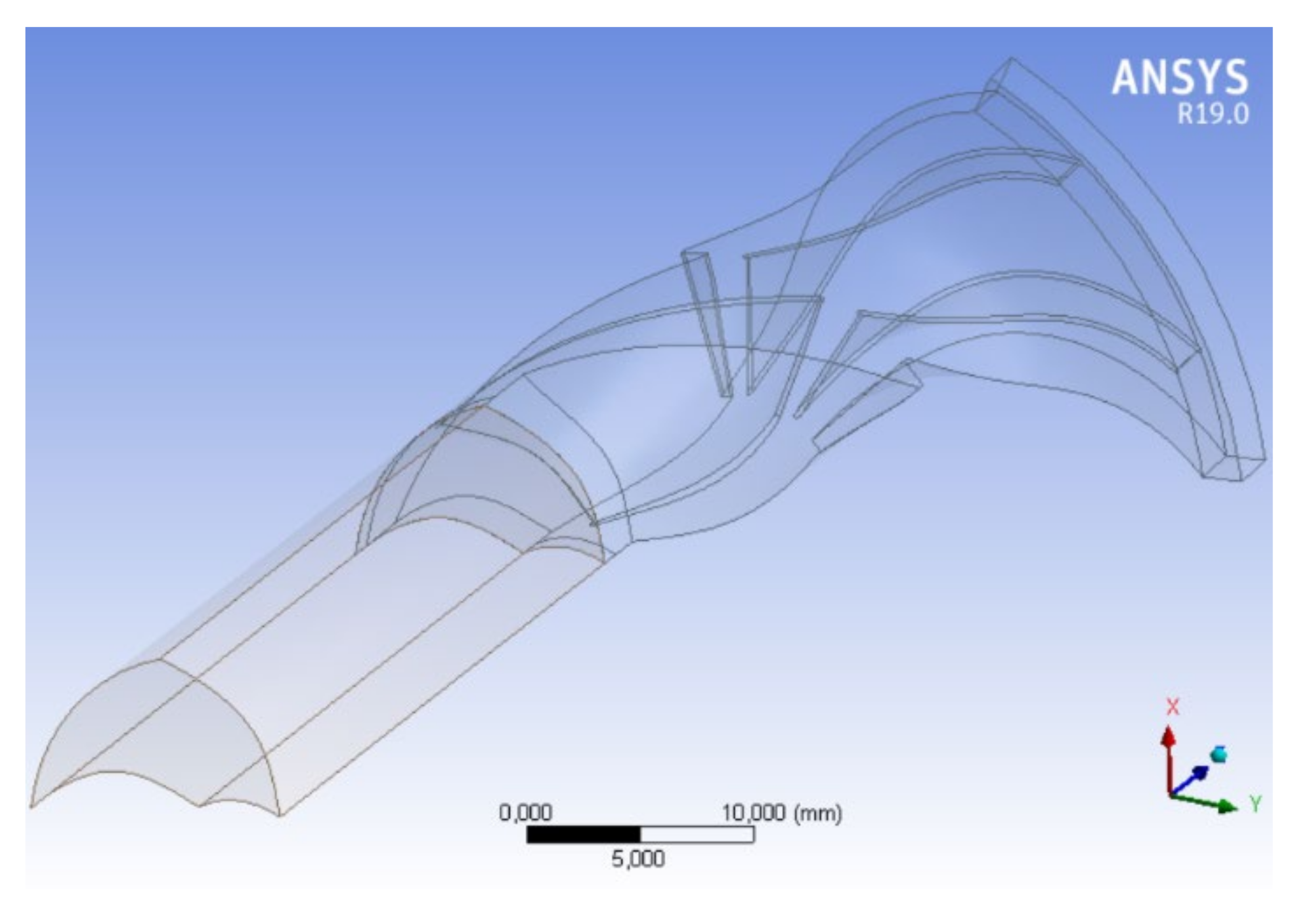
  • The computational domain consists in a 60° solid slice of the impeller and includes one main and one splitter blade. This configuration take advantage of the axisymmetric nature of the impeller, to save computational time (Figure 9).
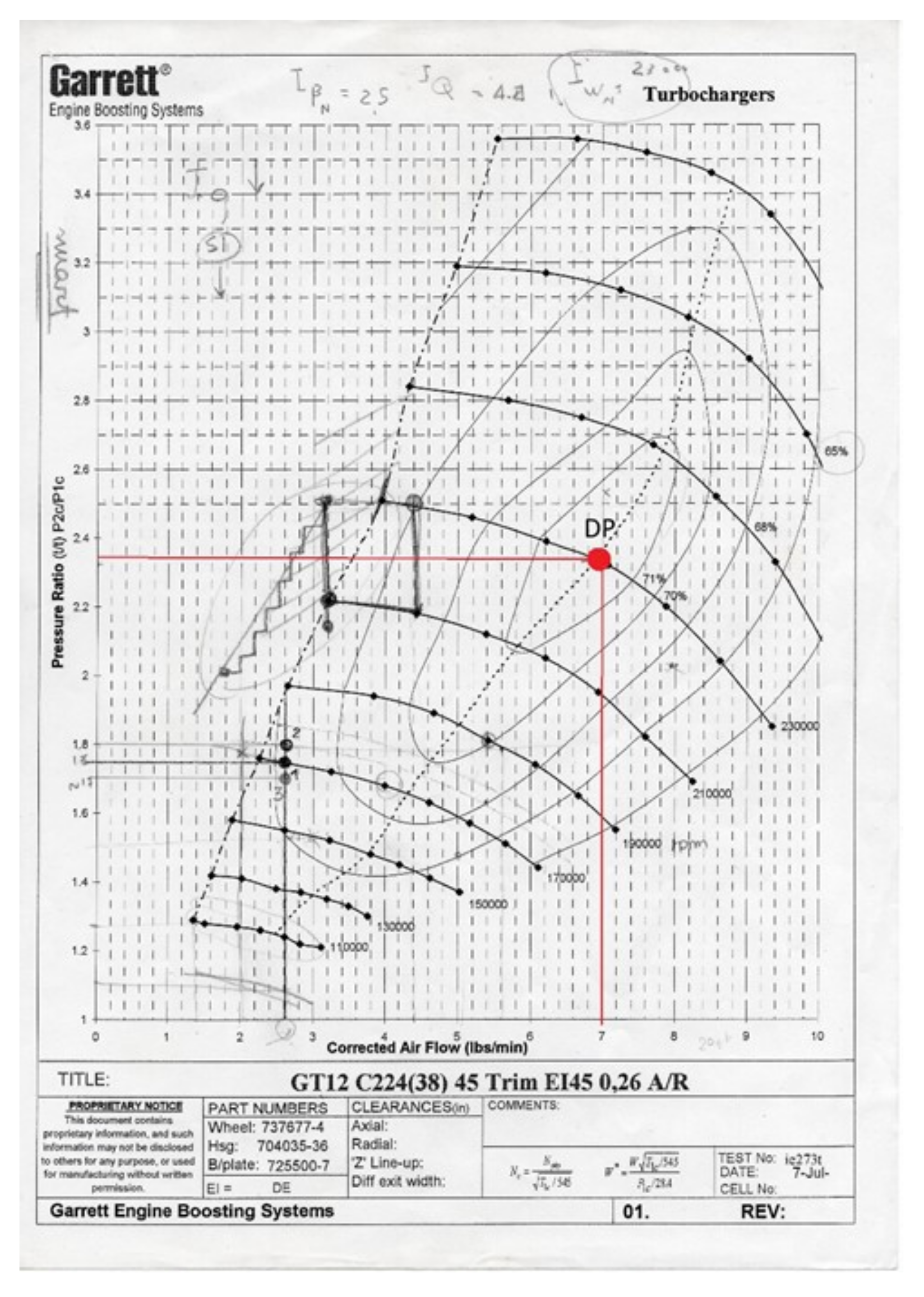
  • The final values of the analytical design for the conventional impeller were compared with the available data for the Garrett GT12 and found to agree with exceptional accuracy [7].

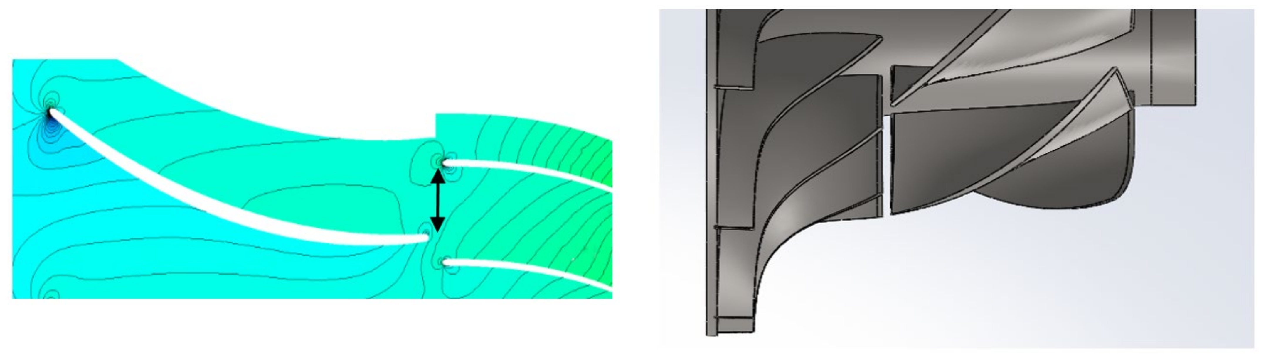
4.2. The Tandem Impeller Geometry

The tandem version of the GT12 impeller was designed with the same solid modelling tools described above, but the following modifications were introduced:
  • More accurate leading and trailing edge profiles for the inducer blade;
  • Both the inducer chord and stagger were made to vary spanwise;
  • The inducer maximum thickness, set to 3.5% of the chord, is located at mid-chord;
  • The exducer is obtained by trimming the original centrifugal blades on the inlet side until they reach the same chord length as the splitter blades: in practice, we are thus dealing with a 12-blade radial rotor (this geometry was modified later, see below, for better performance).

4.3. The Diffuser

Both the original GT12 turbocharger unit and the new tandem compressor are equipped with a vaneless diffuser.
  • The axial span of the diffuser is equal to the blade thickness at rotor exit;
  • The radial extension of the diffuser is the same as in the original GT12 compressor;
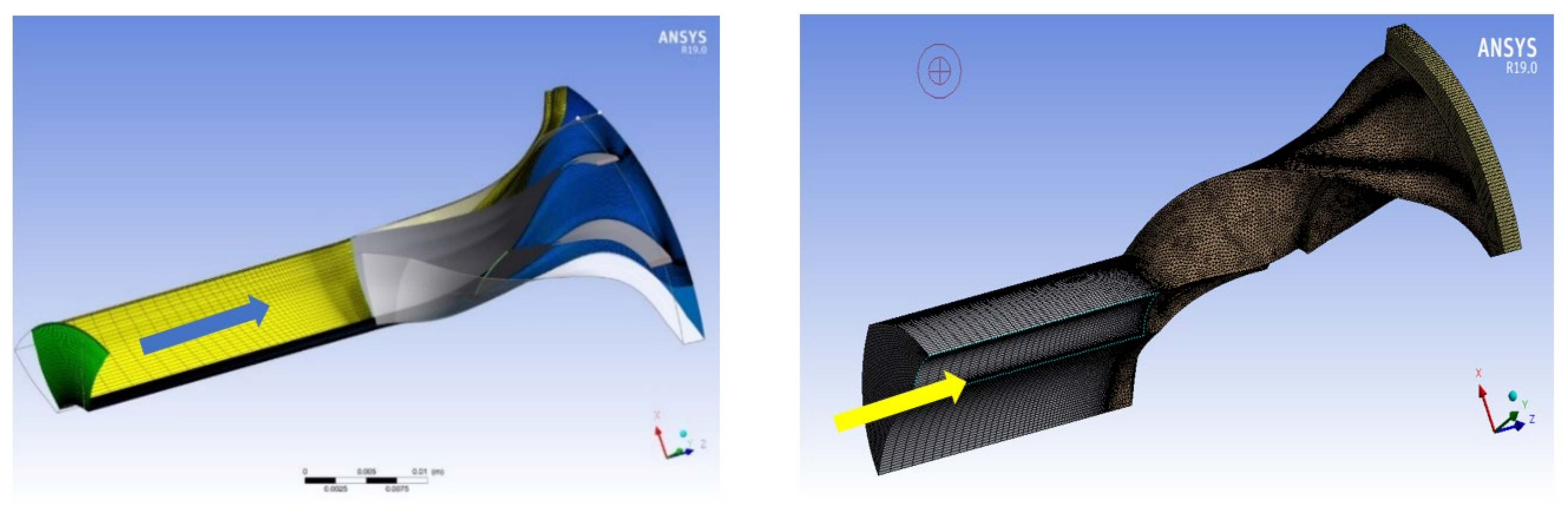
  • Again an extension of the domain by 1.5 diameters was introduced to smooth the downstream boundary condition (Figure 10);
  • The mixing plane method was used at the rotor/diffuser interface.

5. Performance Comparisons

The results of the CFD simulations of the original Garrett compressor were found to closely agree with the available performance data [7]. The main design specifications are:
  • Stationary flow: all parameters are assumed constant in time;
  • No preswirl at inlet: Vt = 0 on the inlet section;
  • Radially constant inlet meridional flow;
  • Air inlet conditions as in Table 1.

5.1. The Tandem Compressor

In order to make a proper comparison, the initial design point (DP) of the tandem rotor is set equal to that of the traditional design: maximum isentropic efficiency 0.71 and 100% revolution speed at 230,000 rpm (Inlet conditions in Table 1). The reduced mass flow rate at DP is imposed by the compressor operational map at 0.05598 kg/s, with a compression ratio β = 2.3. The main geometric features are reported in Table 2.
The inducer is treated as an axial compressor rotating solidly with the exducer, confined in the same shroud and with the same internal and external diameter as the intake of the original Garrett GT12. After a careful perusal of the available literature, its compression ratio was set to 1.2.
The standard quasi-two dimensional design method (velocity triangles) resulted though in a problematic geometry, and some modifications were necessary: a radius-dependent solidity was imposed, with the chord increasing slightly from hub to tip. Moreover, the incidence of the inducer blades was set to 2° to reduce the acceleration on the suction side of the leading edge.
The exducer geometry was also modified in the course of the study: the initial version “Tandem A”, after the first simulations was adjusted and then underwent a Design of Experiments (DOE) procedure (see Appendix A) that led to the development of the “B” and “C” geometries discussed below.
The tandem configuration has a higher degree of reaction than the Garrett GT12, and thus to obtain the required pressure recovery a change in the diffuser geometry was necessary: established theory [7] suggests to adopt an area ratio AR ≈ 5.7 and a slenderness ratio SR ≈ 1.3, which results in a recovery efficiency of about 0.6. Detailed design data are provided in [7], here we are concerned solely with the analysis of the flow field.
A mesh sensitivity analysis was run on each configuration, the objective function being the shaft torque. Quite obviously, the results are geometry-dependent (Figure 11): the final meshes contained 1.6 × 10⁶ and 1.2 × 10⁶ nodes for the standard and tandem rotor, respectively. The diffuser mesh contained 1.6 × 10⁵ (Garrett) and 1.2 × 10⁵ (Tandem) nodes. The final rotor meshes are shown in Figure 12.

5.1.1. CFD Results

The most interesting global result is the compressor characteristic. Figure 13 shows that the Tandem A configuration displays a better efficiency than the Garrett compressor over the entire operating range (except very close to the choking line). This result was expected, as it is also well-documented in the relevant literature [17]. Tandem A also attains higher compression ratios over the entire operating range (except very close to the choking line). This result will be justified below by a detailed examination of the flowfields. This configuration seems also to display a better resistance to stall (the efficiency is still high at lower mass flow ratios than its baseline counterpart). This result needs a more careful analysis on the basis of a detailed examination of the flowfields and will be discussed in the next section.
The relative Ma plots of Figure 14 show that the Tandem A rotor has substantially lower sonic losses at the intake, while at rotor exit the Ma profiles are similar. Both plots refer to 50% span near the choking limit [7]. In the original configuration (left) incipient choking is visible in the circled regions, where the local Ma is near or even in excess of one. The presence of the inducer provides a partial cure to this situation but reduces the critical mass flowrate (see also Figure 13). This undesired result is originated by the appearance of a jet flow (highlighted in Figure 15) between the pressure side of the inducer blade and the suction side of the exducer (where Ma ≈ 0.8): this high-speed flow flattens the boundary layer on the exducer suction side (improving work transfer in that area) but also distorts the pressure field, attracting some fluid from the suction side BL and maintaining its “jet” profile up to the rotor exit, resulting in high sonic losses.
A second undesirable characteristic of the Tandem A rotor is the mismatch between the velocity at inducer exit and the tangent to the chord of the exducer leading edge: this results in an excessive incidence that—at low flowrates—promotes BL separation on the pressure side of the exducer (Figure 15 and Figure 16). This effect is caused by the previously discussed decision of maintaining the exducer geometry of the conventional machine, to highlight the influence of the sole inducer on the flow field.
Both effects are clearly due to non-optimal design, and some improvements were introduced to generate a “Tandem A modified” configuration:
  • The inducer trailing edge and the exducer leading edge were made radial, to enforce a radially constant angular gap between the two blades;
  • The exducer stagger was redesigned to match the relative fluid flow at inducer exit;
  • The angular overlapping of the exducer was reduced to 40°, to increase the critical mass flowrate.
This modified design eliminated the two defects discussed above (see Figure 17 and Figure 18): the high-Ma regions near rotor exit are much less extended, the jet flow has disappeared and the inducer/exducer BL transition is much smoother. At this point it became clear that it would be possible to tune the two parameters that most influence the creation of a jet flow at the inducer/exducer interface, namely the axial clearance between the two (the larger this clearance, the more fluid “leaks” from the pressure to the suction side) and the “clock”, i.e., the circumferential angle between the two blades, which is the main factor controlling the interblade jet flow. Both are defined in Figure 19.
Therefore, after introducing the above corrections, a Design of Experiment campaign was conducted to identify the best clock/clearance combination. (see Appendix A)
Two improved designs were compared:
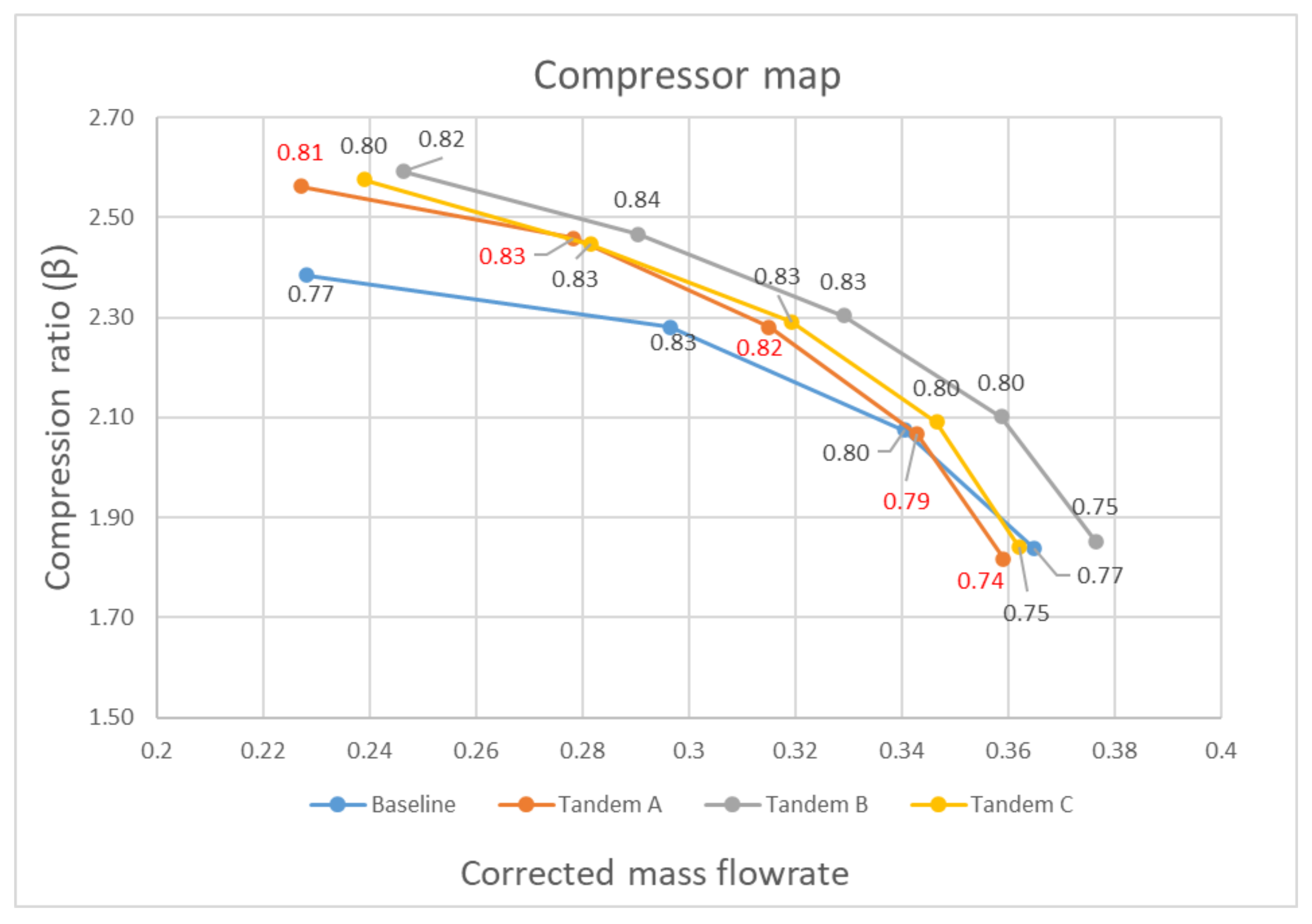
  • “Tandem B”: 75% clock and 0.5 mm of axial clearance, overlap 40°. Obtained by a Design-Of-Experiment (DOE) campaign;
  • “Tandem C”: 75% clock and 0.5 mm of axial clearance, overlap 50°.
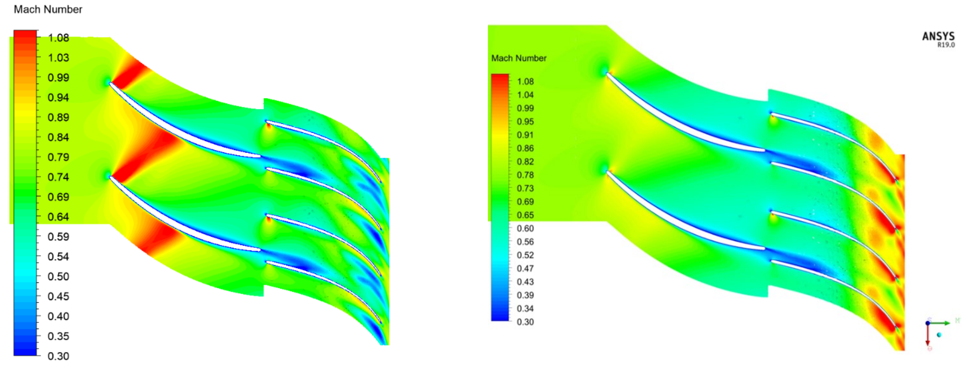
The B design (see Figure 13) shows a choke margin extension and outperforms the conventional impeller, while the C version (overlap increased to 50°) is slightly less efficient and just as sensitive to choking as the Garrett rotor, due to its higher Mach losses.

5.1.2. Discussion

Although it is intuitively clear that the most influential performance governing feature in a tandem compressor configuration is the interaction between the inducer boundary layer and the exducer blades, and it is also clear that in general the stage efficiency increases when the inducer boundary layer falls in the pressure side of the exducer, there seems to be no general agreement on how the circumferential (clock) and axial (gap) separation between inducer outlet and exducer inlet affect performance (Figure 19). A first clue is provided by the consideration that the compression ratio increases when the boundary layer at inducer exit merges with the one at exducer inlet on the suction side: our calculations show that this enhances the airfoil performance and promotes a smoother flow throughout the exducer, as shown in Figure 20 (see Appendix A).
The clock has a remarkable influence on this effect: the 0% clock configuration reflects perfectly the previous considerations, while both the 25% and 50% clock geometris are dominated by Mach losses generated at a throat appearing between the inducer trailing edge and the exducer leading (Figure 21). The peak Mach number increases with the decrease of the axial distance, degrading efficiency. From our analysis emerges that a 75% clock weakens the Mach over most of the domain, as it is apparent from the “cleaner” midchannel sections displayed in Figure 22. This configuration achieves the highest efficiency throughout the operating range (Figure 13 and Figure 23) and exhibits promising performance for a full-scale application.
As for the axial gap, all simulations consistently demonstrate that its increase favors the bleeding of the inducer BL from the exducer pressure side, decreasing the overall efficiency. The best balance between compression ratio and efficiency is obtained with a 0.5 mm clearance, that results in a particularly “clean” Mach field. The resulting final geometry is the one labeled Tandem B.

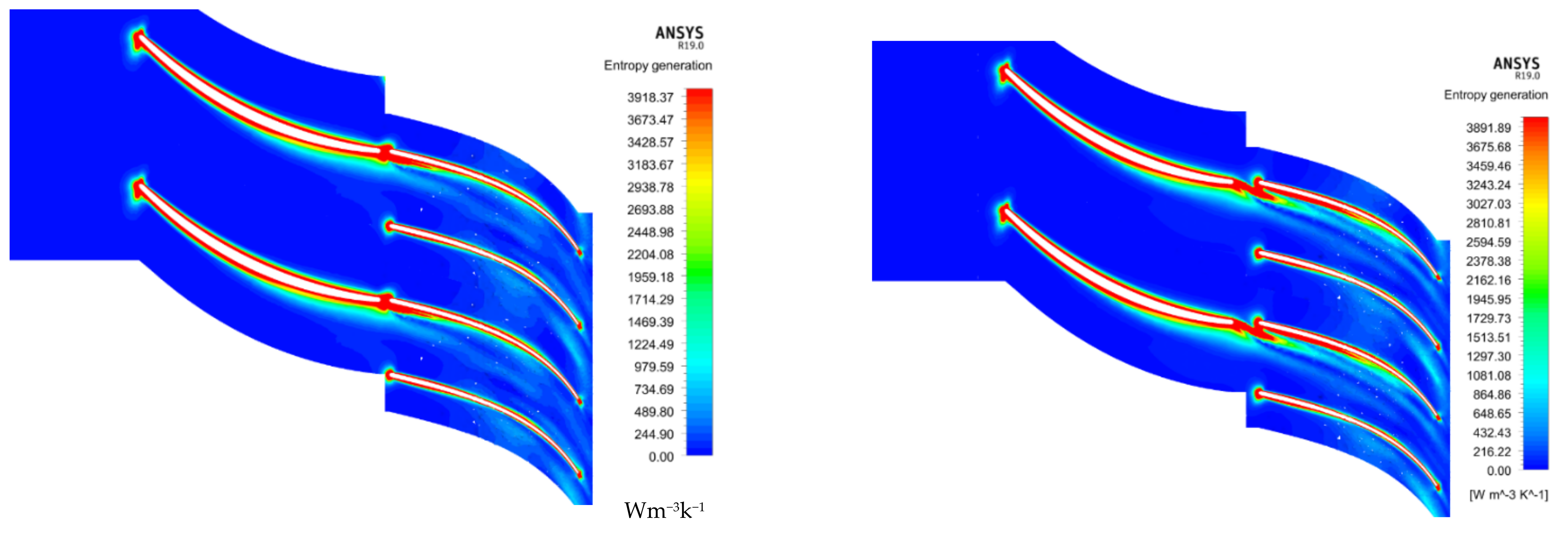
6. Maps of the Entropy Generation Rate

It is instructive to examine the entropy generation rate through the blade passages, to gain some more insight into the phenomenological reasons of the performance improvement with respect to the conventional configuration. According to the Gouy–Stodola theorem, the useful work (here, power) loss due to irreversibility is directly proportional to the entropy generation:
W ˙ l o s s , 0 = T 0 S ˙ g e n
where T0 is a fixed reference temperature, conveniently taken to be that of the surrounding environment. The rate of entropy generation contains a viscous and a thermal term, [23]:
s ˙ g e n = λ T 2 T 2 + μ T Φ   [ W / ( m 3 K ) ]
where λ and μ are the fluid thermal conductivity and dynamic viscosity respectively and Φ is the viscous dissipation function, modelled in the turbulent k-ε approximation adopted here and proportional to the turbulent dissipation rate. Figure 24 and Figure 25 shows the entropy generation maps at 50% span for the Tandem B configuration for 0% and 25% clock and 3 different values of the axial clearance.
It is apparent that increasing the clock decreases the coupling between the inducer wake and the BL developing on the pressure side of the exducer, reducing the mutual interferences and the compounding of the two dissipative effects. As a counterpart though, both the 25% and the 50% clock configurations are strongly influenced by the jet flow that decreases the performance with respect to the 0% case.
As for the axial clearance, while in the 0% clock an increase of the gap leads to some bleeding of the inducer BL towards the suction side, worsening the efficiency, in the 25% and 50% cases an increased clearance increases the throat section, lowering the Mach losses.
Figure 26 reports the same map for the “optimal” 75% clock configuration (Tandem B): here, the inducer wake energizes the BL on the pressure side of the exducer, flattening the BL on the pressure side of the exducer and providing a cleaner outlet. Above 50% clock the blade interaction does not contribute significantly to the Mach losses and, opposite to what happened for the 0%, there is no leaking of BL due to the relatively low axial gap between inducer and exducer.

7. Further Developments

Analyzing the choking behavior of the Tandem B geometry (Figure 27), it appears that the addition of the inducer leads to higher velocities downstream and through the exducer, shifting chocking towards lower mass flowrates.
This is contrary though to consolidated experience, since in conventional centrifugal compressors the shock should appear in the fore section of the blade, near the leading edge, and this indeed is the case for the GT12 conventional impeller (Figure 14). This odd behavior is thus the consequence of poor design, which in turn means that the exducer blade channel must be redesigned. A DOE procedure was again implemented in this final analysis of the tandem impeller, the parameters being now the blade overlapping angle and the meridional discharge section of the exducer. The best results were obtained with a blade overlapping of 40° that preserves a sufficiently high relative velocity in the channel to avoid the risk of suction side BL separation [7]. As an additional modification, the outlet meridional section of the exducer (“b” parameter [7]) was increased from 2.13 mm to 3 mm to ensure that the shock -if ever- will happen at inducer inlet.
In this second series of DOE analysis, the axial displacement has been kept constant to 0.5 mm. The results confirm the previous DOE campaign results but are not as crisp as in the previous cases. The result can be summarized as follows:
(1)
The 50% and 75% clock configurations show a better resistance to stall (upper left corner of Figure 28 right);
(2)
Choking characteristics are virtually independent on clock;
(3)
Whereas previous published results predicted higher efficiencies for 0% clock, in the high-flow regions the 75% clock is outperforming all other configurations (Figure 28, right).
The design choice emerging from the above described analysis will be called Tandem B.1 and has the following characteristics:
  • 40° blade overlapping angle;
  • b parameter equal to 3 mm;
  • Clock 75%;
  • Axial displacement 0.5 mm.
For clarity, Figure 29 presents a comparison between the compressor maps of Tandem B and B.1. The latter configuration displays a flatter characteristic, maintains a reasonably high efficiency, especially in the high-flow region, attains a higher compression ratio at all flowrates, delays chocking and expands operation in the stall region, albeit at a non-negligible efficiency loss.
On a practical side, these results indicate that a tandem compressor must be designed as such, and that a simple” refurbishing” of an existing compressor does not lead to a real performance optimization.

8. Conclusions

A new tandem radial compressor for a hybrid compound turbocharger has been designed starting from the one mounted on the Garrett GT12. The new compressor is to be installed in an electrically-driven turbocharger for a small hybrid car engine. An extensive series of CFD simulations led to the identification of a possible set of improved configurations, which were then heuristically “optimized” by means of a DOE procedure. In the process, the importance of two fundamental design parameters, the “clock” (circumferential offset between inducer exit and exducer inlet) and the “gap” (axial distance between the same two) was detected and quantified, and the relevant phenomenology effectively identified. Though the DOE process is not an “optimization” proper, but rather a heuristically guided succession of improvements, the final configuration displays a higher compression ratio than the original unit with an improved surge margin and a lower sensitivity to choking. A particularly interesting result is that this “optimal” tandem compressor geometry has an extremely high value of the circumferential offset between inducer and exducer blades (“clock”, equal to 75% here), and this contrasts with previous investigations that favored the “0-clock” configurations.

Author Contributions

Conceptualization, E.S.; methodology, N.C. and E.S.; software simulations, N.C.; validation, N.C. and E.S.; formal analysis, N.C. and E.S.; resources, E.S.; writing—original draft preparation, N.C.; writing—review and editing, N.C. and E.S.; supervision, project administration and funding acquisition, E.S. All authors have read and agreed to the published version of the manuscript.

Funding

This research was partially funded by PRIN 2017, grant number 20178RlFE.

Conflicts of Interest

The authors declare no conflict of interest.

Nomenclature

Symbol and UnitsDefinitionSymbol and UnitsDefinition
ARDiffuser area ratio (Exit/Inlet)S, W/°K;
s, W/(kg°K)
Entropy, specific entropy
BLBoundary LayerSFC, kg/sSpecific fuel consumption
CFDComputational Fluid DynamicsSRDiffuser slenderness ratio (length/inlet diameter)
DOEDesign of ExperimentsT, KTemperature
ECUElectronic Control UnitW, JMechanical work
K, J/kgTurbulent kinetic energyβPressure ratio
K, J/kgTurbulent kinetic energyε, W/kgTurbulent dissipation
KERSKinetic Energy Recovery Systemλ, W/(m°K)Thermal conductivity
m, kg/sMass flowrateμ, kg/(ms)Dynamic viscosity
NGVNozzle guide vanesϕ, W(m3°K)Viscous dissipation function
P0,T0 (Pa, K)Thermodynamic Inlet conditions--
K = 1.4Polytropic transformation coefficient--
D0 (m)Inlet compressor diameter--
R = 287 J/Kg∙KThermodynamic gas constant --
m (kg/s)Mass flow in --

Appendix A

As previously stated, the tandem impeller performance depends on two fundamental geometric parameters, the axial displacement and the clock, the latter being defined here as the angular offset between inducer pressure side and exducer suction side, expressed as a percentage of the blade angular pitch of the exducer. To identify possible “best” combinations of the two, a DOE-assisted series of numerical experiments was launched to better link each gap/clock combination to phenomena of the ensuing fluid flow. Three axial gaps have been tested: 0.5, 1, and 1.5 mm. Starting from a perfect inducer-exducer alignment (clock 0%) three clock configurations have been studied: 25%, 50%, and 75%. Each one of the resulting twelve clock/gap combinations has been simulated. The simulations are conducted at the expected design point with pre-assigned total pressure inlet and static pressure outlet. The results are shown in Figure A1 and Figure A2, and some of the corresponding flow fields are displayed in the main text of this paper.
Figure A1. Compression Ratio as a function of gap and clock.
Energies 14 02890 g0a1
Figure A2. Corrected mass flow as a function of gap and clock.
Energies 14 02890 g0a2

References

  1. Hu, B.; Turner, J.W.; Akehurst, S.; Brace, C.; Copeland, C. Observations on and Potential Trends for Mechanically Supercharging a Downsized Passenger Car Engine: A Review. Proc. Inst. Mech. Eng. Part D J. Automob. Eng. 2017, 231, 435–456. [Google Scholar] [CrossRef] [Green Version]
  2. Patil, C.; Varade, S.; Wadkar, S. A Review of Engine Downsizing and Its Effects. Int. J. Curr. Eng. Technol. 2017, 7, 319–324. [Google Scholar]
  3. Capata, R. New power train concept for a city hybrid vehicle. Proceedings 2020, 58, 6. [Google Scholar] [CrossRef]
  4. Muqeem, M.; Manoj, K. Turbocharging of IC engines: A review. Int. J. Mech. Eng. Technol. 2013, 4, 142–149. [Google Scholar]
  5. Heywood, J.B. Internal Combustion Engine Fundamentals; McGraw-Hill Education: New York, NY, USA, 2016. [Google Scholar]
  6. Capata, R.; Sciubba, E. Study, Development and Prototyping of a Novel Mild Hybrid Power Train for a City Car: Design of the Turbocharger. Appl. Sci. 2021, 11, 234. [Google Scholar] [CrossRef]
  7. Cuturi, N. CFD Analysis of a Radial Compressor Stage with Inducer Blades. Master’s Thesis, Department of Mechanical and Aerospace Engineering, University of Roma Sapienza, Rome, Italy, 2020. [Google Scholar]
  8. Ju, Y.P.; Zhang, C.H. Design Optimization and Experimental Study of Tandem Impeller for Centrifugal Compressor. J. Propuls. Power 2014, 30, 1490–1501. [Google Scholar] [CrossRef]
  9. Mohtar, H. Increasing Surge Margin of Turbocharger Centrifugal Compressor Automotive. Ph.D. Thesis, Ecole Centrale de Nantes, Nantes, France, 2010. [Google Scholar]
  10. Koch, C.C.; Smith, L.H., Jr. Experimental Evaluation of Outer Case Blowing or Bleeding of Single Stage Axial Flow Compressors, Part III: Performance of Blowing Insert Configuration No. 1. NASA CR-54589; 1968. Available online: https://ntrs.nasa.gov/api/citations/19690006778/downloads/19690006778.pdf (accessed on 15 April 2020).
  11. Brent, J.A. Single Stage Experimental Evaluation of Compressor Blading with Slots and Vortex Generators, Part III: Data and Performance for Stage 4; NASA CR-72741; NASA: Washington, DC, USA, 1970. [Google Scholar]
  12. Boyce, M.P.; Nishida, A. Investigation of Flow in Centrifugal Impeller with Tandem Inducer; Paper 43; Japan Society of Mechanical Engineering: Tokyo, Japan, 1977. [Google Scholar]
  13. Josuhn-Kadner, B.; Hoffman, B. Investigation on a Radial Compressor Tandem Rotor Stage with Adjustable Geometry. J. Turbomach. 1993, 115, 552–559. [Google Scholar] [CrossRef]
  14. Roberts, D.A.; Kacker, S.C. Numerical Investigation of Tandem-Impeller Designs for a Gas Turbine Compressor. J. Turbomach. 2002, 124, 36–44. [Google Scholar] [CrossRef]
  15. Bammert, K.; Staude, R. New Features in the Design of Axial-Flow Compressors with Tandem Blades. In ASME 1981 International Gas Turbine Conference and Products Show; ASME Digital Collection: New York, NY, USA, 1981. [Google Scholar]
  16. Qureshi, S.R.; El-Leathy, A.; Ud-Din, K.S.; Umer, U.; Chaochen, M.; Danish, S.N. Numerical Investigation and Comparison of a Tandem-Bladed Turbocharger Centrifugal Compressor Stage with Conventional Design. Int. J. Therm. Sci. 2014, 23, 523–534. [Google Scholar]
  17. Erdmenger, R.R.; Michelassi, V. Influence of Tandem Inducers on the Performance of High Pressure Ratio Centrifugal Compressors; ASME Paper GT2015-43001; ASME Digital Collection: New York, NY, USA, 2015. [Google Scholar] [CrossRef]
  18. Hanus, D.; Censky, T.; Neveceral, J.; Horky, V. First stage of the centrifugal compressor design with tandem rotor blades. In Proceedings of the ISABE–17th International Symposium on Airbreathing Engines, Munich, Germany, 4–9 September 2005. Paper 1161. [Google Scholar]
  19. Hlavá, D.; Hanus, D. Results of the Development of a Tandem-Bladed Centrifugal Compressor Stage; Studentská Tvůrčí Činnost. 2016. Available online: http://stc.fs.cvut.cz/pdf16/6520.pdf (accessed on 19 March 2019).
  20. Li, Z.; Lu, X.; Zhang, Y.; Han, G.; Yang, C.; Zhao, S. Numerical investigation of a highly loaded centrifugal compressor stage with a tandem bladed impeller. J. Power Energy 2018, 232, 240–253. [Google Scholar] [CrossRef]
  21. Li, Z.-L.; Lu, X.-G.; Zhao, S.F.; Han, G.; Yang, C.-W.; Zhang, Y.-F. Numerical Investigation of Flow Mechanisms of Tandem Impeller inside a Centrifugal Compressor. Chin. J. Aeronaut. 2019, 32, 2627–2640. [Google Scholar] [CrossRef]
  22. Silvestri, T. CFD Analysis of a Radial Turbine Stage with Variable NGV Control. Master’s Thesis, Department of Mechanical and Aerospace Engineering, University of Roma Sapienza, Rome, Italy, 2020. [Google Scholar]
  23. Bejan, A. Entropy Generation through Heat and Fluid Flow, 1st ed.; John Wiley & Sons, Inc.: Hoboken, NJ, USA, 1982. [Google Scholar]
Figure 1. Standard Turbocharger assembly.
Energies 14 02890 g001
Figure 2. The supercharged indicated cycle.
Energies 14 02890 g002
Figure 3. Garrett GT1238 compressor map.
Energies 14 02890 g003
Figure 4. Garrett GT1238 turbine map.
Energies 14 02890 g004
Figure 5. Schematic representation of clock (Δys) and axial displacement (Δxs).
Energies 14 02890 g005
Figure 6. The turbocharged W451, 998 cc, 62 kW engine.
Energies 14 02890 g006
Figure 7. Hybrid Turbo-Compound concept.
Energies 14 02890 g007
Figure 8. The original GT 12 impeller (left) and the new tandem geometry (right).
Energies 14 02890 g008
Figure 9. Tandem rotor CFD fluid domain.
Energies 14 02890 g009
Figure 10. Diffuser CFD fluid domain.
Energies 14 02890 g010
Figure 11. Mesh sensitivity for the conventional (left) and tandem compressor (right).
Energies 14 02890 g011
Figure 12. The final mesh for the conventional (left) and tandem compressor (right). Arrows indicate flow direction.
Energies 14 02890 g012
Figure 13. Characteristic curves for the conventional and tandem compressor.
Energies 14 02890 g013
Figure 14. Relative Ma contours for the conventional (left) and tandem compressor (right).
Energies 14 02890 g014
Figure 15. Excessive incidence on the exducer leading edge, mr = 0.32.
Energies 14 02890 g015
Figure 16. Recirculation on the exducer pressure side, mr = 0.32.
Energies 14 02890 g016
Figure 17. Effects of the incidence correction mr = 0.36. Countour of Mach number (left) and velocity vector plot (right).
Energies 14 02890 g017
Figure 18. Relative Mach number contours at 50% span in tandem A (left) and Tandem B (right) (mr = 0.35).
Energies 14 02890 g018
Figure 19. Graphical representation of “clock” (left) and “clearance” (right).
Energies 14 02890 g019
Figure 20. Relative velocity maps for 0% clock, clearance 0.5 mm (left) and 1.5 mm (right). mr = 0.33.
Energies 14 02890 g020
Figure 21. Mach number for 25% clock, clearance 0.5 mm (left) and 1.5 mm (right). mr = 0.35.
Energies 14 02890 g021
Figure 22. Entropy generation map (left) and Mach number (right) for 75% clock, 0.5 mm clearance. mr = 0.33.
Energies 14 02890 g022
Figure 23. Axial inducer/exducer clearance vs. efficiency.
Energies 14 02890 g023
Figure 24. Entropy generation map at 50% span, 0% clock. Axial gap 0.5 mm (A), 1 mm (B), and 1.5 mm (C). mr = 0.33.
Energies 14 02890 g024
Figure 25. Entropy generation map at 50% span, 25% clock. Axial gap 0.5 mm (A), 1 mm (B), and 1.5 mm (C), mr = 0.33.
Energies 14 02890 g025aEnergies 14 02890 g025b
Figure 26. Entropy generation map at 50% span, 75 % clock, 0.5 mm gap configuration mr = 0.33.
Energies 14 02890 g026
Figure 27. Mach number contour at choking condition, Impeller with blade channel modification (left) and without (right).
Energies 14 02890 g027
Figure 28. Graphical results of second generation DOE campaign. Isentropic efficiency-Corrected mass flowrate Plot (left), Characteristic map of the second generation of impellers (right).
Energies 14 02890 g028
Figure 29. Compressor map comparison.
Energies 14 02890 g029
Table 1. Air inlet conditions (British units shown for comparison with original Garrett documentation).
Inlet pressure (p1)Pa101,000
Inlet temperature (T1)K298
Intake mass flow rate, Design Point (kg/s)0.05598
Corrected mass flow, Design Point(lb/min)7.00
Table 2. Main Features of the Tandem Compressor rotor.
UnitValue
Inducer tip diameter (D1)mm22.47
Inducer hub diameter (D1i)mm8.20
Exducer tip diameter (D2)mm38.00
Blade tip span (b)mm2.38
Zn-6 + 12
Publisher’s Note: MDPI stays neutral with regard to jurisdictional claims in published maps and institutional affiliations.

