Article

Reduction of Cogging Torque in Surface Mounted Permanent Magnet Brushless DC Motor by Adapting Rotor Magnetic Displacement

Department of Electrical and Electronics Engineering, SRM Institute of Science and Technology, SRM Nagar, Kattankulathur 603203, India
*
Author to whom correspondence should be addressed.
Energies 2021, 14(10), 2861; https://doi.org/10.3390/en14102861
Submission received: 22 March 2021 / Revised: 26 April 2021 / Accepted: 10 May 2021 / Published: 15 May 2021
(This article belongs to the Special Issue Wireless Power Transfer for Electric Vehicles)

Abstract

:
Cogging torque is a critical dilemma in Permanent Magnet Brushless DC (PMBLDC) motors. In medium-low power PMBLDC motors, redundant vibrations and forbidding noises arise as a result of the harmonic magnetic forces created by cogging torque. This paper introduces a simple approach for minimizing cogging torque in PMBLDC motors by applying placement irregularities in rotor magnets. An angle shift in the rotor magnets in surface-mounted PMBLDC motors helps to attain magnet displacement. This displacement imparts an asymmetrical magnet structure to the rotor. Maintaining pole arc to pole pitch ratio (L/τ) of between 0.6 and 0.8, shifting angles from 1° to 8° were considered in order to analyze the effect of the angle shift on the rotor magnets. An analytical expression was also derived for finding the shifting angle with the minimum cogging torque in the PMBLDC motor by using the Virtual Work Method (VWM). The optimization of the shifting angle with minimum cogging torque was investigated using 3D Finite Element Analysis (FEA). A comparison of the simulation and analytical results of cogging torque was carried out. It was determined that the reduction of cogging torque in the analytical results showed good agreement with the FEA analysis.

1. Introduction

Permanent Magnet Brushless DC (PMBLDC) motors are machines with excellent torque–speed characteristics, excellent efficiency, and nominal maintenance cost. They are very favorable for unidirectional variable-speed applications such as automotive pumps and fans [1]. They are also very supportive with respect to achieving compactness in terms of machine size [2]. They produce a negligible amount of electromagnetic and mechanical noise. They also exhibit excellent durability due to their lack of mechanical contact [3]. One of the great flaws in the BLDC motor is its torque ripple, which is built into the design [4]. One of the main reasons for torque ripple is cogging torque. Cogging torque also generates enormous, troubling noise and shaking movements in the machine itself, as well as in its load. For this reason, cogging torque reduction methods play a vital role in PMBLDC motor design. Generally, cogging torque derives from motors using permanent magnets such as Permanent Magnet Brushless DC (PMBLDC) motors and permanent Magnet Synchronous motors. The root cause for the generation of cogging torque in BLDC motors is the magnetic interaction between the permanent magnet and the steel in the slotted armature. A lot of techniques are currently available for the minimization of cogging torque in BLDC motors. Nowadays, BLDC motors are used in rigorous applications such as electric power steering, robotics, etc. Hence the reduction of cogging torque has come to be a grueling task.
Over the last two decades, numerous studies have been conducted on the cogging torque of PMBLDC motors. These methods have included electromagnetic methods and mechanical methods. The authors recommended a core skew structure for reducing the cogging torque in [5]. When applying this property, no-load THD and the fifth and seventh harmonics were the main harmonic components of the back-EMF. However, when skewing the core, some residual magnetism is lost. Modification of the machine’s magnetic circuit resulted in the occurrence of additional harmonics in the cogging torque in [6]. They focused on a symmetrical rotor with an asymmetrical stator or an asymmetrical rotor with a symmetrical stator. Nonlinear algorithms were proposed for the reduction of cogging torque in [7,8,9]. A feedback linearization strategy was used in [7], mathematical modeling of cogging torque phenomena was performed in [8], and field-oriented control operations were used in [9]. A new technique for radial flux surface-mounted PMBLDC motors was proposed by applying T-shaped bifurcations in the stator teeth in [10]. However, this reduced the mechanical strength of the stator. In order to reduce the cogging torque, the slot was closed by a sliding separator in [11]. For small-sized machines, it is very difficult to place a slider inside the slot. The authors recommended notches in the rotor in [12]. However, adding notches in the rotor side is a tedious mechanical process. A new technique in the winding side was proposed in [13]. Coil winding concentrated on the phase group is a good solution for cogging torque reduction, but increases the complexity of the winding. Magnet step skewing and reduction of the claw pole width was carried out in a claw pole machine in [14]. Magnet step skewing causes a reduction in residual magnetism and the unequal width in the claw pole increases the structural complexity. U-clamped magnetic poles were recommended for the reduction of cogging torque and even flux per pole in [15], so a machine with a greater number of slots is recommended, as well as a high magnet thickness. In [16], a novel air gap profile was introduced for a single-phase PMBLDC motor. This air gap profile consists of a dip and a dip angle. By varying the dip and dip angle, a handful of air gap profiles could be generated, and profiles with a dip angle less than the critical dip angle exhibited improved starting torque by up to 70%. In [17], the reduction of cogging torque and acoustic noise in permanent magnet motors with larger stator slot openings was investigated. Here also, tooth pairings with two different types of tooth width were proposed. The experimental results showed that the proposed tooth pairings reduced cogging torque by 85% and acoustic noise by 3.1 dB. Reference [1] showed how to minimize high cogging torque without increasing the manufacturing cost. A systematic means was presented by which the selected introduction of auxiliary slots can double the fundamental frequency of the cogging torque, making stator claw skewing much more effective at reducing cogging torque; both measures can feasibly be carried out at the stage of punching the steel sheets and their subsequent deep drawing, at no additional cost. Reference [18] reported a stator shape optimization design for reducing the cogging torque of single-phase brushless DC (BLDC) motors by adopting an asymmetrical airgap to make them self-start. A model that combined Latin hypercube sampling and a genetic algorithm was used to reduce the cogging torque and maintain the efficiency and torque. As an optimal design result, the cogging torque of the optimal model decreased. Ref. [19] proposed a new design of SPOKE-type PM brushless direct current (BLDC) motor without using neodymium PM (Nd-PM). The proposed model had an improved output characteristic, as it used the properties of the magnetic flux effect of the SPOKE-type motor with an additional pushing assistant magnet and sub assistant magnet in the shape of a spoke. In this paper, ferrite PM (Fe-PM) was used instead of Nd-PM. The authors of [20] introduced a genetic algorithm for optimal core shape design for reducing cogging torque in brushless DC motors used in digital versatile disk drive systems or hard disk drive systems. The optimized or rounded core could be a recommended core shape for the outer-rotor-type BLDC motor for a DVD ROM drive system in order to achieve low cogging torque. Ref. [21] described a novel rotor pole shape consisting of a uniform surface and an eccentric surface, leading to a sinusoidal magnetic flux density in the air gap and reducing cogging torque, torque ripple, and the harmonics of the back-electromotive force waveform in a spoke-type brushless DC motor. This novel rotor included an eccentric surface. The proposed method had a smooth variation of reluctance, producing a near sinusoidal magnetic flux waveform in the air gap. This caused a reduction in the losses between the upper edge of the permanent magnet and the adjacent stator teeth, and an increment of the effective flux by concentrating the flux. Ref. [22] proposed an anisotropic ferrite magnet shape and magnetization direction to maximize back-EMF in an IPM BLDC motor. Firstly, four different models of general magnet shapes were selected, and then FEM analysis was carried out using four different magnetization directions for each of the four models. The best magnet shape and magnetization direction for each model was used to determine an initial model for optimization. Secondly, based on the initial model, optimization design for maximum back-EMF and minimum cogging torque and THD was performed. Reference [23] presented the stator and rotor shape designs for an interior-permanent magnet (IPM)-type brushless DC (BLDC) motor for reducing torque fluctuation. A partly enlarged air gap is introduced by the unequal diameter of the rotor and core structure of the stator with pole shoe modification. A reduction in torque ripple was obtained by upgrading the torque value at the minimum torque position, and their detail characteristics were compared. The addition of holes in the rotor core is a better solution for overcoming this problem. The additional torque fluctuation was decreased.
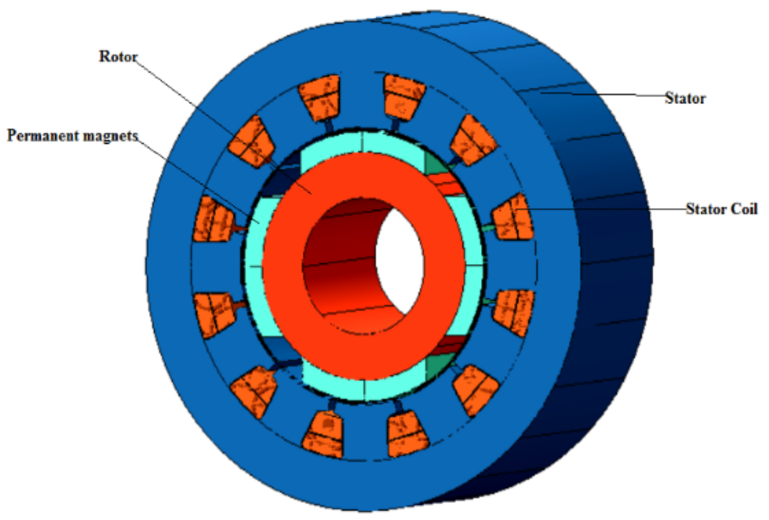
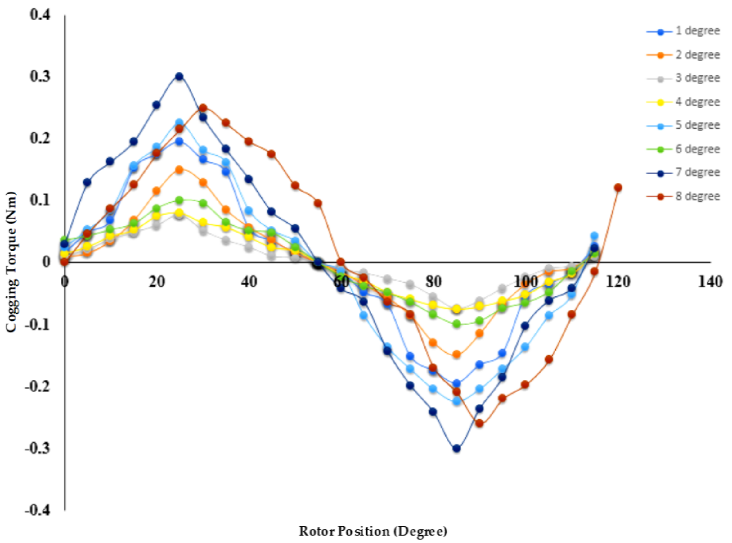
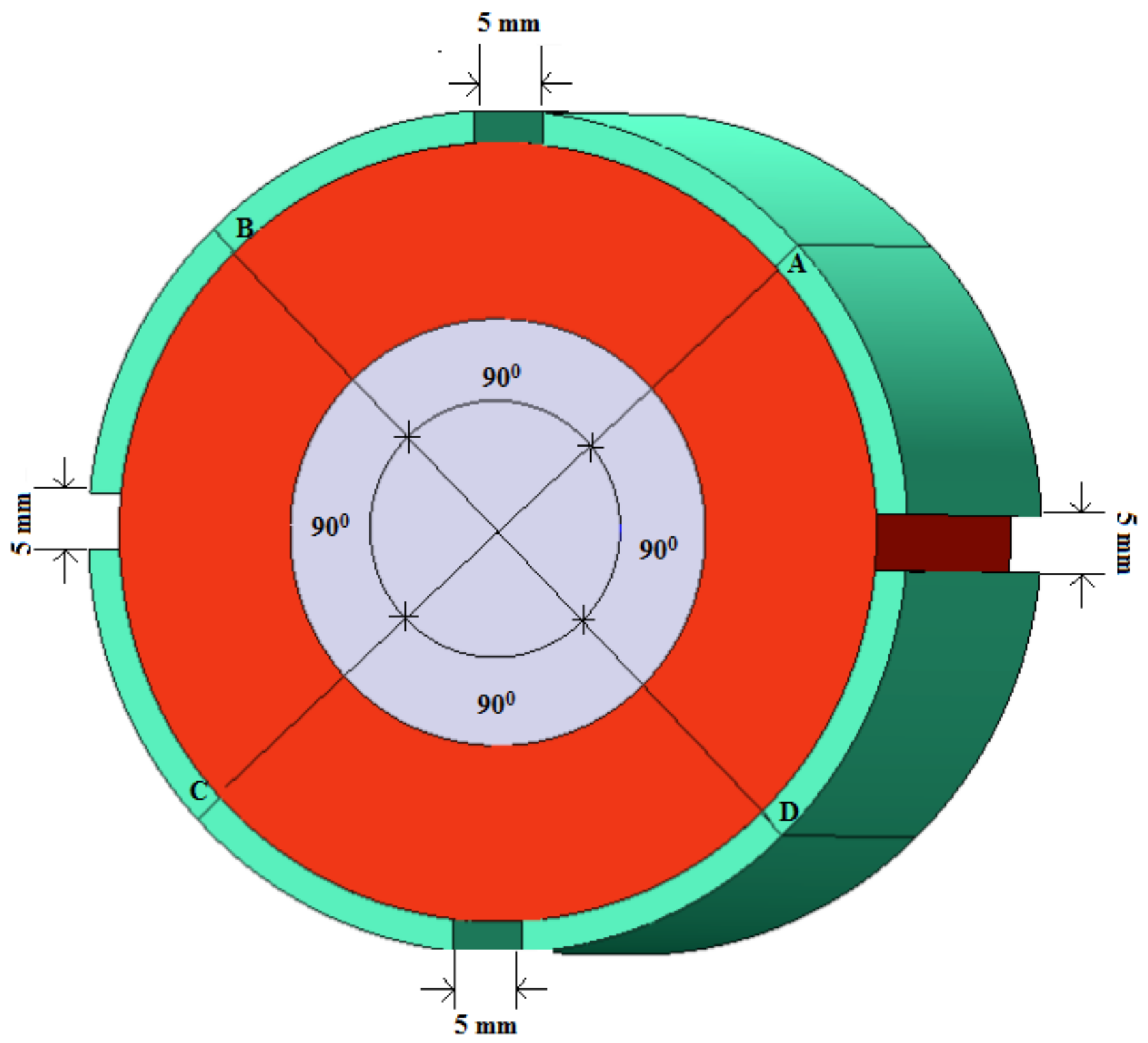
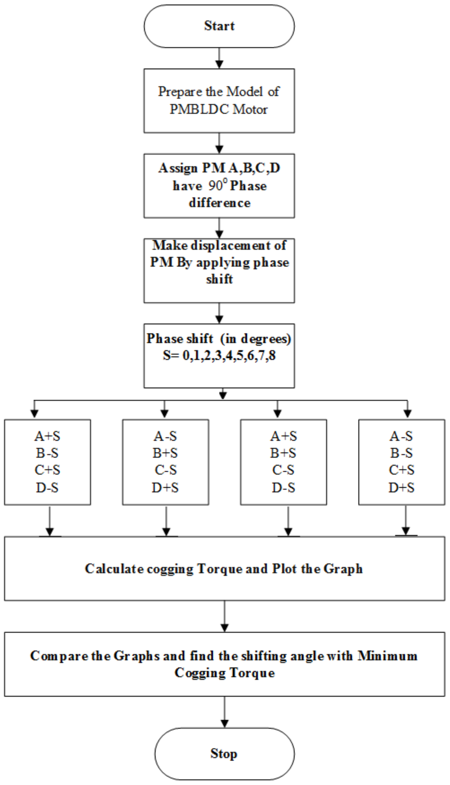
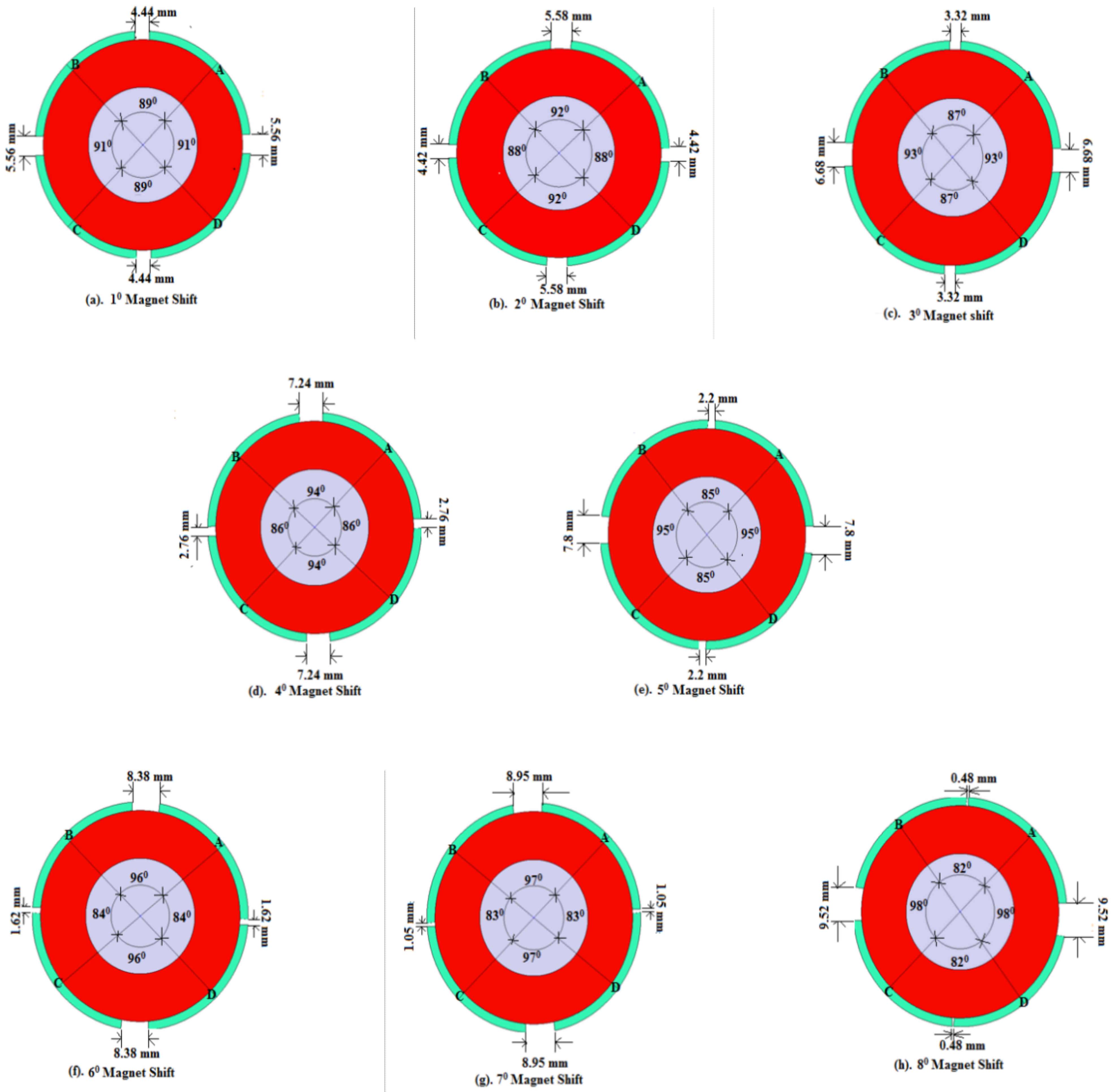
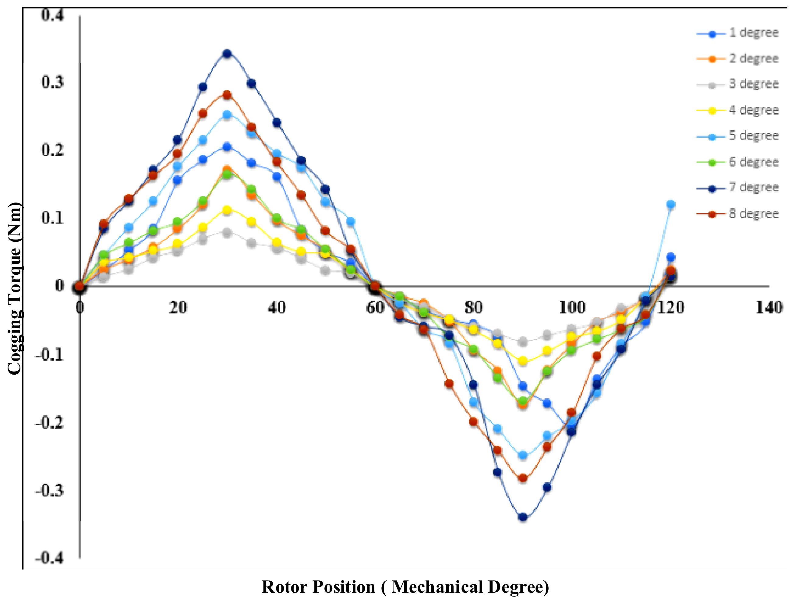
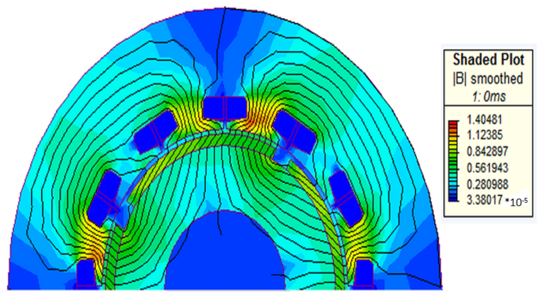
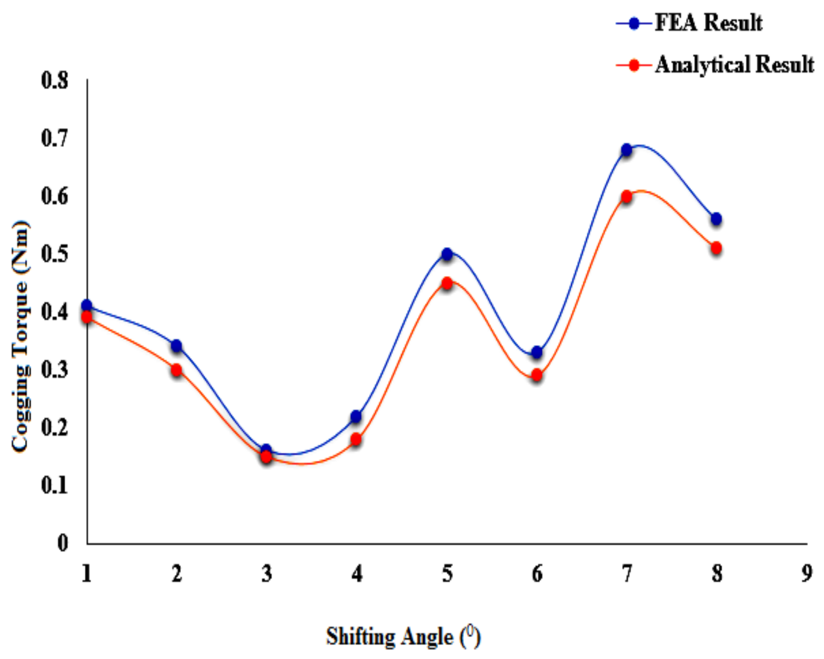
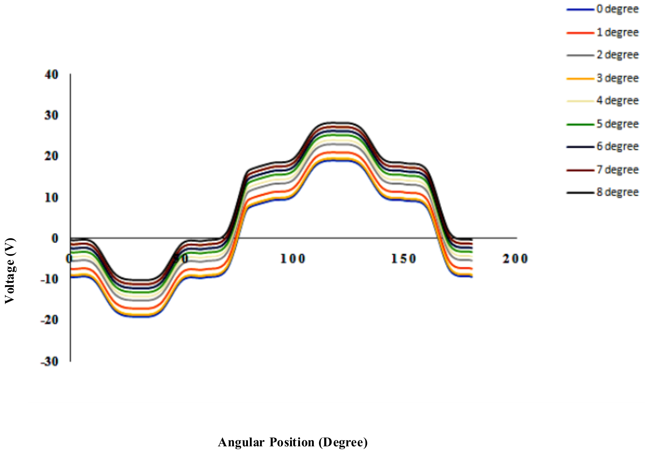
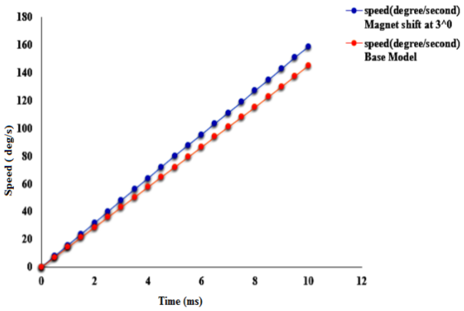
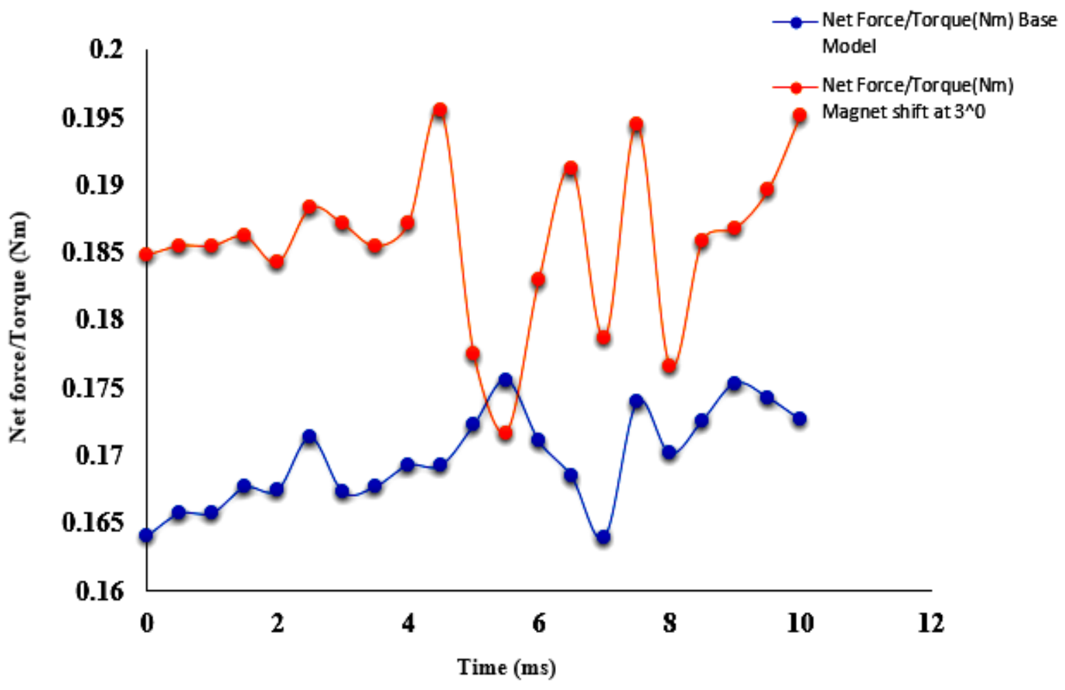
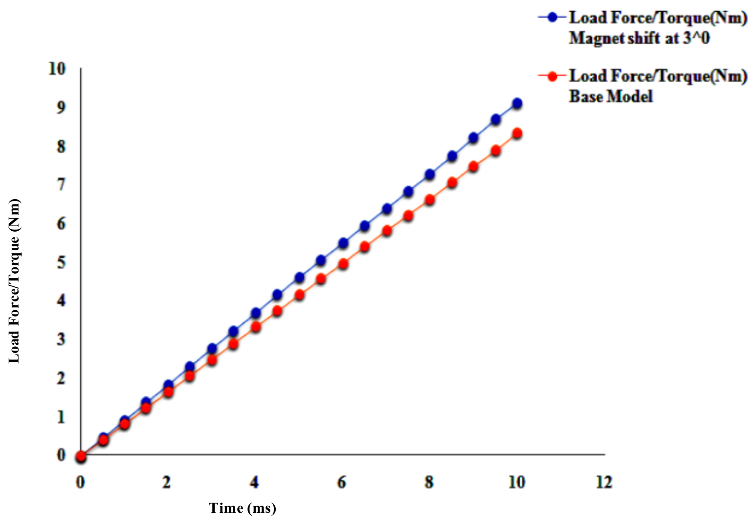
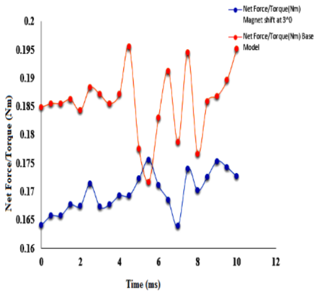
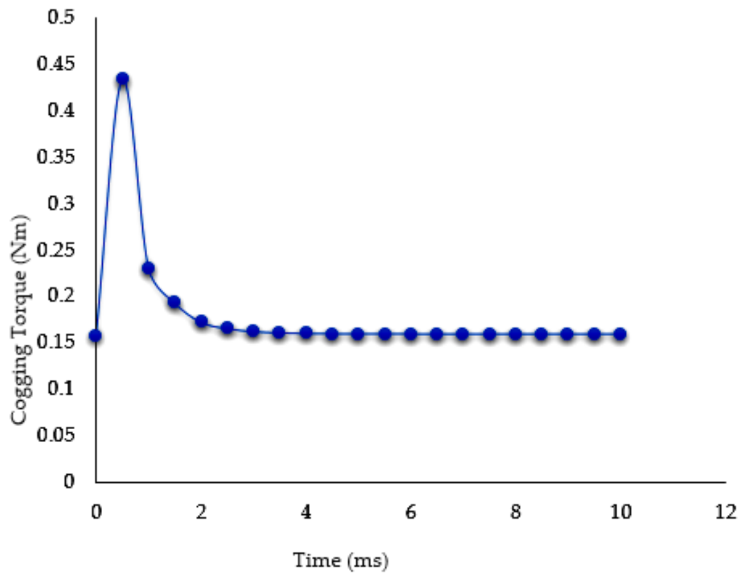
In the context of the exploration of different cogging torque reduction methods, motors with asymmetrical magnets represent a productive technique. This paper introduces a novel design based on an asymmetrical rotor structure by applying a shifting angle to the PM. The shifting angle method is not a skewing method, where the skew technique is used for skewing the rotor PMs. The shifting angle method alters the position of the permanent magnet by changing the pole pitch. To analyze the effect of magnets shifting in the BLDC motor, 3D-FEA analysis and numerical analysis were performed. To study the impact of varying the angle between the permanent magnet on the rotor, a range of different angles were considered. The rotor permanent magnet was shifted from 1° to 8°. To effectively decrease the cogging torque, an optimal 3° shift to the permanent magnet (AB-87°, BC-87°, CD-93°, and DA-93°) was determined. The resulting design also obtained the correct trapezoidal shape of the back-EMF. Compared to the reference model, it was able to achieve a 60% reduction in cogging torque. This method is able to achieve excellent performance characteristics. The simulation results were compared with the analytical results, and the reduction of cogging torque in the two analyses was almost the same.
The organization of the paper is as follows: the design of the BLDC motor is presented in Section 2. The analytical expression of cogging torque by VWM is presented in Section 3. Finite element analysis of the symmetrical rotor is presented in Section 4. The effect of the angle shift on cogging torque is shown in Section 5.

2. Design of BLDC Motor

The basic step in the motor design is to fix the rated speed and torque. Based on these particulars, the other parameters of the motor can be selected. Figure 1 shows the structure of a surface-mounted PMBLDC motor.
The stators of BLDC motors are similar to those of three-phase induction motors. The main dimensions depend on the specific electric loading and specific magnetic loading. The procedure for calculating the main dimensions is depicted as a flowchart in Figure 2. The procedure for the selection of stator slots and winding is shown in Figure 3.
In this paper, in order to analyze cogging torque reduction, a 4-pole, 12-slot surface- mounted BLDC motor was used. The design parameters of the motor are shown in Table 1.

3. Analytical Expression of Cogging Torque by VWM

The most widely used method for calculating cogging torque is the virtual work method (VWM). The virtual work method is also called the co-energy method [24]. The basic principle is that neglecting the variation in magnets and iron of PMBLDC motor, the cogging torque of an ideal lossless PMBLDC motor can be expressed as the derivative of co-energy in the air gap [25]. According to [26], cogging torque is produced because of the interaction between the PMs and the armature and the slot. Because of this interaction in the absence of a current, energy variation occurs inside the motor.
E v = E v . I + E v . a i r g a p + E v . P M
where E v is the total energy variation, E v . I is the energy variation in iron,   E v . a i r g a p is the energy variation in airgap, and   E v . P M is the energy variation in PM.
When compared with the energy variation in the airgap and PM, only a minor variation occurs in iron. Therefore
E v E v . a i r g a p + E v . P M = 1 2 μ 0 B 2 d v
Hence, cogging torque can be stated as
T c o g = E v
where, μ 0 , B   and   are the permeability of air, the magnetic flux density (magnetic induction) and the angle of rotation of the rotor, respectively. The distribution of magnetic induction certainly stated as
B   ( θ , α ) = B r s θ l m l m + l g θ , α
where B r s θ is the residual flux density along the periphery of the airgap, l m is the length of the permanent magnet, and l g is the effective length of airgap distribution. Equation (2) can be redrafted as
E v = 1 2 μ 0 B r s 2 θ l m l m + l g θ , α 2   d v
To obtain the magnetostatic energy within the motor, Fourier expansion of B r s 2 θ   and   l m l m + l g θ , α 2 can be performed.
B r s 2 θ = B r s 0 + n = 1 B r s a n c o s n θ + B r s b n s i n   n   θ
l m l m + l g θ , α 2 = G 0 + n = 1 G n c o s   n   s   θ + α
The analytical statement of cogging torque for asymmetrical magnets can be expressed as
T c o g = π z L s 4 μ 0 ( R r 2 - R s 2 ) n = 1 B r s a n z s i n   n   s   α + B r s b n z c o s   n   s   α
where Ls is the length of the stack, s is the slot number, Rr is the rotor outer radius and Rs is the stator inner radius. The Fourier coefficients B r s a n z and B r s b n z can be expressed as
B r s a n z = 2 B r s 2 n s π   s i n   n s π α p 2 p k = 1 2 p cos n s   [ π p k 1 + θ s ]
B r s b n z = 2 B r s 2 n s π   s i n   n s π α p 2 p k = 1 2 p s i n   n   s   [ π p k 1 + θ s ]
where, θ s is the shifting angle.
When symmetrical structure is adopted for the magnets ( θ s = 0°), B r s b n z is zero and cogging torque can be expressed as
T c o g = π z L s 4 μ 0 ( R r 2 - R s 2 ) n = 1 B r s a n z s i n   n   s   α
Table 2 shows the analytical results of cogging torque with shifting angles ranging from 1° to 8°. Figure 4 shows a graphical representation of cogging torque with shifting angles ranging from 1° to 8°.

4. Finite Element Analysis of a Symmetrical Rotor

A variety of numerical methods are available for the analysis of electromagnetic torque. These include, the virtual work method, the Maxwell stress tensor method, the nodal force method, and the Coulomb virtual work method, which are all methods used to analyze the cogging torque of PMBLDC motors. For the determination of cogging torque, precise field solutions are required. That is to say that a sophisticated mesh discretization is vital in FEA analysis, just as a dependable physical model is crucial for analytical calculations.
This section describes the outcomes of the 3D FEA analysis of the examined PMBLDC motor with the symmetrical rotor. Cogging torque can be determined numerically using the FEA method. Without a prototype, FEA is a powerful and viable tool for defining the performance of a given design [27,28]. The main target of this work was to decrease the cogging torque by using the magnet displacement method.
A 12-slot, 4-pole PMBLDC motor was considered as the motor for which the cogging torque was determined analytically using the FEA method. Further, on the basis of the FEA analysis, a comparative study was performed to compare the effect of the magnet shifting with the symmetrical structure. Figure 5 shows the conventional rotor with symmetrical magnets. Table 3 shows the FEA results for the symmetrical structure.

5. Effect of Angle Shift on Cogging Torque

In practice, magnet poles are neither made identically nor placed at the perfect location. There are a lot of methods available to obtain asymmetrical rotor structures. In this work, the method of shifting angle between the poles was adopted. Maintaining the L/τ ratio between 0.6 and 0.8, shifting angles were considered between 1° and 8°. From the analysis, it is understandable that the cogging torque is very sensitive to variations in the magnet angle. Figure 6 shows the procedure for finding the shifting angle with the minimum cogging torque.
In order to minimize cogging torque, a permanent magnet shift is considered here. A range of distinct angles were considered to analyze the effect of the angle shift on the rotor magnets. The permanent magnets on the rotor were shifted from 1° to 8°. The actual position of the permanent magnets was 90°. For every 1° change, four possible combinations were obtained. Table 4 shows the tabulation of the results of cogging torque with variation of magnet shifting from 1° to 8°. It shows that the shifting angle with 3° has the minimum cogging torque. The lowest cogging torque is 0.16 Nm when the angle between the poles A-B is 87°, B-C is 93°, C-D is 87° and D-A is 93°. Figure 7 shows the placement of the rotor magnet after applying the magnet shift to the rotor magnets. From the figure, it is clear that when the poles A, B, C, and D have a 90° difference with respect to each other, then each magnet has a 5 mm difference. Figure 7a shows shifting angle between the magnet is 1°. The spacing between A-B and C-D 4.44 mm and B-C and D-A is 5.56 mm. Figure 7b shows shifting angle between the magnet is 2°. The spacing between A-B and C-D is 5.58 mm and B-C and D-A is 4.42 mm. In Figure 7c the shifting angle between the magnet is 3°. The spacing between A-B and C-D is 3.32 mm and B-C and D-A is 6.68 mm. in Figure 7d the shifting angle between the magnet is 4°. The spacing between A-B and C-D is 7.24 mm and B-C and D-A is 2.76 mm. Figure 7e shows shifting angle between the magnet is 5°. The spacing between A-B and C-D is 2.2 mm and B-C and D-A is 7.8 mm. Figure 7f shows shifting angle between the magnet is 6°. The spacing between A-B and C-D is 8. 38mm and B-C and D-A is 1.62 mm. In Figure 7g the shifting angle between the magnet is 7°. The spacing between A-B and C-D is 8.95 mm and B-C and D-A is 1.05 mm. When the shift angle becomes 8° in Figure 7h, the spacing between A-B and C-D is 9.52 mm, and the spacing between B-C and D-A is 0.48 mm. If we again increase the shift angle to 9°, the two magnets merge, and will act like a two-pole machine.
Table 5 shows the comparison of the 3D FEA results of cogging torque when shifting the magnetic pole angle from 1° to 8°. The graphical representation of variation in the cogging torque with magnet shifting is shown in Figure 8. From the above comparison, when the shifting angle is 3°, the lowest cogging torque of 0.16 Nm is obtained. The base rotor has a cogging torque of 0.64 Nm. Compared with the base rotor, the new asymmetrical rotor structure exhibits a 75% reduction in cogging torque.
One of the main reasons for the existence of cogging torque is the change in magnetic flux density. Assessment of flux density and assessment of flux lines are two pivotal steps in FEA. Whenever the magnet displacement is applied to the rotor, the flux density is lower than that of the symmetrical structure. Though the flux density remains the same in many regions of the BLDC motor, the maximum flux density, indicated by yellow color, is attained in some parts of the stator (in addition to the permanent magnets). Red areas indicate undesirably high flux density, which may result in hot spots that could damage the motor. When applying magnet displacement in the rotor, the flux density decreases. This causes a reluctance to change that is comparatively better than the existing method, resulting in a reduction in cogging torque. Figure 9 and Figure 10 show the flux plot distribution in symmetrical and asymmetrical rotors.
Figure 11a shows the symmetrical rotor structure with an angle difference of 90°, Figure 11b shows the asymmetrical rotor structure with 3° magnet shifting. There is a small difference in the spacing of the permanent magnet. In the symmetrical design, all the rotor magnets are placed equally at a distance of 5 mm from one another, and in the asymmetrical structure, the spacing between magnets A and B is 3.32 mm, and the spacing between magnets B and C is 6.68 mm. Table 6 shows a comparison of the cogging torque between the symmetrical and asymmetrical rotors.
Table 7 presents a comparison of cogging torque results between simulation and analytical method. When the shifting angle is 3°, both methods have almost the same results. Figure 12 shows a graphical representation of the FEA results and the analytical results.
The magnet shifting can reduce the cogging torque effectively without deteriorating the trapezoidal shape of the back-EMF. Figure 13 shows the back-EMF of the SPMBLDC motor with different magnet shifting angles. In this figure, 0° represents all four magnets being placed at an exactly 90° phase difference from one another, and is represented using blue color. The yellow color, which is very close and similar to the 0° case, phase shifts the back-EMF curve with a 3° phase shift
Figure 14, Figure 15, Figure 16 and Figure 17 show the transient 3D results and the performance characteristics of symmetrical and asymmetrical rotor magnets. Even when the rotor magnetic angles are shifted, the acceleration of the BLDC motor is almost constant, and the initial speed is also maintained at a constant level, meaning that the speed of the BLDC motor increases linearly with respect to time. Figure 13 shows the time vs. speed characteristic of symmetrical and asymmetrical rotor magnets. Orange color represents the speed of the motor with the base model and blue color shows the speed of the motor with a 3-degree phase shift. From the figure, it is evident that the motor with a 3-degree phase shift is able to achieve greater speed than the base model within the specified time. Figure 14, Figure 15 and Figure 16 present comparisons of the magnetic torque, load torque and net torque of the symmetrical magnet and the asymmetrical magnet. From the above figures, it is clear that the rotor with the 3-degree magnet shift has excellent torque vs. time characteristics when compared with the base model.
Figure 18 and Figure 19 represent the cogging torque and the voltage under transient conditions. For cogging torque, the transient starts at 0.15 and increases to 0.45 Nm for a particular period before settling down to 0.16 Nm. Considering the transient scenario for voltage, it starts from 0 V and increases to 0.24 V, before after a particular period decreasing to 0.05 V and settling at 0.084 V.
In reference [29], in order to reduce cogging torque, a magnet shifting technique was adopted. The authors considered a 4 pole 12 slot machine. Table 8 shows the comparative results of the existing and proposed design.
On the basis of existing work, it is clear that the new proposed model offers a 60% reduction in cogging torque.
An undesirable effect that occurs in permanent magnet motors during shaft variation is torque ripple. This is a periodic increase and decrease in output torque. In BLDC motors, cogging torque is a crucial factor contributing to torque ripple. Figure 20 presents the resulting torque ripple waveform following a 3° magnetic shift. This is the difference between the maximum torque and the minimum torque compared to the average torque [30]. The rated torque of the motor was 1.424 Nm. The maximum, minimum and average values of electromagnetic torque were 1.18 Nm, 0.6 Nm and 1.1 Nm, respectively. Therefore, the degree of torque ripple was 52.7%.

6. Conclusions

A new method was proposed for the reduction of cogging torque in permanent magnet BLDC motors. In this method, a rotor with an asymmetrical magnet structure is recommended for the minimization of cogging torque. The asymmetry is achieved through the displacement of the permanent magnet. The shifting angle considered for the analysis was selected by maintaining the L/τ ratio within the permissible limit. Combinations from 1° to 8° were tried out. The magnet pole shifting caused variations in the flux line distribution and flux densities. The variation in flux density helped to achieve a reduction in cogging torque. When the shifting angle was 3°, the minimum cogging torque was obtained. The prototype adopted for this method was analyzed using FEA, showing an immense decrease in cogging torque. A novel analytical approach was also developed in order to be able to speculate regarding the effects on cogging torque in a permanent magnet BLDC motor. The predicted cogging torque curve showed good agreement with the FEA results. The proposed method is practical and capable of achieving low cogging torque. The proposed rotor structure with an asymmetrical magnet is advantageous for the minimization of cogging torque.

Author Contributions

T.A.A. and M.A.N.D. have same contribution in design in motor and article work. All authors have read and agreed to the published version of the manuscript.

Funding

This research received no external funding.

Conflicts of Interest

The authors declare no conflict of interest.

Nomenclature

HPHorse Power
PhPhase
ηEfficiency
PNo. of Poles
VSupply Voltage
fFrequency
PfPower factor
LStator Length
τPole pitch
BavSpecific magnetic Loading
acSpecific electric Loading
KwWinding Factor
NSpeed
QkVA input
CoOutput Coefficient
DStator Diameter
Evtotal energy variation
Ev.Ienergy variation in iron
Ev.airgapenergy variation in airgap
Ev.PMenergy variation in PM
μ0permeability of air
Bmagnetic flux density
αangle of rotation of the rotor
lmlength of the permanent magnet
lglength of airgap distribution
Brs(θ)residual flux density along the periphery of the airgap
θsShifting angle
Lslength of the stack
sSlot number
RrOuter rotor diameter

References

  1. Leitner, S.; Gruebler, H.; Muetze, A. Cogging Torque Minimization and Performance of the Sub-Fractional HP BLDC Claw-Pole Motor. IEEE Trans. Ind. Appl. 2019, 55, 4653–4664. [Google Scholar] [CrossRef]
  2. Hannon, B.; Sergeant, P.; Dupre, L. Evaluation of the Torque in High-Speed PMSMs With a Shielding Cylinder and BLDC Control. IEEE Trans. Magn. 2018, 54, 1–8. [Google Scholar] [CrossRef]
  3. Lee, M.; Kong, K.; Lee, M. Fourier-series-based Phase Delay Compensation of Brushless DC Motor Systems. IEEE Trans. Power Electron 2017, 33, 1. [Google Scholar] [CrossRef]
  4. Kumar, B.A.; Kamal, C.; Amudhavalli, D.; Thyagarajan, T. Reformed Stator Design of BLDC Motor for Cogging Torque Minimization Using Finite Element Analysis. In Proceedings of the 4th International Conference on Electrical Energy Systems (ICEES), Chennai, India, 7–9 February 2018; Institute of Electrical and Electronics Engineers (IEEE): Chennai, India, 2018; pp. 481–484. [Google Scholar]
  5. Nam, D.-W.; Lee, K.-B.; Pyo, H.-J.; Jeong, M.-J.; Yang, S.-H.; Kim, W.-H.; Jang, H.-K. A Study on Core Skew Considering Manufacturability of Double-Layer Spoke-Type PMSM. Energies 2021, 14, 610. [Google Scholar] [CrossRef]
  6. Goryca, Z.; Różowicz, S.; Różowicz, A.; Pakosz, A.; Leśko, M.; Wachta, H. Impact of Selected Methods of Cogging Torque Reduction in Multipolar Permanent-Magnet Machines. Energies 2020, 13, 6108. [Google Scholar] [CrossRef]
  7. Dini, P.; Saponara, S. Cogging Torque Reduction in Brushless Motors by a Nonlinear Control Technique. Energies 2019, 12, 2224. [Google Scholar] [CrossRef] [Green Version]
  8. Dini, P.; Saponara, S. Design of an Observer-Based Architecture and Non-Linear Control Algorithm for Cogging Torque Reduction in Synchronous Motors. Energies 2020, 13, 2077. [Google Scholar] [CrossRef]
  9. Sumega, M.; Rafajdus, P.; Stulrajter, M. Current Harmonics Controller for Reduction of Acoustic Noise, Vibrations and Torque Ripple Caused by Cogging Torque in PM Motors under FOC Operation. Energies 2020, 13, 2534. [Google Scholar] [CrossRef]
  10. Doss, M.A.N.; Brindha, R.; Mohanraj, K.; Dash, S.S.; Kavya, K.M. A Novel Method for Cog-ging torque Reduction in Permanent Magnet Brushless DC Motor Using T-shaped Bifurcation in Stator Teeth. Prog. Electromagn. Res. M 2018, 66, 99–107. [Google Scholar] [CrossRef]
  11. García-Gracia, M.; Romero, Á.J.; Ciudad, J.H.; Arroyo, S.M. Cogging Torque Reduction Based on a New Pre-Slot Technique for a Small Wind Generator. Energies 2018, 11, 3219. [Google Scholar] [CrossRef] [Green Version]
  12. Hwang, M.-H.; Lee, H.-S.; Cha, H.-R. Analysis of Torque Ripple and Cogging Torque Reduction in Electric Vehicle Traction Platform Applying Rotor Notched Design. Energies 2018, 11, 3053. [Google Scholar] [CrossRef] [Green Version]
  13. Kwon, J.-W.; Lee, J.-H.; Zhao, W.; Kwon, B.-I. Flux-Switching Permanent Magnet Machine with Phase-Group Concentrated-Coil Windings and Cogging Torque Reduction Technique. Energies 2018, 11, 2758. [Google Scholar] [CrossRef] [Green Version]
  14. Liu, C.; Lu, J.; Wang, Y.; Lei, G.; Zhu, J.; Guo, Y. Techniques for Reduction of the Cogging Torque in Claw Pole Machines with SMC Cores. Energies 2017, 10, 1541. [Google Scholar] [CrossRef] [Green Version]
  15. Doss, M.A.N.; Vijayakumar, S.; Mohideen, A.J.; Kannan, K.S.; Balaji Sairam, N.D.; Karthik, K. Reduction in Cogging torque and Flux per Pole in BLDC Motor by Adapting U-Clamped Magnetic Poles. IJPEDS 2017, 8, 297–304. [Google Scholar] [CrossRef] [Green Version]
  16. Fazil, M.; Rajagopal, K.R. A Novel Air-Gap Profile of Single-Phase Permanent-Magnet Brushless DC Motor for Starting Torque Improvement and Cogging Torque Reduction. IEEE Trans. Magn. 2010, 46, 3928–3932. [Google Scholar] [CrossRef]
  17. Hwang, S.-M.; Eom, J.-B.; Hwang, G.-B.; Jeong, W.-B.; Jung, Y.-H. Cogging torque and acoustic noise reduction in permanent magnet motors by teeth pairing. IEEE Trans. Magn. 2000, 36, 3144–3146. [Google Scholar] [CrossRef]
  18. Park, Y.-U.; Cho, J.-H.; Kim, D.-K.; Young-Un, P. Cogging Torque Reduction of Single-Phase Brushless DC Motor with a Tapered Air-Gap Using Optimizing Notch Size and Position. IEEE Trans. Ind. Appl. 2015, 51, 4455–4463. [Google Scholar] [CrossRef]
  19. Rahman, M.M.; Kim, K.-T.; Hur, J. Design and Optimization of Neodymium-Free SPOKE-Type Motor with Segmented Wing-Shaped PM. IEEE Trans. Magn. 2014, 50, 865–868. [Google Scholar] [CrossRef]
  20. Han, K.-J.; Cho, H.-S.; Cho, D.-H.; Jung, H.-K. Optimal Core Shape Design for Cogging Torque Reduction of Brushless DC Motor Using Genetic Algorithm. IEEE Trans. Magn. 2000, 36, 4. [Google Scholar]
  21. Hwang, K.-Y.; Rhee, S.-B.; Yang, B.-Y.; Kwon, B.-I. Rotor Pole Design in Spoke-Type Brushless DC Motor by Response Surface Method. IEEE Trans. Magn. 2007, 43, 1833–1836. [Google Scholar] [CrossRef]
  22. Kim, H.-S.; You, Y.-M.; Kwon, B.-I. Rotor Shape Optimization of Interior Permanent Magnet BLDC Motor According to Magnetization Direction. IEEE Trans. Magn. 2013, 49, 2193–2196. [Google Scholar] [CrossRef]
  23. Lee, S.-K.; Kang, G.-H.; Hur, J.; Kim, B.-W. Stator and Rotor Shape Designs of Interior Permanent Magnet Type Brushless DC Motor for Reducing Torque Fluctuation. IEEE Trans. Magn. 2012, 48, 4662–4665. [Google Scholar] [CrossRef]
  24. Doss, M.A.N.; Jeevananthan, S.; Dash, S.S.; Jahir Hussain, M. Critical Evaluation of cogging torque in BLDC Motor with various Techniques. Int. J. Autom. Control. 2013, 7, 135–146. [Google Scholar] [CrossRef]
  25. Doss, M.A.N.; Sridhar, R.; Karthikeyan, M. Cogging torque Reduction in Brushless DC Motor by Reshaping of Rotor Magnetic Poles with Grooving Techniques. Int. J. Appl. Eng. Res. 2015, 10, 36. [Google Scholar]
  26. Zhenhong, G.; Liuchen, C.; Yaosuo, X. Coggingtorqueof permanent Magnet Electric machines: An Overview; IEEE: St. John’s, NL, Canada, 2009; ISSN 0840–7789. [Google Scholar]
  27. Chang, L.; Eastham, A.R.; Dawson, G.E. Permanent magnet Synchronous Motors: Finite Element Torque calculations. In Proceedings of the Conference Record of the IEEE Industry Applications Society Annual Meeting, San Diego, CA, USA, 1–5 October 1989; pp. 69–73. [Google Scholar]
  28. Yang, Y.; Wang, X.; Zhang, R.; Ding, T.; Tang, R. The Optimization of Pole Arc Coefficient to Reduce Cogging torque in Surface- Mounted Permanent Magnet Motors. IEEE Trans. Magn. 2006, 42, 4. [Google Scholar]
  29. Breton, C.; Bartolome, J.; Benito, J.A.; Tassinario, G.; Flotats, I.; Lu, C.W.; Chalmers, B.J. Influence of Machine Symmetry on Reduction of Cogging Torque in Permanent-Magne Brushless Motors. IEEE Trans. Magn. 2006, 36, 5. [Google Scholar]
  30. Doss, M.A.N.; Mohanraj, K.; Kalyanasundaram, V.; Karthik, K. Reduction of Cogging Torque by Adapting Bifurcated Stator Slots and Minimization Of Harmonics And Torque Ripple in Brushless DC Motor. Int. J. Power Electron. Drive Syst. (IJPEDS) 2016, 7, 781. [Google Scholar] [CrossRef] [Green Version]
Figure 1. Topology of surface-mounted BLDC motor.
Energies 14 02861 g001
Figure 2. Flowchart for calculation of main stator dimensions.
Energies 14 02861 g002
Figure 3. Flowchart for stator slots and windings.
Energies 14 02861 g003
Figure 4. Analytical results of cogging torque with shifting angles from 1° to 8°.
Energies 14 02861 g004
Figure 5. Conventional rotor with symmetrical magnets.
Energies 14 02861 g005
Figure 6. Flowchart for the procedure for finding shifting angle with minimum cogging torque.
Energies 14 02861 g006
Figure 7. Rotor magnet shift from 1° to 8°.
Energies 14 02861 g007
Figure 8. FEA results of cogging torque with varying shifting angle.
Energies 14 02861 g008
Figure 9. Flux plots in symmetrical rotor.
Energies 14 02861 g009
Figure 10. Flux plots in the asymmetrical rotor.
Energies 14 02861 g010
Figure 11. Compared Rotor structure (a) Symmetrical rotor structure with an angle difference of 90°; (b) asymmetrical rotor structure with 3° magnet shifting.
Energies 14 02861 g011
Figure 12. Comparison of FEA and analytical results.
Energies 14 02861 g012
Figure 13. Comparison of back-EMF.
Energies 14 02861 g013
Figure 14. Speed vs. time.
Energies 14 02861 g014
Figure 15. Magnetic force/torque vs. time.
Energies 14 02861 g015
Figure 16. Load force/torque vs. time.
Energies 14 02861 g016
Figure 17. Load force/torque vs. time.
Energies 14 02861 g017
Figure 18. Transient response of cogging torque.
Energies 14 02861 g018
Figure 19. Transient response of voltage.
Energies 14 02861 g019
Figure 20. Torque ripple waveform with 3° magnetic shift.
Energies 14 02861 g020
Table 1. Design parameters.
ParametersRatingParametersRating
Supply Voltage (v)48Power (HP)1
Number of poles4Number of Slots12
Rated Speed (rpm)5000Inner Diameter Rotor (mm)16.7
Outer Diameter (mm)60Outer Diameter Rotor (mm)33
Stack Height (mm)50Airgap Thickness (mm)0.5
Pole Arc63°Magnet Thickness (mm)2.5
Table 2. Analytical results for cogging torque with shifting angles from 1° to 8°.
Shifting Angle (°)12345678
Cogging torque (Nm)0.390.30.150.180.450.20.60.51
Table 3. FEA results for BLDC motor with symmetrical magnets.
Shifting Angle and Spacing between Permanent MagnetsCogging Torque (Nm)
A-BB-CC-DD-A
Angle (°)Space (mm)Angle (°)Space (mm)Angle (°)Space (mm)Angle (°)Space (mm)
9059059059050.64
Table 4. Tabulation of results of cogging torque with variation of magnet shifting from 1° to 8°.
Shifting Angle (°)Shifting Angle and Spacing between Permanent MagnetsCogging Torque (Nm)
A-BB-CC-DD-A
Angle (°)Space (mm)Angle (°)Space (mm)Angle (°)Space (mm)Angle (°)Space (mm)
915.56894.44915.56894.440.64
894.44915.56894.44915.560.42
894.44894.44915.56915.560.41
915.56915.56894.44894.440.61
925.58884.42925.58884.420.89
884.42925.58884.42925.580.34
884.42884.42925.58925.580.82
925.58925.58884.42884.420.95
936.68873.32936.68873.320.48
873.32936.68873.32936.680.8
873.32873.32936.68936.680.16
936.68936.68873.32873.320.25
947.24862.76947.24862.761.2
862.76947.24862.76947.240.22
862.76862.76947.24947.240.56
947.24947.24862.76862.761.3
957.8852.2957.8852.22.1
852.2957.8852.2957.80.56
852.2852.2957.8957.80.5
957.8957.8852.2852.22.5
968.38841.62968.38841.621.7
841.62968.38841.62968.380.33
841.62841.62968.38968.380.39
968.38968.38841.62841.623.4
978.95831.05978.95831.052.9
831.05978.95831.05978.950.68
831.05831.05978.95978.951.5
978.95978.95831.05831.052.4
989.52820.48989.52820.482.1
820.48989.52820.48989.520.7
820.48820.48989.52989.520.56
989.52989.52820.48820.484
Table 5. Comparison of 3D FEA results for cogging torque.
Sl. No.Shifting Angle (°)Angle between Magnets (°)Cogging Torque (Nm)
A-BB-CC-DD-A
11899189910.41
22928892880.34
33879387930.16
44948694860.22
55859585950.5
66968496840.33
77978397830.68
88829882980.56
Table 6. Comparison of cogging torque for the symmetrical and the asymmetrical rotor.
Rotor TypeAngle between Magnets (°)Cogging Torque (Nm)
A-BB-CC-DD-A
Symmetrical90°90°90°90°0.64
Asymmetrical87°93°87°93°0.16
Table 7. Comparison of simulation and analytical result.
Shifting Angle (°)Cogging Torque (Nm)
Simulation ResultAnalytical Result
10.410.39
20.340.3
30.160.15
40.220.18
50.50.45
60.330.2
70.680.6
80.560.51
Table 8. Comparative results of the existing and proposed design.
ParametersExistingProposed
No. of slots1212
No. of Poles44
Magnet shift angle7.5°
Pole arc60°63°
Cogging Torque0.4 Nm0.16 Nm
Publisher’s Note: MDPI stays neutral with regard to jurisdictional claims in published maps and institutional affiliations.

