Review

A Review of Optimization of Microgrid Operation

1
School of Economics and Management, Beijing Information Science & Technology University, Beijing 100192, China
2
Academy of Mathematics and Systems Science, Chinese Academy of Sciences, Beijing 100190, China
3
School of Economics and Management, Beijing Jiaotong University, Beijing 100044, China
4
School of Economics and Management, Beijing University of Technology, Beijing 100124, China
*
Author to whom correspondence should be addressed.
Energies 2021, 14(10), 2842; https://doi.org/10.3390/en14102842
Submission received: 15 April 2021 / Revised: 7 May 2021 / Accepted: 10 May 2021 / Published: 14 May 2021
(This article belongs to the Special Issue Advanced Analytics in Renewable Energy)

Abstract

:
Clean and renewable energy is developing to realize the sustainable utilization of energy and the harmonious development of the economy and society. Microgrids are a key technique for applying clean and renewable energy. The operation optimization of microgrids has become an important research field. This paper reviews the developments in the operation optimization of microgrids. We first summarize the system structure and provide a typical system structure, which includes an energy generation system, an energy distribution system, an energy storage system and energy end users. Then, we summarize the optimization framework for microgrid operation, which contains the optimization objective, decision variables and constraints. Next, we systematically review the optimization algorithms for microgrid operations, of which genetic algorithms and simulated annealing algorithms are the most commonly used. Lastly, a literature bibliometric analysis is provided; the results show that the operation optimization of microgrids has received increasing attention in recent years, and developing countries have shown more interest in this field than developed countries have. Finally, we highlight future research challenges for the optimization of the operation of microgrids.

1. Introduction

Energy is an important material basis for the survival and development of human society that is related to national economies and people’s livelihoods, national strategic competitiveness [1,2]. In recent years, with the sharp increase in the global demand for energy, the traditional non-renewable energy resources represented by oil, coal and natural gas have been consumed in large quantities [3]. This results in increasingly prominent global energy and environmental problems, which impede economic development and have a huge impact on humans’ living environments [4,5]. Specifically, it has been confirmed that global warming and other climate changes are largely caused by carbon dioxide and other greenhouse gases emitted due to the use of fossil fuels such as coal and oil.
In this case, with the aging of the traditional power system structure and the increasing demand of users for power quality, the development and utilization of renewable energy (clean energy including wind energy, solar energy, water energy, biomass energy, geothermal energy and other non-fossil energy) has gradually become the only way to ensure social sustainable development in terms of energy problems [6,7,8]. In order to realize the sustainable utilization of energy, many countries are taking measures to improve the efficiency of energy utilization and vigorously develop renewable energy.
The use of renewable energy usually needs the help of distributed generation technology [9,10,11]. Different from the traditional fossil energy-based, centralized, large-scale power generation system, distributed generation technology is developed and utilized according to the geographical distribution characteristics of renewable energy exploitation. Specifically, compared with the traditional centralized power supply mode, distributed generation usually refers to making full use of all kinds of scattered and easily available energy, including renewable energy (wind energy, solar energy, biomass energy, tidal sand energy, etc.) and non-renewable energy (mainly natural gas). Their energies are arranged near the users, based on advanced information control technology of a small, modular, decentralized form of power generation and energy supply. With these characteristics, distributed generation has become an environmentally friendly, efficient and flexible power generation mode. It creates favorable conditions for the development and utilization of renewable energy such as solar energy, wind energy, biomass energy and wave energy. In this case, it plays an increasingly important role in the process of replacing fossil energy. Therefore, it is an inevitable trend and choice that the existing large power grids adopt large-scale cluster renewable energy through distributed generation technology.
The early distributed generation technology directly connected to the grid operation, which changed the one-way flow characteristics of each branch power flow in the grid and brought difficulties for the operation and protection control of the power grid [12,13]. A small amount of access of distributed generation will not have a great impact on the distribution network. With the increase in permeability in the grid, the negative effects of the access of distributed generation on the active power network loss, power flow, harmonic, voltage flicker, short circuit current, thermal stability, dynamic stability and transient stability are prominent [14]. The blind introduction of distributed generation technology may lead to the deterioration of the stability, reliability and power quality of a system. On the other hand, due to the influence of natural conditions, the distributed power generation system, which takes renewable energy as the primary energy, has an intermittent and fluctuating output. This also makes it difficult to dispatch to a power system. According to IEEE standard 1547.1, when a power system fails, distributed generation must cease operation immediately, which greatly limits the benefits of distributed generation.
In order to integrate the advantages of various distributed energy sources, and reduce the adverse impact of distributed generation on a large power grid, the Consortium for Electric Reliability Technology Solutions (CERTS) proposed the concept of a microgrid [15]. As a new energy transmission mode and management technology to increase the penetration of distributed energy in an energy supply system, microgrids can facilitate the access of renewable energy systems, improve energy efficiency and realize demand-side management [16]. Although the definition of a microgrid is different throughout the world, it is generally considered that a microgrid is a hybrid energy supply system. This system integrates a variety of distributed generation, energy storage unit, load, monitoring and protection devices. Microgrids can flexibly operate in grid or island mode; effectively improve the flexibility, economy and cleanliness of power system operations; and meet the requirements of power supply reliability, safety and power quality through combined cooling, heating and power (CCHP).
Microgrids have injected new vitality into distributed generation technology. For large power grid systems, a microgrid can operate as a controllable unit under the normal state and has flexible operation modes and a schedulable performance. When the large power grid fails or the power quality does not meet the requirements, it can operate independently as an autonomous system. This can transform the random and uncertain issue of grid connection into a controllable issue of microgrid grid connection. Thus, the contradiction between distributed generation and large power grids can be effectively coordinated. For end users, the microgrid can meet their requirements on power quality and reliability, and the diversity of CCHP, through integrated scheduling. In summary, microgrids solve the problem of large-scale access, give full play to their advantages and realize an efficient, safe, clean and reliable energy supply. As smart grids have gradually become an important direction of power system development, in the future, microgrids, as an important part of smart grids, will have a broader development prospect [17].
With the continuous development of micro energy grid technology and the strong support of governments, there will be a wider range of applications in the future; therefore, research on the optimization of micro energy grid operation has a certain theoretical value and significance [18]. Through operation optimization calculation, a reasonable operation scheme can be formulated to improve the economy of microgrid operation [19]. Thus, there have been many studies about microgrid operation optimization [20,21].
Consequently, some reviews related to microgrid operation have been published in recent years. For example, in their review, Cagnano et al. introduced the main design features of existing microgrids, partially in light of the experience gained during the realization of the Prince Lab microgrid in Italy [22]. Shuai et al. presented a comprehensive review on microgrid stability in order to identify and advance the field considering the microgrid operation mode, types of disturbance and timeframe [23]. Hosseini Imani et al. published a review for the demand response modeling in microgrid operation, with its application for incentive-based and time-based programs [24]. Akinyele et al. reviewed the fuel cell technologies and applications of sustainable microgrid systems [25]. Rebollal et al. analyzed the state of the art of 23 distributed generation and microgrid standards in their review, focusing on the grid connection and operation technical requirements [26]. Villalón et al. presented a comprehensive literature review to analyze the latest trends in research and development regarding the applications of predictive control in microgrids [27]. Carpintero-Rentería et al. provided a literature review on microgrids in terms of their main layers, such as business, standard, climate, infrastructure or control and operation [28]. Saleh Al-Ismail published a review that documented the developments in the planning, operation and control of direct current microgrids [29].
However, there is still no comprehensive review that summarizes the optimization methods and techniques of microgrid operation. Therefore, to help designers and researchers address the challenges and draw potential recommendations for microgrid operation in practical implementations, this paper investigates previous studies on the operation optimization of microgrids in three aspects: (1) system structure; (2) optimization framework; (3) optimization algorithm. In addition, this paper also provides a literature bibliometric analysis of the previous studies on the optimization of microgrid operation. There are several contributions of this work. First, this is a comprehensive review focusing on the optimization of microgrid operation, while previous reviews only involved with this issue partially. Second, the optimization method is discussed in three aspects including the system structure, optimization framework and optimization algorithm, while previous reviews usually concentrated on the algorithm. Last, this work also provides a literature bibliometric analysis as a supplementary reference to demonstrate the development of this issue.
The remainder of this paper is arranged as follows. Section 2 summarizes the system structure of a microgrid. Section 3 investigates the optimization framework of microgrid operation in terms of optimization objectives, decision variables and constraints. Section 4 investigates several main algorithms used. Section 5 provides the literature bibliometric analysis for previous studies on the optimization of microgrid operation. Section 6 concludes the paper.

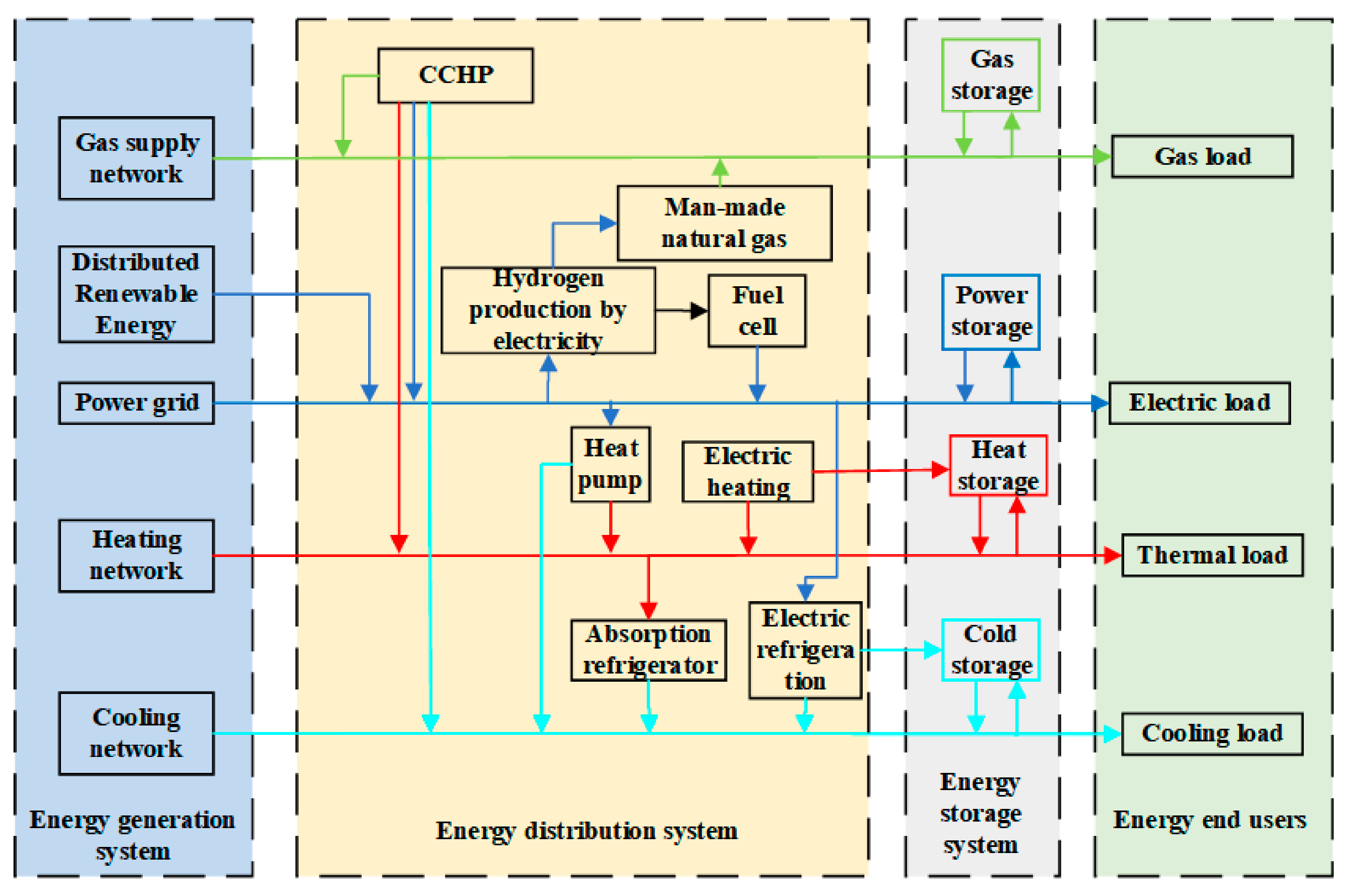
2. System Structure of Microgrid

A microgrid is an autonomous system composed of load, distributed generation and an energy storage system [30,31]. Mao et al. summarized the research contents of microgrid systems and presented the main Energy Interconnection System (EIS) projects and their classification in recent years [32]. The integrated energy system is located near the user side, involving cold/heat/electricity/gas multi-energy carriers, including micro source, load, energy storage and corresponding control, monitoring and protection devices and energy management systems. It is a single, controllable micro energy system that can realize the optimization of endogenous/network/load/storage in a region.
Modern systems have become increasingly complex [33,34,35,36,37,38], especially power supply systems [39]. At the basic physical structure and equipment level, all types of EIS are basically the same, generally covering integrated power supply, heating, cooling, gas supply, hydrogen supply and other energy systems as well as related communication and information infrastructure. A typical microgrid structure is shown in Figure 1.
As shown in Figure 1, the electric energy is coupled with the heat distribution and cooling network through the electric refrigerator and heating pump equipment; the heat distribution network transmits energy to the cooling network through the absorption refrigerator; simultaneously, the gas distribution network provides energy for other energy production equipment. The system contains a variety of energy equipment, which can be divided into coupling components and uncoupling components. Among them, the coupling elements include equipment that can realize the transformation of the energy form, which can realize the coupling between different subsystems, including CCHP, absorption refrigeration units, electric refrigeration units, etc.; the uncoupling elements include the production, use and storage of energy in a single system, including new energy power generation equipment, energy storage equipment and various types of loads. Each structure of the microgrid is introduced as follows:
(1)
Energy generation system: Without any energy conversion, it can realize the direct transmission of energy, such as through cables, overhead lines, pipelines, etc.
(2)
Energy distribution system: It can realize the transformation of the energy form or a change in energy grade. New energy power generation equipment such as wind turbines and photovoltaic (PV) equipment converts wind energy and solar energy, respectively, into electric energy; electric hydrogen generation equipment converts electric energy into hydrogen; fuel cells convert gas into electric energy; and special equipment such as heat pumps can absorb heat from a low-temperature heat source and release it to a high-temperature heat source through electric energy so as to realize a change in energy grade.
(3)
Energy storage system: Energy storage devices, including power storage, heat storage and cold storage equipment, can cut peaks and fill valleys and alleviate the problem of mismatch between gas turbine and cooling/heating loads.
(4)
Energy end users: The end users of energy, including industrial, residential, commercial and other users, who receive energy for power, refrigeration, heating and other purposes.

2.1. Energy Generation System

Power generation systems include PV power generation, wind power generation, diesel generators and batteries. In the dispatch period, the incentive demand response direct control method is used to transfer the load and compensate.

2.1.1. PV Power Generation

PV output is mainly different for two conditions: clear sky and non-clear sky. Under clear sky conditions, the output of PV power generators shows strong regularity, while under non-clear sky conditions, the output characteristics of PV power generators are relatively complex. The output power of a PV power generation system is related to the external temperature Tamb and illumination R, and the relationship is as follows [40]:
P P V = P P V , S T C × R R S T C × 1 λ × T a T r
T a = T a m b + R R S T C × T N O C 20
In Equations (1) and (2), P P V , S T C is the maximum power under standard test conditions; R S T C is the illumination value under standard test conditions; λ is a coefficient; T r , T a and T N O C are the reference temperature of the PV unit, the actual temperature of the PV unit and the temperature of the PV unit under normal operation conditions, respectively.

2.1.2. Wind Power Generation

Wind energy is a widely distributed renewable energy, and the continuous progress of technology has continuously reduced the cost of wind energy [41,42,43]. For wind turbines, the equation for wind energy conversion to fan power output is as follows:
P W = 1 2 ρ π R 2 V 3 C p
In this formula, ρ is the air density; R is the radius of the fan blade; V is the wind speed from the blade tip; C p is the wind energy conversion efficiency, which is a function of the blade tip speed ratio λ and the blade pitch angle θ , as
C p = f θ , λ
In this formula, the blade tip speed ratio λ is defined as
λ = W W R V
where W w is the mechanical angular velocity of the fan (rad/s).

2.1.3. Diesel Generator

The fuel consumption of a diesel generator is a linear function of its output power, which is
F = F 0 × Y g e n + F 1 × P g e n
In this formula, F is the fuel consumption rate; F 0 is the intercept coefficient; F 1 is the slope; Y g e n is the rated power of diesel generator; P g e n is the actual output power.
The operating power constraints of a diesel generator are
L min P g e n Y g e n 1
where L min is the minimum load rate of the diesel engine.
Moreover, the carbon emission C O 2 P d produced by a diesel generator can be expressed as follows [44]:
C O 2 P d = a + b × P d + c × P d 2
where a , b and c are carbon emission coefficients of diesel, and their values are 28.1444, 1.728 and 0.0017 (evaluated from practice), respectively [40].

2.1.4. Battery

For a single lead–acid battery with a capacity of C b and a rated voltage of U b , assuming that the maximum allowable discharge depth is D and the discharge efficiency is μ b , the electric energy that the battery can provide for each charge and discharge is
E b = C b U b D μ b × 10 3
Generally, the working voltage of the battery is stable and the working current is controlled at approximately 0.1 CA, so the output power of the battery is
P b = C b U b × 10 4

2.2. Energy Distribution System

An energy distribution system is used to distribute energy. It includes a bus bar and at least one branch for supplying a consumer load, in which the bus bar is designed as a flat/ribbon cable with a number of cores arranged next to one another for power and data transmission. The branch is integrated as a communication-enabling consumer branch into housing, which contains consumer-specific functionalities and has a contact device operating according to the principal of penetration technology.
A typical energy distribution system is the combined CCHP system, which can meet the needs of power, cooling and heating; improve energy efficiency; and reduce carbon emissions, which is an important way to solve the energy and environmental crisis [45]. At the same time, as a multi-generation total energy system, the CCHP system has a large number of components, and its operating conditions are complex and changeable, which makes it difficult to optimize.
The CCHP system involves a wide range of technologies and components and is usually composed of a power generator unit (PGU), a heat recovery unit, an absorption chiller (AC) and an auxiliary boiler. In this study, a solar PV array and electric water chiller are added to the traditional CCHP system structure. The structure of a CCHP system is shown in Figure 2.
The research on CCHP system optimization focuses on operation strategy optimization. The aim is to calculate the optimal operation mode and obtain the optimal integration performance of a CCHP system. Mago and Chamra proposed a hybrid optimization strategy based on “FEL” and “FTL” [46]. Zhao et al. proposed a multi-objective optimization model considering the energy, economy and environment of a CCHP system and solved the Pareto optimal solution set using a niche particle swarm optimization (PSO) algorithm [47].

2.3. Energy Storage System

Due to the intermittence and randomness of renewable energy and the continuous change in load, the configuration of energy storage equipment with a certain capacity in a microgrid can play an important role in stabilizing load fluctuations, improving power quality and maintaining system reliability by flexibly and rapidly adjusting the throughput of active/reactive power. The existing energy storage media can be divided into energy-type media and power-type media. The former include lead–acid batteries, lithium batteries and sodium sulphur batteries, with high energy density, low power density, few cycles and slow response speed; the latter include supercapacitors, superconducting magnetic energy storage and flywheel energy storage, with high power density, low energy density, many cycles and fast response speed. A single energy storage medium cannot meet the needs of all applications; therefore, the current research is focused on a hybrid energy storage system (HESS) composed of multiple energy storage media.
Tian et al. proposed a modeling and operation time scheduling method for MEMS with energy storage [48]. A steady-state multi-carrier energy flow is adopted, including the dynamics of heat transfer and thermoelasticity. The results show that the effects of heat transfer and thermal inertia are similar to those of energy storage and are defined as being comparable to the storage of energy. The model was built using a weighted directed cyclic graph and energy storage state transfer function. The system model was applied to the optimal scheduling problem as a problem based on PWL approximation and convex relaxation. The results showed that the model and method are reasonable for a meaningful MEMS system and provide an effective method for analyzing energy consumption.
Lv et al. put forward the method of using heat storage to improve the regulation capacity of cogeneration units in a large power grid [49]. Xu et al. used the heat storage capacity of cogeneration units to realize the absorption of excess energy from wind power generators [50]. The above solutions are no longer limited to the power system as they are based on the perspective of the Energy Internet, which considers the new energy consumption of microgrids from the direction of the comprehensive utilization of electricity, heat and other energy forms.
Energy storage materials are also a key factor in energy storage. As a new energy storage medium, phase change materials (PCMs) have received extensive attention in the field of building and materials [51]. This kind of material is cheap and easy to prepare and maintain on a large scale, so the service life is comparatively longer. PCMs can be used to provide energy density and chemical energy storage in the same order of magnitude, with economic advantages. Through the composition of a variety of materials, the phase change point is designed close to the comfortable temperature of the human body, which can achieve air conditioning-level cold storage and heat storage functions; it is integrated with the building on the energy consumption side, without a loss in the transmission process.
In the microgrid integrated energy system, energy storage equipment is used as a time conversion device to improve the efficiency and economy of the integrated energy system. Energy storage can be divided into electricity storage, heat storage, cold storage and gas storage. The characteristics of energy storage and release are characterized by three metrics: storage capacity, self-loss rate and energy storage efficiency. The change in the energy storage state of energy storage equipment is determined by the following formula:
S t i = S t 1 i 1 σ i + η c h a i P c h a , t i I c h a , i i P d i s , t i I d i s , t i η d i s i Δ t
where S is the state-of-charge (SOC) of energy storage equipment; P is the power of energy storage and discharge; I is the state of energy storage and discharge; Δ t is the length of a unit of time; subscript t is the time period; the superscript t is the type of equipment, in which c , h , e and g are used for cold, hot, electric and gas, respectively, or only the equipment number is employed; the energy storage status is marked with c h a and d i s in subscript; η c h a and η d i s are the energy storage efficiency of the energy storage equipment; σ is the energy storage loss rate.

2.4. Energy End Users

In the field of user-side microgrids, most studies have focused on operation planning, energy management, control protection and other related microgrid technologies. Power grid operation control is the key to ensuring the stability of users’ power supply and solving other microgrid problems [52]. In user-side microgrids, most of the distributed generation needs to be connected through the power electronic component interface, and the stable operation of the microgrid depends on the corresponding control strategy. Therefore, reasonable selection of the overall control strategy and optimization of the operation of the user-side microgrid are the basis of improving the distributed generation efficiency, the system stability and the users’ power supply reliability. At present, the common operation control methods for user-side microgrids mainly include master–slave control, peer-to-peer control and hierarchical control [53].
When a user-side microgrid with master–slave control operates in island mode, it usually has one or more distributed generators with constant voltage and frequency control as the main control power to provide a voltage and frequency reference for other distributed generators in the microgrid. The other distributed generator, as a subordinate controller, uses constant power control to regulate its own operation. During grid-connected operation, the system voltage is supported by the large power grid, and all distributed generators, including the main control unit, adopt constant power control.
Peer-to-peer control means that all the distributed generators in a microgrid have equal status without principal and subordinate control. In a microgrid with peer-to-peer control, the access to or removal of one distributed generator does not affect the control strategy of other distributed generators, and it is easy to implement plug-and-play of distributed generation.
Hierarchical control is a control strategy that sends control instructions to each part of the microgrid through a central controller, and each part runs autonomously according to the dispatch instructions. Hierarchical control can adopt a two-layer control structure or a three-layer control structure.

3. Optimization Framework

In general, there are some optimization objectives: energy performance, economic performance, environmental protection and other objectives. Their contributions and relative studies are summarized as Table 1.

3.1. Optimization Objective

3.1.1. Single Objective

At present, the research on microgrid optimization mainly simplifies multiple objectives such as operation cost reduction, energy management and environmental protection into a single objective for optimization, but there are often conflicts between multiple objectives, thus making it difficult to achieve the optimization at the same time. The following are the basic single objectives.
(1)
Energy performance
The research on single-objective optimization of microgrids mainly focuses on energy management optimization. For example, Kong et al. proposed a basic linear programming model to determine the optimal energy combination of a CCHP system with a gas turbine [54]. Sharkh et al. proposed a cost-based optimization problem referring to a short-term scheduling scheme for multiple parallel grid-connected fuel cell power plants (FCPPs) [55].
(2)
Economic performance
In the aspect of economic optimization, Wang et al. established an economic optimization model of a CCHP micro network by using opportunity constrained programming theory so as to optimize the operation scheme of the system [56]. Wu et al. proposed a mixed integer programming method for micro power supply and energy storage to solve the economic scheduling problem of a CCHP microgrid [57]. Sashirekha et al. presented a flexible algorithm to solve the problem of economic scheduling of cogeneration [58]. Aiming at the energy management of a microgrid under grid connected mode, Su et al. studied a power calculation model of energy management based on the charged state of electrical vehicle (EV) batteries [59]. They provided an energy management strategy considering PV output, electric vehicle charge and discharge power rate, power period division and energy storage state. Zhou et al. thought that the user side of a microgrid provides great potential for improving energy efficiency [60]. From the perspective of power supply chain management, an optimization model using time pricing for the user-side microgrid is proposed. The purpose of this model is to minimize the total cost of the power supply chain and optimize the charging and discharging behavior of the end users. Sechilarium et al. proposed a monitoring design for the optimization and prediction of power capacity in a DC microgrid based on the PV power supply, energy storage, grid connection and DC load in the microgrid [61].
From the perspective of optimal economic dispatch, an objective function can be established with the lowest operation cost of a microgrid. It is assumed that the generation power of a distributed generation unit in one unit of time, the load demand, the exchange power between the microgrid and main grid and the interactive electricity price are constant [62]. The cost is mainly composed of the maintenance cost for operating the renewable power generation unit, the cost of electricity price transaction with a large power grid and the replacement cost of the storage battery, as follows:
min   F 1 = i = 1 24 K O M × P p v i + K O M × P W T i + i = 1 24 ( F b u y F s e l l ) + F b a t
F b u y = f P b u y i
F s e l l = h P s e l l i
F b a t = S q n
where min F 1 is the lowest cost of system operation; K O M is the operation and maintenance coefficient of a renewable power generation unit; P p v i is the active power output of a PV cell in the first hour; P W T i is the active power output of a wind turbine in the first hour; F b u y is the electricity price paid by the large grid in the first hour; F s e l l is the selling price of the i-hour power grid; f is the coefficient of the purchase price; h is the power selling coefficient; P b u y i is the power purchased from the large grid in the ith hour; P s e l l i is the power sold by the micro network to the large grid in the first hour; F b a t is the cost of resetting the battery; S is the purchase cost of the battery; q is the full charge and discharge time in a day; n is the number of full charging and discharging cycles in the battery life.
According to the analysis of the microgrid operation cost function, the operation and maintenance cost of a renewable power generation unit (PV and wind turbine), as a non-schedulable unit, is fixed. Therefore, in order to calculate the minimal operation cost of the objective function microgrid, it is necessary to reasonably allocate the generation power of the dispatching energy storage unit (i.e., battery) and the exchange power between the microgrid and the large power grid so as to maximize the economic benefits.
(3)
Environmental protection
In the research on environmental protection, as an organic part of a smart grid, a microgrid has the characteristics of compatibility, flexibility, economy and autonomy. It can flexibly and efficiently use distributed generation and energy storage equipment, maximize the advantages of distributed generation, give full play to its environmental benefits and achieve the goals of energy conservation and emission reduction [63]. Yuan et al. proposed two energy management modes of a microgrid and analyzed the unit investment cost of energy conservation and emission reduction under the different management modes by taking an actual microgrid system as an example [64].
In terms of reducing carbon emissions, an objective function was established with the most cost-effective investment of energy saving and emission reduction for the microgrid operator, as follows [65]:
F = C I + C O P M E O E M
where C I is the total construction cost of the microgrid; C O is the total operation and maintenance cost of the microgrid; P M is the total income of the microgrid; E O is the CO2 emission generated by the power generation side when thermal power is used to meet the load demand of the grid; E M is the CO2 emission generated by the power generation side after the microgrid is added. The total CO2 emissions can be calculated as follows:
E C O 2 = E F C O 2 E E
where E C O 2 is the total CO2 emissions; E E is the total power generation; E F C O 2 is the carbon emission factor and the unit is kg/kW/H.
By analyzing the objective function of microgrid emission reduction, the optimal capacity ratio of distributed generation in the microgrid is calculated to reduce the wasting of resources and realize the energy saving and emission reduction benefits of the microgrid.

3.1.2. Multi-Objective

Generally, a multi-objective model can more accurately reflect the actual operation state of a microgrid than a single-objective model can, and it can achieve better environmental benefits with as little operation cost as possible [66]. Multi-objective optimization often takes into account the environment, economic benefits, system balance and other aspects.
(1)
The weighting factor method
Cheng et al. [67] proposed a CCHP-MG multi-timescale optimal scheduling model with ice storage air conditioning, which can not only meet the needs of users for cold, hot and electric energy but also effectively suppresses the random fluctuations of the supply and demand sides during the day so as to realize the economic and stable operation of the CCHP-MG. Li et al. proposed a distribution network energy storage configuration optimization method based on an improved multi-objective PSO algorithm and used the TOPSIS method to screen the optimal access scheme [68]. The feasibility and superiority of this method were verified by simulation. Hou et al. proposed an optimal scheduling method for electro thermal hydrogen multi-element energy storage (MES), established a multi-objective optimal scheduling model for energy storage and achieved the unified effect of economy, efficiency and stability [69]. Jiang et al. established a multi-objective optimization model of microgrid-controllable load based on the working characteristics of an air conditioner and water heater [70]. On this basis, a multi-objective controllable load optimization strategy was proposed, and its effect in an actual microgrid was simulated and analyzed by using a multi-objective, non-dominated sorting genetic algorithm.
For the optimization of an energy consumption subsystem, Wang et al. proposed a new distributed P2P energy trading method based on a double auction market, which can not only improve economic efficiency, energy self-sufficiency and renewable energy consumption, but also does not sacrifice privacy protection and robustness [71]. Amin et al. proposed a multi-energy demand response model, which provides more choices for multi-energy end users in an energy management strategy [72]. Jin et al. designed a dynamic pricing scheme to optimize the cost design and resource management of a microgrid system so as to reduce carbon dioxide emissions while maintaining profits [73]. González et al. proposed a demand response (DR) framework to optimize the microgrid of a distributed generation business park, aiming at improving system balance, integrating renewable energy, improving system operation efficiency and reducing carbon dioxide emissions [74].
(2)
Pareto multi-objective optimization
Multi-objective optimization has some concepts used to judge the final effect of optimization methods. The two most commonly used concepts are the necessary condition and sufficient condition of multi-objective optimization. If a multi-objective optimization form provides a necessary condition, for a Pareto optimization point, it must be the solution of the multi-objective optimization form. If a multi-objective optimization form provides a sufficient condition, its solution is Pareto optimization, but a certain Pareto optimization point may not be obtained.
Ma et al. established a robust environmental economic scheduling model based on robust optimization, aiming at the multi-microgrid scheduling problem while considering its economy and environment, the power interaction between multiple microgrids and the uncertainty of renewable energy and load forecasting [75]. The Latin hypercube sampling method and the average effective objective function were used to transform the model, and a multi-objective bacterial colony chemotaxis algorithm was used to obtain Pareto optimal solutions of four scenarios.

3.2. Decision Variable

In the research of microgrid optimization, the optimization decision variables indicate the scheme and measures to optimize the objectives, which are made by decision makers.
Zhao et al. established a new multi-criteria decision-making model; constructed an evaluation index system including 18 sub-criteria from the perspectives of economy, power supply reliability and environmental protection; and calculated the sub-criteria weights combined with the subjective weights of best worst method (BWM) judgment and the target weights calculated using the entropy weighting method [76].
Gu et al. proposed several widely accepted evaluation methods and indicators for CCHP microgrid planning, including energy utilization factor (EUF), artificial thermal efficiency (ATE), fuel saving ratio (FESR) and exergy efficiency (exeff) [77]. A CCHP microgrid has great economic benefits, environmental benefits and energy efficiency. Reasonable planning should include the following: adapting to the daily and seasonal load characteristics of multiple loads, smoothing the fluctuations of renewable energy output power, multi-energy balancing and improving the overall system efficiency.
Based on the synergy of a decision analysis and optimization model, Kumar et al. proposed a comprehensive general method framework for designing reliable, robust and economic microgrid systems based on the local available resources of rural communities in developing countries, considering the different characteristics of society, economy, technology and the environment [78]. A decision analysis considering various standards (technology, society, economy and environment) was carried out to select appropriate alternative energy sources to design a microgrid considering multiple scenarios.

3.3. Constraints

In the research on microgrid optimization, the constraints are different for different optimization decisions. In order to improve the reliability of a distribution system, Pang et al. proposed a novel concept of designing and operating a flexible microgrid [79]. Compared with the current method, the proposed flexible microgrid boundary can be expanded or narrowed according to the level of power generation and demand, technical constraints and customer comfort. Khalid et al. proposed an optimization model for microgrid scheduling and operation that can achieve a large number of constraints, such as power exchange with generation units, power balance with the main grid, etc. [80]. In order to improve the robustness of optimal scheduling of a Concentrating Solar Power and Combined Heat and Power Microgrid (CSP-CHPMG) with light in uncertain environments, Peng et al. constructed a robust economic multi-objective optimal scheduling model for the CSP-CHPMG based on the constraints on the balance between electric power and thermal power as well as the output of the CSP power station [81].
From the perspective of economy or environmental protection, microgrid optimization research is often inseparable from the optimization of operation cost. Considering the minimum cost operation of a microgrid, the constraints mainly include power balance constraints, generation capacity constraints, transmission capacity constraints between a microgrid and a large grid, location constraints of the microgrid energy storage system, etc.

3.3.1. Power Balance Constraints

Considering the minimum operation cost of a microgrid, it is necessary to calculate the power balance [82]. The power balance constraints can be expressed as follows:
i = 1 N P g e n , j + P b u y t P s e l l t = P l o a d
where P g e n , j is the generating power of generating units (PV, fan and energy storage) in any period of time; P l o a d is the required power of load.

3.3.2. Generation Capacity Constraints

In order to operate stably and reliably, each distributed generation unit in a microgrid must meet its own generation output constraints. Generation output constraints can be expressed as follows:
P D G i min P D G i P D G i max , i = 1 , 2 , , N
where P D G i min and P D G i max are the minimum and maximum generating output of the ith generating unit, respectively.

3.3.3. Transmission Capacity Constraints between Microgrid and Large Grid

With the increasing construction of microgrids, the importance of cooperation between microgrids and large grids is increasingly prominent. The microgrid can operate in conjunction with large grids or operate independently when needed. Transmission capacity constraints can be expressed as follows:
P L i n e min P L i n e P L i n e max
where P L i n e min and P L i n e max are the minimum and maximum transmission capacities, respectively.

3.3.4. Location Constraints of Microgrid Energy Storage System

When selecting and optimizing the location and capacity of an energy storage system, the allowable range of voltage deviation and power balance of the system should be considered.
(1)
Allowable range of voltage deviation
V min V i k V max
where V min and V max are the lower limit and upper limit of node voltage, respectively; V i k is the voltage value of node i at the kth moment.
(2)
Energy storage unit power constraint
P s t o r e _ min P s t o r e P s t o r e _ max
where P s t o r e _ min is the minimum power of the energy storage unit; P s t o r e _ max is the maximum power of the energy storage unit.
(3)
Energy balance constraints of energy storage unit
0 T P s t o r e i d t = 0
(4)
Power constraint of system
P = i = 1 N b u s P l o a d , i j = 1 N D G P D G , j k = 1 N s t o r e P s t o r e , k
where P is the injected power of the grid; P l o a d , j is the load power of the first node; P D G , j is the output of the jth distributed generator; N D G is the number of connected DGs; P s t o r e , k is the output of the kth energy storage unit, and it is positive when the kth energy storage unit is selected to provide power.

4. Optimization Algorithms

Microgrid optimization is one of the most important and challenging goals in the research field. In order to reduce energy consumption and improve economy and reliability, many studies have been conducted to determine the optimal configuration of microgrids. Several studies in the literature show that the optimization of a microgrid can be solved by various algorithms. The most frequently used algorithm type is a genetic algorithm (GA) [83,84,85,86,87,88,89,90,91,92,93,94,95]. For example, aiming at selecting the optimal size of microgrid components, Li et al. developed a GA to find the minimum microgrid cost [86]. Considering the microgrid life-cycle cost, Bin et al. [83] established an optimization configuration model of a hybrid AC/DC microgrid and applied the elitist non-dominated sorting genetic algorithm (NSGA-II) to solve the model. Furthermore, many researchers also used simulated annealing (SA) to solve the problem [87,88,89,90,91,92,93,94]. Aiswariya et al. used an SA optimization tool to solve the optimization problem of battery scheduling for a residential microgrid [87]. The PSO algorithm is also a widely used algorithm [85,86,87,88,89,90,91,92,93,94,95,96,97,98,99,100]. Zhang et al. developed an efficient search algorithm combining the PSO algorithm and the SA algorithm to solve a novel operation optimization model for a stand-alone microgrid [95]. Moreover, due to the fuzzy environment, many decisions need to be made using fuzzy decision optimization [76,101,102,103,104]. For example, Zhao et al. proposed an integrated fuzzy-MCDM (multi-criteria decision making) model to assess a battery energy storage system (BESS) [76]. Considering the robustness of the microgrid, researchers have also used robust methods to improve the flexibility and adaptability of microgrids [105,106,107]. For instance, Ebrahimi presented a decision-driven, stochastic, adaptive–robust microgrid operation optimization model [105]. In addition, there are some other methods to solve the problem, such as grey wolf optimization (GWO), moth flame optimization, the ant colony optimization algorithm and the grey cumulative prospect theory [108,109,110,111], etc. For example, Sharmistha et al. used GWO, a recently developed optimization technique, to minimize the energy cost of a microgrid and better utilize renewable energy sources [108]. Wang et al. built an operation optimization model and optimized it using the moth flame optimization algorithm to obtain the minimum operation cost [109]. In order to select the optimum planning program, Zhao et al. proposed a novel MCDM model combining the best worst method, which is applicable and feasible in the process of evaluation and selection [110].
In general, there are some specific methods to solve optimization problems: GA and improved algorithm, SA, PSO, fuzzy algorithm, robust methods and other algorithms (GWO, moth flame optimization, etc.). Their features and relative studies are summarized as Table 2.
The applications of these algorithms in the operation optimization of microgrids are presented below.

4.1. Genetic Algorithms

As a kind of non-deterministic quasi-natural algorithm, GA provide an effective way to optimize complex systems. According to previous investigations, many researchers have used a GA to solve the optimization problem in the field of microgrids.
Considering the interests of multiple stakeholders, Zhao et al. proposed a dynamic economic dispatch model of a microgrid and used a variant of NSGA-II to deal with the model [85]. The model in their study considers the overall economic optimization of multi-objective and multi-interest groups within the microgrid and, finally, can help to improve the power marketing economy and intelligent service.

4.1.1. Dynamic Optimization Strategy of Microgrids

The microgrid system consisted of two renewable energy sources: PV power and wind power. The PV power generation Ps(t) and the output power of the wind turbine Pw can be shown as Equations (25) and (26).
P s ( t ) = ϕ ( V m ( β ) , I m ( β ) )
P w = 0 a v + b P r a t e v v i n o r v v o u t v i n < v v r a t e v r a t e < v < v o u t
The variable β in Equation (25) is the tilt angle. In Equation (26), the variable v is the wind speed; vin, vout and vrate are cut-in, cut-out and rated wind speeds, respectively; P r a t e represents the rated power of the wind turbine; a and b are constants.
The battery used is of great significance in improving the quality of a microgrid’s power supply. The SOC of the battery St is determined by Equation (27):
S t = S 0 + t = 1 T P c h a , t X t Δ t t = 1 T P d i s , t Υ t Δ t E b
Initiate the particles. Set the total where Pcha,t and Pdis,t imply the charging and discharging power of the battery in t periods; Xt and Yt are the charging and discharging power of the battery, respectively; T and Eb mean the total and the capacity of the battery, respectively.
In the study, Cw and Cv are the prices of wind power and PV power, respectively, after being sold. Cwn and Cvn represent the cost of wind power and PV power, and CS and Cb are the selling price and purchasing price of a microgrid. Then, the unit price of load power supply can be shown as follows:
C w = C w n C s + C b = C w n + ( C b C s )
C v = C v n C s + C b = C v n + ( C b C s )

4.1.2. Microgrid Economic Optimization Model and Objective Functions

The study considers users, power grids, renewable energy and batteries, and the objective of the study was to ensure that the interest of each subject could be guaranteed and to optimize the comprehensive interests. Thus, there were three total objective functions: (1) maximize the benefits of the grid; (2) minimize the cost of generating electricity from renewable sources; (3) minimize the average unit price of electricity purchased by users. The functions can be described as follows:
C 1 = max t = 1 T C b t max ( P G t , 0 )
C 2 = min t = 1 T C w × P w t + C v × P v t
C 3 = min 1 t = 1 T P L t t = 1 T C t
In Equation (30), C b t represents the cost of purchasing electricity in the period t, and the transmission quantity between the power grid and microgrid is represented as P G t . C r t in Equation (31) is the generation cost of renewable energy in the period t, and the outputs of the wind turbine and PV in period t are shown as P w t and P v t , respectively. In Formula (32), the power supply cost in period t is C t = C r t + C b u t + C s e t + C e c t .

4.1.3. Constraints

The constraints consist of power balance constraints, renewable energy power constraints and battery charge and discharge constraints, which can be shown as follows:
P G t = P L t P W t P V t P E t
where PE indicates the output power of the battery.
P w P w t P v P v t
S min t S t S max t
where S min t and S max t represent the upper and lower limits of the SOC in period t.
In addition, some constraints of the battery should be considered, such as the power of charge/discharge and the number of charges and discharges, etc.

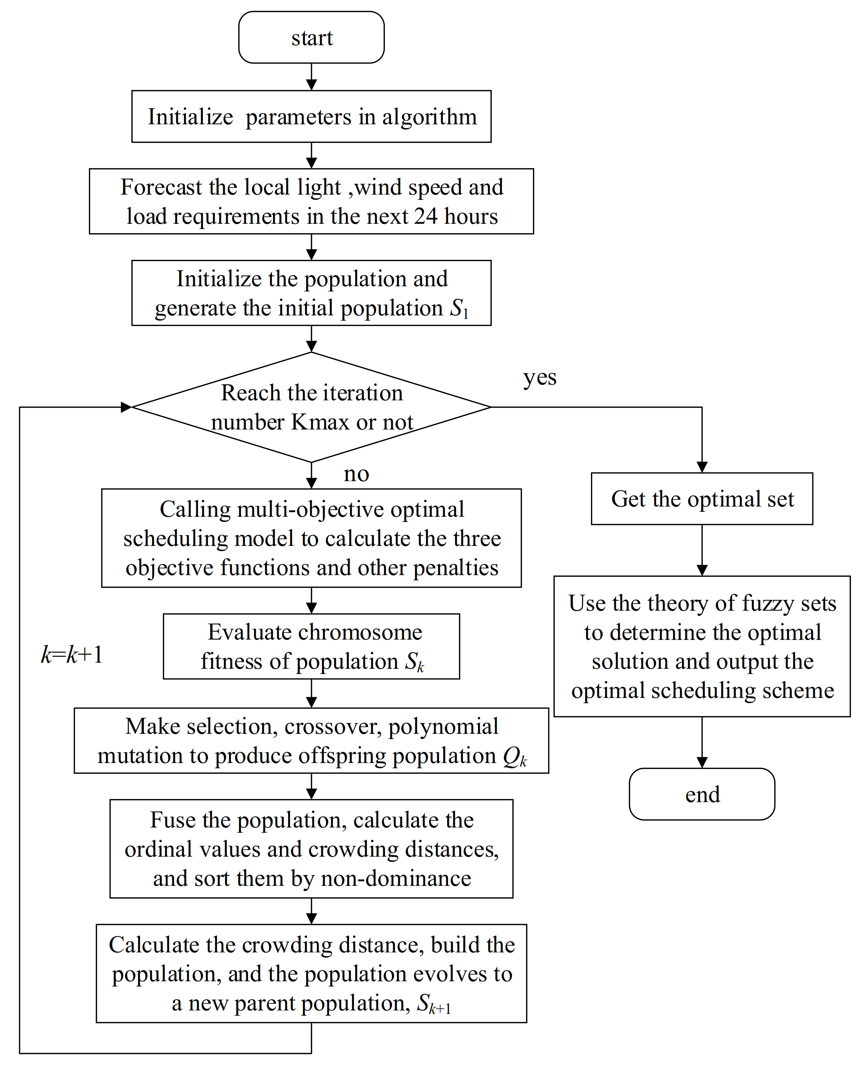
4.1.4. Model Solving

The study presented an improved multi-objective optimization algorithm based on NSGA-II. Different from traditional GAs, the algorithm adds the concepts of ordinal value, non-dominated sorting and crowding distance; carries out population evolution and, finally, obtains the optimal solution. Based on the three optimization objectives presented earlier, the study flow chart is shown in Figure 3.
In the flow chart, k is the iteration number; Kmax, S1, Sk and Qk are the maximum iteration number, the initial population, the population in the k-generation and the k-offspring-generation population, respectively.

4.2. Simulated Annealing

An SA algorithm is a random optimization algorithm based on a Monte Carlo iterative solution strategy. It is based on the similarity between the annealing process of solid matter in physics and the general combinatorial optimization problem. Due to the characteristics of the algorithm, a GA may not be able to obtain the optimal solution, but rather can only obtain an approximate optimal solution, while an SA algorithm can mitigate the shortcomings of the GA and obtain the best solution. Many researchers have used SA algorithms to find optimized solutions in the field of microgrids. For instance, in order to reduce energy consumption and further reduce the energy costs for power users, Aiswariya et al. used an SA optimization tool to optimize the battery scheduling for residential microgrid application [87].

4.2.1. Microgrid Battery Scheduling and Objective Functions

Unlike the study in Section 4.1, a BESS was also included in the microgrid system besides a PV system and a wind power system in this study. Two typical houses were considered as loads. It was assumed that the PV system capacity was 5 kWp and the maximum capacity of the wind power system was 15 kWp. In addition, it was considered to be connected with a battery system with a maximum energy capacity of 100 kWh and an inverter with a maximum power of 10 kW.
The goal of the study was to reduce the energy cost related to the microgrid by finding the optimized amount of energy to buy/sell from/to the grid. Assuming that the total time considered is 24 h, with 1 h intervals, the authors used an SA algorithm to solve the problem. To minimize the total cost, the objective function is formulated in Equation (36) as
min ( f 1 ) = i = 1 24 ( ( H 1 ( i ) + H 2 ( i ) P W ( i ) P S ( i ) + X ( i ) ) Δ t ) C ( i )
with the constraint of
P b max x ( i ) P b max E b min E b ( i ) E b max H 1 ( i ) + H 2 ( i ) + x ( i ) = P w ( i ) + P s ( i ) + G ( i )
In the equation, H 1 ( i ) and H 2 ( i ) represent the power demanded by the two homes, A and B, during interval “i”; P S ( i ) , P W ( i ) and X ( i ) represent the power being delivered by the PV system, wind power system and the battery during interval “i”, respectively; Δt is the time slot; C ( i ) represents the electricity tariff based on a flat rate and time-of-use pricing (ToUP) in the area of Australia’s capital.

4.2.2. Microgrid System Modeling

The power output of a PV panel PS is related to the size and efficiency of the panel. It can be shown as Equation (38).
P S = η S × A × 0.9 × S I × ( 1 + γ ( t 0 25 )
where η S is the overall efficiency of the PV panel; t 0 and γ represent the outdoor air temperature and temperature coefficient of the maximum power output, respectively. The wind power output P w is similar in Equation (26), depending on the rated power of the turbine and wind speed.
When the renewable power generation cannot meet the load demand, the battery energy storage is used to provide power; otherwise, the battery charges when there is excess power remaining.
Regarding the pricing scheme, the authors used a flat tariff structure and ToUP. In the pricing scheme, the total hours are divided into different periods with different prices, and these periods are usually divided into peak hours, off-peak hours and trough hours.

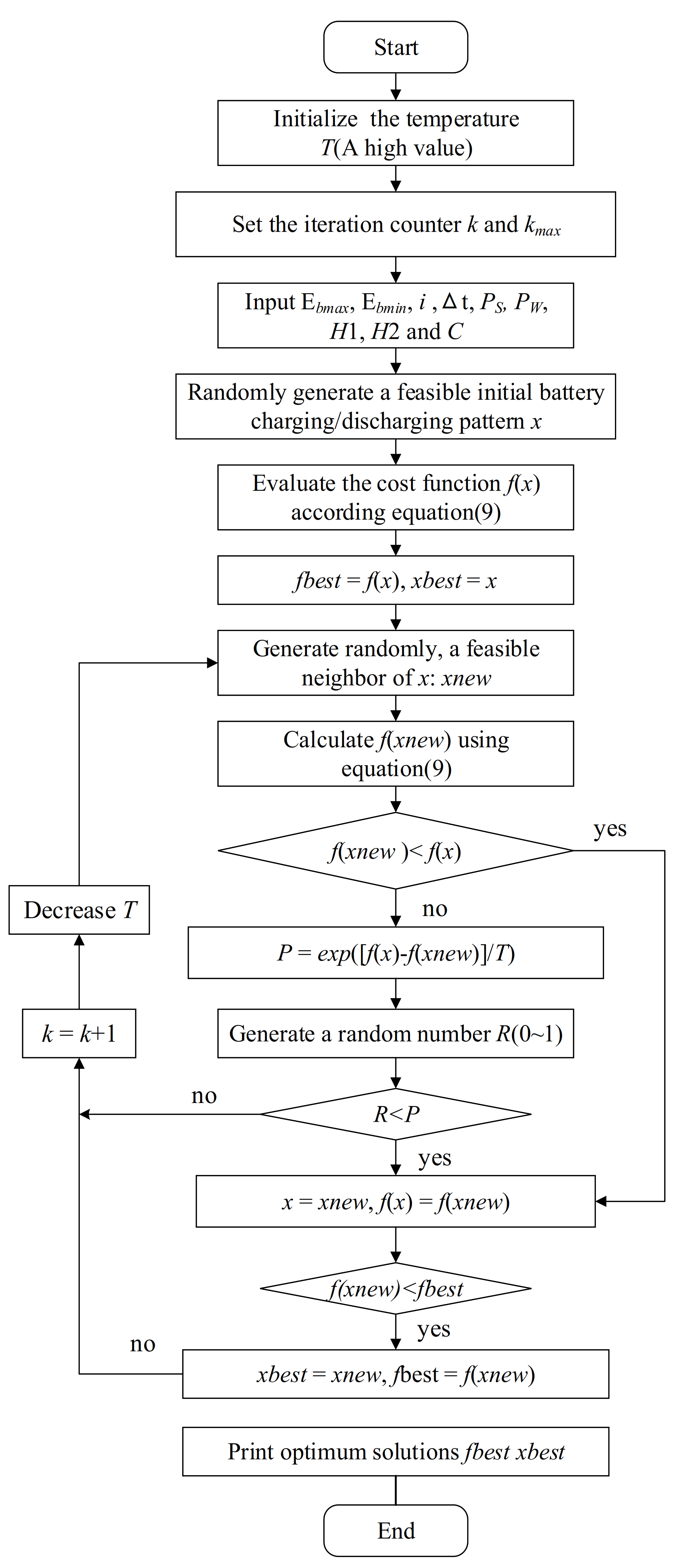
4.2.3. SA Algorithm for Battery Scheduling

The flow chart for the simulated algorithm in this study is shown in Figure 4.
In the chart, E b max and E b min denote the maximum energy of the battery and the minimum energy of the battery during interval “i”, respectively.

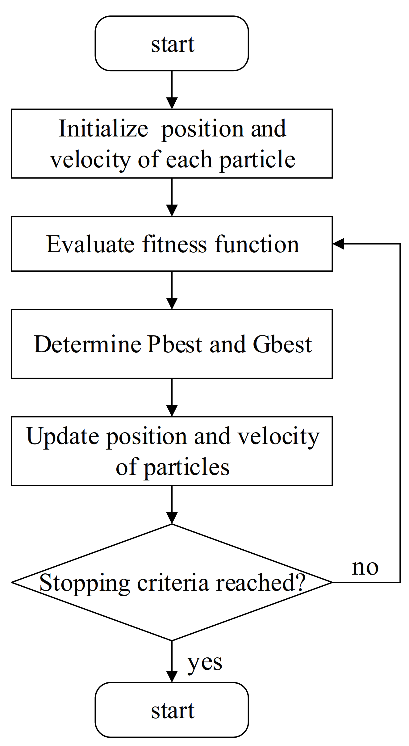
4.3. Particle Swarm Optimization

The PSO algorithm is a random searching algorithm based on group cooperation developed by simulating bird flock foraging. Similar to GAs, it is also an iterative optimization algorithm. PSO employs only a single simple velocity updating process and does not need to adjust many parameters. It is more easily executed compared to a GA. Thus, many studies have used PSO to solve the problem of microgrid optimization.
Karthikeyan et al. (2016) [100] proposed the concept of thermochemical storage (TCS) and an ice storage air conditioner to meet users’ heating and cooling demands under severe weather conditions. In smart TCS, the heat and fuel cell will be effectively stored. The objective of the study was to minimize the cost with the constraint of pollutant emissions.

4.3.1. Optimization Model

The microgrid consisted of a main grid that is connected through an inverter and converter to a DC microgrid. The loads were divided into three kinds: heating load, cooling load and other electrical loads. The power system consisted of a PV system, a wind turbine, a fuel cell, a microturbine, a diesel generator, TCS, an ice storage air conditioner and a battery storage. Of these, the PV cell and wind turbine are powered by nature, and the fuel cell, microturbine and diesel generator need fuel input. The fuel of the TCS comes from a collector and fuel cell. The ice storage air conditioner consumes only during valley periods of the main grid. The conditions of battery charging/discharging are the same as the situation described in Section 4.2. Instead of electric power, the TCS and ice storage air conditioner outputs are in the form of heat and cooling, respectively.

4.3.2. Objective Function

Considering the microgrid economic dispatch, the objective of the study was to meet the total demand with less emissions, reduce operation costs and satisfy the constraint related to the problem at the same time. Thus, there were three objectives in total: (1) minimize the total operation cost; (2) minimize the total emissions of pollutants; (3) ensure that the demand is met according to constraints.
(1)
Operation cost
If the demand of local consumers is not satisfied, then the main grid will supply the extra power. Therefore, a certain cost has to be paid to purchase the power. In addition, if the power generation in the microgrid is adequate, the power will be sold to the main grid. Then, the cost function can be shown as follows:
C F ( P ) = i = 1 N ( C i F i ( P i ) + O M i ( P i ) + D C P E i I P S E i )
where CF(P) indicates the operating costs, Ci is the fuel cost of generator i, OMi represents the operating and maintenance cost of the ith generating unit, DCPEi indicates the purchased electricity cost of the ith unit and IPSEi indicates the income of the microgrid from selling the extra power of the ith unit.
(2)
Emission level
To avoid ozone depletion, one objective is to minimize pollutant emissions. The total emission of pollutants is given by the following:
E ( P ) = i = 1 N 10 2 ( α i + β i P i + γ i P i 2 ) + ζ i exp ( λ i P i )
In the Equation (40), αi, βi, γi, ζi and λi are non-negative coefficients of the ith generator’s emission characteristic.
(3)
Thermochemical heat storage
In TCS, the heat energy is obtained from solar collectors. The TCS is based on thermally reversible reactions, the power delivered from which can be shown as follows:
p = c p A v ( T L T 0 ) = C P ρ A v ( T R T 0 ) 1 exp h S L / c p ρ A v
In Equation (41), h represents the heat transfer coefficient; L, S and A indicate the length, circumference and cross-section of the heat exchange tube, respectively; V is the flow speed of the heat transfer fluid; cp is the specific heat; TR indicates the uniform reactor temperature.
(4)
Ice storage air conditioner
The ice air conditioner has three different modes: (1) air conditioning mode; (2) ice making mode; (3) ice melting mode. Ice melting mode usually does not operate in valley periods. The performance models of the air conditioning mode and ice making mode can be shown as Formulas (42) and (43).
P c ( T ) = P g ( T ) 0.001226 P g ( T ) + 1.91
P c t m ( T ) = P m ( T ) 0.001226 P i m ( T ) + 1.91
In Equation (42), P c ( T ) and P g ( T ) denote the power consumption of the ice chiller and the cooling power generated from the ice chiller at time T, respectively.
In Equation (43), P c t m ( T ) represents the power consumption of the ice chiller at time T in the mode of ice making and P t m ( T ) is the cooling power at time T.
(5)
Battery storage
The SOC of a battery plays a vital role in the life cycle of the battery. To increase the life cycle of a battery, the constraint function can be formulated as follows:
S O C ( T + 1 ) = S O C ( T ) η b c I b c ( T ) + 1 η b d I b d ( T ) P b ( T ) Δ t / C b I b c ( T ) P c min + I b d ( T ) P d min P b ( T ) I b c ( T ) P c max + I b d ( T ) P d max I b c ( T ) + I b d ( T ) ( 0 , 1 ) S O C min S O C ( T + 1 ) S O C max
In Equation (44), ηbc and ηbd represent the charging and discharging efficiency of the battery, respectively; Ibc and Ibd indicate the charging and discharging current of the battery, respectively.

4.3.3. Modeling of PV and Wind Power Systems

A PV system can be influenced by various conditions, such as weather conditions and the temperature of the module. It is assumed that S s t c = 1000 W/m2 and T s t c = 25 °C. Generally, the current I from the PV array under the reference can be given as follows:
I = I s c 1 C 1 e V C 2 V O C 1 C 1 = 1 I m I S C e V m C 2 V O C C 2 = V m V O C 1 / In 1 I m I S C
In (45), Isc is the short-circuit current; V and Vm are the voltage at a given time and the voltage at Pmax, respectively; Im is the current at Pmax.
The wind power output P w is similar to those in Section 4.1 and Section 4.2, depending on the rated power of the turbine and wind speed. Additionally, the speed is determined by two parameters and its probability density function is shown as follows:
f ( v ) = k c v c k 1 e v c
where k and c are the shape parameter and the scale parameter, respectively; and v is the wind speed.

4.3.4. Particle Swarm Optimization

There are three steps required to execute PSO:
Step 1: Initiate the particles. Set the total number of particles in the process. The initial velocity of the particles is zero. The value of the initial particles is set as Pbesti and the best value with minimum fitness is stored as Gbest.
Step 2: Modification of velocity and position. For the next iteration t+1, the particles move randomly within the search range and append a new velocity to each of the new positions. Then, compute the fitness value f t t + 1 i of each particle.
Step 3: Revision of Pbest and Gbest values. Compare the value of f t t + 1 i and f t t i , then repeat and iterate or obtain the optimal value according to the compared results.
The flow chart of the algorithm is given in Figure 5.

4.4. Fuzzy Decision

Fuzzy decision making is a mathematical theory used under fuzzy environments. It can be used in a wide range of applications. Thus, many researchers also use the method of fuzzy decision making to optimize the configuration problem in microgrids. For example, Cao et al. proposed an improved, two-archive, many-objective, evolutionary algorithm (TA-MaEA) based on fuzzy decision making to solve the optimization problem for a hybrid microgrid system (HMS) [101]. The objective of the study was to reduce the cost, lower the probability of the loss of power supply and reduce pollutant emissions.

4.4.1. Objective Functions

Similar to the former study, the HMS consisted of wind turbines, a PV system and a diesel generator and the main grid. Here, the extra power will be stored in a battery when electricity is produced by the wind turbines and photovoltaics. If the power generated by the wind turbines and photovoltaics cannot meet the demand, the stored power will be utilized.
There were four objectives for optimization:
(1)
Costs
The operating costs include the costs of generating power from wind turbines and PV panels, the costs of battery charging/discharging, the costs of the diesel generator and the costs of the power exchange between the microgrid and the main grid. The total cost C can be given as follows:
C = t = 1 T ( C g ( t ) + C b ( t ) + P g ( t ) × c g + P f ( t ) × c f )
where c g and c f are the costs of the electricity purchased from the main grid and the electricity generation costs of the wind turbines and PV panels.
Particularly,
C g = A w × P w ( t ) × c w + A pv × P pv ( t ) × c pv
C b = P b _ dc ( t ) × c d c P b _ ch ( t ) × c ch
P g ( t ) = λ × ( P l o a d ( t ) P all ( t ) P b ( t ) )
P f ( t ) = 0.246 × P d g ( t ) + 0.08415 × P f _ r
In Equation (48), P w ( t ) and P v ( t ) represent the electricity output by wind turbines and PV panels per unit of time, respectively; c w and c pv indicate the electricity generation costs of wind turbines and PV panels. In Equation (49), P b _ dc ( t ) and P b _ ch ( t ) are the electricity discharged and charged by the battery per unit of time; c dc and c c h are the electricity generation cost of the diesel generator and the profit from providing additional power to the energy storage system. In Equation (50), P l o a d ( t ) indicates the electricity amount from load demand and P b ( t ) is the current electricity amount in the battery. In Equation (51), P f _ r represents the diesel generator’s rated power.
(2)
Reliability
The situation LPSP can be defined as a situation in which the amount of electricity produced and purchased cannot satisfy the demand, which can be shown as follows:
LPSP = t = 1 T ( P load ( t ) P a l l ( t ) + P b _ min + P d g ( t ) t = 1 T P load ( t )
In the above equation, P b _ min represents the minimum permitted electricity remaining in the battery.
(3)
Pollutant emissions
The pollutant emissions, PE, can be simulated by linking the emissions to the amount of electricity generated by the generator set. The function can be given as follows:
P E = α + β × t = 1 T P d g ( t ) + γ × t = 1 T P d g ( t ) 2
where α, β and γ represent the emission characteristics of the microgrid.
(4)
Power balance
When the microgrid is connected to the main grid, improving the self-production and self-sale capacity of the HMS in each is conducive to the effective operation of the system. The related function is given as follows:
P B = 1 T t = 1 T P a l l ( t ) P l o a d ( t ) ) 2

4.4.2. Constraints

According to the actual situation, the power supply should have a certain initial range. The output power of the wind turbines can be expressed as follows:
P w ( t ) = 0 , ϕ × V 3 ( t ) φ × P w _ r , P w _ r V ( t ) > V c u t _ o u t V c u t _ i n < V ( t ) < V r a t e d V r a t e d < V ( t ) < V c u t _ o u t
where V ( t ) indicates the wind speed in the current time interval and P w _ r is the standard wind power; V r a t e d is the rated wind speed; V c u t _ i n and V c u t _ o u t are the start speed and stop speed of the wind turbines, respectively.
The output power of the PV panels can be expressed as follows:
P pv ( t ) = P p v _ r × G ( t ) G ref 1 + K t ( T ( t ) + ( 0.0256 × G ( t ) ) ) T r e f
where P p v _ r represents the rated PV power and G ( t ) is the horizontal irradiance. T(t) indicates the ambient temperature. In addition, G ref = 1 kW/m2 and K t = 3.7 × 10 3 .
The battery status can be given as follows:
P b _ c h ( t ) = P all ( t ) P load ( t )
P b _ dc ( t ) = ( P l o a d ( t ) P a l l ( t ) ) ( P b ( t ) P b _ min )
Additionally, the function of battery exchange can be formulated as follows:
P b ( t + 1 ) = ( P b ( t ) + P b _ c h ( t ) ) ( P b ( t ) P b _ d c ( t ) )
Finally, the loading area of the wind power system and PV panels and the storage capacity of the battery should be within a certain range, which can be shown as follows:
A w _ min < A w < A w _ max
A pv _ min < A pv < A pv _ max
p b _ min < P b ( t ) < P b _ cap < P b _ max

4.4.3. Fuzzy Decision-Making Method

Considering the choice of solutions, the authors proposed an adaptive fuzzy decision-making method. The Pareto solution can be given as follows:
X i j = X 11 X 12 X 1 M X 21 X 22 X 2 M X N 1 X N 2 X N M
Step 1: Normalize X i j before performing the operation by using the principle of minimum fuzzy membership. Then, the degree of membership of the ith decision variable to the jth objective rij can be obtained, which can be shown as follows:
r i j = 1 X i j min X i max X i X i j max X i min X i min X i X i j max X i 0 X i j > max X i
Step 2: Define the superior decision variables gi and inferior decision variables bi.
Step 3: Normalize the mean of each objective value to obtain the weight vector. The weight vector for each objective is given as follows:
W i = j = 1 N f i ( x j ) N
w i = W i i = 1 M W i
Step 4: The superior/inferior decision-making distance, which is the distance between a decision-making result rj and a superior/inferior decision-making result, can be obtained as follows:
d j c = i = 1 M w i ( g i r i j ) 2
d j b = i = 1 M w i ( r i j b i ) 2
Step 5: Obtain the distance weights between a decision variable and each superior/inferior decision variable as follows:
D j c = μ j d j c
D j b = ( 1 μ j ) d j b
Step 6: Obtain the degree of membership of each solution. The function is given as follows:
min F ( μ j ) = min D j c 2 + D j b 2
Step 7: The electric solution for the decision maker can be obtained as follows:
μ j = d j b 2 d j b 2 + d j c 2

4.5. Robust Method

Optimizing the robustness of microgrids can increase the flexibility and independence of power generation and reduce the occurrence of natural disasters. Hence, robust optimization of microgrid planning plays a very important role in the field of microgrids and some studies have been conducted on this topic.
To reduce the variability among scenario costs caused by uncertainties, Yu et al. developed a multi-objective optimization model for robust microgrid planning, which is based on an economic robustness measure [107]. The objective of the study was to reduce the cost and lower the pollutant emissions.

4.5.1. Robust Economic Optimization Model for Microgrid Planning

The proposed model in Nans’ study consists of an internal combustion engine (ICE), fuel cell, a gas turbine and a gas engine. These technologies are distributed energy resources (DERs), which can provide power and heat locally with fuel resources. Most of the DERs are renewable energy resources with distributed energy storages (DESs). Additionally, wind turbines and PV panels are also included in the study.
The multi-objective function based on robust optimization is given as follows:
f = u E × L + u W C × ( 1 L ) 0 L 1
where u E = s p s c s , and u W C c s .

4.5.2. Constraints

(1)
Economic balance
The overall annual cost of different scenarios is the sum of the annual investment cost, operation and maintenance cost, fuel cost, carbon tax and power cost from the utility grid, subtracting the revenue from selling power. The overall cost cs can be formulated as follows:
c s = c i n v s + c o m s + c f u e l s + c c t a x s + c b u y n s r s a l s
where cinvs, coms, cfuels, cbuyns, rsals and cctaxs represent the capital cost, the maintenance cost, the fuel cost, the cost when purchasing power from the utility grid, the revenue when the microgrid sells excess power to the utility grid and the tax caused by the excess carbon emission, respectively.
The parts of the polynomial (74) can be given as Equations (75)–(80):
c i n v s = i c a p i F C i I r / 1 1 / 1 + I r L T i + q c a p q F C S q I r / 1 1 / 1 + I r Q T q
c o m s = i c a p i O M F i + i , m a l l o t i , m , s O M V i
c f u e l s = i , m , f f d e r i , f , m , s + f b o i f , m , s F P f , s
c b u y n s = m e b u y n m , s E P m , s
r s a l s = i , m e s a l i , m , s S P s
c c t a x s = ( d m s C L I M ) C T A X s d m s C L I M 0 d m s C L I M
(2)
Load balance
The overall power load should be subjected to DERs, batteries and the utility grid, which can be formulated as follows:
E L m , s T i e d e r i , m , s + d i s c b a t t , m , s i s a v e i , b a t t , m , s + e b u y n m , s i e s a l i , m , s
E L m , s T φ s i e d e r i , m , s + d i s c b a t t , m , s i s a v e i , b a t t , m , s
H L m , s T i h d e r i , m , s + d i s c t h e r m o , m , s i s a v e i , t h e r m o , m , s + h b o i m , s
H L m , s T φ s i h d e r i , m , s + d i s c t h e r m o , m , s i s a v e i , t h e r m o , m , s
Equation (82) indicates that the power generation of the microgrid should meet at least a fraction, φs. Equations (83) and (84) indicate the demand and supply balance of heat, respectively.
(3)
Energy allocation for DER
The overall power allocated by the DER consists of three parts: (1) the power utilized for satisfying the load; (2) the excess power stored in the batteries and (3) the excess power sold to the utility grid. Then, the function can be given as follows:
a l l o t i , m , s = e d e r i , m , s + s a v e i , b a t t , m , s + e a s l i , m , s
Then, the constraint is shown as follows:
η E L m , s T y i , m , s a l l o t i , m , s y i , m , s A
The constraint of wind turbines and PV panels is similar to that in the former studies, mainly being subjected to the speed of the wind and the area of the solar panels, irradiation, etc.
Due to the budget and other regulations, the installation capacity of each DER can be subjected to the following equation:
a l l o t i , m , s / T c a p i M A X E i
(4)
Energy storage constraints
The discharged energy can be formulated as Equation (88) when a DES is selected to store the power or heat.
d i s c q , m , s = ε q l o s e q , m , s
The DES inventory balance is represented on a monthly basis, and it can be calculated by the following:
s t o r e q , m , s = 1 / 2 c a p s q T ζ s t o r e q , m 1 , s + i s a v e i , q , m 1 , s i d i s c q , m 1 , s m J a n m J a n
It is assumed that January is the starting time point with half of the storage capacity. The objective is to estimate the rough design specification. Hence, the capacity of the DES is represented on a monthly basis.
The constraint of the total discharged energy can be shown as follows:
l o s e q , m , s s t o r e q , m , s c a p s q T M A X S q
where s t o r e q , m , s is the DES inventory and c a p s q is the monthly capacity of the DES. M A X S q represents the designed upper bound.
y s a v e s q , m , s + y d i s c q , m , s 1
y s a v e q , m , s M I N S q i s a v e i , q , m , s y s v e q , m , s M A X S q
y d i s c q , m , s M I N S q d i s c i , q , m , s y d i s c q , m , s M A X S q
The bounds of stored and discharged energy are given as Equations (92) and (93), respectively.

4.6. Other Algorithms

In addition to the algorithms mentioned before, other algorithms for resource optimization of microgrids have also been used in some studies, such as GWO, moth flame algorithm, ant colony algorithm, etc. These algorithms also have their own advantages in the resource optimization problem.
For example, GWO is a meta-heuristic algorithm proposed by Mirjaili [112,113]. Compared with other algorithms, GWO has the advantages of solution accuracy, small computation and aversion of premature convergence. GWO can also be used to optimize energy management in microgrids. Kutaiba et al. mentioned that BESSs have become an integral feature of the microgrid owing to their intermittency and wide range of dynamics [102]. Thus, to ensure the optimal use of the renewable sources and to reduce conventional fuel utilization in intelligent energy management, the authors proposed an approach to meet the requirements in microgrids using the GWO technique.

4.6.1. Objective Function

The objective of the study was to reduce the total cost while satisfying all the constraints. Therefore, the total cost function of the generation sources can be determined as follows:
M i n F ( X ) = t = 1 T f t + O M D G + T C P D B E S b
where
f t = t = 1 T C o s t g r i d , t + C o s t D G , t + C o s t B E S , t + S U C M T , t + S U C F C , t + S D C M T , t + S D C F C , t
Additionally, each part of the polynomial can be given as follows:
C o s t g r i d , t = B g r i d , t P g r i d , t ( 1 t a x ) B g r i d , t P g r i d , t 0 P g r i d , t > 0 P g r i d , t < 0 P g r i d , t = 0
C o s t D G , t = B M T , t P M T , t μ M T , t + B F C , t P F C , t μ F C , t
C o s t B E S , t = B B E S , t P B E S , t μ B E S , t
S U C M T , t = S U M T × max ( 0 , μ M T , t μ M T , t 1 )
S U C F C , t = S U F C × max ( 0 , μ F C , t μ F C , t 1 )
S D C M T , t = S D M T × max ( 0 , μ M T , t 1 μ M T , t )
S D C F C , t = S D F C × max ( 0 , μ F C , t 1 μ F C , t )
O M D G = ( O M M T + O M F C + O M P V + O M W T ) × T
The total operation dispatch cost of the microgrid consists of the dispatch cost from the utility grid, the costs of fuel cell distributed generators (DGs), the cost of the battery energy storage (BES) operation, the operation and maintenance costs of the DGs, the costs of start-up and shut-down of micro-turbines and fuel cells and the total cost of BES each day. Then, the storage cost can be calculated as follows:
C o s t B E S = ( F C B E S + M C B E S ) × C B E S , max

4.6.2. Constraints

The operational cost is subject to the balance of the electrical load demand, the boundaries of DG constraints, the grid constraints, the operation reserve constraints and the BES constraints. The constraints are listed as the following equations:
P D , t = P _ M T , t u _ M T , t + P _ F C , t u _ F C , t + P _ P V , t + P _ W T , t + P _ B E S , t u _ B E S , t + P _ g r i d , t
P _ M T , min P _ M T , t P _ M T , max P _ F C , min P _ F C , t P _ F C , max P _ P V , min P _ P V , t P _ P V , max P _ W T , min P _ W T , t P _ W T , max t = 1 , , T
P g r i d , min P g r i d , t P g r i d , max t = 1 , , T
P _ M T , t u _ M T , t + P _ F C , t u _ F C , t + P _ P V , t + P _ W T , t + P _ B E S , t u _ B E S , t + P _ g r i d , t P D , t + O R t
The battery constraints can be classified into charging and discharging modes. The boundary limits of the BES power in discharging/charging modes are shown as follows:
P B E S , min P B E S , t P B E S , max t = 1 , , T
Additionally, the maximum power and minimum power of a BESS are shown as follows:
P B E S , t max = max P B E S , max , ( C B E S , t C B E S , min ) Δ d Δ t t = 1 , , T
P B E S , t min = min P B E S , max , ( C B E S , t C B E S , min ) Δ d Δ t t = 1 , , T

4.6.3. GWO Implementation for Microgrid Management Optimization

In the study, to minimize the operational cost of generation sources and fulfill the constraints mentioned above, the authors used GWO to solve the problem by finding the optimal values of the parameters. The flow chart of GWO can be seen in Figure 6.

5. Literature Bibliometric

Research on microgrid optimization has always been a hot topic. Using CiteSpace, this paper summarizes the literature published in journals indexed in the SCI related to microgrid optimization from 1 January 2014 to 28 March 2021. The keywords used for searching the papers were “operation optimization” and “microgrid”. We used the institution and country of the first author of a paper as the representative institution and country of that paper. The publication statistics are shown below.

5.1. Methods and Data

5.1.1. Methods

For analysis, the Java program CiteSpace, developed in 2006, which is a powerful tool for literature analysis and visualization in bibliometrics [114], was used. The software integrates many programs to achieve text mining, network pruning, clustering and naming and burstiness detection. The advantage of this software is that it can reflect the knowledge structure of the literature intuitively and clearly.

5.1.2. Data

Bibliographic data on microgrid optimization were collected from the Web of Science (WOS) covering a period of 7 years (2014−2021). There are 1394 records in WOS (excluding reviews).

5.2. Results

The number of articles and the total citations of microgrid optimization each year are shown in Figure 7.
A total of 1394 papers related to microgrid optimization have been published since 2014. The number of articles shows a large increase from 2014 to 2020, from 89 to 278. It can be seen from the number of citations that the influence of the journals has significantly increased, and scholars are paying more and more attention to the research of microgrid optimization, and the fastest growth was in 2017, with the growth rate of journal publications reaching 30.64%. Among them, the most cited article is “A Model Predictive Control Approach to Microgrid Operation Optimization”, with a total of 345 citations.

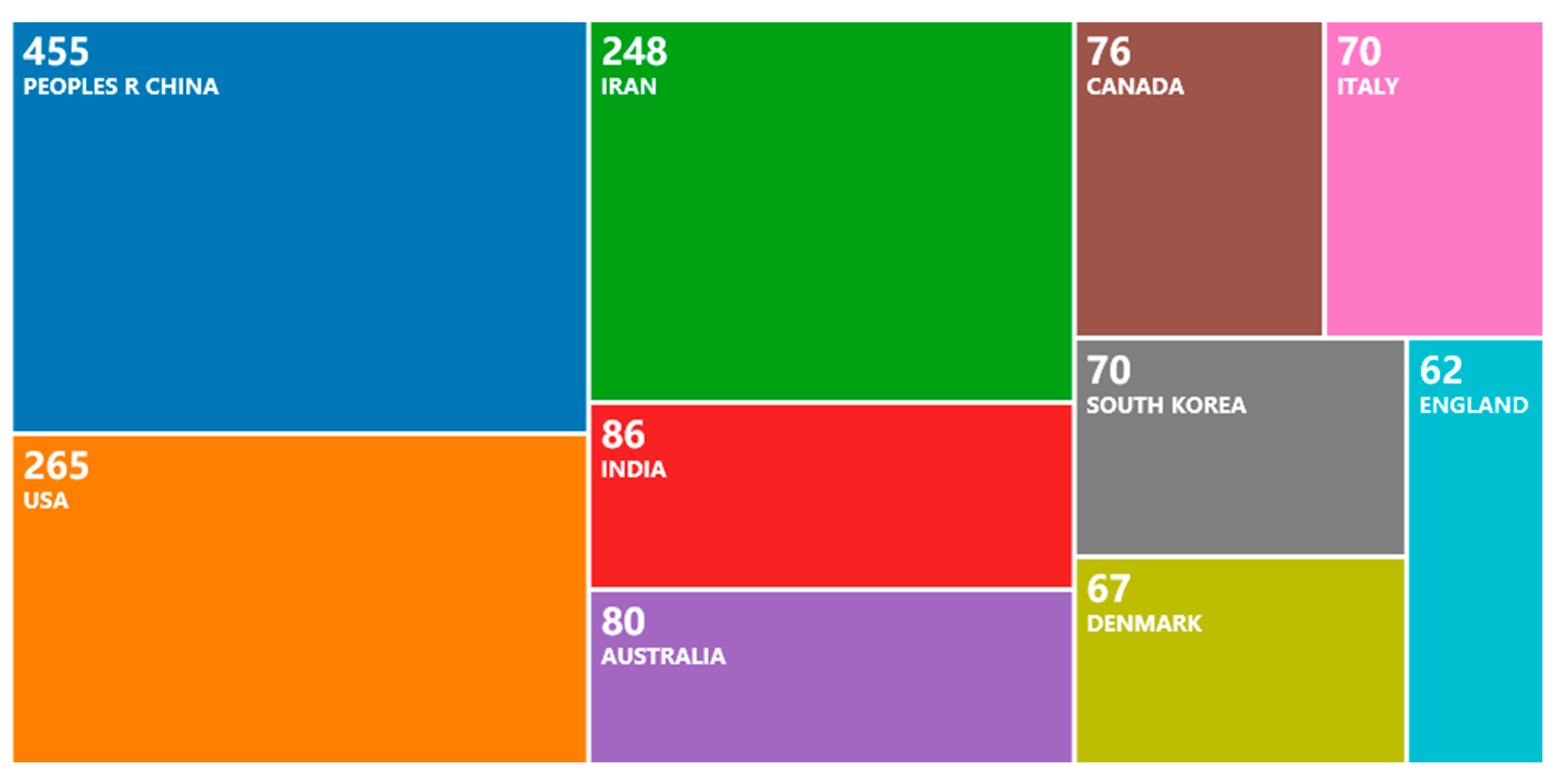
5.2.1. Country and Publisher

As shown in Figure 8, the countries with the largest number of publications related to microgrid optimization are as follows: 455 in China, 265 in the United States, 248 in Iran, 86 in India, 80 in Australia, 76 in Canada, 70 in South Korea, 70 in Italy, 67 in Denmark and 67 in England. Among them, China has the largest number of publications, which is 71.7% higher than that of the United States, indicating that China pays the most attention to the field of microgrid optimization.
As shown in Figure 9, the institutions with the largest numbers of publications related to microgrid optimization are Islamic Azad University (71), North China Electric Power University (60), Aalborg University (52), Nanyang Technological University and Shanghai Jiao Tong University (34 each), Tsinghua University (29), University of Tabriz (27), Incheon National University and Shahid Beheshti University (26 each) and Huazhong University of Science and Technology (25). Among these institutions, four are from China, three are from Iran, one is from Denmark, one is from Singapore and one is from the Republic of Korea. It can be seen that developing countries have more interest in research on microgrid optimization than developed countries do.

5.2.2. Author

As shown in Figure 10, the number of co-occurrence nodes is 437, the number of connections is 1940 and the network density is 0.0204. Olivares, D.E. is cited 91 times, followed by Su, W.C., who is cited 75 times; furthermore, Parisio, A. is cited 53 times, and Shi, W.B. is cited 48 times.
Among them, Olivares, D.E. has the highest influence in the research field of microgrid optimization, who mainly studies microgrid control strategy and optimization; the second is Su, W.C., who focuses on the game theory framework of microgrid optimization; Parisio, A.’s most influential work is on energy management for networked microgrids, and the same is true for Shi, W.B. The research of these authors represents the mainstream trend of microgrid optimization research.

5.2.3. Thematic Trends

Thematic trends were assessed by keyword burstiness (measured by the frequency change of the keywords) as shown in Table 3. “Strength”, based on a statistical formula, was used to measure the burstiness of keywords.
From 2014 to 2016, operation management, inverter, smart grid, unit commitment, stability and distributed generation were hot keywords. This reflects the early trends of microgrid optimization research. The research in this period was mainly related to static scheduling. From 2015 to 2017, multiagent system, PSO and penetration were hot keywords. In order to meet the demand of microgrids for fast economic dispatch, the stability issues of microgrids with highly penetrated distributed generations became a very important research object. From 2016 to 2018, power flow, hybrid system, forecast and demand response become hot keywords. With the wide use of renewable energy, the flexibility of power systems has become a key factor in the transformation of power systems. The most obvious hotspot in recent years has been optimization. This reflects the research on microgrid operation optimization becoming mature gradually.

6. Conclusions

In this paper, we have attempted to review and summarize the developments in the operation optimization of microgrids. We first summarized the system structure according to the existing review papers and introduced a typical system structure, which includes an energy generation system, an energy distribution system, an energy storage system and energy end users. Then, we summarized the optimization framework for microgrid operation, which contains an optimization objective, decision variables and constraints. Next, we reviewed the algorithms used for microgrid operation optimization, where we found that GAs and SA algorithms are the most commonly used optimization algorithms. Finally, a literature bibliometric analysis was provided, and the results show that operation optimization of microgrids has received increasing attention in recent years, and developing countries show more interest in this field than developed countries do.
There are two future trends in the optimization of microgrid operation. First, it has been noticed that some models and methods are simply theoretical formulations without a real application focus. Therefore, much more work is needed to accelerate the progress of engineering-oriented studies. Second, since the microgrid systems and their operating environment are becoming increasingly complex, the optimization of microgrid operation will be much more difficult in the future. In this case, machine learning and artificial intelligence techniques may need to be applied to this area to deal with this problem. As such, we can state that although the pace of development of operation optimization of microgrids has been very quick in recent years, there is still a long way to go.

Author Contributions

Conception, K.G., T.W. and R.P.; methodology, K.G., C.H. and J.X.; software, J.X. and T.W.; formal analysis, K.G., T.W., C.H. and J.X.; investigation, T.W., C.H. and J.X.; writing—original draft preparation, K.G., C.H. and J.X.; writing—review and editing, K.G., T.W., C.H. and J.X.; visualization, C.H. and J.X.; supervision, K.G., T.W., Y.M. and R.P.; project administration, T.W. and R.P.; funding acquisition, T.W. and Y.M. All authors have read and agreed to the published version of the manuscript.

Funding

This research was funded by the National Natural Science Foundation of China (grant number 72001027 and 72071005), the Beijing Municipal Commission of Education (grant number KM202111232007), and the research project of Beijing Information Science & Technology University (grant number 2121YJPY228).

Institutional Review Board Statement

Not applicable.

Informed Consent Statement

Not applicable.

Conflicts of Interest

The authors declare no conflict of interest.

Acronyms and Abbreviations

EISEnergy interconnection system
CCHPCombined cooling, heating and power
PGUPower generation unit
ACAbsorption chiller
PVPhotovoltaic
HESSHybrid energy storage system
MEMSMicroelectromechanical system
PWLPiece-wise linear
PCMPhase change material
FCPPFuel cell power plant
EVElectric vehicle
DCDirect current
DGDistributed generators
MESMulti-element energy storage
BWMBest worst method
EUFEnergy utilization factor
ATEArtificial thermal efficiency
FESRFuel saving ratio
CSPConcentrating solar power
GAGenetic algorithm
NSGA-IINon-dominated sorting genetic algorithm
SASimulated annealing
PSOParticle swarm optimization
GWOGrey wolf optimization
MCDMMulti-criteria decision making
SOCState-of-charge
BESSBattery energy storage system
ToUPTime-of-use pricing
TCSThermochemical storage
TA-MaEATwo-archive many-objective evolutionary algorithm
HMSHybrid microgrid system
PEPollutant emissions
ICEInternal combustion engine
DERDistributed energy resource
DESDistribute energy storage

References

  1. Salam, R.A.; Amber, K.P.; Ratyal, N.I.; Alam, M.; Akram, N.; Gómez Muñoz, C.Q.; García Márquez, F.P. An overview on energy and development of energy integration in major South Asian countries: The building sector. Energies 2020, 13, 5776. [Google Scholar] [CrossRef]
  2. Li, F.-Y.; Song, Z.-Y.; Liu, W.-D. China’s energy consumption under the global economic crisis: Decomposition and sectoral analysis. Energy Policy 2013, 64, 193–202. [Google Scholar] [CrossRef]
  3. Barnham, K.; Mazzer, M.; Clive, B. Resolving the energy crisis: Nuclear or photovoltaics? Nat. Mater. 2006, 5, 161–164. [Google Scholar] [CrossRef]
  4. Marikatti, M.; Banapurmath, N.R.; Yaliwal, V.S.; Basavarajappa, Y.H.; Soudagar, M.E.M.; Márquez, F.P.G.; Mujtaba, M.; Fayaz, H.; Naik, B.; Khan, T.M.Y.; et al. Hydrogen injection in a dual fuel engine fueled with low-pressure injection of methyl ester of thevetia peruviana (METP) for diesel engine maintenance application. Energies 2020, 13, 5663. [Google Scholar] [CrossRef]
  5. Gómez Muñoz, C.Q.; Zamacola Alcalde, G.; García Márquez, F.P. Analysis and comparison of macro fiber composites and lead zirconate titanate (PZT) discs for an energy harvesting floor. Appl. Sci. 2020, 10, 5951. [Google Scholar] [CrossRef]
  6. Śleszyński, P.; Nowak, M.; Brelik, A.; Mickiewicz, B.; Oleszczyk, N. Planning and settlement conditions for the development of renewable energy sources in poland: Conclusions for local and regional policy. Energies 2021, 14, 1935. [Google Scholar] [CrossRef]
  7. Krepl, V.; Shaheen, H.I.; Fandi, G.; Smutka, L.; Muller, Z.; Tlustý, J.; Husein, T.; Ghanem, S. The role of renewable energies in the sustainable development of post-crisis electrical power sectors reconstruction. Energies 2020, 13, 6326. [Google Scholar] [CrossRef]
  8. Kassem, Y.; Çamur, H.; Aateg, R.A.F. Exploring solar and wind energy as a power generation source for solving the electricity crisis in libya. Energies 2020, 13, 3708. [Google Scholar] [CrossRef]
  9. Karunarathne, E.; Pasupuleti, J.; Ekanayake, J.; Almeida, D. The optimal placement and sizing of distributed generation in an active distribution network with several soft open points. Energies 2021, 14, 1084. [Google Scholar] [CrossRef]
  10. Pijarski, P.; Kacejko, P. Voltage optimization in mv network with distributed generation using power consumption control in electrolysis installations. Energies 2021, 14, 993. [Google Scholar] [CrossRef]
  11. Dui, H.; Meng, X.; Xiao, H.; Guo, J. Analysis of the cascading failure for scale-free networks based on a multi-strategy evolutionary game. Reliab. Eng. Syst. Saf. 2020, 199, 106919. [Google Scholar] [CrossRef]
  12. Awad, A.-S.-A.; El-Fouly, T.-H.-M.; Salama, M.-M.-A. Optimal distributed generation allocation and load shedding for improving distribution system reliabilityc. Electr. Power Compon. Syst. 2014, 42, 576–584. [Google Scholar] [CrossRef]
  13. Chen, G.; Lewis, F.L.; Feng, E.N.; Song, Y.D. Distributed optimal active power control of multiple generation systems. IEEE Trans. Ind. Electron. 2015, 62, 7079–7090. [Google Scholar] [CrossRef]
  14. Saleem, M.; Choi, K.; Kim, R. Resonance damping for an LCL filter type grid-connected inverter with active disturbance rejection control under grid impedance uncertainty. Int. J. Electr. Power 2019, 109, 444–454. [Google Scholar] [CrossRef]
  15. Lasseter, R.; Akhil, A.; Marnay, C.; Stephens, J.; Dagle, J.; Guttromsom, R.; Meliopoulous, A.S.; Yinger, R.; Eto, J. Integration of Distributed Energy Resources: The Certs Microgrid Concept; Lawrence Berkeley National Laboratory: Berkeley, CA, USA, 2002. [Google Scholar]
  16. Akinyele, D.; Belikov, J.; Levron, Y. Challenges of microgrids in remote communities: A steep model application. Energies 2018, 11, 432. [Google Scholar] [CrossRef] [Green Version]
  17. Gunther, G.; Tobias, B.; Salman, M.; Miguel, H.; Nicholas, D.; Michael, S.; Dirk, N. Strategies for microgrid operation under real-world conditions. Eur. J. Oper. Res. 2021, 292, 339–352. [Google Scholar]
  18. Yang, X.; Su, J.; Lv, Z.; Liu, H.; Li, R. Overview on microgrid technology. Proc. Chin. Soc. Electr. Eng. 2014, 34, 57–70. [Google Scholar]
  19. Ahmad, A.; Khan, A.; Javaid, N.; Hussain, H.M.; Abdul, W.; Almogren, A.; Alamri, A.; Azim Niaz, I. An optimized home energy management system with integrated renewable energy and storage resources. Energies 2017, 10, 549. [Google Scholar] [CrossRef] [Green Version]
  20. Yang, L.; Li, G.; Zhang, Z.; Ma, X.; Zhao, Y. Operations & maintenance optimization of wind turbines integrating wind and aging information. IEEE Trans. Sustain. Energy 2021, 12, 211–221. [Google Scholar]
  21. Pourebrahim, R.; Shotorbani, A.M.; Márquez, F.P.G.; Tohidi, S.; Mohammadi-Ivatloo, B. Robust control of a pmsg-based wind turbine generator using lyapunov function. Energies 2021, 14, 1712. [Google Scholar] [CrossRef]
  22. Cagnano, A.; De Tuglie, E.; Mancarella, P. Microgrids: Overview and guidelines for practical implementations and operation. Appl. Energy 2020, 258, 114039. [Google Scholar] [CrossRef]
  23. Shuai, Z.; Sun, Y.; Shen, Z.J.; Tian, L.W.; Tu, C.; Li, Y.; Yin, X. Microgrid stability: Classification and a review. Renew. Sustain. Energy Rev. 2016, 58, 167–179. [Google Scholar] [CrossRef]
  24. Imani, M.H.; Ghadi, J.; Ghavidel, S.; Li, L. Demand response modeling in microgrid operation: A review and application for incentive-based and time-based programs. Renew. Sustain. Energy Rev. 2018, 94, 486–499. [Google Scholar] [CrossRef]
  25. Akinyele, D.; Olabode, E.; Amole, A. Review of fuel cell technologies and applications for sustainable microgrid systems. Inventions 2020, 5, 42. [Google Scholar] [CrossRef]
  26. Rebollal, D.; Carpintero-Rentería, M.; Santos-Martín, D.; Chinchilla, M. Microgrid and distributed energy resources standards and guidelines review: Grid connection and operation technical requirements. Energies 2021, 14, 523. [Google Scholar] [CrossRef]
  27. Villalón, A.; Rivera, M.; Salgueiro, Y.; Muñoz, J.; Dragičević, T.; Blaabjerg, F. Predictive control for microgrid applications: A Review Study. Energies 2020, 13, 2454. [Google Scholar] [CrossRef]
  28. Carpintero-Rentería, M.; Santos-Martín, D.; Guerrero, J.M. Microgrids literature review through a layers structure. Energies 2019, 12, 4381. [Google Scholar] [CrossRef] [Green Version]
  29. Al-Ismail, F.S. DC microgrid planning, operation, and control: A comprehensive review. IEEE Access 2021, 9, 36154. [Google Scholar] [CrossRef]
  30. Lasseter, R.H.; Paigi, P. Microgrid: A conceptual solution. In Proceedings of the 2004 IEEE 35th Annual Power Electronics Specialists Conference (IPESC), Aachen, Germany, 20–25 June 2004. [Google Scholar]
  31. Wang, C.; Li, P. Development and challenges of distributed generation, the micro-grid and smart distribution system. Autom. Electr. Power Syst. 2010, 34, 10–14. [Google Scholar]
  32. Mao, M.; Ding, Y.; Wang, Y.; Chang, L. Microgrid—An “organic cell” for future energy interconnection system. Autom. Electr. Power Syst. 2017, 41, 1–11. [Google Scholar]
  33. Gao, K.; Yan, X.; Peng, R.; Xing, L. Economic design of a linear consecutively connected system considering cost and signal loss. IEEE Trans. Syst. Man Cybern. Syst. 2019, 99, 1–13. [Google Scholar] [CrossRef]
  34. Zhang, Z.; Yang, L. State-based opportunistic maintenance with multifunctional maintenance windows. IEEE Trans. Reliab. 2020, 1–14. [Google Scholar] [CrossRef]
  35. Gao, K.; Yan, X.; Liu, X.-D.; Peng, R. Object defence of a single object with preventive strike of random effect. Reliab. Eng. Syst. Saf. 2019, 186, 209–219. [Google Scholar] [CrossRef]
  36. Lin, C.; Xiao, H.; Kou, G.; Peng, R. Defending a series system with individual protection, overarching protection, and disinformation. Reliab. Eng. Syst. Saf. 2020, 204, 107131. [Google Scholar] [CrossRef]
  37. Gao, K.; Peng, R.; Qu, L.; Wu, S. Jointly optimizing lot sizing and maintenance policy for a production system with two failure modes. Reliab. Eng. Syst. Saf. 2020, 202, 106996. [Google Scholar] [CrossRef]
  38. Gao, K. Simulated software testing process and its optimization considering heterogeneous debuggers and release time. IEEE Access 2021, 9, 38649–38659. [Google Scholar] [CrossRef]
  39. Jia, H.; Liu, D.; Li, Y.; Ding, Y.; Liu, M.; Peng, R. Reliability evaluation of power systems with multi-state warm standby and multi-state performance sharing mechanism. Reliab. Eng. Syst. Saf. 2020, 204, 107139. [Google Scholar] [CrossRef]
  40. Hong, Y.; Lai, Y.; Chang, Y.; Lee, Y.; Liu, P. Optimizing capacities of distributed generation and energy storage in a small autonomous power system considering uncertainty in renewables. Energies 2015, 8, 2473–2492. [Google Scholar] [CrossRef] [Green Version]
  41. García Márquez, F.P.; Segovia Ramírez, I.; Pliego Marugán, A. Decision making using logical decision tree and binary decision diagrams: A real case study of wind turbine manufacturing. Energies 2019, 12, 1753. [Google Scholar] [CrossRef] [Green Version]
  42. Arcos Jiménez, A.; Gómez Muñoz, C.Q.; García Márquez, F.P. Machine learning for wind turbine blades maintenance management. Energies 2018, 11, 13. [Google Scholar] [CrossRef] [Green Version]
  43. García Márquez, F.P.; Pliego Marugán, A.; Pinar Pérez, J.M.; Hillmansen, S.; Papaelias, M. Optimal dynamic analysis of electrical/electronic components in wind turbines. Energies 2017, 10, 1111. [Google Scholar] [CrossRef] [Green Version]
  44. Liu, H.; Li, D.; Liu, Y.; Zhang, H. Sizing hybrid energy storage systems for distributed power systems under multi-time scales. J. Appl. Sci. 2018, 8, 1453. [Google Scholar] [CrossRef] [Green Version]
  45. Hossein, Y.; Mohammad, H.G.; Younes, N. GA/AHP-based optimal design of a hybrid CCHP system considering economy, energy and emission. Energy Build. 2017, 138, 309–317. [Google Scholar]
  46. Mago, P.J.; Chamra, L.M. Analysis and optimization of CCHP systems based on energy, economical, and environmental considerations. Energy Build. 2009, 41, 1099–1106. [Google Scholar] [CrossRef]
  47. Zhao, F.; Zhang, C.; Sun, B. Initiative optimization operation strategy and multi-objective energy management method for combined cooling heating and power. IEEE/CAA J. Autom. Sin. 2017, 3, 385–393. [Google Scholar]
  48. Tian, L.; Cheng, L.; Guo, J.; Wu, K. System modeling and optimal dispatching of multi-energy microgrid with energy storage. J. Mod. Power Syst. Clean Energy 2020, 8, 809–819. [Google Scholar] [CrossRef]
  49. Lv, Q.; Chen, T.; Wang, H.; Yu, T.; Li, Q.; Tang, W. Analysis of peak load regulation capacity of thermal power unit after heat storage configuration. Autom. Electr. Power Syst. 2014, 11, 34–41. [Google Scholar]
  50. Xu, F.; Min, Y.; Chen, L.; Chen, Q.; Hu, W.; Zhang, W.; Wang, X.; Hou, Z. Combined electrical thermal system with large capacity heat storage. Proc. Chin. Soc. Electr. Eng. 2014, 34, 5063–5072. [Google Scholar]
  51. Ahmet, S.; Alper, B.; Özgür, L.; Mustafa, C. Galactitol hexa stearate and galactitol hexa palmitate as novel solid–liquid phase change materials for thermal energy storage. Sol. Energy 2011, 85, 2061–2071. [Google Scholar]
  52. Murali, K.K.; Pandey, R.K. Intelligent agent based micro grid control. In Proceedings of the 2011 2nd International Conference on Intelligent Agent & Multi-Agent Systems (IAMA), Chennai, India, 7–9 September 2011. [Google Scholar]
  53. Saleem, M.; Ko, B.; Kim, S.; Kim, S.; Chowdhry, B.; Kim, R. Active disturbance rejection control scheme for reducing mutual current and harmonics in multi-parallel grid-connected inverters. Energies 2019, 12, 4363. [Google Scholar] [CrossRef] [Green Version]
  54. Kong, X.Q.; Wang, R.Z.; Huang, X.H. Energy optimization model for a CCHP system with available gas turbines. Appl. Therm. Eng. 2004, 25, 377–391. [Google Scholar] [CrossRef]
  55. EI-Sharkh, M.Y.; Rahman, A.; Alam, M.S. Short term scheduling of multiple grid-parallel PEM fuel cells for microgrid applications. Int. J. Hydrog. Energy 2010, 35, 11099–11106. [Google Scholar] [CrossRef]
  56. Wang, R.; Gu, W.; Wu, Z. Economic and optimal operation of a combined heat and power microgrid with renewable energy resource. Autom. Electr. Power Syst. 2011, 35, 22–27. [Google Scholar]
  57. Wu, X.; Wang, X.; Wang, J.; Bie, Z. Economic generation scheduling of a microgrid using mixed integer programming. Proc. Chin. Soc. Electr. Eng. 2013, 33, 1–9. [Google Scholar]
  58. Sashirekha, A.; Pasupuleti, J.; Moin, N.H.; Tan, C.S. Combined heat and power (CHP) economic dispatch solved using Lagrangian relaxation with surrogate subgradient multiplier updates. Int. J. Electr. Power 2013, 11, 421–430. [Google Scholar] [CrossRef]
  59. Su, S.; Jiang, X.; Wang, W.; Jiang, J.C.; Agelidis, V.G.; Geng, J. Optimal energy management for microgrids considering electric vehicles and photovoltaic-energy storage. Autom. Electr. Power Syst. 2015, 39, 164–171. [Google Scholar]
  60. Zhou, K.; Wei, S.; Yang, S. Time-of-use pricing model based on power supply chain for user-side microgrid. Appl. Energy 2019, 248, 35–43. [Google Scholar] [CrossRef]
  61. Sechilariu, M.; Wang, B.; Locment, F. Supervision control for optimal energy cost management in DC microgrid: Design and simulation. Int. J. Electr. Power 2014, 58, 140–149. [Google Scholar] [CrossRef]
  62. Sadeghian, O.; Moradzadeh, A.; Mohammadi-Ivatloo, B.; Abapour, M.; Garcia Marquez, F.P. Generation units maintenance in combined heat and power integrated systems using the mixed integer quadratic programming approach. Energies 2020, 13, 2840. [Google Scholar] [CrossRef]
  63. Li, Z.; Yuan, Y. Smart microgrid-a novel organization form of smart distribution grid in the future. Autom. Electr. Power Syst. 2009, 33, 42–48. [Google Scholar]
  64. Yuan, Y.; Cao, Y.; Fu, Z.; Xie, X.; Guo, S. Assessment on energy-saving and emission reduction benefit of microgrid and its operation optimization. Power Syst. Technol. 2012, 36, 12–18. [Google Scholar]
  65. Shahab, M.; Wang, S.; Junejo, A.K. Improved control strategy for three-phase microgrid management with electric vehicles using multi objective optimization algorithm. Energies 2021, 14, 1146. [Google Scholar] [CrossRef]
  66. Chen, J.; Yang, X.; Zhu, L.; Zhang, M.; Li, Z. Microgrid multi-objective economic dispatch optimization. Proc. Chin. Soc. Electr. Eng. 2013, 33, 57–66. [Google Scholar]
  67. Cheng, S.; Huang, T.; Wei, R. Multi-time-scale optimal scheduling of cchp microgrid with ice-storage air-conditioning. Autom. Electr. Power Syst. 2019, 43, 30–38. [Google Scholar]
  68. Li, J.; Tan, Y.; Wang, H.; Huang, J. Research on configuration optimization of energy storage system in distribution network and optical storage microgrid. High Volt. Eng. 2021. Available online: https://doi.org/10.13336/j.1003-6520.hve.20201333 (accessed on 20 February 2021).
  69. Hou, H.; Liu, P.; Liu, Z.; He, S.; Xiao, Z.; Yao, Y. Optimal dispatch method for multi-energy storage system of electricity heat hydrogen. High Volt. Eng. 2021. Available online: https://doi.org/10.13336/j.1003-6520.hve.20210009 (accessed on 23 March 2021).
  70. Jiang, Y.; Wang, Z.; Yang, C.; Li, M.; Zhang, J. Multi-objective optimization strategy of controllable load in microgrid. Power Syst. Technol. 2013, 37, 2875–2880. [Google Scholar]
  71. Wang, Z.; Yu, X.; Mu, Y.; Jia, H. A distributed peer-to-peer energy transaction method for diversified prosumers in urban community microgrid system. Appl. Energy 2020, 260, 114327. [Google Scholar] [CrossRef]
  72. Amin, M.S.; Mohammad, A.M.; Behnam, M.I.; Kazem, Z. A risk-averse hybrid approach for optimal participation of power-to-hydrogen technology-based multi-energy microgrid in multi-energy markets. Sustain. Cities Soc. 2020, 63, 102421. [Google Scholar]
  73. Jin, M.; Feng, W.; Marnay, C.; Spanos, C. Microgrid to enable optimal distributed energy retail and end-user demand response. Appl. Energy 2018, 210, 1321–1335. [Google Scholar] [CrossRef] [Green Version]
  74. Gonza´lez, R.M.; Torbaghan, S.S.; Gibescu, M.; Cobben, S. Harnessing the flexibility of thermostatic loads in microgrids with solar power generation. Energies 2016, 9, 547. [Google Scholar] [CrossRef] [Green Version]
  75. Ma, L.; Liu, M.; Yin, Y.; Wang, Z.; Lu, Z. Robust environmental economic dispatch of multi microgrid in active distribution network. Acta Energy Sin. 2020, 41, 1–10. [Google Scholar]
  76. Zhao, H.; Guo, S.; Zhao, H. Comprehensive assessment for battery energy storage systems based on fuzzy-MCDM considering risk preferences. Energy 2019, 168, 450–461. [Google Scholar] [CrossRef]
  77. Gu, W.; Wu, Z.; Bo, R.; Liu, W.; Zhou, G. Modeling, planning and optimal energy management of combined cooling, heating and power microgrid: A review. Int. J. Electr. Power 2014, 54, 26–37. [Google Scholar] [CrossRef]
  78. Kumar, A.; Singh, A.R.; Deng, Y.; He, X.; Kumar, P.; Bansal, R.C. A novel methodological framework for the design of sustainable rural microgrid for developing nations. IEEE Access 2018, 6, 24925–24951. [Google Scholar] [CrossRef]
  79. Pang, C.; Mahmoud-Reza, H.; Amin, M. Determining optimal forming of flexible microgrids in the presence of demand response in smart distribution systems. IEEE Syst. J. 2018, 12, 3315–3323. [Google Scholar]
  80. Khalid, A.; Tawfik, G.; Anouar, F. Load shedding optimization for economic operation cost in a microgrid. Electr. Eng. 2020, 102, 779–791. [Google Scholar]
  81. Peng, C.; Chen, J.; Zheng, C. Robust economic dispatch of CSP-CHPMG based on chance constrained Gaussian mixture model. Electr. Power Autom. Equip. 2021, 4, 77–84. [Google Scholar]
  82. Li, X.; Li, Z. Optimization of micro-grid resources based on pso multi-constraints. Smart Grid 2017, 7, 321–331. [Google Scholar] [CrossRef]
  83. Ye, B.; Shi, X.; Wang, X.; Wu, H. Optimisation configuration of hybrid AC/DC microgrid containing electric vehicles based on the NSGA-II algorithm. J. Eng. 2019, 12, 7229–7236. [Google Scholar] [CrossRef]
  84. Askarzadeh, A. A memory-based genetic algorithm for optimization of power generation in a microgrid. IEEE Trans. Sustain. Energy 2018, 9, 1081–1089. [Google Scholar] [CrossRef]
  85. Zhao, F.; Yuan, J.; Wang, N. Dynamic economic dispatch model of microgrid containing energy storage components based on a variant of nsga-ii algorithm. Energies 2019, 12, 871. [Google Scholar] [CrossRef] [Green Version]
  86. Li, B.; Roche, R.; Miraoui, A. Microgrid sizing with combined evolutionary algorithm and MILP unit commitment. Appl. Energy 2017, 188, 547–562. [Google Scholar] [CrossRef] [Green Version]
  87. Aiswariya, L.; Ahamed, T.P.; Sheik, M.S. Optimal microgrid battery scheduling using simulated annealing. In Proceedings of the 2020 International Conference on Power Electronics and Renewable Energy Applications (PEREA), Kannur, India, 27–28 November 2020. [Google Scholar]
  88. Abdelsamad, A.; Lubkeman, D. Reliability analysis for a hybrid microgrid based on chronological Monte Carlo simulation with Markov switching modeling. In Proceedings of the 2019 IEEE Power & Energy Society Innovative Smart Grid Technologies Conference (ISGT), Washington, DC, USA, 18–21 February 2019. [Google Scholar]
  89. Younesi, A.; Shayeghi, H.; Safari, A.; Siano, P. Assessing the resilience of multi microgrid based widespread power systems against natural disasters using Monte Carlo simulation. Energy 2020, 207, 118220. [Google Scholar] [CrossRef]
  90. Jahangir, H.; Ahmadian, A.; Golkar, M.A. Optimal design of stand-alone microgrid resources based on proposed Monte-Carlo simulation. In Proceedings of the 2015 IEEE Innovative Smart Grid Technologies—Asia (ISGT ASIA), Bangkok, Thailand, 3–6 November 2015. [Google Scholar]
  91. Nikmehr, N.; Ravadanegh, S.N. Optimal power dispatch of multi-microgrids at future smart distribution grids. IEEE Trans. Smart Grid 2015, 6, 1648–1657. [Google Scholar] [CrossRef]
  92. Shen, J.; Zheng, L.; Liu, Z. Stochastic operation optimization of grid-connected photovoltaic microgrid considering demand side response. In Proceedings of the 2017 China International Electrical and Energy Conference (CIEEC), Beijing, China, 25–27 October 2017. [Google Scholar]
  93. An, Y.; Li, J.; Chen, C. Research on capacity optimization of micro-grid hybrid energy storage system based on simulated annealing artificial fish swarm algorithm with memory function. In Proceedings of the 2020 International Conference on Energy, Environment and Bioengineering (ICEEB), Xi’an, China, 7–9 August 2020. [Google Scholar]
  94. Li, S.; Zhou, X.; Guo, Q.G. Research on microgrid optimization based on simulated annealing particle swarm optimization. In Proceedings of the 2019 4th International Conference on Advances in Energy and Environment Research (ICAEER), Shanghai, China, 16–19 August 2019. [Google Scholar]
  95. Zhang, G.; Wang, W.; Du, J.; Liu, H. A multi objective optimal operation of a stand-alone microgrid using SAPSO algorithm. J. Electr. Comput. Eng. 2020, 19, 6042105. [Google Scholar]
  96. Cheng, S.; Su, G.C.; Zhao, L.L.; Huang, T.L. Dynamic dispatch optimization of microgrid based on a QS-PSO algorithm. J. Renew. Sustain. Energy 2017, 9, 045505. [Google Scholar] [CrossRef]
  97. Radosavljević, J.; Jevtić, M.; Klimenta, D. Energy and operation management of a microgrid using particle swarm optimization. Eng. Optim. 2016, 48, 811–830. [Google Scholar] [CrossRef]
  98. Pisei, S.; Choi, J.Y.; Lee, W.P.; Won, D.J. Optimal power scheduling in multi-microgrid system using particle swarm optimization. J. Electr. Eng. Technol. 2017, 12, 1329–1339. [Google Scholar]
  99. Jiang, H.Y.; Ning, S.Y.; Ge, Q.B. Multi-objective optimal dispatching of microgrid with large-scale electric vehicles. IEEE Access 2019, 7, 145880–145888. [Google Scholar] [CrossRef]
  100. Karthikeyan, A.; Manikandan, K.; Somasundaram, P. Economic dispatch of microgrid with smart energy storage systems using particle swarm optimization. In Proceedings of the 2016 International Conference on Computation of Power, Energy Information and Communication (ICCPEIC), Melmaruvathur, Chennai, India, 20–21 April 2016. [Google Scholar]
  101. Cao, B.; Dong, W.; Lv, Z.; Gu, Y.; Singh, S.; Kumar, P. Hybrid microgrid many-objective sizing optimization with fuzzy decision. IEEE Trans. Fuzzy Syst. 2020, 28, 2702–2710. [Google Scholar] [CrossRef]
  102. Fossati, J.P.; Galarza, A.; Martín-Villate, A.; Echeverría, J.M.; Fontán, L. Optimal scheduling of a microgrid with a fuzzy logic controlled storage system. Int. J. Electr. Power 2015, 68, 61–70. [Google Scholar] [CrossRef]
  103. Chen, J.; Zhang, W.; Li, J.; Zhang, W.; Liu, Y.; Zhao, B.; Zhang, Y. Optimal sizing for grid-tied microgrids with consideration of joint optimization of planning and operation. IEEE Trans. Sustain. Energy 2018, 9, 237–248. [Google Scholar] [CrossRef]
  104. Coelho, V.N.; Coelho, I.M.; Coelho, B.N.; Reis, A.J.; Enayatifar, R.; Souza, M.J.; Guimarães, F.G. A self-adaptive evolutionary fuzzy model for load forecasting problems on smart grid environment. Appl. Energy 2016, 169, 567–584. [Google Scholar] [CrossRef]
  105. Ebrahimi, M.R.; Amjady, N. Contingency-constrained operation optimization of microgrid with wind and solar generations: A decision-driven stochastic adaptive-robust approach. IET Renew. Power Gener. 2021, 15, 326–341. [Google Scholar] [CrossRef]
  106. Xiang, Y.; Liu, J.; Liu, Y. Robust energy management of microgrid with uncertain renewable generation and load. IEEE Trans. Smart Grid 2016, 7, 1034–1043. [Google Scholar] [CrossRef]
  107. Yu, N.; Kang, J.S.; Chang, C.C.; Lee, T.Y.; Lee, D.Y. Robust economic optimization and environmental policy analysis for microgrid planning: An application to Taichung industrial park, Taiwan. Energy 2016, 113, 671–682. [Google Scholar] [CrossRef]
  108. Sharma, S.; Battacharjee, S.; Bhattacharya, A. Grey wolf optimization for optimal sizing of battery energy storage device to minimize operation cost of microgrid. IET Gener. Transm. Distrib. 2016, 10, 625–637. [Google Scholar] [CrossRef]
  109. Wang, Y.; Li, F.; Yu, H.; Wang, Y.; Qi, C.; Yang, J.; Song, F. Optimal operation of microgrid with multi-energy complementary based on moth flame optimization algorithm. Energy Source Part A 2020, 42, 785–806. [Google Scholar] [CrossRef]
  110. Zhao, H.; Guo, S.; Zhao, H. Selecting the optimal micro-grid planning program using a novel multi-criteria decision making model based on grey cumulative prospect theory. Energies 2018, 11, 1840. [Google Scholar] [CrossRef] [Green Version]
  111. Green, C.; Garimella, S. Residential microgrid optimization using grey-box and black-box modeling methods. Energy Build. 2021, 235, 110705. [Google Scholar] [CrossRef]
  112. Mirjalili, S.; Mirjalili, S.M.; Lewis, A. Grey wolf optimizer. Adv. Eng. Softw. 2014, 69, 46–61. [Google Scholar] [CrossRef] [Green Version]
  113. Kutaiba, N.; Monaaf, A.F.; Duc, N.H.; Jayasinghe, S.; Thair, M.; Michael, N. Grey wolf optimization-based optimum energy-management and battery-sizing method for grid-connected microgrids. Energies 2018, 11, 847. [Google Scholar]
  114. Chen, C. CiteSpace II: Detecting and visualizing emerging trends and transient patterns in scientific literature. J. Am. Soc. Inf. Sci. Technol. 2006, 57, 359–377. [Google Scholar] [CrossRef] [Green Version]
Figure 1. Typical system structure of a microgrid.
Energies 14 02842 g001
Figure 2. Structure of a CCHP system.
Energies 14 02842 g002
Figure 3. The flow chart based on a variant of the NSGA-II algorithm.
Energies 14 02842 g003
Figure 4. The flow chart for battery scheduling based on an SA algorithm.
Energies 14 02842 g004
Figure 5. The flow chart based on the PSO algorithm.
Energies 14 02842 g005
Figure 6. The flow chart of GWO implementation for microgrid management optimization.
Energies 14 02842 g006
Figure 7. Yearly distribution of articles and total citation numbers (2014–2021).
Energies 14 02842 g007
Figure 8. Dendrogram of publishing country.
Energies 14 02842 g008
Figure 9. Dendrogram of publishers.
Energies 14 02842 g009
Figure 10. Co-citation network of authors (timespan: 2014–2021; slice length = 2; g-index = 25; LRF = 3; LBY = 5; e = 1; n = 437; E = 1940).
Energies 14 02842 g010
Table 1. The contributions and related studies of the optimization framework.
ObjectivesContributionsRelated Studies
Energy performance
  •  Optimal energy combination of a CCHP system
  •  Optimization for short-term scheduling scheme
Kong et al. [54]; Sharkh et al. [55]
Economic performance
  •  Economic optimization model of CCHP
  •  Integer programming method for micro power supply and energy storage
  •  Economic scheduling of cogeneration
  •  Monitoring design for microgrid
Wang et al. [56]; Wu et al. [57]; Sashirekha et al. [58]; Su et al. [59]; Zhou et al. [60]; Sechilarium et al. [61]; Sadeghian et al. [62]
Environmental protection
  •  Energy management modes of microgrid
  •  PSO algorithm
  •  Optimal scheduling method
  •  P2P energy trading method
  •  Dynamic pricing scheme
Li and Yuan. [63]; Yuan et al. [64]; Shahab et al. [65]; Chen et al. [66]; Cheng et al. [67]; Li et al. [68]; Hou et al. [69]; Jiang et al. [70]; Wang et al. [71]
Other objectives
  •  The calculation is complicated, and the determination of index weight vector is subjective
  •  Evaluation methods and indicators for CCHP microgrid
  •  Robust environmental economic scheduling model
  •  Design and operation of a flexible microgrid
  •  Multi-energy demand response model
  •  Demand response (DR) framework
Amin et al. [72]; Jin et al. [73]; González et al. [74]; Ma et al. [75]; Zhao et al. [76]; Gu et al. [77];Kumar et al. [78]; Pang et al. [79]; Khalid et al. [80]
Table 2. The features and related studies of the most used algorithms.
AlgorithmsFeaturesRelated Studies
GA and improved GA (including SPGA, NSGA-II, etc.)
  •  Performs fast and random search
  •  Inspired by evaluation function and the search process is simple
  •  Can be extended and is easy to combine with other algorithms
  •  The programming process is complex and the speed is slow
Li, X.; Li, Z. [82], Asarzadeh, A. [84], Zhao, F.; Yuan, J.; Wang, N. [85], Li, B.; Roche, R.; Miraoui, A. [86]
SA
  •  The calculation process is simple
  •  Has strong commonality
  •  Can be used to solve complex nonlinear optimization problems
  •  Slow convergence; long running time; parameter sensitivity
Aiswariya, L.; Ahamed, T.P.; Sheik, M.S. [87], Abdelsamad, A.; Lubkeman, D. [88], Younesi, A.; Shayeghi, H.; Safari, A.; Siano, P. [89], Nikmehr, N.; Ravadanegh, S. N. [91]
PSO (including improved PSO)
  •  Fast search
  •  The algorithm is memorized and has fewer parameters to adjust
  •  Low convergence accuracy and hard to converge
  •  Cannot effectively solve the discrete and combinatorial optimization problems
Zhang, G.; Wang, W.; Du, J.; Liu, H. [95], Cheng, S.; Su, G.C.; Zhao, L.L.; Huang, T.L. [96], Radosavljević, J.; Jevtić, M.; Klimenta, D. [97], Pisei, S.; Choi, J.Y.; Lee, W.P.; Won, D.J. [98]
Fuzzy algorithms
  •  Can make a more scientific, reasonable evaluation close to the actual quantitative evaluation
  •  The calculation is complicated, and the determination of index weight vector is subjective
Cao, B.; Dong, W.; Lv, Z.; Gu, Y.; Singh, S.; Kumar, P. [101], Fossati, J.P.; Galarza, A.; Martín-Villate, A.; Echeverría, J.M.; Fontán, L. [102], Chen, J.; Zhang, W.; Li, J.; Zhang, W.; Liu, Y.; Zhao, B.; Zhang, Y. [103].
Robust method
  •  The uncertainty of the model is considered in advance
  •  When the parameters change in a given set of uncertainties, the established optimization model can adapt to the influence of small changes in parameters
Ebrahimi, M.R.; Amjady, N. [105], Xiang, Y.; Liu, J.; Liu, Y. [106], Yu, N.; Kang, J.S.; Chang, C.C.; Lee, T.Y.; Lee, D.Y. [107]
Other algorithms (GWO, moth flame optimization, etc.)Sharma, S.; Battacharjee, S.; Bhattacharya, A. [108], Wang, Y.; Li, F.; Yu, H.; Wang, Y.; Qi, C.; Yang, J.; Song, F. [109], Zhao, H.; Guo, S.; Zhao, H. [110], Green, C.; Garimella, S. [111]
Table 3. These eight lines show the thematic trends in eight years repsectively. Specifically, the red line indicates that the keywords appeared more frequently in that year, while the bule line means the opposite situation.
KeywordsStrengthBeginningEnd2014–2021
smart grid7.720142016▂▂▂▂▂▂▂▂
unit commitment4.2120142017▂▂▂▂▂▂▂▂
stability4.1520142016▂▂▂▂▂▂▂▂
distributed generation3.7920142016▂▂▂▂▂▂▂▂
operation management2.3520142015▂▂▂▂▂▂▂▂
inverter2.3420142015▂▂▂▂▂▂▂▂
multiagent system2.8420152017▂▂▂▂▂▂▂
PSO2.8220152016▂▂▂▂▂▂▂
penetration2.3620152017▂▂▂▂▂▂▂
power flow2.9520162017▂▂▂▂▂▂▂▂
hybrid system2.8220172018▂▂▂▂▂▂▂▂
forecast2.4120172018▂▂▂▂▂▂▂▂
demand response2.2320172018▂▂▂▂▂▂▂▂
optimization2.4720192021▂▂▂▂▂▂▂▂
Publisher’s Note: MDPI stays neutral with regard to jurisdictional claims in published maps and institutional affiliations.

