Article

Fault-Tolerant Battery Power Network Architecture of Networked Swappable Battery Packs in Parallel

1
Institute of Opto-Mechatronics Engineering, National Central University, Taoyuan City 32001, Taiwan
2
Institute of Mechanical Engineering, National Central University, Taoyuan City 32001, Taiwan
3
Material and Chemical Research Laboratories (MCL), Industrial Technology Research Institute (ITRI), B77, 195, Sec. 4, Chung Hsing Rd. Chutung, Hsingchu City 31057, Taiwan
*
Author to whom correspondence should be addressed.
Energies 2021, 14(10), 2841; https://doi.org/10.3390/en14102841
Submission received: 9 April 2021 / Revised: 10 May 2021 / Accepted: 12 May 2021 / Published: 14 May 2021
(This article belongs to the Topic Exergy Analysis and Its Applications)

Abstract

:
To improve the reliability and energy efficiency of battery swapping, we constructed a battery power network system with active redundancies and with multiple battery management controllers (one in each newly developed smart redundant battery pack). Each pack is getting ready to assume the role of the major to coordinate direct safe mounting of the packs onto the power bus for load sharing or charging without the need for a direct current to direct current converter. This fault-tolerant architecture provides multiple backups in both management control and power supply. To verify this design, the mounting, insertion, and removal of the battery packs were executed during charging and discharging. Battery packs can be swapped on and off safely at any time regardless of their charging states. Battery packs can be direct safe mounted onto the power bus by a threshold algorithm. With each mount on event, the equivalent output energy conversion efficiency ranges from 98.3% to 99.2% throughout the transient. Moreover, when the major battery pack fails or gets removed, other battery packs can indeed assume the role of major safely. The reliability, energy efficiency, and safety of our system were verified.

Graphical Abstract

1. Introduction

Nowadays, urban transportation vehicles are beginning to shift to electrification while pursuing higher safety and energy efficiency. We intent to develop a fault-tolerant battery power network system with hot swappable battery packs in parallel without direct current to direct current (DC/DC) converters suitable for electric bus applications.
All cities worldwide must strive to reduce air pollution for public health concerns. Direct air pollution and carbon dioxide emissions from transportation must be reduced [1]. People are being encouraged to use public transportation instead of private vehicles, and electricity-driven systems are much preferred to fuel-driven ones [2,3,4]. The public transportation systems consist of subways and buses. Subways run on electricity ready trunk routes [5]. Interconnecting webs are serviced by electric buses [6,7]. Although electric power management system for private vehicles is a matured technology by major automobile companies [8], there is still room for improvements for buses due to extra capacity and durability requirements. Particularly, electric buses need much larger carrying capacities and a long service time with only short breaks between journeys. Therefore, fast charging or battery swapping solutions are required for scheduling flexibility and short turnaround time [9,10]. Although fast charging constitutes a simple solution, random high-power demand surges may disturb the stability of the power grid [11], while battery swapping may supply a large amount of electric energy in a short time without this trouble. Furthermore, the distributions of battery swapping stations can be optimized with better flexibility [12,13,14]. Many places already provide the services of battery swapping and collaborating with local electric bus business on transportation for citizens [10,14,15,16]. In addition to manual operation to exchange batteries in the battery swapping station, if automated equipment is provided, the service efficiency can be improved [17,18]. When performing battery charging in the battery swapping station, renewable energy and microgrid technology can also be combined, which will increase the energy efficiency of the swapping station and further reduce carbon emissions [19,20].
One of the keys to battery swapping applications is the battery management system (BMS) technology of battery packs. BMS is the management core of battery packs. It is especially important for high-power or large-capacity energy storage applications such as power storage stations and electric vehicles [21,22,23,24]. The basic functions of BMS include battery physical signal measurement, battery capacity evaluation, execution of protection judgments, and the assurance of safe operation. There have been advances in the advanced functions of BMS, such as accurate battery model establishment and evaluation index analysis [21,25], managing the balance of battery strings to maintain battery pack performance [26], connecting multiple sets of BMSs to work together through a network [27], etc. In battery swapping applications, BMS not only meets the requirements of general vehicle applications but also ensures that the battery pack can be safely and repeatedly swapped and perform different tasks in different working environments.
To ensure that an electric bus has sufficient power during a journey, multiple battery packs need be connected in parallel as a collective power supply of multiple backups [28]. However, there may be significant voltage differences between battery packs. To work in parallel, additional DC/DC converters can be used to isolate the battery packs to ensure safety [29]. Integrating the battery pack with the converter into a battery power module to form a larger battery pack architecture makes it easier to build flexible and stable units [28,30,31]. However, it is still better to direct power bus mount without the converter for economy, reliability, and energy efficiency. Developing the strategy for safe direct parallel connection of the battery packs, the battery equivalent circuit model needs be established by studying the formation and change of the internal resistance of the battery cell [32,33,34] so that the timing to mount the battery packs can be designed with the maximum battery current safely limited. Hsu et al. (2012) proposed a method to detect the states of the battery packs and used an algorithm to control the opening and closing of the power switches between the battery packs in proper sequences to ensure the safe connection of the battery packs to work in parallel. This eliminated the need for bulky DC/DC converters [35]. Although an algorithm was proposed in [35] to realize a control system, there are not enough features to ensure the reliability of such a system.
Here, we developed novice smart redundant battery (SRB) packs, and they can form a battery power network system with management redundancies to improve the reliability. The packs are managed collectively to connect in parallel for load sharing while avoiding any short circuit damage due to voltage differences upon mounting and unmounting without a DC/DC converter for better energy efficiency. Moreover, the battery packs have a built-in network-capable BMS to function together as a distributed system. Redundancies in both battery management control and power supply can be achieved. This technology can be used to construct a fault-tolerant BMS for battery swapping in electric buses. Multiple SRB packs can be hot swapped onto an electric bus and a battery charging station to meet actual demands at a bus dispatch as well as a batch charging station. The design of the battery power network of SRB packs and the tests to verify its feasibility are described as follows.

2. Battery Power Network System

In this section, we describe the design of SRB packs in which they form a fault-tolerant hot swappable battery power network with multiple redundant backups in both its control network and power bus. The battery packs are organized in the same parallel manner during both charging and discharging. Three key mechanisms of the battery power network system are discussed: synchronization of the control statuses for the emergence of a major SRB pack, the safe power bus mounting mechanism, and the mounting control state machine. Start with the scenarios in which the system is to be used.

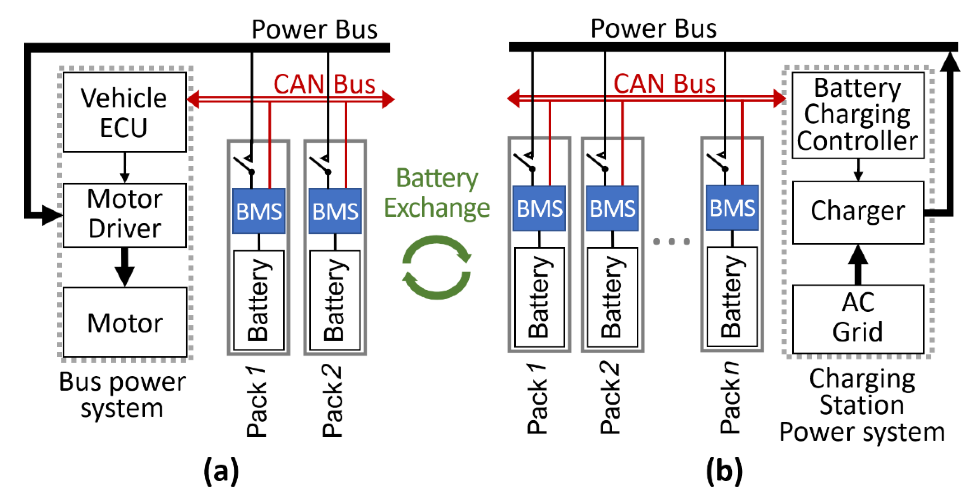
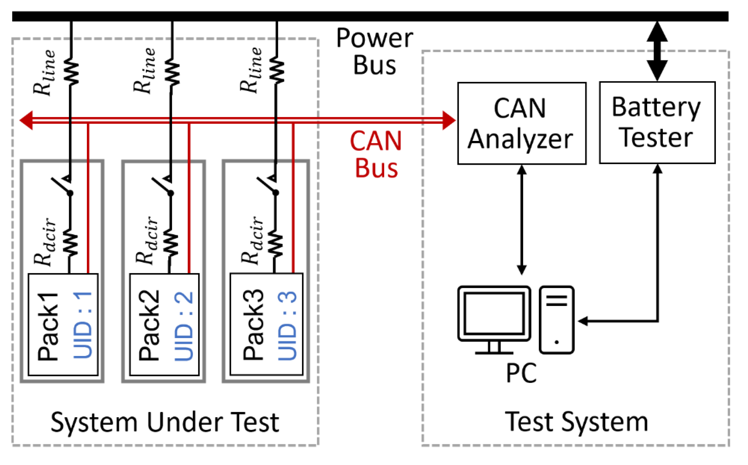
2.1. Structure of the Battery Exchange Power Network System

The new battery power network system needs to be applied to connect either to a bus power system in the power supply mode or to a charging station in the recharging mode, as shown in Figure 1. Through battery exchanging, the battery packs carry energy from the charging station to connect to a power supply system to drive a load. In either mode of operation, multiple SRB packs are connected together by both a controller area network (CAN) bus and a power bus to form a battery power network. The management control connection CAN can be extended to the electronic control unit (ECU) of the vehicle in Figure 1a or the battery charging controller (BCC) of the charging station in Figure 1b. When the battery power network is connected to the ECU, it performs power supply discharging management, and when it is connected to the BCC, it performs recharging management.
A SRB pack consists of battery cells, a BMS, and a power switch. The BMS not only monitors its own battery cells but also controls the connection of the cells to the power bus through a power switch. The BMS also communicates with other BMSs through the CAN bus to establish a management network. When a specific battery pack needs to be removed, a release button is pressed to notify the BMS to log out from the management network and turn off its power switch before the battery pack is removed. When inserting a new SRB pack into a power network, both the CAN and power buses are connected to the BMS. Then, the BMS power switch is turned on. The BMS then starts its network connection, status synchronization, and controls the power switch.

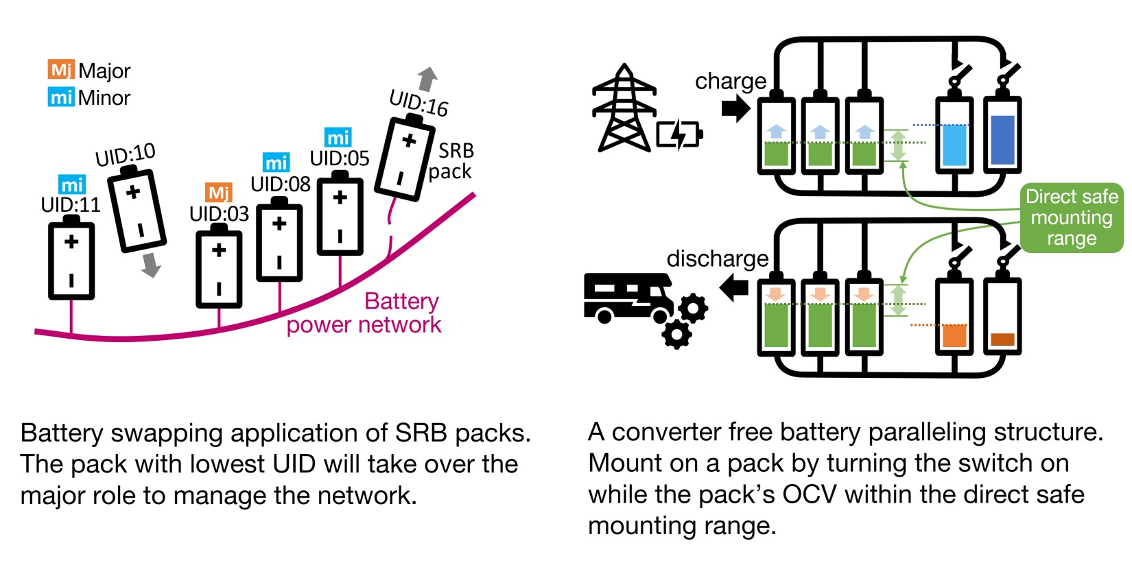
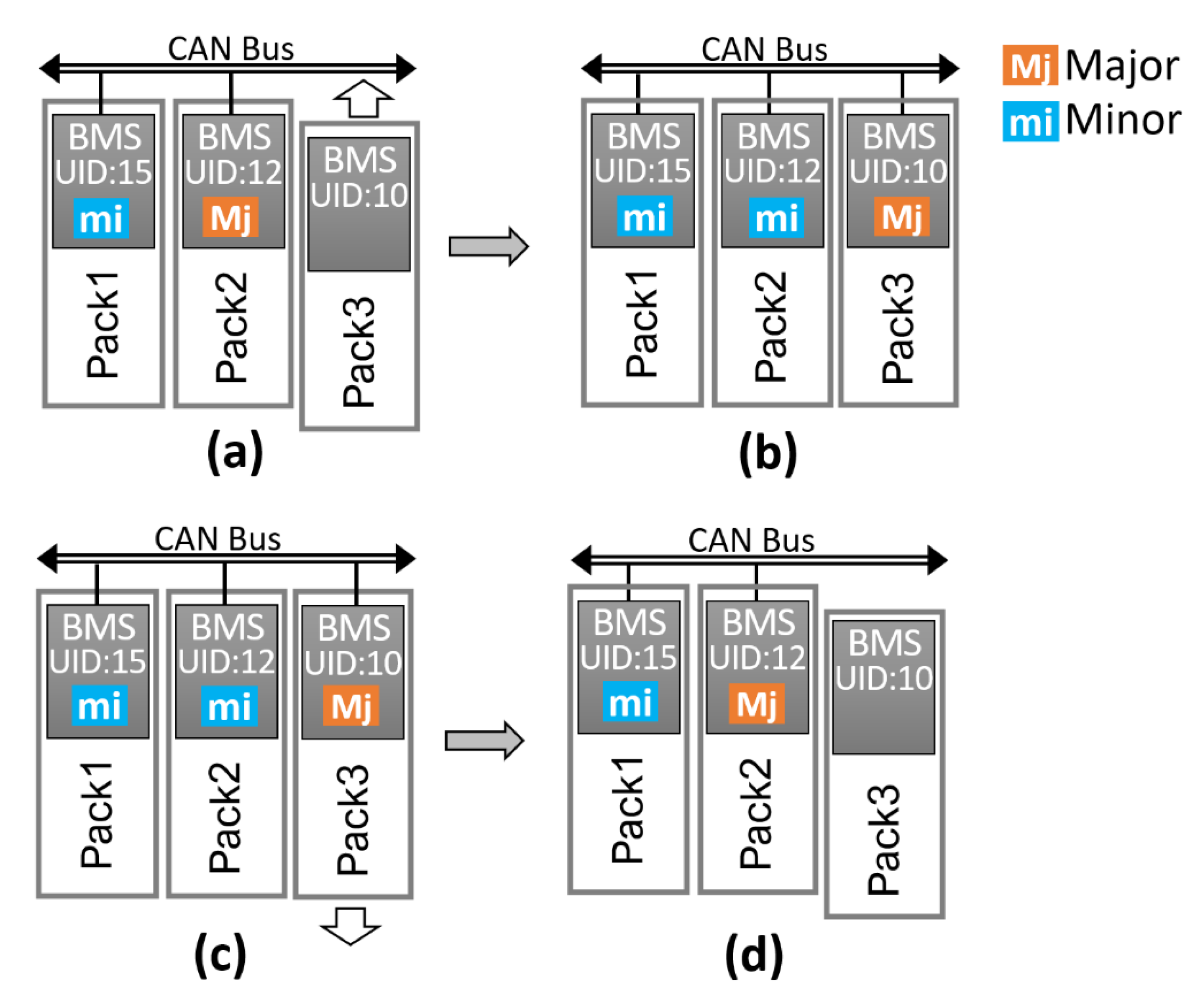
2.2. Determination of Major SRB Pack

Because the SRB pack connects to the power bus without a DC/DC converter, a major SRB controller must be chosen among the SRB packs in the system to safely and effectively coordinate the connections of the packs to the power bus. Figure 2 shows how the major SRB pack is determined and how it is replaced by a new one when the previous major pack fails or is removed. Each SRB pack is assigned a unique serial identification (UID) number. The SRB pack with the lowest UID number gets the highest priority to assume the role of major. For example, in Figure 2a, the UID number of the newly added Pack3 is 10, which is lower than the UID number of the original major Pack2 (12). After Pack3 is installed, Pack2 no longer acts as the major; it becomes a minor, and Pack3 becomes the new major, as shown in Figure 2b. As shown in Figure 2c, if Pack3 has to be removed at a later point in time, it will send an abdicating broadcast message, and Pack2 will again assume the role of major, as shown in Figure 2d.
The host determination mechanism is implemented collectively with two state machines in the BMS; the network major status state machine is used to determine whether there exists an alive host in the BMS network, and the pack role state machine is used to distinguish the role of the local BMS whether a major or a minor. However, only the network major state machine of the major SRB pack can issue major executives and realize state broadcasting on the network. The state machines of other battery packs in the minor role simply keep track of the network status as synchronized redundancies to be a host candidate ready.
Figure 3a shows the diagram of the network major status state machine updating the network-wide status, as recognized by an SRB pack. The state machine may be in either of the following two states in the network: with the major alive and without the major alive; the initial default status is the failsafe passive “without major” status. In an E1 event, a minor receives a major state broadcast from the major, and the network major status gets updated according to the message contents. When a live major no longer exists, timeout on “not receiving from the major” triggers the E2 event in the minors. Their network major statuses are changed to “without major.” When the major battery pack announces that it is relinquishing the role of major and becomes a minor, the E3 event occurs, and the network major status switches to “without major,” allowing other battery packs to synchronize; the candidate with the lowest UID number then assumes the role of major.
The decision on whether an SRB pack is a major or a minor is made by the pack role state machine, as shown in Figure 3b. The default value at the initial connection is “minor.” When an SRB pack is first turned on, it listens to the broadcast to synchronize a pack member table (PMT) with the full information of all the packs in the battery power network. Then, a unique slot number of the physical slot it plugged in is broadcasted to join the battery power network. After that, every SRB pack reports its status periodically in sync with other members. The slot number, UID number, voltage, current, temperature, etc., of the SRB pack are broadcast to all members for all packs to be synchronized with an up-to-date PMT. An example of the PMT is presented in Section 2.4.
The pack role state machine examines the network major status. If the status is “without major,” the PMT is complete and up-to-date; if the UID number of the pack is the lowest in the network PMT, the E4 event occurs, which makes the pack assume the role of major (the pack role status is switched to “major”). The minor battery pack must be ready to assume the role of major to execute the major function without additional initialization. Even when a pack becomes a major, the broadcast of reports on the local pack status, listening in to the network status, and synchronization of PMT updates continue. Additionally, as a major, it broadcasts the network major status and coordinates the power bus connections for the minor packs to get updated and follow the power bus connection commands. After a major is assigned, if an SRB pack with a lower UID number emerges, the E5 event occurs, which triggers the major to leave its role switching the role status to minor and announcing its change in status.

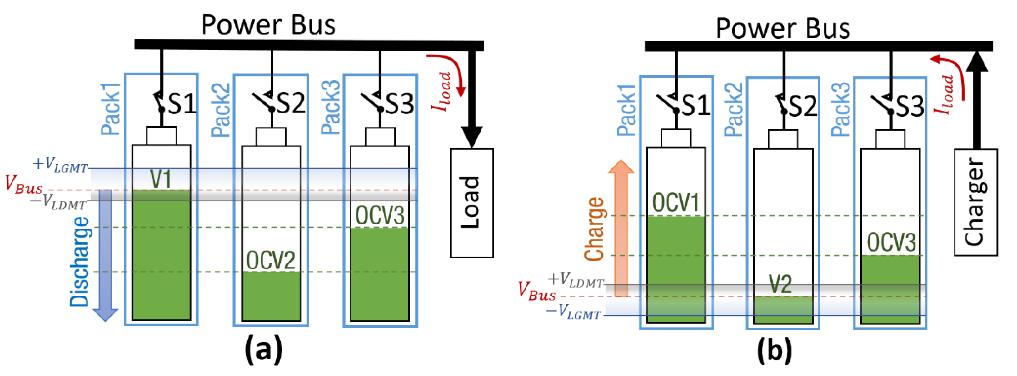
2.3. Direct Safe Mounting Threshold Voltage Formulas

The use of DC/DC converters should be avoided to connect packs to the power bus if the aim is to increase energy efficiency. Therefore, for an SRB pack to be mountable on the bus, the voltage difference between the battery pack and the power bus must be within a safe range to avoid damage to the system due to short-circuit surge [34]. The mountable voltage range must be derived. By referencing the equivalent circuit model mentioned in [34], if an SRB pack must be mounted on the power bus where other packs and loads are already connected, the instantaneous current I p a c k can be determined according to its open-circuit voltage (OCV) and connection resistances using Equation (1):
| O C V V B u s | = | I p a c k | · ( R d c i r + R l i n e + R B u s )
where V B u s is the power bus voltage, I p a c k is the battery pack current, R d c i r is the battery internal resistance, R l i n e is the connecting wire resistance, and R B u s is the equivalent impedance of the power bus depending upon what has been interconnected through the bus. Using Equation (1), we define the threshold of the maximum allowable voltage difference V T H = | O C V V B u s | . Under the same voltage threshold, the lower the R B u s value, the higher the I p a c k . Therefore, to obtain the highest I p a c k value, to set a most conservative voltage threshold, we take R B u s = 0 .
Furthermore, in case a pack would take in balance current upon connection to the power bus, the maximum current should be restricted to the maximum allowable balance current I b l n s to leave enough load bearing capacity available. Whence, the peak value of the short-circuit instantaneous current must be | I p a c k | I b l n s . Reducing from Equation (1), the voltage difference threshold Equation (2) is thus shown as follows:
V T H I b l n s · ( R d c i r + R L i n e ) · S F
where S F is the safety factor with a value less than 1.
Figure 4a shows the mounting process during discharging, where V B u s continues to decrease. Along the direction of the trend, when a SRB pack has an OCV lower than V B u s , it has a leading OCV, and it takes in balance current, whereas, when an SRB pack has an OCV higher than V B u s , it has a lagging OCV, and it is bearing the load current. Therefore, different thresholds, namely, the leading mount threshold (LDMT) voltage V L D M T and the lagging mount threshold (LGMT) voltage V L G M T , must be derived for mounting packs with OCVs on different sides of the bus voltage.
If the OCV of a battery pack is leading, then the pack can be mounted when the maximum balance current it would draw is less than the existing current capacity reserve on the bus (that is, I b l n s = I m a x I l o a d , which is the maximum rated current I m a x of the SRB packs minus the load current I l o a d being demanded). Incorporating I b l n s = I m a x I l o a d into Equation (2), we obtain V L D M T as Equation (3):
V L D M T ( I m a x I l o a d ) · ( R d c i r + R L i n e ) · S F
therefore, a pack with a leading OCV meeting | V B u s O C V | V L D M T will be allowed to mount on the power bus.
If the OCV of a battery pack is lagging, then the maximum allowable current it can bear is its rated I m a x , regardless of the load demand or the balance to leading packs. V L G M T obtained, as shown in Equation (4):
V L G M T I m a x · ( R d c i r + R L i n e ) · S F
therefore, during the discharge of power, an SRB pack with a lagging OCV satisfying | O C V V B u s | V L G M T can be mounted on the power bus to carry load demand immediately.
Figure 4a shows the discharging process with Pack1 already mounted on the bus. The red dotted line in the figure indicates the current V B u s , and the upper and lower voltage limits for SRB pack mounting are V B u s + V L G M T and V B u s V L D M T , respectively. As V B u s continues to decrease, Pack3 and Pack2 can be safely mounted on the power bus in sequence as V B u s falls within V L D M T above OCV3 and OCV2 to get ready to share the load demand. Conversely, during the charging process, the same voltage threshold definitions in Equations (3) and (4) hold with opposite signs (plus to minus and vice versa) applied for the charging and discharging processes. Therefore, the mountable voltage range can be uniformly defined with the same absolute values for the voltage differences pertaining to the leading or lagging conditions. Figure 4b shows the mounting process during charging when V B u s continues to increase as the mounted batteries get charged up. A pack with an OCV higher than V B u s is a leading OCV pack; otherwise, it is a lagging OCV pack. The red dotted line in Figure 4b shows the current V B u s . The upper and lower voltage limits for SRB pack mounting are V B u s + V L D M T and V B u s V L G M T , respectively. Therefore, when Pack2 is already mounted and as V B u s continues to increase, Pack3 and Pack1 can be safely mounted on the power bus sequentially.
These procedures are executed according to the mounting control state machine in the major SRB pack; the mounting control state machine is described in the next section. If a pack with an OCV that is already behind the mountable threshold V L G M T is plugged into the system, the pack cannot be mounted unless another cycle is restarted.

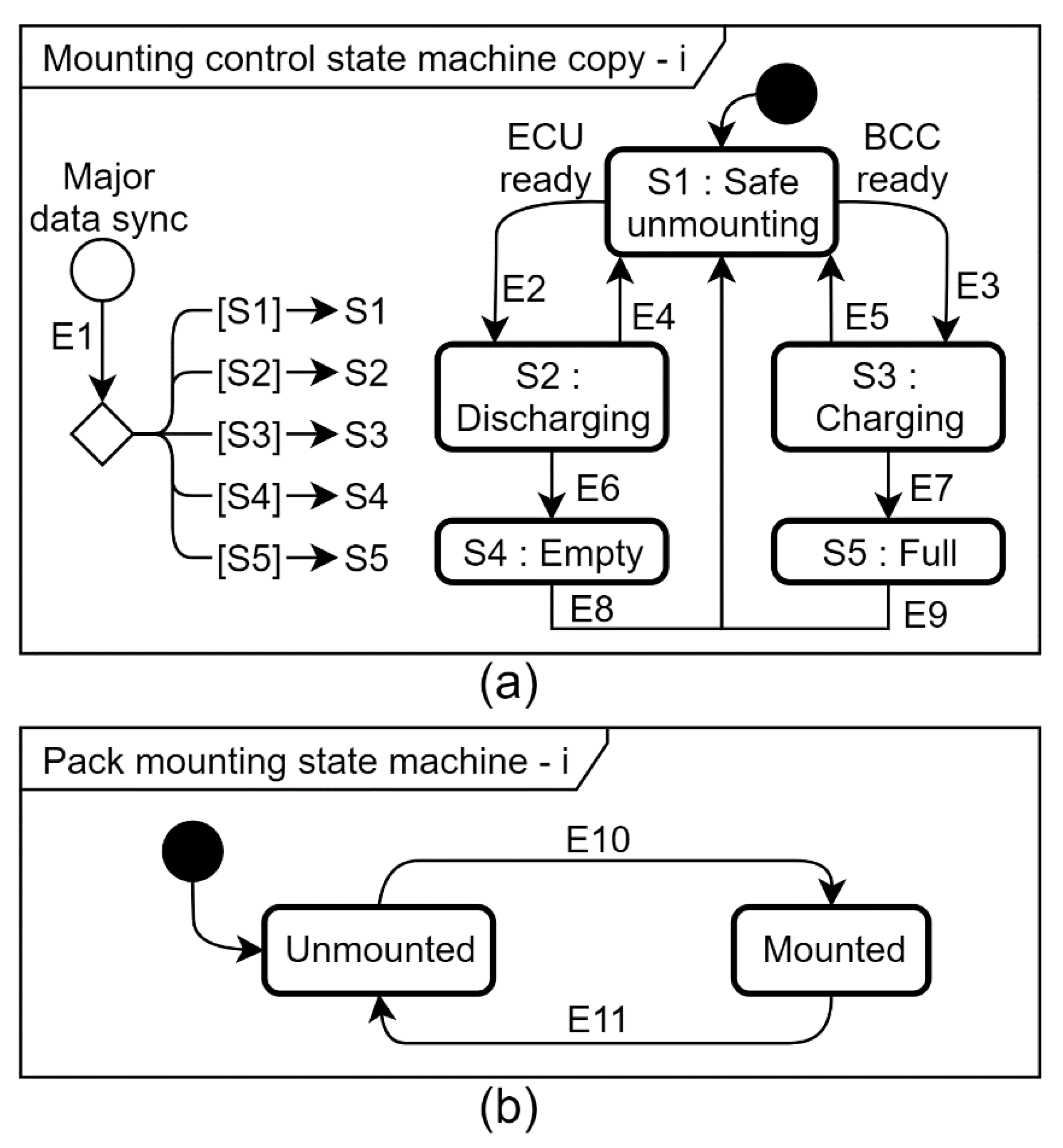
2.4. Mounting and Unmounting Control State Machine

The safety related packs mounting and unmounting to a power bus are controlled by the “mounting control state machine” in the major pack with the deployed commands in its PMT. On the other hand, a pack mounting state machine is executed in every pack, as shown in Figure 5, to do the actual mounting/unmounting of the pack onto the power bus. Only the major SRB pack analyzes the full PMT information to coordinate and broadcast commands and its status updates for all the packs to follow and to synchronize. In the minor SRB packs, a copy of the major mounting control state machine and the local pack mounting state machine are updated according to the major commands. The local status information is also broadcast for all others to keep track in their synchronized PMT.
There are five major mounting control states: safe unmounting (S1), discharging (S2), charging (S3), empty (S4), and full (S5). At the initialization or a restart, the major pack enters the S1 state, commanding all packs to enter the safe unmounting state, as shown Figure 5a; therefore, the local pack mounting state machine enters the unmounted state, as shown in Figure 5b. The major broadcasts the “mounting control state machine” status, which is any of S1, S2, S3, S4, or S5, for all packs to track accordingly. In the default initial “safe unmounting” state, the SRB packs are all unmounted to avoid a short circuit while waiting for the ready message from the ECU or BCC on the CAN bus to enter either the S2 discharging state or the S3 charging state for mounting decisions. In a minor SRB pack, the mounting control state machine only updates the major status during an E1 event upon receiving major status broadcasts. This minor version state machine does not involve system mounting controls but a status copy synchronized to the major broadcast.
The pack mounting state machine of every pack initializes to the safe unmounted state, as shown in Figure 5b, and it remains in that state until the major pack sends a new status command. This status will be broadcast as part of the PMT information of the major pack. When the major pack enters either the S2 or S3 state, the mount command can trigger the E10 event by broadcasts to the minor packs. Subsequently, when an unmount command is received or when the major returns to the S1 state, the E11 event is triggered and the pack switches to the unmounted state.
The major pack in the S2 and S3 states compares the electric measurements of all SRB packs in the PMT with the safe mounting threshold voltages to determine whether to issue mount/unmount commands for broadcasting. Meanwhile, the ECU must remain online. If the ECU was judged offline through a timeout, the E4 event occurs, the major switches back to the S1 state for safety. During the discharging state, if V B u s becomes lower than the empty voltage, then event E6 is triggered and the state switches to the S4 state. SRB packs remain mounted until the ECU sends an acknowledgment through an end power consumption message, where event E8 occurs and the major switches back to the S1 state to unmount all packs and the cycle gets restarted. In case there is a highly lagged pack in the system with a large quantity of charge remaining unmounted, it can then be re-engaged in a new cycle. In S3 state, E5 event occurs upon the reception of BCC online message times out and the major switches back to the S1 state. E7 event occurs when all mountable SRB packs are fully charged; the packs switch to the S5 full state and wait for the BCC to send an acknowledgment through an end of charging message. Upon the reception of this message by the major, E9 event occurs and the major switches back to S1, the safe unmounting state.
Table 1 presents an example PMT of the battery power network. As written in the table, there are N slots of packs, and each slot contains necessary information of the pack, such as the slot number, UID number, V p a c k , I p a c k , V B u s , and mounting state. When a new pack is inserted, its slot and UID numbers are first established. The mounting state field is updated regularly by the major. First, the average V B u s is calculated using all the measured V B u s values in the PMT. During discharging, when V p a c k is within the mountable voltage range ( V B u s V L D M T to V B u s + V L G M T ), the mounting status of that slot is set to mount with value 1; else it is set to 0. During charging, when V p a c k is within the mountable voltage range ( V B u s V L G M T to V B u s + V L D M T ), the mounting state value of that slot is set to 1; else 0. Thus, a battery power network of SRB packs with a smart network–ready BMS was designed.
Next we designed tests to verify its hot swappable functionality and managing system reliability. The findings are described in the subsequent sections.

3. Experiment

To verify the functionality and reliability of the battery network system developed in this study, we tested its charging and discharging operations with multiple SRB packs at different charge levels. Moreover, arbitrary SRB pack insertions and removals were tested to verify the hot swapping capability and the reliability of the backup redundancies in the system.

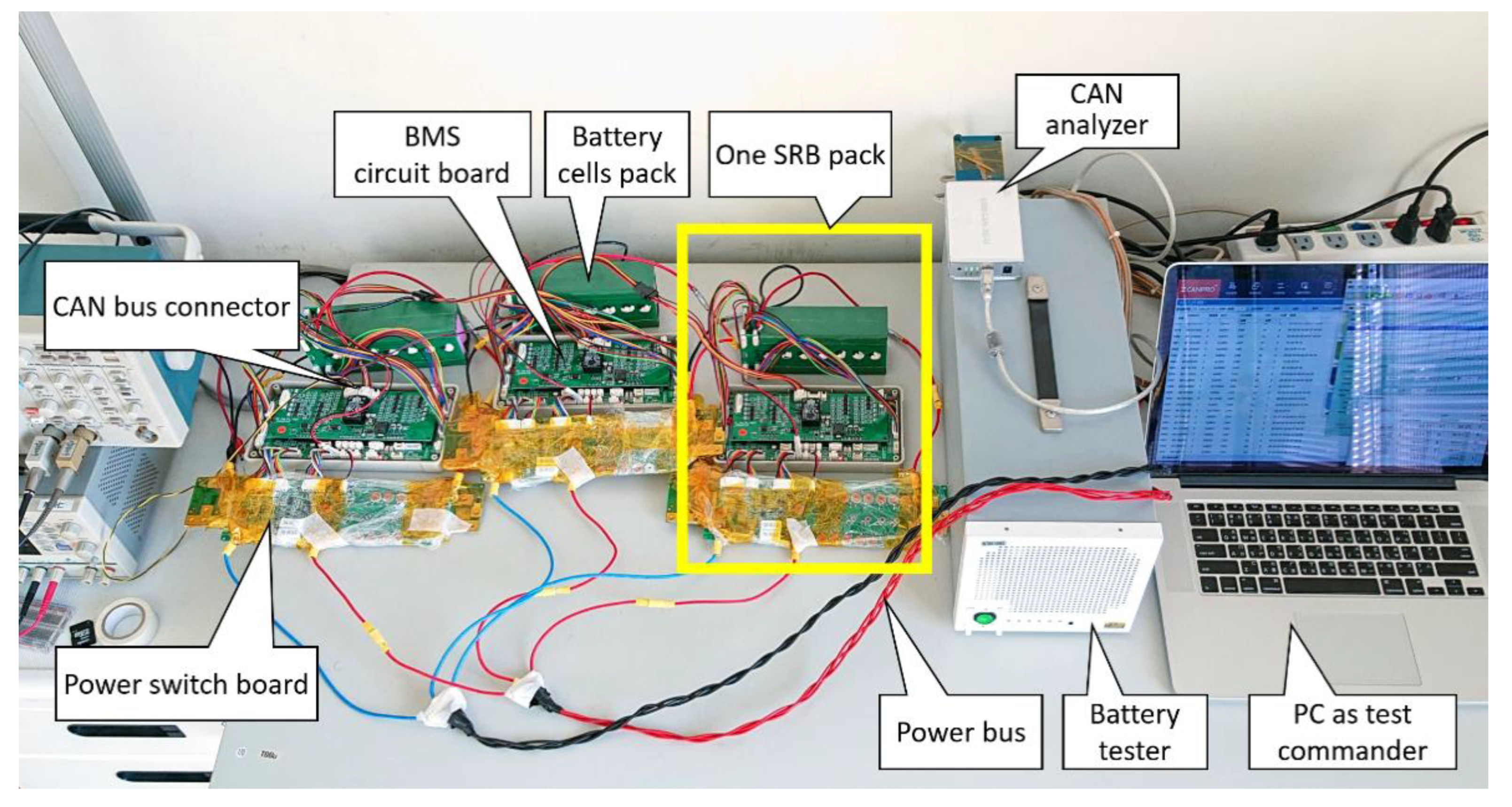
3.1. Experimental Setup

As shown in Figure 6, a battery power network of three SRB packs was tested. These packs are Pack1, Pack2, Pack3, and the UID numbers are 1, 2, and 3, respectively. A PC-based test system was set up to control the battery tester as load, and a CAN analyzer emulating the functionality of a CAN was required to enable the ECU and BCC to interact with the system under test, to log the pack status, and to perform measurements on the bus for analysis. We tested the ability of the system to perform the sequential mounting of SRB packs and arbitrary insertion and removal of SRB packs to test the major succession determination mechanism. The physical experimental setup is shown in Figure 7.
Each SRB pack was rated at 49~57.4 V of 14 Li-ion battery cells in series and 3 Ah energy capacity. These packs were controlled by a built in BMS developed in this study. In this experiment, the maximum charge and discharge C-rate was set at 1C, i.e., 3A, and the maximum load current was set at 1/2C. The data sampling frequency was 1 Hz. The pack voltage, pack current, power bus voltage, and major UID number were logged into the PC for analyses.
To calculate the safe mounting threshold voltage of the SRB pack, we had to set the parameters of the formula according to the physical characteristics of the battery pack and experimental conditions. These parameters were set as follows: rated current I m a x = 3   A , load current I l o a d = 1.5   A , battery internal resistance R d c i r = 0.6   Ω , wire resistance R l i n e = 0.05   Ω , and safety factor S F = 0.85 .
Substituting the parameters into Equation (3), we obtain the LDMT threshold as V L D M T 0.82875   V ; therefore, in this experiment, we chose V L D M T = 0.8   V . Substituting the parameters into Equation (4), we obtain the LGMT threshold as V L G M T 1.6575   V ; therefore, in this experiment, we chose V L G M T = 1.6   V . Consequently, the safe mounting voltage range of the battery pack varies with V B u s . The safe mounting voltage range was between V B u s 1.6   V and V B u s + 0.8   V during charging, and it was between V B u s 0.8   V and V B u s + 1.6   V during discharging.

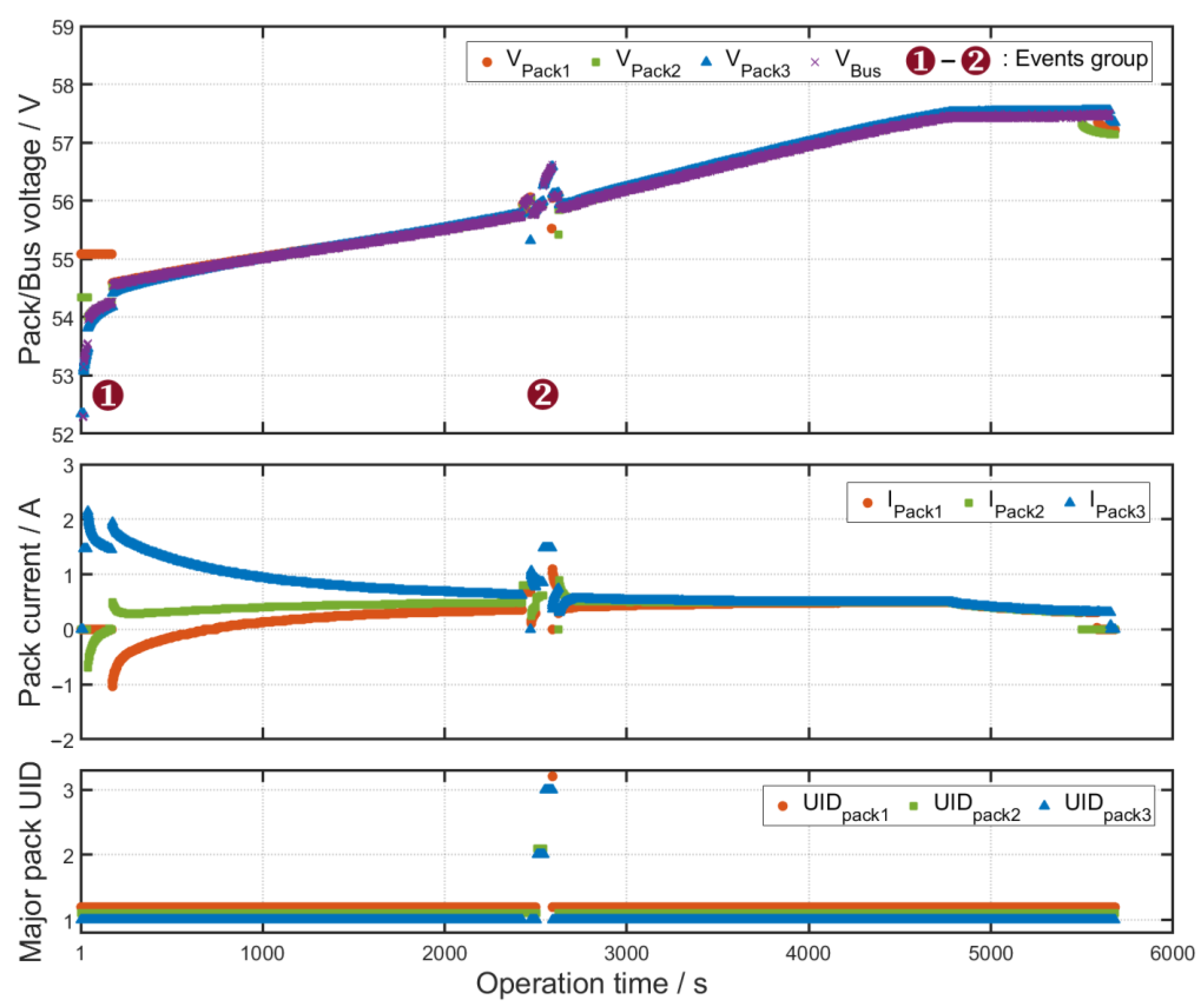
3.2. Results and Discussions on the Charging Experiment

Figure 8 illustrates the data on a charging process cycle of the battery power network system. Results pertaining to the voltage, current, and major UID number are shown in the upper, middle, and lower parts of the figure, respectively. The starting voltages of the three battery packs were 55, 54.3, and 52.3 V. A constant current–constant voltage (CC–CV) charging process was adopted, in which the CC was 1.5 A, and the CV was 57.4 V.
Briefly, at a glance, the battery packs were connected in parallel to get started, the voltages of the battery packs were similar. Therefore, they got mounted sequentially and then all together at 176 s. Afterwards, the voltages increased linearly together due to charging. At 4700 s, the charging mode is changed from the CC to CV mode. Pack2, Pack1, and Pack3 reached fully charged state and got unmounted at 5500, 5585, and 5657 s, respectively.
At the start of a cycle, mounting on to the charging power bus started from the most lagging Pack3. The interval from the start to 250 s is the sequential mounting event labeled as (1). Its details are shown in Figure 9 and will be discussed later. Pack1 with the highest OCV got mounted the last. Having an OCV higher than V B u s , after mounting, Pack1 provides extra balancing current (negative valued) to charge the low-OCV battery Pack2 and 3, and the OCV of Pack1 decreased to V B u s . As the state of charge of Pack2 and Pack3 caught up, Pack1 gradually became getting charged too. The high OCV of Pack1 resulted in a low charging current; the low OCV of Pack2 led to a high charging current, and the current of Pack3 was between the currents of Pack1 and Pack2. Therefore, the OCV of the battery packs gradually balanced out, and all the charging currents converged to 1/3 of the total charging current. At 2428 s, battery pack insertion/removal event group labeled as (2) was executed to test the robustness of the BMS management controls, in particular, the major emergence mechanism of the network system. The details of data between 2400 and 2650 s are shown in Figure 10 and will be discussed later. At 4700 s, charging mode changed from CC to CV, the charging current gradually decreased to reach fully charged state, and it was switched to complete 0 after the battery packs got unmounted one by one.
Referring to Figure 9 for the sequential mounting events group, event (1) occurred at 10 s when the most lagged Pack3 got mounted on the power bus. There was no other device connected to the bus; therefore, V B u s became equal to the OCV of Pack3, which was 52.3 V. After 5 s, the BCC started, and Pack3 got CC mode charging at 1.5 A, so Pack3 terminal voltage rose along with V B u s when the state of charge increased.
Event (2) occurred at 41 s when Pack2 OCV fell within the LDMT above the increasing V B u s , Pack2 was mounted. Thus, V B u s became the result of all the sources connected in parallel, namely, Pack2, Pack3, and the charging power source. Its value rose gradually as Pack2 and Pack3 got charged up. The OCV of Pack2 was initially higher than V B u s , causing Pack2 to deliver an additional 0.65 A balance charging current to Pack3, which increased the charging current to Pack3 to 2.15 A. Subsequently, as Pack3 caught up, both currents converged to 1/2 the charging current as their state of charge converged.
At 176 s, event (3) occurred, when Pack1 OCV fell within the LDMT the increasing V B u s , Pack1 got mounted. Thus, V B u s got determined by all the packs and the charging power source and rose gradually. The same as Pack2, the leading Pack1 provided an additional balance charging current to charge other packs initially. Afterwards the currents of all three battery packs converged towards 1/3 of the charging current as the packs were equalized. During the entire charging process, the charge and discharge currents of each pack were maintained lower than I m a x .
Figure 10 presents an enlarged view of the charging process data during 2400 to 2650 s whence some battery packs were removed and then reinserted to simulate battery swapping operations. The responses of the battery power network and the succession of the major handover process were examined. The figure shows not only the measurement data but also the event occurrences labeled by (1)–(6). These events are described as follows.
(1)
Removed Pack3 at 2428 s. The charging current shared by Pack1 and Pack2 increased, and the voltages of both packs also increased. Since Pack3 is not the major, its removal did not affect the major assignment in the battery power network.
(2)
Inserted Pack3 at 2473 s. Because the OCV of Pack3 was within the safe mounting voltage range, Pack3 was mounted right after insertion. After Pack3 got mounted, the charging currents of Pack1 and Pack2 decreased and so do their voltages. Because the present major Pack1 still had the lowest UID number, its role remained unchanged.
(3)
Removed Pack1 at 2503 s. The charging currents and voltages of both Pack2 and Pack3 increased to take up Pack1’s vacated capacity. Because the major of the battery power network was removed, Pack2, which had then the lowest UID number, assumed the role of major.
(4)
Removed Pack2 at 2543 s. Pack3 accepted 1.5 A of charging current, which increased the voltage further. The battery power network lost the major again, and Pack3, which had then the lowest UID number, assumed the role of major.
(5)
Inserted Pack1 at 2590 s. Because the OCV of Pack1 was within the safe mounting voltage range, it got mounted right after insertion. Subsequently, because Pack1 shared the charging current, the current and voltage of Pack3 decreased. In addition, Pack3 relinquished its role as major because it no longer had the lowest UID number; Pack1, which now had the lowest UID number, assumed the role of major.
(6)
Inserted Pack2 at 2626 s. Because the OCV of Pack2 was within the safe mounting voltage range, it got mounted after insertion. Pack2 shared the charging current after being mounted, and both the voltages and currents of Pack1 and Pack3 decreased. Because the current major Pack1 still had the lowest UID number, it retained its role as the major.

3.3. Results and Discussions on the Discharging Experiment

Figure 11 illustrates the data of a discharge process. Results pertaining to the voltage, current, and major UID number are shown in the upper, middle, and lower parts of the figure, respectively. The discharge current in the experiment was fixed at 1.5 A, and the empty voltage was set at 49.0 V. All battery packs were completely discharged and unmounted together after receiving the ECU ending power consumption message at 5696 s.
Briefly at a glance, the starting voltages of the three battery packs connected to the system to start with were 52, 54.7, and 52.7 V. After the initial sequential mounting sequence labeled as (1), all packs got mounted to the power bus. As Pack3 and Pack1 were just mounted, their OCVs were leading and were both lower than V B u s . They cannot take the share to supply current to the load. The lagging Pack2 with the highest OCV above V B u s supplied all the load demand plus allowed capacity margin amount of balancing currents to equalize Pack1 and Pack3. Later, as the state of charge of Pack2 dropped to the same level as Pack1 and Pack3, their current changed from getting balancing charged to load sharing discharging when the OCVs of Pack3 and Pack1 became higher than V B u s successively. Subsequently, when their OCVs gradually balanced out, their discharge currents all converged to 1/3 of the total load demand all the way towards exhaustion.
The initial mounting sequence (1) from the start to 350 s will be described in details in Figure 12. The tests of battery swap, labeled as (2), during power supply discharging were conducted from 1700 to 1950 s. The system responses to battery pack insertions/removals are describe in details in Figure 13.
At the initiation of a discharge cycle, all packs were connected to the system. First, the most lagging Pack2 with the most energy reserve got mounted on the power bus at 10 s as event (1) shown in Figure 12. Since Pack2 was the only device connected to the bus without the load demand, V B u s equaled to the OCV of Pack2, namely, 54.7 V. After 5 s, the ECU began operating and Pack2 discharged 1.5 A to the battery tester load, and V B u s dropped immediately to 54 V because of the load. It continued to decrease gradually as it continued to lose its state of charge.
As V B u s continued to drop, the LGMT fell below the OCV of Pack3; event (2) occurred at 83 s after Pack3 got mounted. At this time, V B u s was determined by the connected devices, namely, Pack2, Pack3, and the battery tester load. At the time of mounting, the OCV of Pack3 was lower than V B u s , sinking an additional 0.87 A of balancing current from Pack2 that the discharging current of Pack2 increased to 2.37 A. Subsequently, both currents converged towards approaching 1/2 the discharge current that they took on equal shares of the load.
As the discharge continued, V B u s decreased further; at 276 s, the OCV of Pack1 got included within the LGMT threshold; Pack1 could be mounted safely too, and event (3) occurred. At this time, V B u s was determined by all the packs and the discharge load. At its initial mounting, Pack1 sunk an additional 1 A of balancing charging current from other packs. Later, as they got equalized, the currents of all three packs converged to the equal share of the discharge current. During the entire discharge process, the charge and discharge currents of all the packs were properly limited below I m a x .
Figure 13 presents an enlarged view of the data between 1700 and 1950 s during the discharge process whence battery packs were removed and reinserted to simulate the battery swapping operations. The responses of the battery power network and the succession of the major handover process were examined. The figure shows not only the measurement data but also the event occurrences labeled by (1)–(6). These events are described as follows.
(1)
Removed Pack2 at 1713 s. The loading current of Pack2 got shared by Pack1 and Pack3 causing the discharge currents of both packs to increase and the voltages to decrease. Since Pack2 was not the major, its removal did not affect the major assignment in the battery power network.
(2)
Removed Pack1 at 1756 s. Pack3 had provided 1.5 A of discharge current; hence, the bus voltage dropped is even lower. Moreover, the battery power network lost the major, and thus Pack3, which had then the lowest UID number, assumed the role of major.
(3)
Inserted Pack2 at 1801 s. Because the OCV of Pack2 was within the safe mounting voltage range, it got mounted right after insertion. Subsequently, because Pack2 joined to share the discharge current, the discharge current of Pack3 decreased and its voltage increased. Moreover, Pack3 relinquished its role as the major because it was no longer the pack with the lowest UID number; subsequently, Pack2, which had then the lowest UID number, assumed the role of major.
(4)
Removed Pack3 at 1831 s. Pack2 picked up the load burden carried by Pack3 to provide 1.5 A of discharge current, so its voltage dropped. Because Pack3 was not the major, its leave did not affect the major assignment in the battery power network.
(5)
Inserted Pack1 at 1878 s. Because the OCV of Pack1 was within the safe mounting voltage range, the pack was mounted right after the insertion. Subsequently, because Pack1 joined to share the discharge current, the discharge current of Pack2 decreased, and its voltage increased. Moreover, Pack2 relinquished its role of major because it no longer had the lowest UID number, and Pack1, which had then the lowest UID number, assumed the role of major.
(6)
Inserted Pack3 at 1915 s. Because the OCV of Pack3 was within the safe mounting voltage range, it was mounted right after insertion. After the mount, Pack3 picked up its share of the discharge current, and the discharge currents of Pack1 and Pack2 decreased and their voltages increased. Since the original major Pack1 still had the lowest UID number, it retained its role as major.

3.4. Power Loss and Efficiency

To assess the energy efficiency of our direct safe power bus parallel mount algorithm with respect to those with DC/DC converter, we calculate the energy loss in all three battery packs starting from the moment the third one gets mounted, namely, the end of the sequential mounting events, to capture the most energy loss during the mounting transients. Event (1) in the charging experiment shown in Figure 8 and event (1) in the discharging experiment shown in Figure 11 are chosen as the benchmarks to be presented below. There are energy losses due to the unbalanced OCV of the newly mounted pack with respect to other already mounted packs as well as those in all the mounted packs due to load sharing as their OCV converge towards the same balanced target. If the packs were connected to the power bus through a DC/DC converter individually with an ideal equal current share strategy, all packs would have started to share equally the commanded load or charge current as shown in Figure 14b.
With direct safe mount, its equivalent circuit model is shown in Figure 14a to estimate its energy loss. Whenever there is a current flowing through a battery pack, regardless the load sharing current of balance current, it generates heat energy loss on the battery internal resistance, assuming a constant 0.6 Ω. From the experimental data, our power losses are due only to the total current through each pack, and the total energy loss is thus the accumulation of the power loss over the period under investigation as E l o s s by Equation (5):
E l o s s = t 1 t 2 I p a c k ( t ) 2 · R d c i r · d t
To compare, a system with a DC/DC converter in each battery pack would have energy loss in the internal resistance of all the packs as well as the fraction of efficiency loss of any amount of energy delivered across the DC/DC converters as shown in Figure 14b. Such a system operates the most efficiently when all packs share the equal amount of load demand. For the toughest comparison for us, we calculate the energy efficiency of the converters by Equation (6):
η e q = 1 ( E l o s s _ d c E l o s s _ l s ) / E n e t
where E l o s s _ d c is the total energy loss in direct safe mount connection, E l o s s _ l s is the energy loss in equal load sharing, E n e t is the net output energy. Such a system would have achieved the same low energy loss like our direct safe mount throughout a mounting event. The results are shown in Table 2.
The energy loss in all three SRB packs is accumulated for every 250 s period so that the decay of the excessive power loss caused by the extra balancing current due to the direct parallel mount can be shown. The total energy E n e t delivered (positive value) to the load demand or received (negative value) from the charging source by all the packs is calculated by V p a c k times I p a c k and shown in the “Net output energy” row. The E l o s s in the first period right after the completion of the direct safe mount of all three SRB packs is the highest due to the balancing current. Then the energy loss decreases gradually approaching the optimal equal load sharing amount of less than 50 J per period in both charging and discharging. It is the excessive loss above that of the equilibrium optimal equal load sharing to be compared with the conversion loss of the DC/DC converters. Therefore, the equivalent efficiency η e q can be approximated from the lower side by Equation (6).
In Table 2, the equivalent efficiency of the first period is of cause the lowest 98.3%. As the battery packs balances out gradually, it rose to 99.7% in the fourth period approaching the final ideal 100%. Thus, we got an overall efficiency about 99.2% if a direct mount lasted more than 1000 s. Therefore, as long as the load can be directly driven by the battery voltage without the modification by DC/DC converters, the direct safe mount control method of this study can provide high-efficiency battery drive with safe battery balancing and cost-effectiveness.

3.5. Summary

In summary, three SRB packs operated under the conditions of 1 C rated current, and different charging levels between 49 and 57.4 V were tested in the developed battery network system. The tests indicated successful charging with constant current (0.5 C) and constant voltage (57.4 V) modes and successful discharging to a load of 0.5 C current with various scenarios of sequential connections and arbitrary battery swaps of removals and re-insertions to verify the reliability of the backup redundancies in the battery management controls and strategies for sharing the power bus load. The major succession mechanism worked well during hot swapping. The mounting/unmounting of the packs from the power bus was executed well within voltage and current safety limits. The energy efficiency is better than a system with DC/DC converter of 98.3% efficiency with battery pack swap less busy than 250 s, and 99.2% for 1000 s. Thus, we verified the ability of our developed system to accommodate hot swapping and load sharing in both power supplying discharge as well as replenish charging. Our system was shown to be reliable, energy efficient, and convenient to use.

4. Conclusions

To realize safe online battery swapping during discharging and charging, we integrated a battery pack with network–ready BMS to design an SRB pack. In this design, multiple SRB packs are connected in parallel to form a fault-tolerant battery network system of backup redundancies in both the battery management control and the power supply. Safe mount voltage thresholds were derived that battery packs can be mounted onto the power bus only when it is safe without a DC/DC converter. This design results in better energy efficiency and cost effectiveness.
Three SRB packs at different charge levels were tested in sequential mounting and arbitrary exchanges to verify that, with the mounting mechanism, battery swap at any time is safe without affecting the ongoing charge and discharge processes. The experimental data verified that the battery power network can safely accept the charging of the charging station as well as the power demand of an electric car. Each SRB pack can serve as a backup to the major of the battery power network; the role of major seamlessly transferred from a retiring pack to another live pack to ensure that the management function ran smoothly, thus significantly improving the security of electric vehicles. As long as the packs are developed with a suitable voltage, capacity, and rated power specifications, the SRB packs and battery power network technology in this study can be used s in electric buses and battery storage power stations. The new system can be justified reliable, energy efficient, and convenient for real services.

Author Contributions

Conceptualization, C.-C.S., C.-J.C.; methodology, C.-J.C., C.-C.S.; validation, C.-J.C.; writing—original draft, C.-J.C., S.-B.J.; writing—review and editing, C.-J.C., T.-L.Y., C.-C.S.; visualization, C.-J.C.; supervision, S.-B.J. All authors have read and agreed to the published version of the manuscript.

Funding

This research received no external funding.

Data Availability Statement

Not applicable.

Acknowledgments

We thank the Industrial Technology Research Institute of Taiwan for providing the technical support. We also thank Roboy Venture Capital Co., Ltd. for partial support.

Conflicts of Interest

The authors declare that there are no conflict of interest regarding the publication of this paper.

Abbreviations

BCCbattery charging controller
BMSbattery management system
CANcontroller area network
CCcontrol current
CVcontrol voltage
DC/DCdirect current to direct current
ECUelectronic control unit
LDMTleading mount threshold
LGMTlagging mount threshold
OCVopen-circuit voltage
PMTpack member table
SRBsmart redundant battery
UIDunique serial identification

References

  1. Pielecha, J.; Skobiej, K.; Kurtyka, K. Exhaust Emissions and Energy Consumption Analysis of Conventional, Hybrid, and Electric Vehicles in Real Driving Cycles. Energies 2020, 13, 6423. [Google Scholar] [CrossRef]
  2. Woodcock, J.; Edwards, P.; Tonne, C.; Armstrong, B.G.; Ashiru, O.; Banister, D.; Beevers, S.; Chalabi, Z.; Chowdhury, Z.; Cohen, A.; et al. Public health benefits of strategies to reduce greenhouse-gas emissions: Urban land transport. Lancet 2009, 374, 1930–1943. [Google Scholar] [CrossRef]
  3. Rode, P.; Floater, G.; Thomopoulos, N.; Docherty, J.; Schwinger, P.; Mahendra, A.; Fang, W. Accessibility in cities: Transport and urban form. In Disrupting Mobility; Springer International Publishing: Cham, Switzerland, 2017; pp. 239–273. [Google Scholar] [CrossRef] [Green Version]
  4. Aftabuzzaman, M.; Mazloumi, E. Achieving sustainable urban transport mobility in post peak oil era. Transp. Policy 2011, 18, 695–702. [Google Scholar] [CrossRef]
  5. Brenna, M.; Bucci, V.; Falvo, M.C.; Foiadelli, F.; Ruvio, A.; Sulligoi, G.; Vicenzutti, A. A review on energy efficiency in three transportation sectors: Railways, electrical vehicles and marine. Energies 2020, 13, 2378. [Google Scholar] [CrossRef]
  6. Adheesh, S.; Vasisht, M.S.; Ramasesha, S.K. Air-pollution and economics: Diesel bus versus electric bus. Curr. Sci. 2016, 110, 858–862. [Google Scholar]
  7. Topal, O.; Nakir, İ. Total Cost of Ownership Based Economic Analysis of Diesel, CNG and Electric Bus Concepts for the Public Transport in Istanbul City. Energies 2018, 11, 2369. [Google Scholar] [CrossRef] [Green Version]
  8. Lu, L.; Han, X.; Li, J.; Hua, J.; Ouyang, M. A review on the key issues for lithium-ion battery management in electric vehicles. J. Power Sources 2013, 226, 272–288. [Google Scholar] [CrossRef]
  9. Gao, Z.; Lin, Z.; LaClair, T.J.; Liu, C.; Li, J.M.; Birky, A.K.; Ward, J. Battery capacity and recharging needs for electric buses in city transit service. Energy 2017, 122, 588–600. [Google Scholar] [CrossRef] [Green Version]
  10. Li, J.Q. Battery-electric transit bus developments and operations: A review. Int. J. Sustain. Transp. 2014, 10, 157–169. [Google Scholar] [CrossRef]
  11. Rogge, M.; Wollny, S.; Sauer, D.U. Fast charging battery buses for the electrification of urban public transport—A feasibility study focusing on charging infrastructure and energy storage requirements. Energies 2015, 8, 4587–4606. [Google Scholar] [CrossRef] [Green Version]
  12. Zhang, X.; Wang, G. Optimal dispatch of electric vehicle batteries between battery swapping stations and charging stations. In Proceedings of the 2016 IEEE Power and Energy Society General Meeting (PESGM), Boston, MA, USA, 17–21 July 2016; pp. 1–5. [Google Scholar]
  13. Zheng, Y.; Dong, Z.Y.; Xu, Y.; Meng, K.; Zhao, J.H.; Qiu, J. Electric Vehicle Battery Charging/Swap Stations in Distribution Systems: Comparison Study and Optimal Planning. IEEE Trans. Power Syst. 2014, 29, 221–229. [Google Scholar] [CrossRef]
  14. An, K.; Jing, W.; Kim, I. Battery-swapping facility planning for electric buses with local charging systems. Int. J. Sustain. Transp. 2019, 14, 489–502. [Google Scholar] [CrossRef]
  15. Wu, T.H.; Pang, G.K.; Choy, K.; Lam, H. An optimization model for a battery swapping station in Hong Kong. In Proceedings of the 2015 IEEE Transportation Electrification Conference and Expo (ITEC), Dearborn, MI, USA, 14–17 June 2015; pp. 1–6. [Google Scholar]
  16. Moon, J.; Kim, Y.J.; Cheong, T.; Song, S.H. Locating battery swapping stations for a smart e-bus system. Sustainability 2020, 12, 1142. [Google Scholar] [CrossRef] [Green Version]
  17. Choi, W.; Kim, J. Electrification of public transportation: Battery swappable smart electric bus with battery swapping station. In Proceedings of the 2014 IEEE Conference and Expo Transportation Electrification Asia-Pacific (ITEC Asia-Pacific), Beijing, China, 31 August–3 September 2014; pp. 1–8. [Google Scholar]
  18. Shen, H.; Wang, X.; Wang, J.; Xie, Y.; Wang, W. Vision based battery exchange robots for electric vehicle. In Proceedings of the 2012 IEEE International Conference on Mechatronics and Automation, Chengdu, China, 5–8 August 2012; pp. 2472–2476. [Google Scholar]
  19. Cheng, Y.; Tao, J. Optimization of A Micro Energy Network Integrated with Electric Bus Battery Swapping Station and Distributed PV. In Proceedings of the 2018 2nd IEEE Conference on Energy Internet and Energy System Integration (EI2), Beijing, China, 20–22 October 2018; pp. 1–6. [Google Scholar]
  20. Hemmati, M.; Abapour, M.; Mohammadi-ivatloo, B. Optimal Scheduling of Smart Microgrid in Presence of Battery Swapping Station of Electrical Vehicles. In Electric Vehicles in Energy Systems: Modelling, Integration, Analysis, and Optimization; Ahmadian, A., Mohammadi-ivatloo, B., Elkamel, A., Eds.; Springer International Publishing: Cham, Switzerland, 2020; pp. 249–267. [Google Scholar] [CrossRef]
  21. Wang, Y.; Tian, J.; Sun, Z.; Wang, L.; Xu, R.; Li, M.; Chen, Z. A comprehensive review of battery modeling and state estimation approaches for advanced battery management systems. Renew. Sustain. Energy Rev. 2020, 131, 110015. [Google Scholar] [CrossRef]
  22. Gabbar, H.A.; Othman, A.M.; Abdussami, M.R. Review of Battery Management Systems (BMS) Development and Industrial Standards. Technologies 2021, 9, 28. [Google Scholar] [CrossRef]
  23. Rahimi-Eichi, H.; Ojha, U.; Baronti, F.; Chow, M.Y. Battery management system: An overview of its application in the smart grid and electric vehicles. IEEE Ind. Electron. Mag. 2013, 7, 4–16. [Google Scholar] [CrossRef]
  24. Lawder, M.T.; Suthar, B.; Northrop, P.W.; De, S.; Hoff, C.M.; Leitermann, O.; Crow, M.L.; Santhanagopalan, S.; Subramanian, V.R. Battery energy storage system (BESS) and battery management system (BMS) for grid-scale applications. Proc. IEEE 2014, 102, 1014–1030. [Google Scholar] [CrossRef]
  25. Hu, X.; Li, S.; Peng, H. A comparative study of equivalent circuit models for Li-ion batteries. J. Power Sources 2012, 198, 359–367. [Google Scholar] [CrossRef]
  26. Cao, J.; Schofield, N.; Emadi, A. Battery balancing methods: A comprehensive review. In Proceedings of the 2008 IEEE Vehicle Power and Propulsion Conference, Harbin, China, 3–5 September 2008; pp. 1–6. [Google Scholar]
  27. Lim, D.; Anbuky, A. A distributed industrial battery management network. IEEE Trans. Ind. Electron. 2004, 51, 1181–1193. [Google Scholar] [CrossRef]
  28. Moo, C.S.; Ng, K.S.; Hsieh, Y.C. Parallel Operation of Battery Power Modules. IEEE Trans. Energy Convers. 2008, 23, 701–707. [Google Scholar]
  29. Zhang, Y.; Zhao, R.; Dubie, J.; Jahns, T.; Juang, L. Investigation of current sharing and heat dissipation in parallel-connected lithium-ion battery packs. In Proceedings of the 2016 IEEE Energy Conversion Congress and Exposition (ECCE), Milwaukee, WI, USA, 18–22 September 2016; pp. 1–8. [Google Scholar]
  30. Li, Y.; Han, Y. A module-integrated distributed battery energy storage and management system. IEEE Trans. Power Electron. 2016, 31, 8260–8270. [Google Scholar] [CrossRef]
  31. Lin, K.H.; Yu, L.R.; Moo, C.S.; Juan, C.Y. Analysis on parallel operation of boost-type battery power modules. In Proceedings of the 2013 IEEE 10th International Conference on Power Electronics and Drive Systems (PEDS), Kitakyushu, Japan, 22–25 April 2013; pp. 809–813. [Google Scholar]
  32. Stroe, D.I.; Swierczynski, M.; Kær, S.K.; Teodorescu, R. Degradation behavior of lithium-ion batteries during calendar ageing—The case of the internal resistance increase. IEEE Trans. Ind. Appl. 2017, 54, 517–525. [Google Scholar] [CrossRef] [Green Version]
  33. Piłatowicz, G.; Marongiu, A.; Drillkens, J.; Sinhuber, P.; Sauer, D.U. A critical overview of definitions and determination techniques of the internal resistance using lithium-ion, lead-acid, nickel metal-hydride batteries and electrochemical double-layer capacitors as examples. J. Power Sources 2015, 296, 365–376. [Google Scholar] [CrossRef]
  34. Lee, S.; Kim, J. Inrush current estimation and hot-swapping for safe parallel battery pack. Int. J. Electron. 2020, 107, 1609–1624. [Google Scholar] [CrossRef]
  35. Hsu, C.T.; Sheng, S.; Sun, Q.; Li, P.; Lehman, B. Increased energy delivery for parallel battery packs with no regulated bus. In Proceedings of the Intelec 2012, Scottsdale, AZ, USA, 30 September–4 October 2012; pp. 1–8. [Google Scholar]
Figure 1. Battery exchange power system comprising SRB packs. The battery packs are connected either (a) to a bus power system in the power supply mode or (b) to a charging station in the recharging mode.
Energies 14 02841 g001
Figure 2. Example event sequences describing how the major SRB pack is determined: (a,b) show the newly added pack assuming the role of major, and (c,d) demonstrate that after the major SRB pack is removed, the SRB with the lowest UID number assumes the role of major.
Energies 14 02841 g002
Figure 3. (a) i-th copy of the network major state machine and (b) pack role state machine of the i-th SRB pack.
Energies 14 02841 g003
Figure 4. Schematic of battery pack mounting operation. (a) Mounting process during discharging. (b) Mounting process during charging.
Energies 14 02841 g004
Figure 5. (a) i-th slot copy of the battery power network mounting control state machine. (b) Pack mounting state machine of the i-th slot.
Energies 14 02841 g005
Figure 6. The schematic of charging and discharging experiment on the battery power network.
Energies 14 02841 g006
Figure 7. Physical setup of the charging and discharging experiment. The PC commands the battery tester to variate the loading and charging current to the power bus of red and black cables. The CAN bus is connected to the CAN analyzer with the PC emulating ECU/BCC functions and logging the CAN bus messages.
Energies 14 02841 g007
Figure 8. Data of a battery power network during a charging cycle.
Energies 14 02841 g008
Figure 9. Enlarged view of the sequential mounting events at the initiation of the battery pack charging cycle.
Energies 14 02841 g009
Figure 10. Enlarged view of battery pack insertion/removal events during charging.
Energies 14 02841 g010
Figure 11. Data of a battery power network discharge cycle.
Energies 14 02841 g011
Figure 12. Enlarged view of the sequential mounting events at the initiation of a battery pack discharging cycle.
Energies 14 02841 g012
Figure 13. Enlarged view of battery pack insertion/removal events during discharging.
Energies 14 02841 g013
Figure 14. (a) The different amounts of current on each battery pack due to the different pack voltage. (b) The use of DC/DC converters to achieve an optimal equal current sharing.
Energies 14 02841 g014
Table 1. Example of a simplified PMT.
slot-1slot-2slot-islot-N
Slot number12 i N
UID number521 7 2
V p a c k 48.0250.16 49.57 51.09
I p a c k 1.120 0 0
V B u s 48.0148.03 47.99 48.00
Mounting state10 0 0
Table 2. Power loss in the charging and discharging experiment.
Charging Experiment
Time (s)176–425 (250 s)426–675 (250 s)676–925 (250 s)926–1175 (250 s)overall (1000 s)
Net output energy (J)−19,917.6−20,079.3−20,196.6−20,088.1−80,281.6
E l o s s in direct connection (J)411.9250185.7152.51000.1
E l o s s in equal load sharing (J)106.8107.7108.3106.6429.4
Equivalent DC/DC efficiency (%)98.4799.2999.6299.7799.29
Discharging Experiment
Time (s)276–525 (250 s)526–775 (250 s)776–1025 (250 s)1026–1275 (250 s)overall (1000 s)
Net output energy (J)20,008.719,754.519,765.719,785.679,314.5
E l o s s in direct connection (J)449.5257.3186.3152.21045.3
E l o s s in equal load sharing (J)116.1114.1115.2116.3461.7
Equivalent DC/DC efficiency (%)98.3399.2899.6499.8299.26
Publisher’s Note: MDPI stays neutral with regard to jurisdictional claims in published maps and institutional affiliations.

