Article

Study on Spectral Radiative Heat Transfer Characteristics of a Windowed Receiver with Particle Curtain

1
College of Energy and Electrical, Hohai University, Nanjing 210098, China
2
College of Mechanics and Materials, Hohai University, Nanjing 210098, China
*
Author to whom correspondence should be addressed.
Energies 2021, 14(10), 2801; https://doi.org/10.3390/en14102801
Submission received: 13 April 2021 / Revised: 9 May 2021 / Accepted: 11 May 2021 / Published: 13 May 2021
(This article belongs to the Section A2: Solar Energy and Photovoltaic Systems)

Abstract

:
In this paper, a windowed receiver with a particle curtain is numerically simulated under full-spectrum conditions. The discrete phase model (DPM) is used to model the particle flow and interactions between the particle phase and the air phase. The scattering, absorption of the particle curtain and quartz glass window are considered in detail. The spectral characteristics of glass have an important influence on the heat transfer characteristics and the receiver efficiency. The results show that the quartz window can reduce the convective heat loss and the cavity re-radiation heat loss. Under the same conditions, the receiver efficiency of a windowed receiver with a particle curtain is increased by 11.9% compared with an aerowindow receiver with a particle curtain. Under the same mass flow, the particle curtain thickness and particle size have a non-negligible influence on the flow pattern and temperature distribution of the particle curtain. When the particle curtain thickness is low, the flow stability of the particle curtain is high; as the particle curtain thickness increases, the volume fraction of the particle curtain decreases, and the flow stability of the particle curtain decreases, which affects the shape of the curtain. The scattering and absorption characteristics of the particles are different, resulting in different net fluxes of incident radiation under the reflection of the particle curtain and the back wall. As the particle curtain thickness increases, the particle average exit temperature and the receiver efficiency show a trend of first increasing and then decreasing. When d = 30 mm, the incident radiation (G) at the position of the particle curtain is larger, the particle average exit temperature reaches 1156.72 K, and the receiver efficiency reaches 74.4%. Therefore, different particle sizes also have a significant impact on the flow pattern of the particle curtain and the radiation distribution inside it. In the range of 250–750 μm particle size, the particles average exit temperature reaches above 1150 K, and the receiver efficiency is above 72.6%. As the particle size increases, the particle average exit temperature, and the receiver efficiency show a trend of first decreasing and then increasing. When the particle size is 500 mm, the particle average exit temperature reaches 1175.8 K, and the receiver efficiency reaches 79.4%.

Graphical Abstract

1. Introduction

Thermal energy accounts for more than 90% of global energy, and almost all thermal energy comes directly or indirectly from sunlight. Solar energy can be used through different technologies, and tower solar thermal power generation systems are a good choice [1,2,3,4,5,6,7]. The receiver is a key component of the tower solar thermal power generation system in order to achieve large-scale and high-efficiency power generation. It is a bridge between the heliostat field and the power generation system, and it is also a decisive factor in the conversion efficiency of solar energy to thermal energy [8,9,10,11].
The new-generation concentrating solar power (CSP) system based on supercritical carbon dioxide (sCO2) Brayton cycle requires a higher circulating temperature, so a particle receiver with silicon-based particle material for the heat transfer and storage medium is proposed [10]. After being focused, the sunlight is directly irradiated in the receiver, and a large number of particles fall from the upper part of the receiver to form a particle curtain to absorb the sunlight [12]. In this heating process, the particle can theoretically be heated to above 1000 °C [13,14,15,16,17,18]. Compared with other solar receivers, the advantages of solid-particle solar receivers are [19]:
  • Solid particles can directly absorb the concentrated solar radiation without additional fluid pipes;
  • Solid particles can reach a higher working temperature;
  • Solid particles can also be used as the heat exchange medium and heat storage medium at the same time, without additional pipes and heat exchange equipment;
  • The cost of using particles as a medium is lower;
  • The system can reach a high degree of stability at high temperatures.
The initial research on falling curtain particle receivers was proposed by Martin and Vitko [20] of Sandia National Laboratories (SNL) in 1982. Subsequently, Falcone [21] evaluated the performance of solid particle solar receivers with different particle sizes. Chen et al. [22] developed an improved model in 2007, and Siegel et al. [23] verified it through a pilot-scale on-sun experiment in 2010. The experimental results show that the receiver efficiency exceeds 50%, and the maximum temperature of the pellet inlet and outlet rises to 250 °C. Kumar A et al. [24,25,26] studied the optical and radiation characteristics of particles in the falling receiver and evaluated the particles as the energy storage system medium. Kim et al. [27,28] analyzed the effects of wind speed and direction on the receiver operating characteristics. In order to eliminate the adverse effects of environmental wind and particle circulation loss on the performance of the particle receiver, the researchers proposed corresponding optimization schemes. Tan et al. [29] proposed that the use of an aerowindow can effectively suppress heat convection loss, achieve the purpose of reducing convection and radiation loss, and improve the efficiency of the receiver. Quartz glass has a strong selectivity for the transmission and absorption of solar radiation [30,31]. Therefore, most of the solar radiation can pass through the quartz glass and enter the cavity containing the particle curtain. However, the long spectrum radiation in the cavity cannot be transmitted out of the quartz glass, and the convective heat loss is greatly reduced. This is one of the main reasons why the receiver efficiency can be improved by using the quartz glass window [32,33].
At present, the research on high-temperature particle receiver is in its infancy. There are a few theoretical analyses on the heat transfer characteristics of the particle receiver, especially the light thermal conversion process under the particle flow state under the action of high radiation heat flux, and the application analysis of a quartz window structure has not been reported [1,3]. In this paper, based on the discrete phase model (DPM) and discrete ordinates (DO) radiation model, the coupled heat transfer process between the quartz window, the particle curtain, and the cavity wall are considered, and the full spectrum characteristics of the radiation process, especially the spectral transmission of quartz glass, are considered. The flow structure, heat transfer characteristics and overall thermal performance of the receiver are analyzed.

2. Model Analysis

2.1. Physical Model and Boundary Conditions

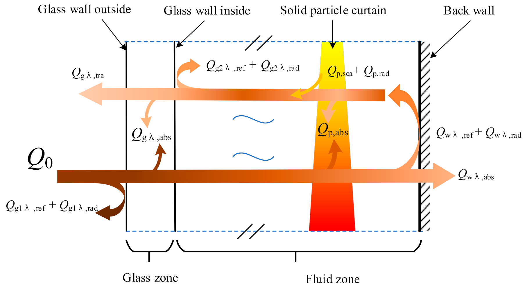
The initial temperature of particles falling from the top of the cavity is 873 K, and the mass flow rate is 5 kg/s. Particles flow out from the bottom of the receiver and enter the heat exchanger. The outlet is accompanied by air reflux, and the reflux temperature is 300 K. The wall of the cavity is adiabatic, and a diffuse reflection condition is adopted for any wavelength. For comparison, with the aerowindow receiver, the geometric model of the windowed receiver is shown in Figure 1, with the same size as the Sandia National Laboratory (SNL) experimental model, with a length of 2 m, a width of 1.5 m and a height of 3 m, a radiation window of 1.5 m × 1.5 m, and a falling opening of d = 40 mm. Considering the spectral transmittance of quartz glass, the receiver is divided into two calculation domains: (1) solid calculation domain of quartz glass material, (2) fluid calculation domain of air and particle flow. Considering the calculation cost, this paper does not consider the cooling of the quartz window but focuses on the transport process of radiation energy in the main components, including quartz window, particle curtain, and cavity wall, as shown in Figure 2.

2.2. Numerical Model

2.2.1. Gas-Phase Equation

In the vicinity of the particles, due to the interaction with the particles, the airflow in the receiver is affected by resistance and buoyancy convection heat transfer. In the preliminary experiments of Hruby and Burolla [34], it was found that the volume fraction of particles is small, and the collision probability between particles is low. Therefore, this paper adopts the two-way coupled Euler–Lagrange method, including gas-solid two-phase heat and momentum exchange, to simulate gas-particle flow. The collision between particles and the resulting momentum transfer are ignored in this study.
Continuity equation:
ρ U j x j = 0
Momentum equation:
x j ρ U i U j = P x i + x j μ U i x j + U j x i ρ u i u j ¯ + S i M ρ g i
Energy equation:
x j ρ U j C p T = x j α T x j ρ C p u j T ¯ + S i T
where ρ is the air phase density, μ is the aerodynamic viscosity, p is the pressure, Cp is the specific heat capacity of the air, α is the thermal conductivity of the air, and S i M and S i T are the generalized source terms generated by the gas phase due to the presence of particles.
Turbulent stress and heat flux density are expressed as follows:
ρ u i u j ¯ = μ t U i x j + U j x i 2 3 ρ δ i j k
ρ C p u j T ¯ = μ t Pr t T x j
where δ i j is the Kronecker δ function, δ i j = 1 when i = j and 0 when i j , k is the turbulent kinetic energy, Prt is the turbulent number and taken as 0.9, and is the turbulent viscosity, μ t = ρ C μ k 2 / ε where C μ = 0.09 , and ε is the turbulence dissipation.

2.2.2. Particle Phase Equation

The trajectory of the particles can be predicted by integrating the force balance on the particle, which is written in a Lagrange reference frame.
Motion equation:
d u p , i d t = 18 μ ρ p d p 2 C D Re p , i 24 u i u P , i + g i ρ p ρ ρ p
C D = 24 Re p , i 1 + 0.15 Re p , i 2 / 3
Re p , i = ρ d p u p , i u / μ
where u i is the air velocity, u p , i is the particle velocity, ρ p is the density of particle, d p is the particle diameter, C D is the drag coefficient, and Re p , i is the relative Reynolds number.
Energy equation:
ρ p c p π d p 3 6 d T p d t = Nu α p π d p T T P + π d 2 ε p σ T R 4 T p 4
Nu = 2 + 0.6 Re p 1 / 2 Pr 1 / 3
where α p is the thermal conductivity of solid particle, Pr is the Prandtl number of gas flow, ε p is the particle emissivity, σ is the Stefan-Boltzmann constant, and TR is the radiation temperature G / 4 σ 1 / 4 .
Where G is the incident radiation:
G = Ω = 4 π I d Ω
where, I is the radiation intensity and Ω is the solid angle.

2.2.3. Particle Radiation Model

The radiative transfer governing equation for the spectral intensity of an absorbing, emitting, and scattering medium at position r in the direction s can be written as [35,36,37]:
I λ ( r , s ) s + a λ + σ s I λ ( r , s ) = a λ n 2 I b λ + σ s 4 π 0 4 π I λ ( r , s ) Φ s , s d Ω
where λ is the wavelength, a λ is the spectral absorption coefficient, n is the refractive index, σ s is the scattering coefficient, s is optical path length, s is the scattering direction vector, Ω is the solid angle, Φ is the phase function, and I b λ is the blackbody intensity given by the Planck function. The scattering coefficient, scattering phase function, and refractive index are assumed to be independent of wavelength, while gas scattering is ignored. For non-gray radiation, the absorption, emission, and scattering of radiation by particles are included in each spectral band. At the same time, the emission and absorption source terms of particles are also coupled into the energy equation (see Equation (9)).
The contribution of the particulate phase appears in the RTE as:
( I s ) + a + a p + σ p I ( r , s ) = a n 2 σ T 4 π + E p + σ p 4 π 0 4 π I r , s Φ s , s d Ω
where a p is the equivalent absorption coefficient due to the presence of particulates, E p is the equivalent emission of the particles, and σ p is the equivalent particle scattering factor that used in the scattering terms.
E p = lim V 0 n = 1 N ε p n A p n σ T p n 4 π V
a p = lim V 0 n = 1 N ε p n A p n V
where ε p n , A p n and T p n are the emissivity, projected area, and temperature of particle n, respectively. The summation is over N particles in volume V. The projected area A p n of the particle is defined as:
A p n = π d p n 2 4
where d p n is the diameter of the n th particle, f p n is the scattering factor associated with the n th particle.
The equivalent particle scattering factor is computed during particle tracking and is defined as:
σ p = lim V 0 n = 1 N 1 f p n 1 ε p n A p n V

3. Simulation Method

The spectral distribution of solar radiation intensity on the earth’s surface is similar to that of blackbody radiation at 5800 K. A total of 99% of its energy is concentrated in the wavelength range of 0.2–3 μm. However, it is attenuated to AM1.5 solar radiation by solar-terrestrial propagation, atmospheric scattering, and absorption, and its radiation intensity is mainly concentrated in the ultraviolet to the near-infrared band (0.3–1 μm). The temperature of the inner wall of the receiver is usually 1500–2300 K, and the temperature of the cavity is significantly lower than that of the solar surface. The spectral distribution characteristics of the radiation intensity are mainly concentrated in 1–4 μm. As shown in Figure 3, quartz glass has obvious spectral selective transmission characteristics. The transmittance of short wavelength (0.25–2 μm) can generally reach more than 90%, while long wavelength radiation (>3 μm) transmission is almost non-existent.
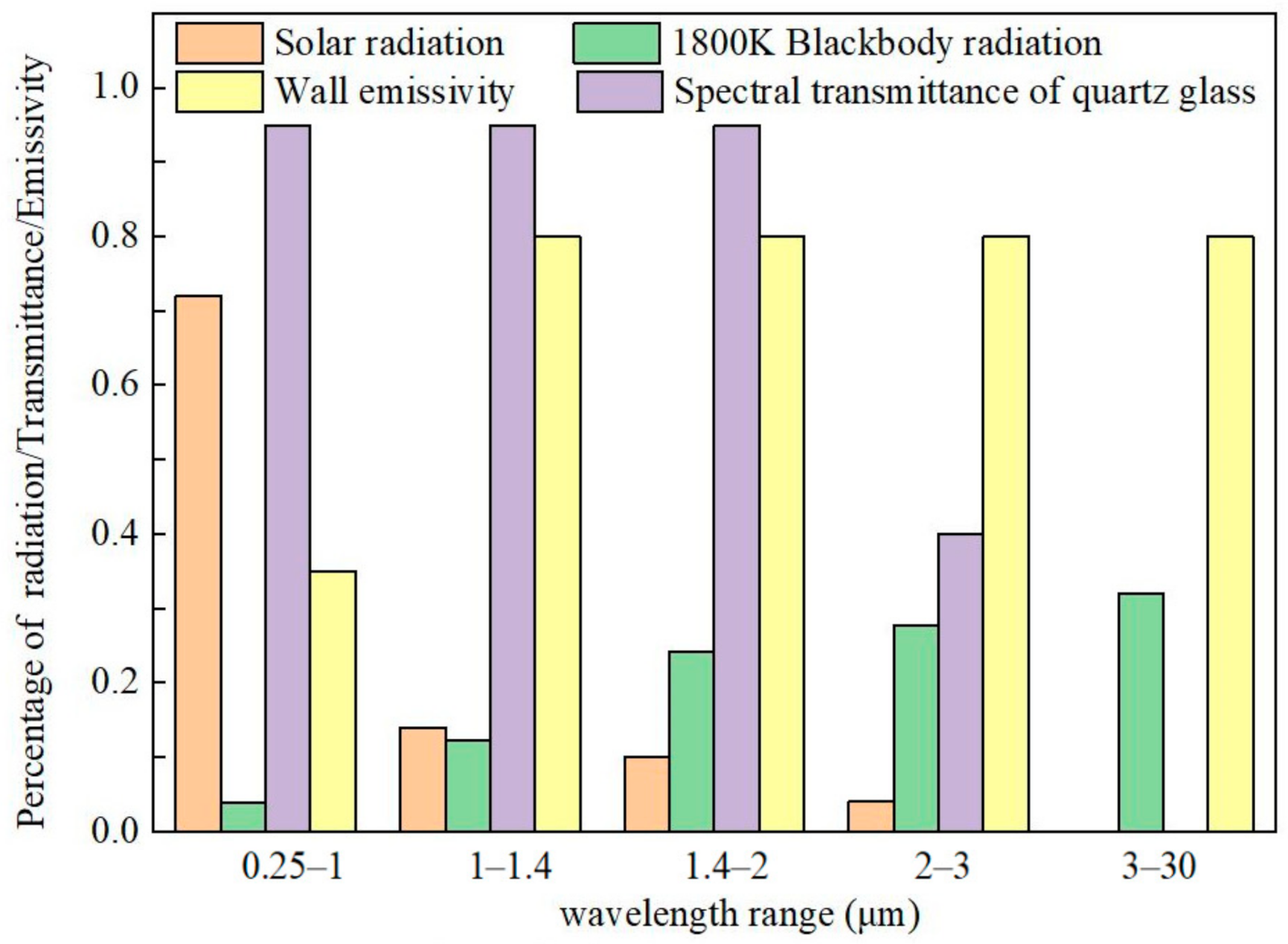
In this paper, CFD simulation software is used to calculate and analyze the different working conditions under a steady-state condition. The coupling solver is used to calculate the gas-solid interaction. The discrete method is used to consider the spectral characteristics of radiation. Here the overall radiation is divided into five bands: 0.25–1, 1–1.4, 1.4–2, 2–3, and 3–30 μm (as shown in Figure 4). The particle parameters are shown in Table 1.
Using structured grid division, in order to verify the grid independence, five different node numbers of 895,584, 199,274, 395,069, 542,961, and 731,136 were used for the grid calculation. The grid number is higher than 542,961, the error of temperature and velocity distribution is less than 2%. In order to save computing resources and time, while maintaining the accuracy of the calculation, a grid with 395,069 nodes was used for the calculation in subsequent research. In this grid, the characteristics of speed, pressure, and temperature can achieve high convergence.

4. Discussion

4.1. Comparative Analysis with Aerowindow Receiver

According to the relevant literature data [38], the use of an aerowindow can effectively reduce convection losses, and studies have shown that the optimal jet velocity is 8 m/s. Therefore, this paper uses the parameters when the jet velocity of the air curtain is 8 m/s for comparison and uses a particle size of 650 nm. Table 2 compares the main performance parameters of the aerowindow receiver and quartz window receiver. It can be seen that the particle average exit temperature and the receiver efficiency are significantly improved and that the convection loss is effectively reduced by using the quartz glass window and taking advantage of its spectral selective transmission.

4.2. Influence of Different Particle Curtain Thickness

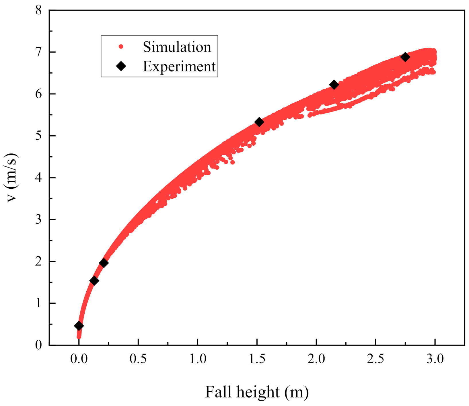
At present, there are few studies on the effect of particle curtain thickness on the efficiency of the receiver. The influence of particle curtain thickness and particle concentration on the receiver has not been analyzed yet. In this paper, based on a fixed mass flow rate of 5 kg/s, the thickness of the particle curtain and the particle concentration of the particle curtain is changed by varying the opening width. Five thicknesses of 10, 20, 30, 40, and 50 mm are selected for simulation analysis. Figure 5 shows the change of particle rate with the increase in fall height. It can be seen that the trend of particle velocity on fall height is basically consistent with the experimental data [28]. With the increase in fall height, the particle velocity increases rapidly up to about 0.5 m, after which it increases slowly.

4.2.1. Analysis of Flow Characteristics

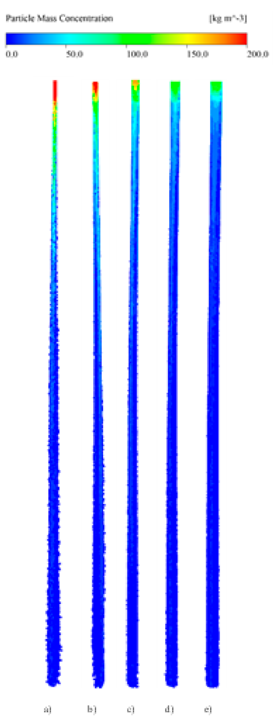
Figure 6 shows the particle concentration distribution under different particle inlet thicknesses. With the increase in particle inlet thickness, the particle concentration of the particle curtain gradually decreases; when the particle inlet thickness is low, the initial particle concentration is higher, and with the increase in falling height, the particle concentration decreases; however, when the particle inlet thickness is high, the thickness of the particle curtain appears to increase after initially decreasing. This is due to the low concentration of particles near the bottom outlet and the backflow of some external gas on the inner wall side, resulting in the deformation and inward migration of particles. This is consistent with the experimental results of the change in particle curtain thickness with the change in particle inlet thickness [28], which verifies the validity and rationality of the model.
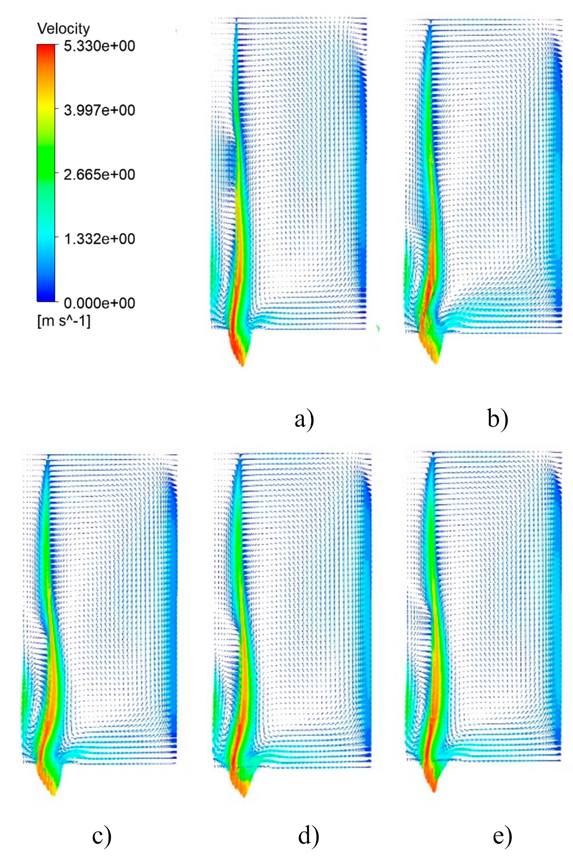
Figure 7 shows the velocity field distribution of the particle curtain when section x = −1 m, with different particle inlet thicknesses. It can be seen that the air around the particle curtain entrains and forms a vortex. When the particle inlet thickness is low, because the particle curtain is thin and the particle volume fraction is large, the particle curtain flow is relatively stable, and the surrounding entrainment phenomenon range is relatively small; with the increase in the opening, the increase in the particle curtain thickness, and the decrease in the particle volume fraction, the surrounding air entrainment range is larger, the eddy current intensity is larger, and the outlet reflux speed is also increased. Therefore, the particle inlet thickness has a significant influence on the particle flow pattern and the gas flow characteristics in the cavity of the receiver.

4.2.2. Analysis of the Temperature Distribution Characteristics

Figure 8 shows the particle temperature distribution under different particle inlet thicknesses. It can be seen from the figure that with the change in the particle inlet thickness, the particle temperature distribution also has obvious changes. In the process of photothermal conversion, the radiation heat transfer between the cavity wall and the particles cannot be ignored. When the inlet thickness of the particles is 10 mm, the thickness of the particle curtain is very small, the temperature distribution of the particles on both sides of the curtain has little difference, and the temperature is more uniform. With the increase in the inlet thickness of the particles, the thickness of the particle curtain also increases. Due to the incident radiation and the heating of the wall behind the cavity, there is a significant temperature difference between the front and rear sides of the particle curtain and the central part, and the particles on the right side also show a significant temperature rise. With the increase in the inlet thickness of the particles, the volume fraction of the particle curtain decreases and the diffusion trend of the particle curtain to the left and right sides is relatively obvious, but the diffusion phenomenon before and after the particle curtain decreases with the increase in the particle size. On the whole, the temperature distribution of the particle curtain near the back wall shows that the temperature distribution near the two sides of the wall is higher and that the temperature decreases from the middle towards both sides.
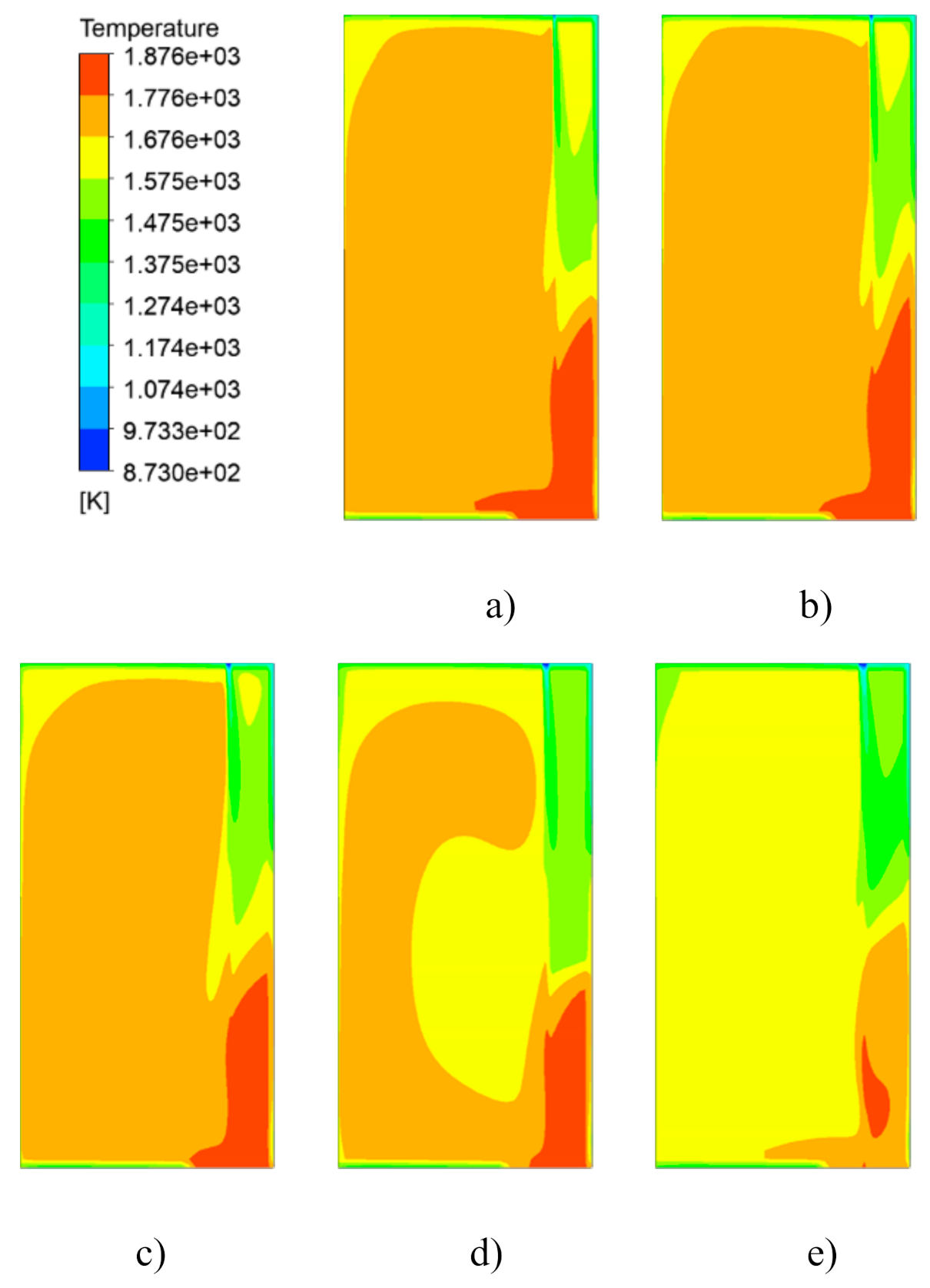
Figure 9 shows the gas temperature distribution at different particle inlet thicknesses. When d = 10 mm, it can be seen that the temperature difference between the particle curtain and the back wall of the cavity is significantly higher. The internal temperature of the receiver has obvious temperature differences, and the lowest and highest temperature regions are the upper and lower parts of the particle curtain and the back wall of the cavity, respectively.
At this time, the thickness of the particle curtain is low, the particle curtain is dense, and the flow stability of the particle curtain is high. Corresponding to the flow field in Figure 6, the entrainment between the particle curtain and the rear wall forms a vortex, and the turbulence intensity at the outlet is small. With the increase in the inlet thickness of particles, the particle curtain becomes sparse gradually, the flow stability decreases, and the turbulence intensity at the outlet increases, which makes the air in the chamber in front of the particle curtain receive sufficient convective heat transfer, and so the temperature increases.

4.2.3. Radiation Field Analysis

In this paper, the influence of spectral radiation is considered. The incident radiation G is defined as follows:
G = 0 Ω = 4 π I λ d Ω d λ
Figure 10 shows the distribution of the incident radiation G (normal incidence along the y direction) at the central section in the direction of the width of the particle screen. As can be seen from the figure, the incident radiation tends to be high in the middle and low on both sides. When d = 30 mm, the incident radiation is higher as a whole, while when d = 50 mm, the overall radiation intensity is low. This is due to the different scattering and absorption characteristics of the particle curtain with different thicknesses, resulting in a different net flux of incident radiation under the reflection of particle curtain and back wall. This trend is consistent with the results of subsequent thermal efficiency analyses.

4.2.4. Receiver Efficiency

The efficiency of the receiver is defined as follows:
η = Q P Q s = m c p T o u t T i n I A s
where m is the mass flow rate of particles, c p is the specific heat of particles, which in this paper is a constant, T i n and T o u t are the average temperature of particle inlet and outlet, respectively, I is the incident radiation intensity, and A s is the radiation window area.
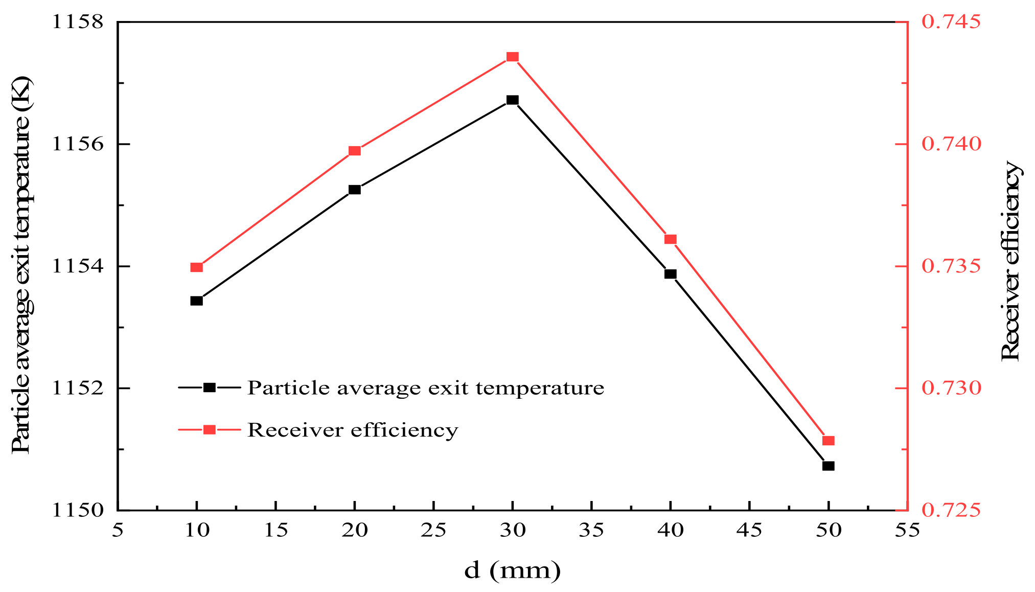
Figure 11 shows the particle average exit temperature and the receiver efficiency under different curtain thickness conditions. When the thickness of the particle inlet is 10–50 mm, the average temperature of the particle outlet is more than 1153 K, and the efficiency of the receiver is more than 0.728. With the increase in particle entrance thickness, the particles’ average exit temperature and the receiver efficiency first increase and then decrease. Therefore, the thickness and volume fraction of the particle curtain cannot be neglected for its overall efficiency.

4.3. Influence of Different Particle Size

Figure 12 shows the effect of different particle sizes on the temperature distribution of the exit particles. The particle mass flow rate remains unchanged (5 kg/s), and the thickness of the particle curtain is 30 mm. Four kinds of particles with particle sizes of 250, 350, 500, 650 and 750 μm are simulated and analyzed. It can be seen from Figure 12 that the exit temperature of particles with different particle sizes presents a trend of high in the middle and low on both sides along the x direction. The particle size is small, and the influence of vortices on the two sides is strong when the particles fall freely, which leads to the obvious dispersion of particles due to thickness. The temperature of particles in front of the curtain was significantly higher than that of the back wall.
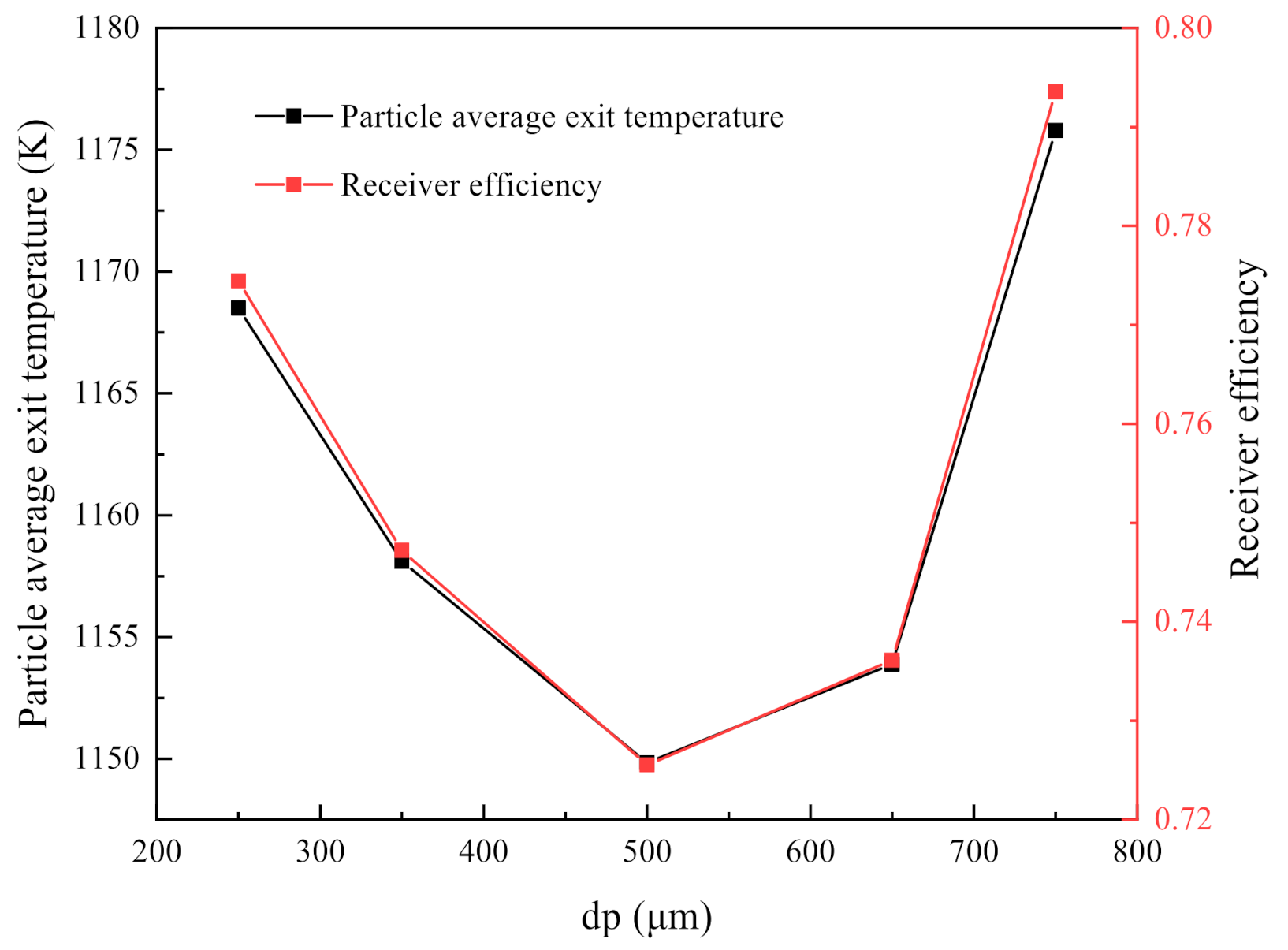
Figure 13 shows the particle average exit temperature and the receiver efficiency with different particle sizes. When the particle size is between 250 and 750 μm, the average temperature of the particle outlet is above 1150 K, and the receiver efficiency is above 0.725. With the increase in particle size, the particle average exit temperature and the receiver efficiency increase at first and then decrease. The main reason is that the particle size has a significant impact on the flow pattern and radiation distribution of the particle curtain, thus affecting the radiation heat loss and thermal efficiency.

5. Conclusions

The discrete phase model (DPM) is used to model the particle flow and its interaction in a particle screen heat receiver with a quartz window. The influences of the scattering and absorption of the particle curtain, and the spectral characteristics of quartz glass on the heat transfer characteristics and thermal efficiency of the heat receiver, are considered in detail. The conclusions are as follows:
  • With the advantage of selective transmission, the heat loss of convection and re-radiation in the cavity can be reduced, and the particle average exit temperature and the receiver efficiency can be noticeably improved.
  • When the mass flow rate is the same, the influence of the inlet thickness of particles on the flow pattern and temperature distribution of the particle curtain cannot be ignored. The volume fraction and flow stability of the particle curtain decrease with the increase in the thickness of the particle curtain. When the thickness of the particle inlet is 10–50 mm, with the increase in particle entrance thickness, the particle average exit temperature and the receiver efficiency first increase and then decrease.
  • The particle size also has a significant effect on the flow pattern and the radiation distribution inside the curtain. The exit temperature of particles with different particle sizes presents a trend of high in the middle and low on both sides along the width. The particle size is small, and the influence of vortices on the two sides of the curtain is strong when the particles fall freely, resulting in the obvious dispersion of particles in a thickness distribution. The particle temperature in the front of the curtain is significantly higher than that in the back wall side. When the particle size is between 250 and 750 μm, the particle average exit temperature and the receiver efficiency first decrease and then increase with the increase in the particle size.

Author Contributions

L.W. contributed significantly to analysis and manuscript preparation. P.W. contributed to the conception of the study and performed the data analyses. L.Y. and J.L. helped perform the analysis with constructive discussions. All authors have read and agreed to the published version of the manuscript.

Funding

Open Fund of Key Laboratory for Thermal Science and Power Engineering of Ministry of Education, Tsinghua University (THS201920011) and the Fundamental Research Fund for Central Universities (B200202172) is acknowledged.

Conflicts of Interest

The authors declare that they have no known competing financial interests or personal relationships that could have appeared to influence the work reported in this paper.

References

  1. Behar, O.; Khellaf, A.; Mohammedi, K. A review of studies on central receiver solar thermal power plants. Renew. Sustain. Energy Rev. 2013, 23, 12–39. [Google Scholar] [CrossRef]
  2. Benoit, H.; Spreafico, L.; Gauthier, D.; Flamant, G. Review of heat transfer fluids in tube-receivers used in concentrating solar thermal systems: Properties and heat transfer coefficients. Renew. Sustain. Energy Rev. 2016, 55, 298–315. [Google Scholar] [CrossRef]
  3. Ho, C.K.; Iverson, B.D. Review of high-temperature central receiver designs for concentrating solar power. Renew. Sustain. Energy Rev. 2014, 29, 835–846. [Google Scholar] [CrossRef] [Green Version]
  4. Islam, T.; Huda, N.; Abdullah, A.; Saidur, R. A comprehensive review of state-of-the-art concentrating solar power (CSP) technologies: Current status and research trends. Renew. Sustain. Energy Rev. 2018, 91, 987–1018. [Google Scholar] [CrossRef]
  5. Ju, X.; Xu, C.; Hu, Y.; Han, X.; Wei, G.; Du, X. A review on the development of photovoltaic/concentrated solar power (PV-CSP) hybrid systems. Sol. Energy Mater. Sol. Cells 2017, 161, 305–327. [Google Scholar] [CrossRef]
  6. Tan, T.; Chen, Y. Review of study on solid particle solar receivers. Renew. Sustain. Energy Rev. 2010, 14, 265–276. [Google Scholar] [CrossRef]
  7. Tang, N.; Zhang, Y.; Niu, Y.; Du, X. Solar energy curtailment in China: Status quo, reasons and solutions. Renew. Sustain. Energy Rev. 2018, 97, 509–528. [Google Scholar] [CrossRef]
  8. Calderón, A.; Palacios, A.; Barreneche, C.; Segarra, M.; Prieto, C.; Rodriguez-Sanchez, A.; Fernández, A.I. High temperature systems using solid particles as TES and HTF material: A review. Appl. Energy 2018, 213, 100–111. [Google Scholar] [CrossRef] [Green Version]
  9. Gobereit, B.; Amsbeck, L.; Buck, R.; Pitz-Paal, R.; Röger, M.; Müller-Steinhagen, H. Assessment of a falling solid particle receiver with numerical simulation. Sol. Energy 2015, 115, 505–517. [Google Scholar] [CrossRef] [Green Version]
  10. Ho, C.; Christian, J.; Gill, D.; Moya, A.; Jeter, S.; Abdel-Khalik, S.; Sadowski, D.; Siegel, N.; Al-Ansary, H.; Amsbeck, L.; et al. Technology Advancements for Next Generation Falling Particle Receivers. Energy Procedia 2014, 49, 398–407. [Google Scholar] [CrossRef] [Green Version]
  11. Ho, C.K. A review of high-temperature particle receivers for concentrating solar power. Appl. Therm. Eng. 2016, 109, 958–969. [Google Scholar] [CrossRef] [Green Version]
  12. Kumar, A.; Kim, J.-S.; Lipiński, W. Radiation absorption in a particle curtain exposed to direct high-flux solar irradiation. J. Sol. Energy Eng. 2018, 140, 061007. [Google Scholar] [CrossRef]
  13. Knott, R.C.; Sadowski, D.L.; Jeter, S.M.; Abdel-Khalik, S.I.; Al-Ansary, H.A.; El-Leathy, A. Sintering of Solid Particulates Under Elevated Temperature and Pressure in Large Storage Bins for Thermal Energy Storage. In Proceedings of the ASME 2014 8th International Conference on Energy Sustainability Collocated with the ASME 2014 12th International Conference on Fuel Cell Science, Engineering and Technology, Boston, MA, USA, 30 June–2 July 2014. [Google Scholar] [CrossRef]
  14. Siegel, N.P.; Gross, M.D.; Coury, R. The Development of Direct Absorption and Storage Media for Falling Particle Solar Central Receivers. J. Sol. Energy Eng. 2015, 137, 041003. [Google Scholar] [CrossRef]
  15. Zhao, W.; Sun, Z.; Alwahabi, Z.T. Emissivity and absorption function measurements of Al2O3 and SiC particles at elevated temperature for the utilization in concentrated solar receivers. Sol. Energy 2020, 207, 183–191. [Google Scholar] [CrossRef]
  16. Nie, F.; Bai, F.; Cui, Z.; Zhao, Z.; Wang, Z. Cold-state experimental study on discharge characteristics of solid particles in a gravity driven moving bed solar receiver. Sol. Energy. 2020, 195, 14–26. [Google Scholar] [CrossRef]
  17. Nie, F.; Bai, F.; Cui, Z.; Wang, Z. Properties of solid particles as heat transfer fluid in a gravity driven moving bed solar receiver. Sol. Energy Mater. Sol. Cells 2019, 200, 110007. [Google Scholar] [CrossRef]
  18. Kang, Q.; Flamant, G.; Dewil, R.; Baeyens, J.; Zhang, H.; Deng, Y. Particles in a circulation loop for solar energy capture and storage. Particuology 2019, 43, 149–156. [Google Scholar] [CrossRef]
  19. Jiang, K.; Du, X.; Kong, Y.; Xu, C.; Ju, X. A comprehensive review on solid particle receivers of concentrated solar power. Renew. Sustain. Energy Rev. 2019, 116, 109463. [Google Scholar] [CrossRef]
  20. Martin, J.; Vitko, J., Jr. ASCUAS: A Solar Central Receiver Utilizing a Solid Thermal Carrier. 1982. Available online: https://www.osti.gov/biblio/5663779-ascuas-solar-central-receiver-utilizing-solid-thermal-carrier (accessed on 20 November 2020).
  21. Falcone, P.K.; Noring, J.E.; Hruby, J.M. Assessment of a Solid Particle Receiver for a High Temperature Solar Central Receiver System. 1985. Available online: https://www.osti.gov/biblio/6023191-assessment-solid-particle-receiver-high-temperature-solar-central-receiver-system (accessed on 12 December 2020).
  22. Chen, H.; Chen, Y.; Hsieh, H.-T.; Siegel, N.P. CFD Modeling of Gas Particle Flow within a Solid Particle Solar Receiver. In Proceedings of the Solar Energy; ASME International, Denver, CO, USA, 8–13 July 2006; pp. 37–48. [Google Scholar]
  23. Siegel, N.P.; Ho, C.K.; Khalsa, S.S.; Kolb, G.J. Development and Evaluation of a Prototype Solid Particle Receiver: On-Sun Testing and Model Validation. J. Sol. Energy Eng. 2010, 132, 021008. [Google Scholar] [CrossRef]
  24. Gobereit, B.; Amsbeck, L.; Happich, C.; Schmücker, M. Assessment and improvement of optical properties of particles for solid particle receiver. Sol. Energy 2020, 199, 844–851. [Google Scholar] [CrossRef]
  25. Kumar, A.; Kim, J.-S.; Lipiński, W. Radiation Characteristics of a Particle Curtain in a Free-Falling Particle Solar Receiver. In Proceedings of the ASME 2017 Heat Transfer Summer Conference, Bellevue, WA, USA, 9–12 July 2017. [Google Scholar]
  26. Siegel, N.; Gross, M.; Ho, C.; Phan, T.; Yuan, J. Physical Properties of Solid Particle Thermal Energy Storage Media for Concentrating Solar Power Applications. Energy Procedia 2014, 49, 1015–1023. [Google Scholar] [CrossRef] [Green Version]
  27. Kim, K.; Moujaes, S.F.; Kolb, G.J. Experimental and simulation study on wind affecting particle flow in a solar receiver. Sol. Energy 2010, 84, 263–270. [Google Scholar] [CrossRef]
  28. Kim, K.; Siegel, N.; Kolb, G.; Rangaswamy, V.; Moujaes, S.F. A study of solid particle flow characterization in solar particle receiver. Sol. Energy 2009, 83, 1784–1793. [Google Scholar] [CrossRef]
  29. Tan, T.; Chen, Y.; Chen, Z. Performance of Solid Particle Receivers with or Without the Protection of an Aerowindow. In Proceedings of the ASME 2008 2nd International Conference on Energy Sustainability, Jacksonville, FL, USA, 10–14 August 2008; pp. 95–104. [Google Scholar]
  30. Hang, T.; Ping, X.H. Study on spectral properties and energy conversion mechanism of glass. J. Inorg. Mater. 2013, 28, 696–700. [Google Scholar]
  31. Xi, G.F. Optical and Spectral Properties of Glass; Shanghai Scientific and Technical: Shanghai, China, 1992. [Google Scholar]
  32. Wang, P.; Liu, D.; Xu, C.; Xia, L.; Zhou, L. A unified heat transfer model in a pressurized volumetric solar receivers. Renew. Energy 2016, 99, 663–672. [Google Scholar] [CrossRef]
  33. Wang, P.; Li, J.; Bai, F.; Liu, D.; Xu, C.; Zhao, L.; Wang, Z. Experimental and theoretical evaluation on the thermal performance of a windowed volumetric solar receiver. Energy 2017, 119, 652–661. [Google Scholar] [CrossRef]
  34. Hruby, J.; Steele, B.; Burolla, V. Solid particle receiver experiments: Radiant heat test. Solid Part. Receiv. Exp. Radiant Heat Test 1984, A05, 1. [Google Scholar] [CrossRef]
  35. Thomasson, P.G.; Cheng, P. Two-dimensional radiating gas flow by a moment method. AIAA J. 1964, 2, 1662–1664. [Google Scholar]
  36. Raithby, G.D.; Chui, E.H. A Finite-Volume Method for Predicting a Radiant Heat Transfer in Enclosures with Participating Media. J. Heat Transf. 1990, 112, 415–423. [Google Scholar] [CrossRef]
  37. Chui, E.H.; Raithby, G.D. Implicit Solution Scheme to Improve Convergence Rate in Radiative Transfer Problems. Numer. Heat Transf. Part B Fundam. 1992, 22, 251–272. [Google Scholar] [CrossRef]
  38. Tan, T.; Chen, Y. Protection of an Aerowindow, One Scheme to Enhance the Cavity Efficiency of a Solid Particle Solar Receiver. In Proceedings of the Volume 1: Heat Transfer in Energy Systems; Thermophysical Properties; Heat Transfer Equipment; Heat Transfer in Electronic Equipment; ASME International, San Francisco, CA, USA, 19–23 July 2009; pp. 611–618. [Google Scholar]
Figure 1. Geometric model of windowed receiver.
Energies 14 02801 g001
Figure 2. The energy transport in the radiation process. (Subscript “g1” indicates the outer wall of the glass field, “g2” indicates the inner wall of the glass domain, “p” indicates the particle curtain, “w” indicates the rear wall of the cavity, “abs” indicates absorption, “ref” indicates reflection, “tra” indicates transmission, “rad” indicates radiation).
Energies 14 02801 g002
Figure 3. Solar radiation (AM1.5) and blackbody radiation distribution with quartz glass spectral transmittance.
Energies 14 02801 g003
Figure 4. Discrete hypothesis of solar radiation and the spectral radiation characteristics of its components.
Energies 14 02801 g004
Figure 5. Particle velocity distribution (d = 10 mm).
Energies 14 02801 g005
Figure 6. Particle concentration distribution in the direction of thickness at different particle inlet thickness. (a) d = 10; (b) d = 20; (c) d = 30; (d) d = 40; (e) d = 50 mm.
Energies 14 02801 g006
Figure 7. Velocity vector graphs of different particle inlet thicknesses when the section x = −1 m. (a) d = 10; (b) d = 20; (c) d = 30; (d) d = 40; (e) d = 50 mm.
Energies 14 02801 g007
Figure 8. Particle temperature distribution. (a) d = 10; (b) d = 20; (c) d = 30; (d) d = 40; (e) d = 50 mm.
Energies 14 02801 g008
Figure 9. Air temperature distribution of different particle inlet thicknesses at the section x = −1 m. (a) d = 10; (b) d = 20; (c) d = 30; (d) d = 40; (e) d = 50 mm.
Energies 14 02801 g009
Figure 10. Particle curtain width incident radiation distribution.
Energies 14 02801 g010
Figure 11. Particle average exit temperature and the receiver efficiency at different particle inlet thicknesses.
Energies 14 02801 g011
Figure 12. Particle exit temperature distribution. (a) 250; (b) 350; (c) 500; (d) d = 650; (e) d = 750 μm.
Energies 14 02801 g012
Figure 13. Particle average exit temperature and receiver efficiency at different particle sizes.
Energies 14 02801 g013
Table 1. Solid particles’ physical parameters.
TypesValue
Density (kg/m3)3200
Specific heat (J/kg-K)1085
Solar radiation absorption rate0.9
Thermal conductivity (W/m-K)6.67
Table 2. Performance comparison between the aerowindow particle curtain receiver and quartz window particle curtain receiver.
TypesAerowindowQuartz Window
Particle average exit temperature K11081154
The receiver efficiency61.7%73.6%
Convection heat loss4.8%1.2%
Publisher’s Note: MDPI stays neutral with regard to jurisdictional claims in published maps and institutional affiliations.