
Improving the Irradiance Data Measured by Silicon-Based Sensors


Abstract
1. Introduction
2. Instruments
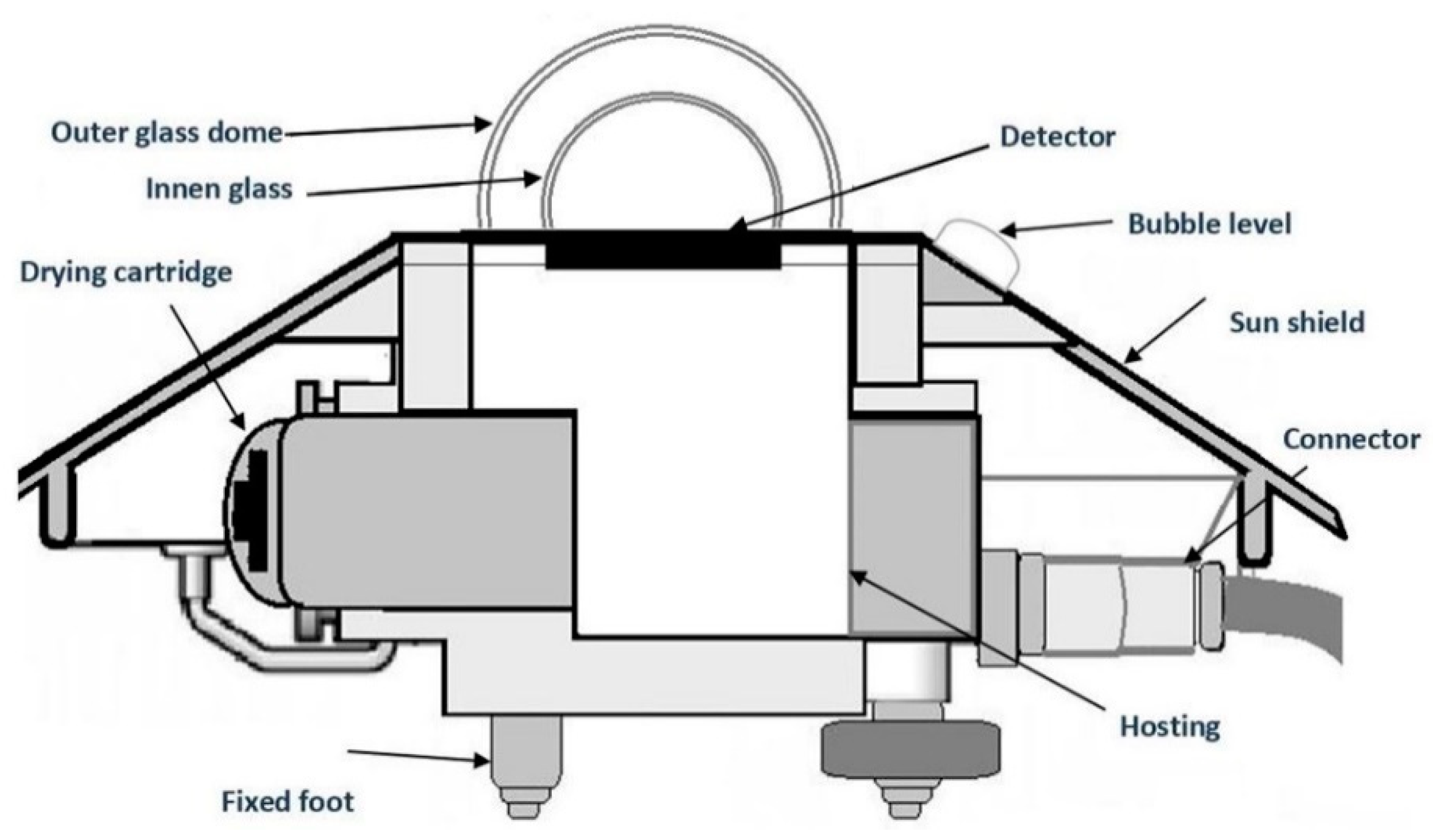
2.1. Thermopile Pyranometer
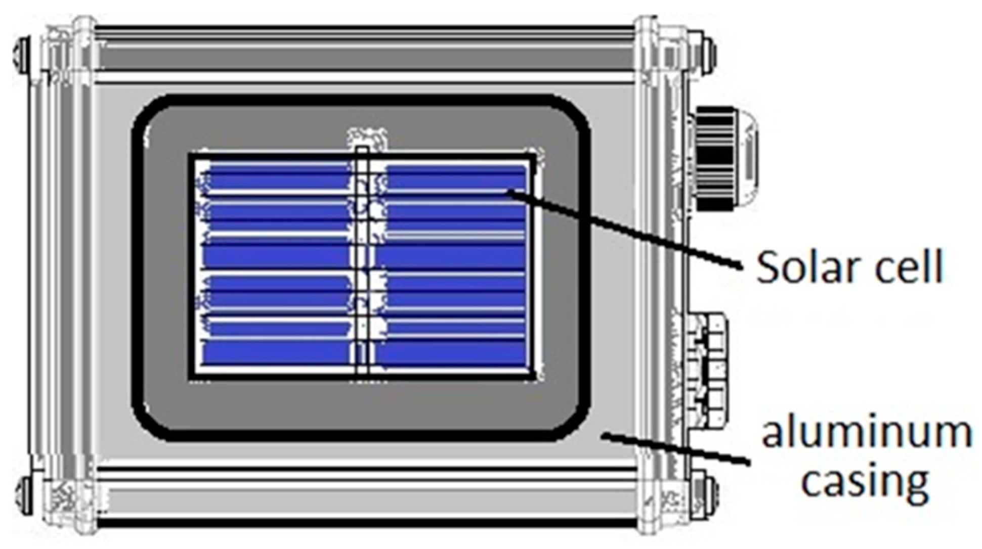
2.2. Silicon Sensors

2.3. Differences between Sensors
2.3.1. Temperature Response
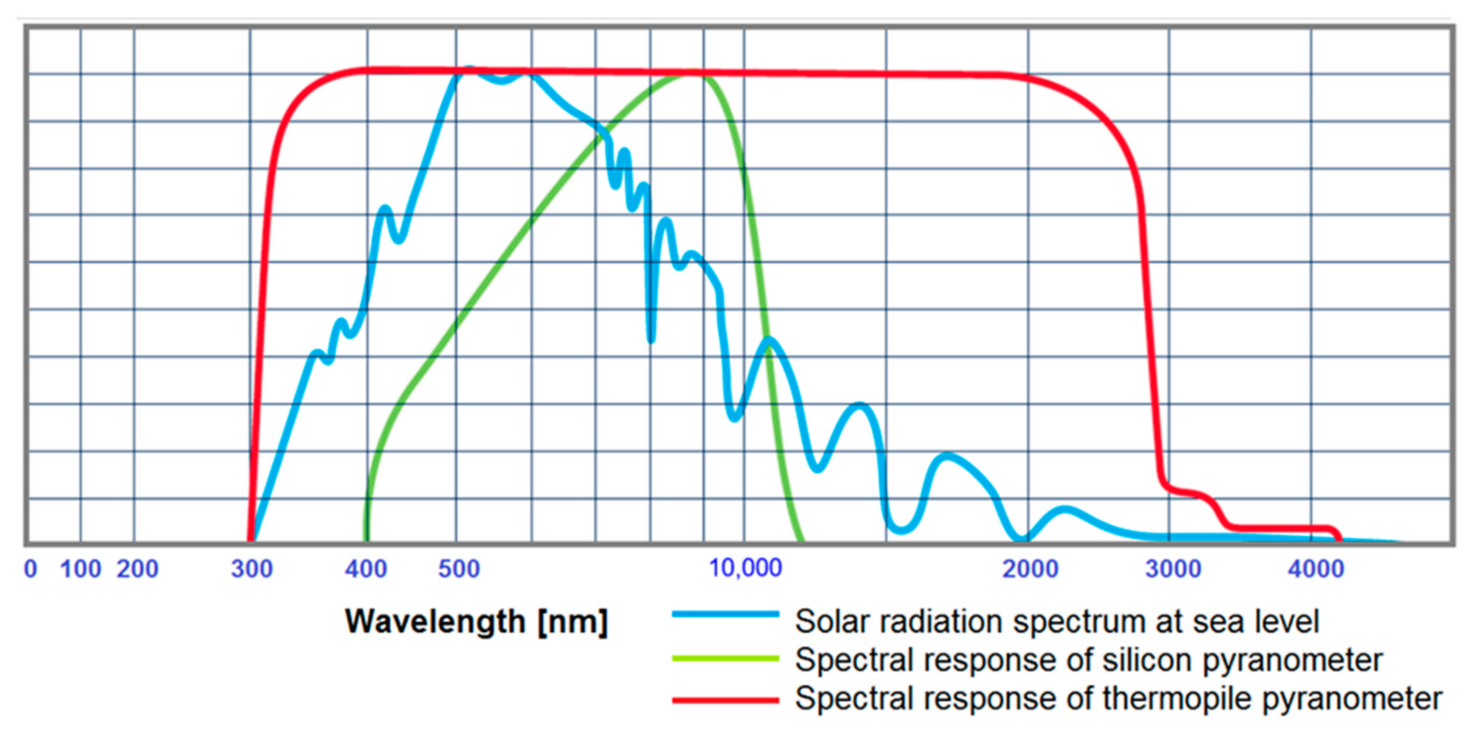
2.3.2. Spectral Response
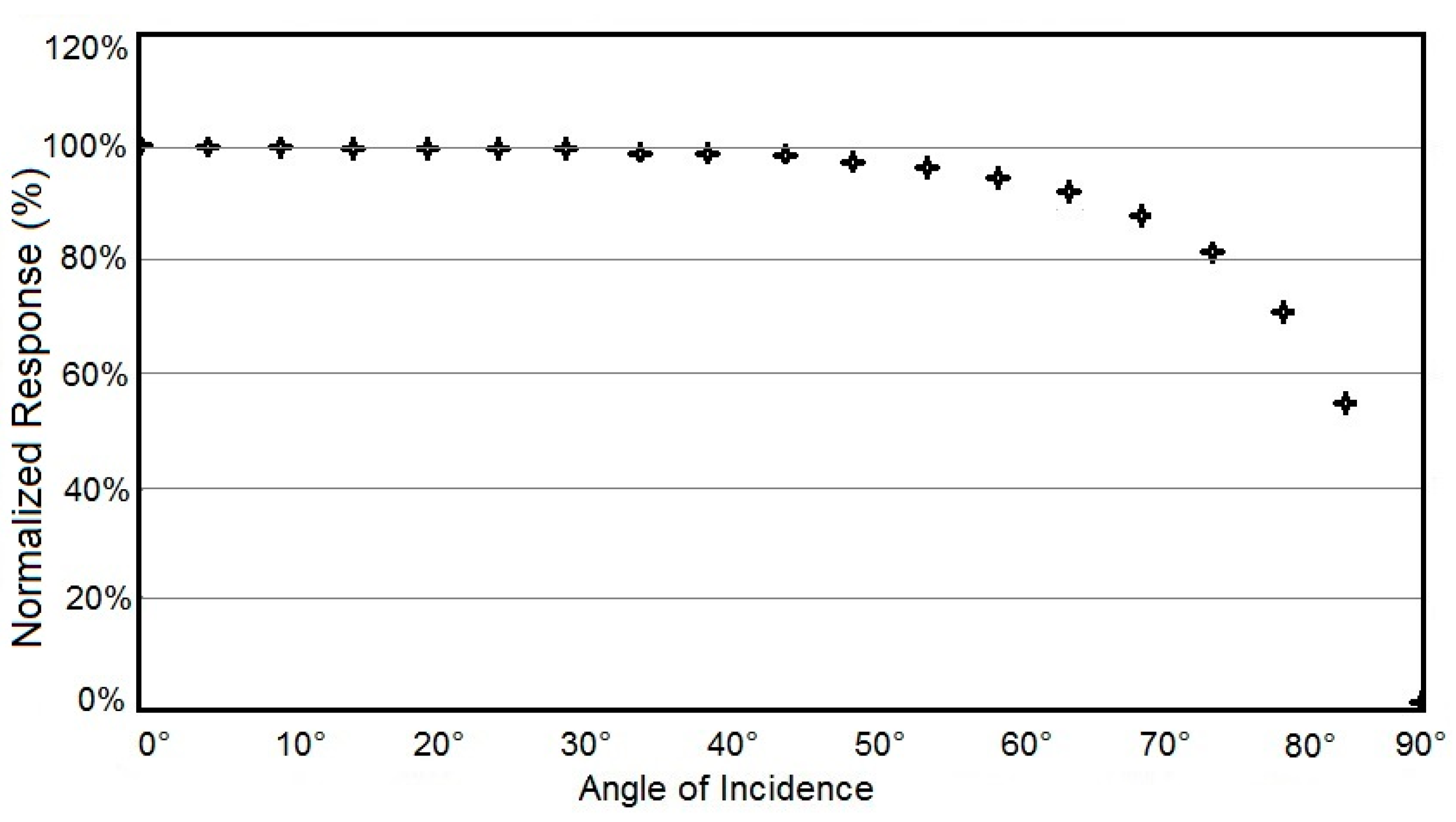
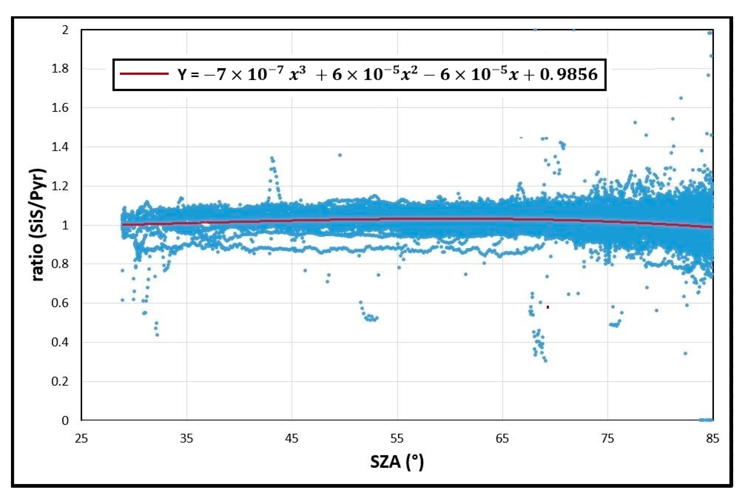
2.3.3. Angular Response
3. Methods
3.1. Measurement Site
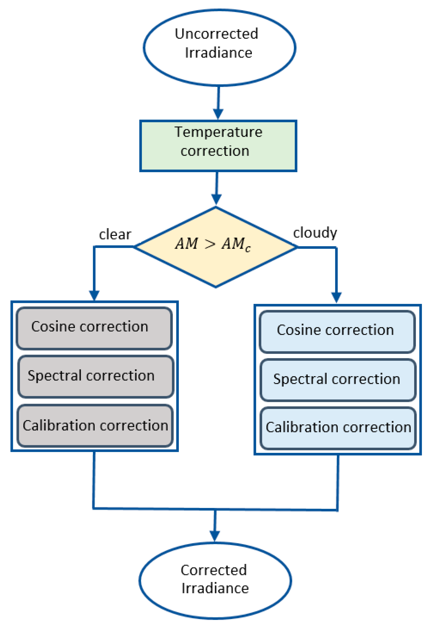
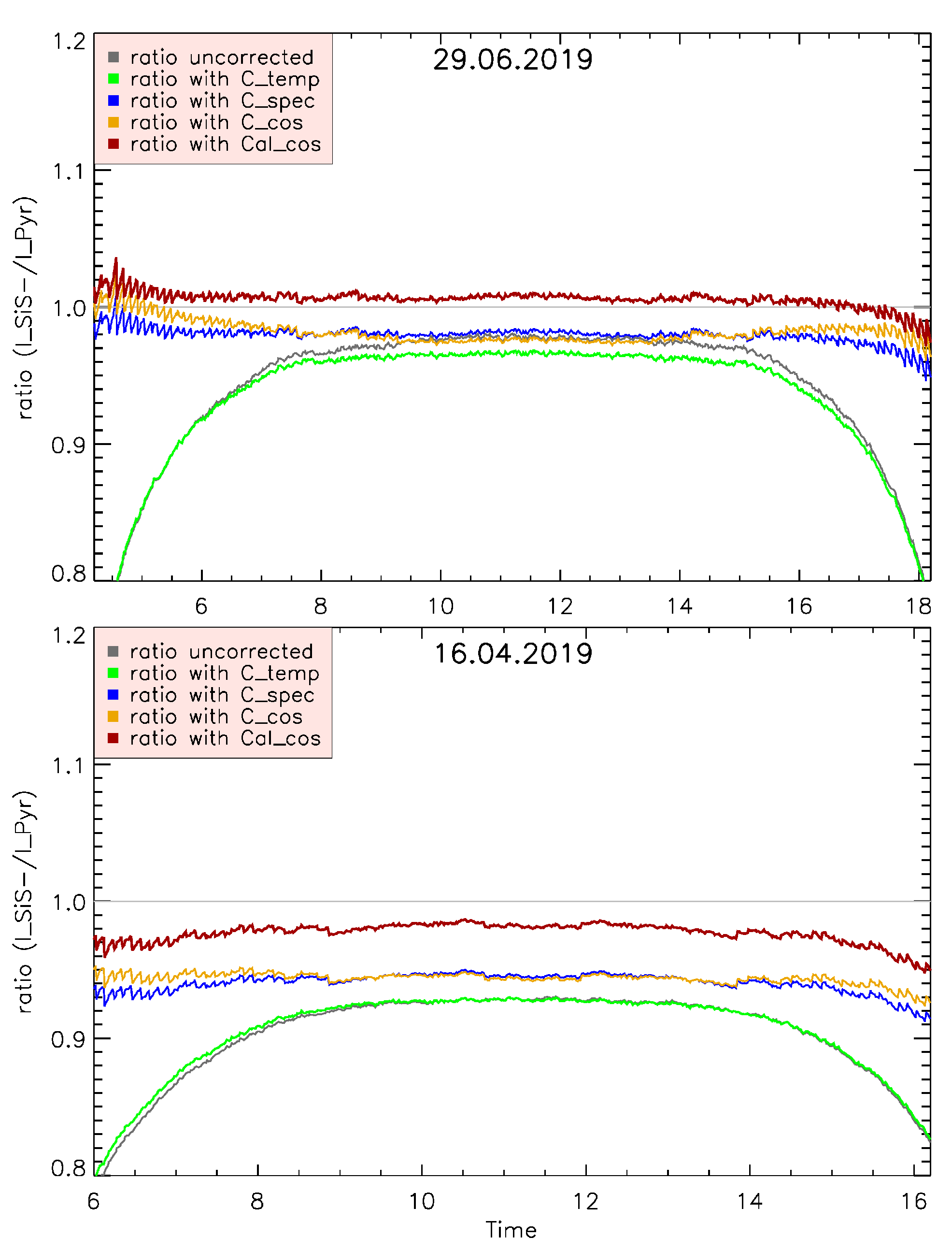
3.2. Correction Model
3.2.1. Temperature Correction ()
3.2.2. Cosine Correction ()
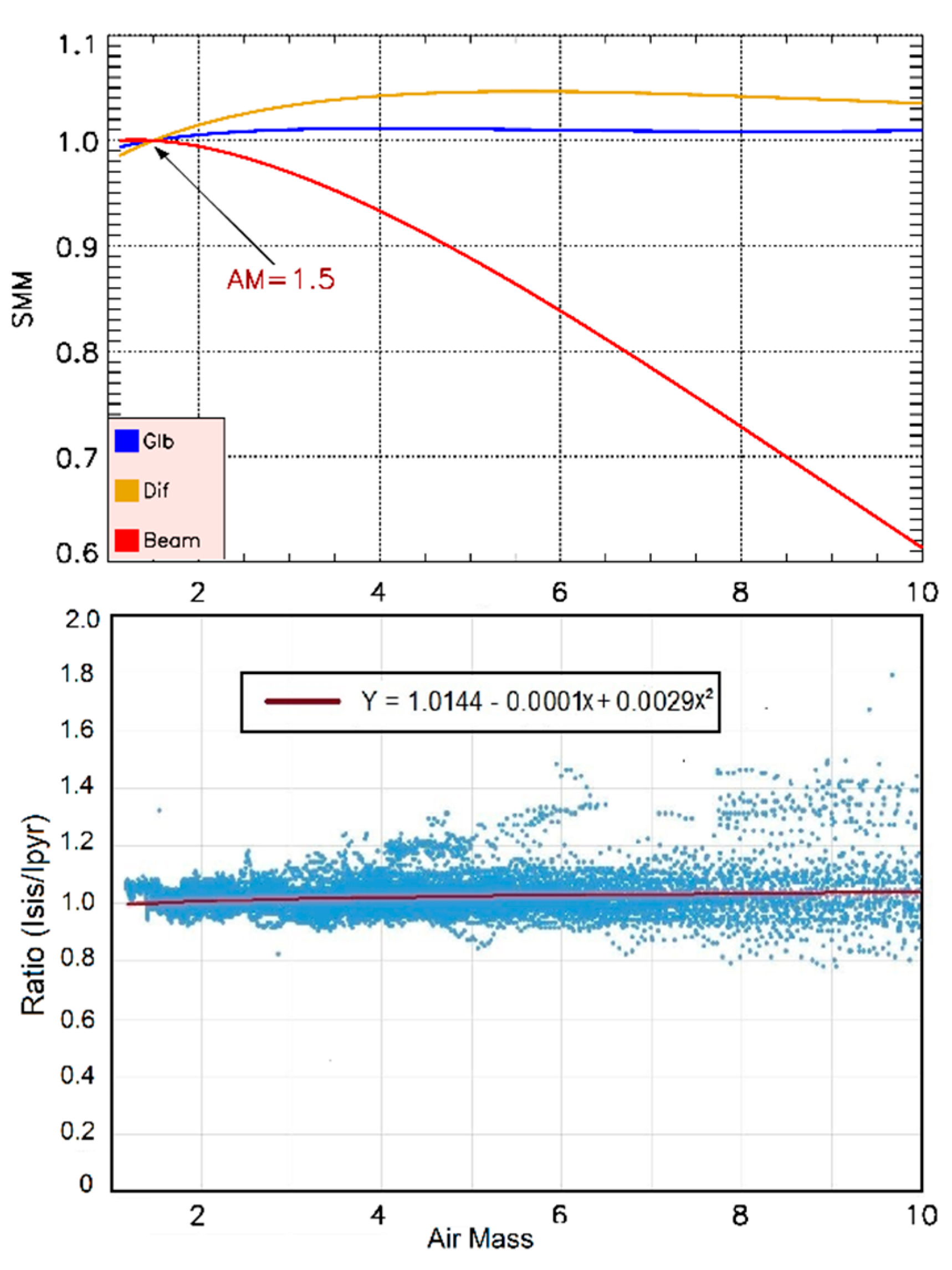
3.2.3. Spectral Mismatch Correction ()
3.2.4. Calibration Correction ()
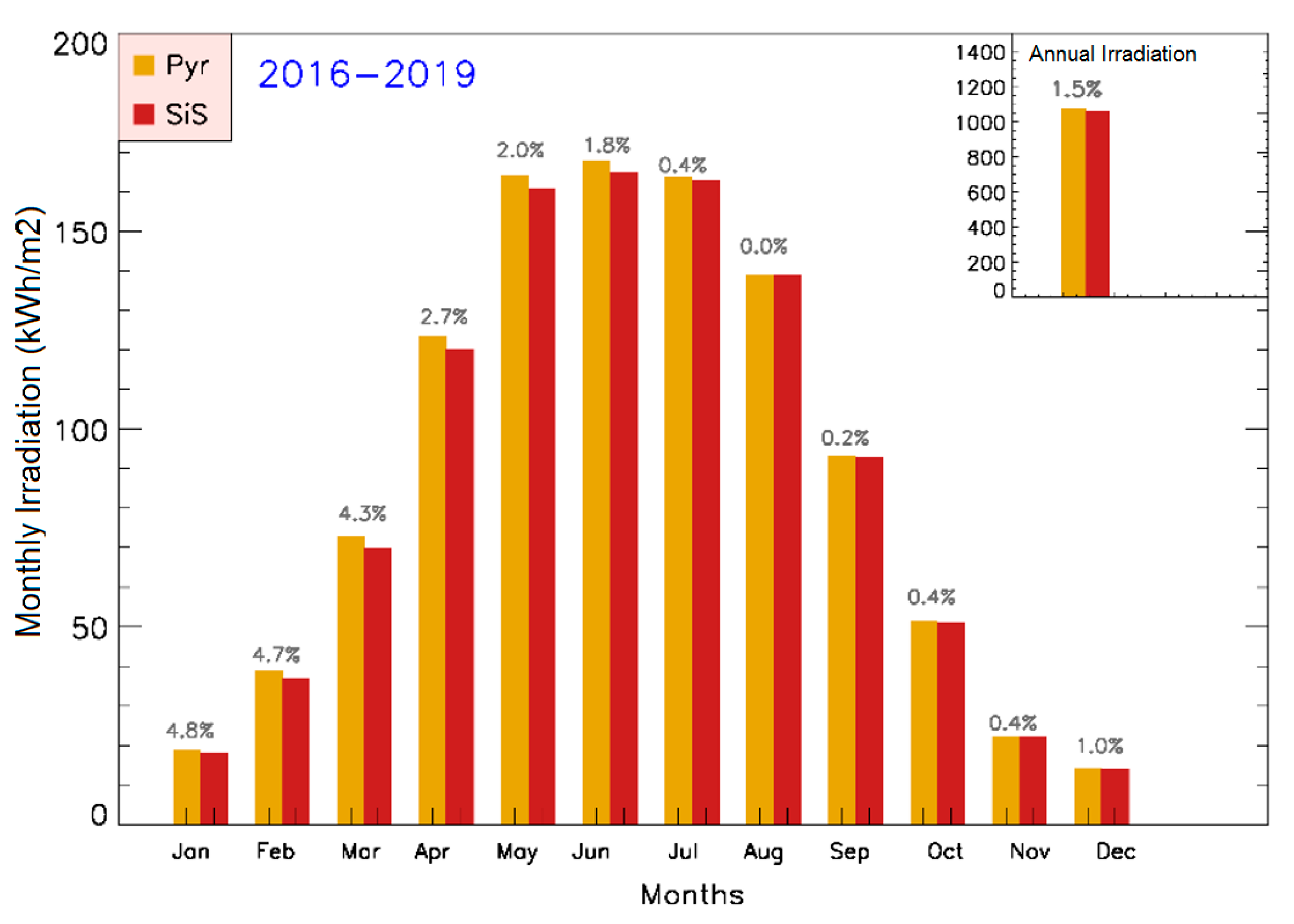
4. Results and Discussion
5. Conclusions
Author Contributions
Funding
Acknowledgments
Conflicts of Interest
Nomenclature
| GHI | Global Horizontal Irradiance |
| DHI | Diffuse Horizontal Irradiance |
| AM | Air Mass |
| Pyr | Thermopile Pyranometer |
| SiS | Silicon Sensor |
| SR | Spectral Response |
| Δ | difference between cell temperature and STC value (25 °C) |
| α | temperature coefficient |
| Clearness Index | |
| SZA | Solar Zenith Angle |
| λ | Wavelength of Irradiance |
| Tf | Temperature factor |
| MFF | Spectral Mismatch Factor |
| CosEr | Cosine error |
| Cf | Calibration factor |
| Temperature of Sensor | |
| E | Global Irradiance |
| Minimum Solar Zenith Angle | |
| Temperature correction | |
| Spectral correction | |
| Cosine correction | |
| Calibration correction | |
| Short circuit current |
References
- Wright, S. Second Law Analysis of the Earth System with a Radiative Model. Int. J. Thermodyn. 2002, 5, 57–65. [Google Scholar]
- El-Shirbeny, M.A.; Abdellatif, B. Reference evapotranspiration borders maps of Egypt based on kriging spatial statistics method. Int. J. Geomate 2017, 13, 37. [Google Scholar] [CrossRef]
- Spertino, F.; di Leo, P.; Cocina, V. Accurate measurements of solar irradiance for evaluation of photovoltaic power profiles. In Proceedings of the 2013 IEEE Grenoble Conference PowerTech, Powertech 2013, Grenoble, France, 16–20 June 2013. [Google Scholar]
- Pereira, G.M.S.; Stonoga, R.L.B.; Detzel, D.H.M.; Küster, K.K.; Neto, R.A.P.; Paschoalotto, L.A.C. Analysis and Evaluation of Gap Filling Procedures for Solar Radiation Data. In Proceedings of the 2018 IEEE 9th Power, Instrumentation and Measurement Meeting, EPIM 2018, Salto, Uruguay, 14–16 November 2018. [Google Scholar]
- IPCC. Climate Change 2007-The Physical Science Basis: Working Group I Contribution to the Fourth Assessment Report of the IPCC. Science 2007, 4, 8117. [Google Scholar]
- Kopp, G.; Lean, J.L. A new, lower value of total solar irradiance: Evidence and climate significance. Geophys. Res. Lett. 2011, 1, 38. [Google Scholar] [CrossRef]
- Paulescu, M.; Paulescu, E.; Gravila, P.; Badescu, V. Weather Modeling and Forecasting of PV Systems Operation. Green Energy Technol. 2013, 5, 232. [Google Scholar]
- Wilbert, S.; Geuder, N.; Schwandt, M.; Kraas, B.; Jessen, W.; Meyer, R.; Nouri, B. Best Practices for Solar Irradiance Measurements with Rotating Shadowband Irradiometers; International Energy Agency: Paris, France, 2015. [Google Scholar]
- Dunn, L.; Gostein, M.; Emery, K. Comparison of pyranometers vs. PV reference cells for evaluation of PV array performance. In Proceedings of the Conference Record of the IEEE Photovoltaic Specialists Conference, Austin, TX, USA, 3–8 June 2012. [Google Scholar]
- Meydbray, J.; Riley, E.; Dunn, L.; Emery, K.; Kurtz, S. Pyranometers and Reference Cells: Part 2: What Makes the Most Sense for PV Power Plants; National Renewable Energy Lab: Golden, CO, USA, 2012.
- Azouzoute, A.; Merrouni, A.A.; Bennouna, E.G.; Gennioui, A. Accuracy measurement of pyranometer vs reference cell for PV resource assessment. Energy Procedia 2019, 157, 1201–1209. [Google Scholar] [CrossRef]
- Alados-Arboledas, L.; Batlles, F.J.; Olmo, F.J. Solar radiation resource assessment by means of silicon cells. Sol. Energy 1995, 54, 183–191. [Google Scholar] [CrossRef]
- King, D.L.; Myers, D.R. Silicon-photodiode pyranometers: Operational characteristics, historical experiences, and new calibration procedures. In Proceedings of the Conference Record of the IEEE Photovoltaic Specialists Conference, Anaheim, CA, USA, 3 October 1997. [Google Scholar]
- Vignola, F. Removing systematic errors from rotating shadowband pyranometer data. In Proceedings of the American Solar Energy Society-Solar 2006: 35th ASES Annual Conf., 31st ASES National Passive Solar Conference, 1st ASES Policy and Marketing Conf., ASME Solar Energy Division Internationnal Solar Energy Conference, Denver, CO, USA, 13 July 2006. [Google Scholar]
- Geuder, N.; Pulvermüller, B.; Vorbrugg, O. Corrections for rotating shadowband pyranometers for solar resource assessment. In Proceedings of the Optical Modeling and Measurements for Solar Energy Systems II, San Diego, CA, USA, 11 September 2008. [Google Scholar]
- Forstinger, A. Physically based correction of systematic errors of Rotating Shadowband Irradiometers. Meteorol. Z. 2020. Available online: https://elib.dlr.de/121698/1/__ASFS01_Group_Literature_Database_SolarResearch.Data_PDF_Bachelorthesis_Forstinger-1058268416_Bachelorthesis_Forstinger.pdf (accessed on 21 March 2021). [CrossRef]
- Mubarak, R.; Hofmann, M.; Riechelmann, S.; Seckmeyer, G. Comparison of modelled and measured tilted solar irradiance for photovoltaic applications. Energies 2017, 10, 1688. [Google Scholar] [CrossRef]
- Mubarak, R.; Luiz, E.W.; Seckmeyer, G. Why PV modules should preferably no longer be oriented to the south in the near future. Energies 2019, 12, 4528. [Google Scholar] [CrossRef]
- International Organization for Standardization. ISO 9060: Solar Energy-Specification and Classification of Instruments for Measuring Hemispherical Solar and Direct Solar Radiation; International Organization for Standardization: Geneva, Switzerland, 1990. [Google Scholar]
- CMP11 Secondary Standard Pyranometer-Kipp & Zonen. Available online: https://www.kippzonen.com/Product/13/CMP11-Pyranometer#.YFdMeucxlaQ (accessed on 21 March 2021).
- Vignola, F.; Peterson, J.; Chiu, C.Y.; Dooraghi, M.; Sengupta, M.; Mavromatakis, F. Comparison of pyranometers and reference cells on fixed and one-Axis tracking surfaces. In Proceedings of the ASES SOLAR 2017-46th Annual National Solar Conference, Denver, CO, USA, 9–12 October 2017. [Google Scholar]
- Vignola, F.; Peterson, J.; Kessler, R.; Dooraghi, M.; Sengupta, M.; Mavromatakis, F. Evaluation of Photodiode-based Pyranometers and Reference Solar Cells on a Two-Axis Tracking System. In Proceedings of the 2018 IEEE 7th World Conference on Photovoltaic Energy Conversion, WCPEC 2018-A Joint Conference of 45th IEEE PVSC, 28th PVSEC and 34th EU PVSEC, Waikoloa, HI, USA, 10–15 June 2018. [Google Scholar]
- King, D.L.; Boyson, W.E.; Hansen, B.R. Improved Accuracy for Low-Cost Solar Irradiance Sensors; Sandia National Labs.: Albuquerque, NM, USA, 1997.
- Myers, D.R.; Emery, K.A.; Stoffel, T.L. Uncertainty estimates for global solar irradiance measurements used to evaluate PV device performance. Sol. Cells 1989, 27, 455–464. [Google Scholar] [CrossRef]
- Si Sensor: Ingenieurbüro Mencke & Tegtmeyer GmbH. Available online: https://www.imt-solar.com/solar-irradiance-sensors/si-sensor/ (accessed on 21 March 2021).
- Dutton, E.G.; Michalsky, J.J.; Stoffel, T.; Forgan, B.W.; Hickey, J.; Nelson, D.W.; Alberta, T.L.; Reda, I. Measurement of the broadband diffuse solar irradiance using current commercial instrumentation with a correction for thermal offset errors. J. Atmos. Ocean. Technol. 2001, 18, 297–314. [Google Scholar] [CrossRef]
- Reda, I.; Stoffel, T.; Myers, D. A method to calibrate a solar pyranometer for measuring reference diffuse irradiance. Sol. Energy 2003, 74, 103–112. [Google Scholar] [CrossRef]
- Michalsky, J.J.; Harrison, L.; LeBaron, B.A. Empirical radiometric correction of a silicon photodiode rotating shadowband pyranometer. Sol. Energy 1987, 39, 87–96. [Google Scholar] [CrossRef]
- Perraki, V.; Kounavis, P. Effect of temperature and radiation on the parameters of photovoltaic modules. J. Renew. Sustain. Energy 2016, 8, 013102. [Google Scholar] [CrossRef]
- Iqbal, M. An Introduction to Solar Radiation; Elsevier: Amsterdam, The Netherlands, 2012. [Google Scholar]
- Michalsky, J.J.; Harrison, L.C.; Berkheiser, W.E. Cosine response characteristics of some radiometric and photometric sensors. Sol. Energy 1995, 54, 397–402. [Google Scholar] [CrossRef]
- Zibordi, G.; Bulgarelli, B. Effects of cosine error in irradiance measurements from field ocean color radiometers. Appl. Opt. 2007, 46, 5529–5538. [Google Scholar] [CrossRef] [PubMed]
- Cordero, R.R.; Seckmeyer, G.; Labbe, F. Cosine error influence on ground-based spectral UV irradiance measurements. Metrologia 2008, 45, 406. [Google Scholar] [CrossRef]
- Kipp, Z. Solar Radiation Measurements for Solar Energy Applications. Available online: file:///C:/Users/MDPI/AppData/Local/Temp/KippZonen_Solar_Energy_Guide-1.pdf (accessed on 21 March 2021).
- Wetter und Klima-Deutscher Wetterdienst-Our Services-Maps of Global Radiation, Monthly and Annual Sum. Available online: https://www.dwd.de/EN/ourservices/solarenergy/maps_globalradiation_sum.html?nn=495490 (accessed on 1 April 2021).
- Elminir, H.; Benda, V.; Tousek, J. Effects of solar irradiation conditions and other factors on the outdoor performance of photovoltaic modules. J. Electr. Eng. 2001, 52, 125–133. [Google Scholar]
- Shukla, A.K. Experimental Methods in the Physical Sciences; Elsevier: Amsterdam, The Netherlands, 2009. [Google Scholar]
- Huang, X.; Quan, C.; Kng, J. Comparison of two methods for short circuit current measurement of large size solar cell. In Proceedings of the International Conference on Optical and Photonic Engineering (icOPEN2015), Singapore, 17 July 2015; p. 95242A. [Google Scholar]
- Stark, C.; Theristis, M. The impact of atmospheric parameters on the spectral performance of multiple photovoltaic technologies. In Proceedings of the 2015 IEEE 42nd Photovoltaic Specialist Conference (PVSC), New Orleans, LA, USA, 14–19 June 2015; pp. 1–5. [Google Scholar]
- Kasten, F.; Young, A.T. Revised optical air mass tables and approximation formula. Appl. Opt. 1989, 28, 4735–4738. [Google Scholar] [CrossRef] [PubMed]
- Mayer, B.; Kylling, A. Technical Note: The libRadtran Software Package for Radiative Transfer Calculations-Description and Examples of Use. Atmos. Chem. Phys. 2005, 5, 1855–1877. [Google Scholar] [CrossRef]
- Amillo, A.M.G.; Huld, T.; Vourlioti, P.; Müller, R.; Norton, M. Application of satellite-based spectrally-resolved solar radiation data to PV performance studies. Energies 2015, 8, 3455–3488. [Google Scholar] [CrossRef]


| Specifications | CMP11 | Si-mV-85 |
|---|---|---|
| Spectral sensitivity range (nm) | 285–2800 | 360–1200 |
| Response time (s) | <5 | <0.001 |
| Offset (W/m2) | <2 | 0 |
| Temperature dependence (−20–40 °C) (%) | <1 | 0.2 |
| Uncertainty (W/m2) | <5 | ±5 |
| Non-linearity (100 to 1000 W/m2) (%) | <0.2 | ±0.1 |
| Angular response (% up to 80° SZA) | <1 | <30 |
| SZA Range | Clearness Index |
|---|---|
| 40° > SZA | > 0.50 |
| 40° < SZA < 50° | > 0.40 |
| 50° < SZA < 55° | > 0.30 |
| 55° < SZA < 60° | > 0.27 |
| 60° < SZA < 65° | > 0.20 |
| 65° < SZA < 70° | > 0.15 |
| 70° < SZA < 75° | > 0.10 |
| 75° < SZA < 80° | > 0.05 |
| 80° < SZA < 82° | > 0.04 |
| 82° < SZA < 84° | > 0.02 |
| 84° < SZA < 85° | > 0.015 |
| Ucalb | |||||
|---|---|---|---|---|---|
| rRMSD (%) | 10.6 | 10.8 | 7.5 | 7.6 | 5.4 |
| rMAD (%) | 7.4 | 7.6 | 4.7 | 4.8 | 2.5 |
Publisher’s Note: MDPI stays neutral with regard to jurisdictional claims in published maps and institutional affiliations. |
© 2021 by the authors. Licensee MDPI, Basel, Switzerland. This article is an open access article distributed under the terms and conditions of the Creative Commons Attribution (CC BY) license (https://creativecommons.org/licenses/by/4.0/).
Share and Cite
Mubarak, R.; Schilke, H.; Seckmeyer, G. Improving the Irradiance Data Measured by Silicon-Based Sensors. Energies 2021, 14, 2766. https://doi.org/10.3390/en14102766
Mubarak R, Schilke H, Seckmeyer G. Improving the Irradiance Data Measured by Silicon-Based Sensors. Energies. 2021; 14(10):2766. https://doi.org/10.3390/en14102766
Chicago/Turabian StyleMubarak, Riyad, Holger Schilke, and Gunther Seckmeyer. 2021. "Improving the Irradiance Data Measured by Silicon-Based Sensors" Energies 14, no. 10: 2766. https://doi.org/10.3390/en14102766
APA StyleMubarak, R., Schilke, H., & Seckmeyer, G. (2021). Improving the Irradiance Data Measured by Silicon-Based Sensors. Energies, 14(10), 2766. https://doi.org/10.3390/en14102766