Abstract
Thermoacoustic devices are the systems which use acoustic power to transport heat through a stack in a resonance tube. The stack is one of the most important parts of the thermoacoustic systems. It can have different geometries, like parallel plates, circular pores, or pin arrays. However, the fabrication of stacks with regular geometries is sometimes impractical due to material and assembly costs. These problems can be solved by using stack fabricated with random and easily accessible porous materials. In this paper an experimental investigation on the thermoacoustic effect in easily accessible porous materials is presented. The measurements with the stacks were made in a standing wave device filled with air at atmospheric pressure. The reported results confirm that some of the materials with high porosity can be an alternative to a traditional stack geometries and materials.
1. Introduction
Thermoacoustics is a multidisciplinary science dealing with the conversion between the acoustic energy and thermal energy. The expression “thermoacoustic” was first proposed in the 1970s by N. Rott, who derived a linear theory of thermoacoustics [1]. Nevertheless, the first observations of the thermoacoustic effect can be dated back more than 200 years ago, when in 1777 B. Higgins discovered the relationship between the acoustic oscillations excited by the hydrogen flame and the placement of this hydrogen flame inside a large tube [2]. In 1850, Sondhauss experimentally studied the phenomenon of heat-generated sound observed for centuries by the glassblowers, when blowing a hot bulb at the end of a cold narrow tube [3]. Only nine years later, in 1859, Rijke modified the Higgin’s tube and placed a heated wire screen in the lower part of an open-ended tube, which led to strong acoustic oscillations [4]. An important improvement of Sondhauss’ tube was done in 1962 by Carter and co-works. They enhanced sound generated from tube by placing inside it a new structure—stack [5]. The idea of Carter et al., further developed by Feldman, led to the construction of the first thermoacoustic engine, which produced 27 W of acoustic power from 600 W of heat [6]. It was one of the most crucial steps in the progress of modern thermoacoustic technology, which began a lot of theoretical and experimental research on the thermoacoustic phenomena and the thermoacoustic devices.
Thermoacoustic devices rely on the thermal interactions between the compressible fluid undergoing an acoustic oscillation and the porous structure that is placed in the resonator. As the fluid oscillates in the porous structure, it experiences changes in pressure, displacement, and temperature. On the one hand, the temperature changes come from adiabatic expansion and compression by acoustic wave, on the other, they are a result of the heat transfer between the fluid and the porous structure. There are two main type of porous medium used to exchange heat with the working fluid—stack and regenerator. In the stack, the hydraulic radius of a typical pore is greater than the thermal penetration depth , defined as a distance across which heat can diffuse through the gas in a time that is related to the acoustic period of the acoustic oscillation . Because in the stack , the portions of the fluid that are close to the solid are simply compressed and expanded isothermally by acoustic wave, while the portions of the fluid at distances of a few thermal penetration depth are compressed and expanded adiabatically. However, in the stack are also fluid parcels that are about thermal penetration depth from the solid. These parcels have sufficient thermal contact to exchange some heat with the porous material and as well insufficient thermal contact to introduce a time shift between the temperature and the pressure oscillation. This imperfect thermal contact between the stack and the fluid is necessary for the heat pump process. The operation of the thermoacoustic devices with the stack requires pressure and displacement of a fluid parcel in the phase, thus these devices are also called standing-wave engines or refrigerators [7]. Whether the thermoacoustic device works as engine or refrigerator (heat pump) depends on the relative phasing of motion and the heat transfer direction. The engine converts thermal energy into acoustic energy, while the refrigerator utilizes acoustic energy to transport heat from a low-temperature source to a high-temperature source. A more detailed explanation of the operating principles of the thermoacoustic devices is available in Swift’s review article [5].
In the recent years, thermoacoustic devices have been receiving growing interest in research for their many advantages, such as using environmentally friendly working fluids, possibility of utilizing renewable energy sources, having few moving components, simple construction, and high reliability. For example, the main components of a typical thermoacoustic refrigerator are a stack, an acoustic driver, in most cases an electrodynamic loudspeaker and the heat exchangers for high-temperature and low-temperature heat source (Figure 1). However, wide application of thermoacoustic devices in the industry is still limited due to poor efficiency, which remains one of the problems facing this relative new technology. Therefore, thermoacoustic refrigerators and engines have been extensively studied experimentally as well as theoretically.
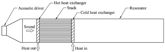
Figure 1.
Schematic illustration of the thermoacoustic refrigerator with standing wave.
Most of the current investigations for thermoacoustic devices with standing wave have been done on the stack, which especially concern stack geometry [8,9,10,11], position [12,13,14], and length [15,16,17]. The stack can be made of spiral plate, parallel plate, circular pores, pin arrays, or triangular pores. The two first types are the most often used, studied and analyzed [18]. Tijani et al. [19] performed a quantitative experimental research into the effect of the plate spacing in the stack on the thermoacoustic effect in the thermoacoustic refrigerator working with the operating frequency of 400 Hz and with the helium under the pressure of 10 bar. The researchers found out that the distance between the plates of about was optimum for the cooling power, gave the highest performance, and provided the lowest temperature. Similar results concerning temperature dependence, but for significantly different configuration of the refrigerator, which worked with air at atmospheric pressure and frequency of 107 an 86 Hz, were also observed by Setiawan et al. [20]. The impact on the temperature difference across the stack in other stack geometries like spiral, circular pore, and pin arrays was studied experimentally by Wantha [21]. His thermoacoustic refrigeration system worked with constant frequency of 720 Hz and used helium as the working fluid at different pressure, from 1 to 4 bar. The results showed that the temperature of the cold end of the pin array stack decreases more than of the spiral and the circular pore stack. Tasnim et al. [22] compared in turn the influence of stack properties with regular and random porous media on the performance of the thermoacoustic heat pump. Their device worked with the frequency of about 350 Hz and was filled with air at atmospheric pressure. The results showed, for example, that temperature difference generated across the RVC (reticulated vitreous carbon) stack increases as the porosity increases, reaches maximum value and then decreases when porosity increases further; however, in all cases the temperature differences for RVC stacks were lower than for stacks with regular geometries. The stacks with irregular geometries such as stainless-steel wool, copper scourers, and carbon foam were also investigated by Yaha et al. [23] in a standing wave thermoacoustic refrigerator. The apparatus consisted of a half-wavelength resonator filled with air at atmospheric pressure, which operated at a fundamental resonance frequency of 72 Hz. Among the irregular materials, the steel wool stacks achieved the maximum cooling power, the lowest temperature and the highest COPR, however, the same as in [22], this type of stack geometry showed the worse performance in comparison to parallel stacks. The experimental research on an RVC as a stack material was performed by Adeff et al. in a thermoacoustic prime mover filled with pure neon, as well as in a thermoacoustic refrigerator with helium as the working fluid [24]. In both cases, the efficiencies depended on RVC porosities and were lower than efficiencies of parallel plate stacks. Nevertheless, Adeff et al. recognized the RVC as a low cost and easy to fabricate material that can be used in the thermoacoustic devices.
Many analytical and numerical studies have been done on the stack as well. Ishikawa et al. [25] numerically examined the flow and the energy fields in the stack as the functions of the drive ratio and the plate spacing. Marx et al. [26] calculated numerically the temperature difference between the stack extremities and found that at higher Mach number some deviations between numerical results and the linear theory predictions occur. An effect of the blockage ratio and the acoustic pressure amplitude on the energy flow and entropy generation were modeled by Zoontjens et al. [27]. The entropy generation inside the porous structure modeled as a parallel-plate stack was also examined by Piccolo [28]. Based on a simplified two-dimensional computational method it was shown that entropy generation can be used effectively as a design criterion for optimizing simultaneously the stack position, stack length and the plate spacing. A bulk porous media representing stack in a thermoacoustic systems, such as RVC foams, were analytically studied by Tasnim et al. [29]. Bhatti et al. [30], in turn, numerically investigated the multi-layered stacks, that are composed of different materials. Their results showed that multi-layered stacks consume less energy and provide higher COP than their homogeneous counterparts.
Most of experimental and analytical or numerical works in thermoacoustics deal with stacks that have regular geometries, especially parallel plates configuration. However, the fabrication of parallel plates and other regular stack geometries is sometimes difficult, impractical, and time-consuming. These problems in some cases can be avoided by using stack that are made of random porous materials. There is a wide range of porous materials that are low-cost and readily available and can be a good candidate for thermoacoustic stack applications. Most of them have not been studied extensively and no experimental data is available. In this paper an experimental investigation on the thermoacoustic effect in easily accessible porous materials, from which some is not reported in literature, is presented. The employed method is based on a temperature difference created across the thermoacoustic stack. As in most similar research, the number of parameters in the experiment is limited. The results are thought to be helpful in optimal design, development and improvement of the components of the thermoacoustic refrigerators, heat pumps, or prime movers.
2. Experimental Apparatus and Instrumentation
Figure 2 illustrates the arrangement of the experimental apparatus. It consists of the loudspeaker with nominal impedance of 4 Ω and continuous power handling of 200 W RMS, which constitutes the acoustic wave source. The loudspeaker is excited by amplifier fed with a sinusoidal signal, provided by the software installed on the computer. The resonator is built with segments of straight stainless-steel tube with inner diameter 84.9 mm, fixed to each other by screwing. The length of the resonator can be adjusted to the operating frequency by mounting an additional segment of the resonance tube. The device is not equipped in the heat exchangers. The heat flow is maintained from the pores themselves. Therefore, the stack will cool at one side—named as cold end, where heat is removed and will heat at the other side—named as hot end, where heat is reversed. The thermal performance of the stack is thus measured in terms of temperature difference generated across the stack. The set-up for the experimental investigation for the frequency of 300 Hz is indicated in Figure 3.
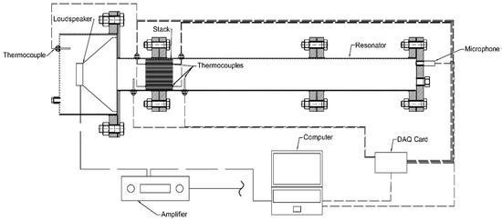
Figure 2.
Schematic illustration of the experimental apparatus.
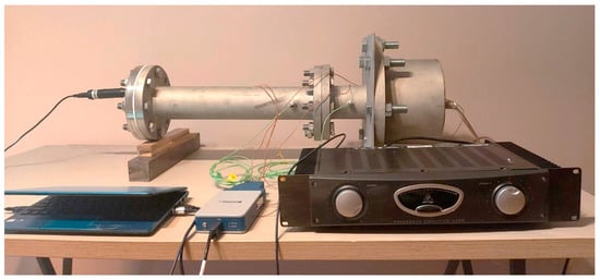
Figure 3.
Photo of the experimental apparatus for the frequency of 300 Hz.
The LabVIEW 2019 software with sound and vibration toolkit was used for generation sinusoidal signal and processing signals from the thermocouples and the microphone. The temperatures on both ends of the stack were measured with two T-type thermocouples attached in different places. The temperature difference created across the stack was then calculated as
where and are the temperatures at one end of the stack, while and at other (Figure 4). The K-type thermocouples were in turn used to control the temperature of the stack and the loudspeaker surroundings. All temperatures data from thermocouple were acquired by the data acquisition card NI 9212. The acoustic frequency and sound pressure level were measured with a condenser microphone UMM-6 mounted at the closed end of the resonance tube (Figure 2 and Figure 3).
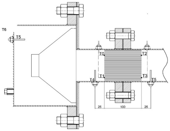
Figure 4.
Schematic illustration showing thermocouples names and locations.
In order to investigate the thermoacoustic effect in low-cost and readily available stacks a several types of different porous materials like polyurethane sponge, steel wool with gradation 1 and 000, viscose sponge and soft and sharp abrasive fabric were selected. All the materials are readily available, e.g., in a DIY store. The porosities of the stacks with these materials were estimated based on hydrostatic weighing in the water. The specifications of all stacks are summarized in Table 1. The photos of the stack are presented in Figure 5.

Table 1.
Specifications of the stacks.
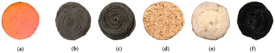
Figure 5.
Photos of stacks: (a) polyurethane sponge, (b) steel wool—gradation 1, (c) steel wool—gradation 000, (d) viscose sponge, (e) soft abrasive fabric, (f) sharp abrasive fabric.
Every stack from Table 1 was investigated under three different frequencies: 200, 250, and 300 Hz with the resonator length equalled respectively to 870, 700, and 580 mm, which corresponded to the half-length of acoustic wave for these frequencies at measuring conditions. In every measurement, the stack center was located 150 mm from the sound source and sound pressure level, controlled by the microphone, was kept at 70 dB. For each experiment, the data was read for 600 s. The working fluid was air at atmospheric pressure.
3. Results and Discussion
The temperature differences between the stack ends for stacks made of different porous materials are presented in Figure 6. As can be seen, the temperature difference depends on the porosity of the materials, as well as on the operating frequency. The highest temperature difference, nearly 16 K was achieved for stack made of steel wool with gradation 000 at the frequency of 200 Hz, while the lowest temperature difference about 0.5 K was obtained for stack made of viscose sponge at frequency of 300 Hz. In all measurements, the lowest temperature difference was achieved at this frequency. Analyzing the temperature differences generated between the stack ends at each frequency it can be easily observed that for 200 Hz the temperature difference increases with the increase of the material porosity, whereas for 250 Hz and 300 Hz reaches maximum for soft abrasive fabric and then starts to decrease. It is worth pointing out that the porosity of the materials presented in Table 1 refers only to an average packing density of the materials and does not describe the sizes of the pores. As it was mentioned above, the successful operation of the stack requires imperfect thermal contact between the stack material and the working fluid, which is obtained for the pore size of a few thermal penetration depth. The thermal penetration depth in turn depends on the acoustic frequency, thus the temperature difference at 200 and 300 Hz for soft abrasive fabric is higher than for steel wool as it can have bigger pores, which better match to the frequency. On the other hand, for materials with lower porosity, the increase in the blockage area reduces the heat flow between the stack ends. The same explanation applies to the differences in the results for the same materials working at different frequencies. The pore size in relation to thermal penetration depth causes that the temperature difference for one frequency is higher than for other. However, the investigation analyzed the stacks only with the same length—10 cm (Table 1). The length of the stack determines how many thermoacoustic interactions can occur across the stack. The longer stacks lead to more thermoacoustic interactions (more fluid parcels taking part in thermoacoustic effect), which should result in higher temperature difference between the stack ends. However, longer stacks also lead to more viscous effects, which reduce the heat transfer across the stack. This dependence is also one of the reasons of the differences in the results for the stack made of the same materials but working at different frequencies. The stacks that are closer to the optimal length at a given frequency and given porosity achieve higher temperature difference.
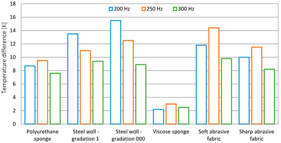
Figure 6.
Temperature differences between stack ends for different porous materials.
The Figure 7, Figure 8 and Figure 9 present the temperatures profiles for the stacks made of steel wool with gradation 1, viscose sponge and soft abrasive fabric at frequency of 250 Hz, respectively. In the figures the T0 and T1 are the temperatures at the stack end that is closer to the sound source, the T2 and T3 are the temperature at the other end of the stack, the T4 is the temperature of the stack surrounding closer to the sound source, the T5 is the temperature of the surrounding on the other side of the stack and T6 is the temperature of loudspeaker surrounding (Figure 4). The temperature evolution for each of the stack is slightly different than what follows from the porosity and heat conductivity of the materials used in the experiment. In all cases, the heat starts to flow out from one end of the stack into the other as the acoustic power is supplied. Due to this heat flow caused by the thermoacoustic effect in the early stage of the measurement the temperature of the one end of the stack that is closer to the sound source increases, the temperature of the other end of the stack decreases. In the late stage of the measurement the increasing role of a diffusive heat flux trough the stack material is observed. For the stack made of steel wool (Figure 7) the highest increase in the temperature difference generated between the stack ends is noticeable for 60 s. Then, due to heat conduction trough material in the direction against thermoacoustic heat transport, the temperature of the cold end of the stack started to increase, and at the end of measurement (after 600 s) it almost reached the initial temperature. In the case of the stack made of soft abrasive fabric, the increase of the temperature of the cold end of stack also occurs (Figure 9). However, the increase is much lower than for the steel wool stack—about 1 K during 600 s, because the soft abrasive fabric is characterized by lower thermal conductivity. For the stack made of viscose sponge the temperature decrease of the cold end of the stack is very low and the temperature difference across the stack ends results mainly from the dissipation of acoustic energy (Figure 8). The influence of thermoacoustic effect on the temperature difference for this stack is minimal. For the stacks made of steel wool and soft abrasive fabric a higher increase at the hot side of the stack is also observed than the temperature decreases at the cold side of the stack. The acoustic power absorbed by the gas near the stack shows up as dissipative heat (through viscous and thermal processes) which is accumulated at the hot side of the stack. The experimental device has no heat exchangers and no heat is removed, thus a higher temperature increase at the hot side of the stack is observed.
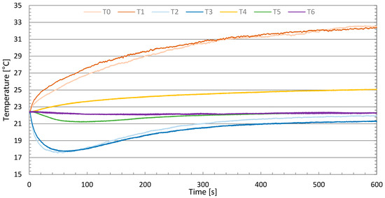
Figure 7.
Temperatures profiles for stack made of steel wool—gradation 1.
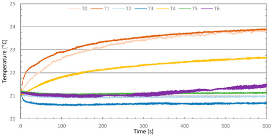
Figure 8.
Temperatures profiles for stack made of viscose sponge.
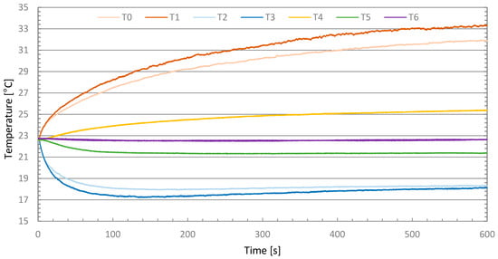
Figure 9.
Temperatures profiles for stack made of soft abrasive fabric.
The temperatures measurements for the stack surroundings (T4 and T5 lines) show an axial heat transfer at the stack extremities. After the rapid increase of the stack hot end temperature and decrease of the stack cold end temperature a convective heat flux from the outer surface of the stack to surroundings appears. On the one side, heat flows from the gas to the stack, thereby decreasing the temperature of gas, on the other side heat flows from the stack to the gas causing the increase of the temperature of the hot end surrounding. Further temperatures changes in the stack surroundings result from the temperatures changes of the stack ends. For stack made of viscose sponge the temperatures evolutions of the stack hot end and surrounding of the stack hot end after about 100 s are almost identical since the increase of the stack end temperature is mostly due to dissipation of acoustic power on the stack surface.
4. Conclusions
An experimental study on the temperature difference generated across the thermoacoustic stacks made of easily accessible porous materials has been successfully done. Seven different stacks with the same shape have been built and tested to compare the influence of porosity. The results indicate a better performance in terms of temperature difference for stack characterized by higher porosity. The highest temperature difference was achieved for the stack made of steel wool with a gradation 000 at the frequency of 200 Hz, while the lowest was for viscose sponge also at 200 Hz. The dependence of porosity on the temperature difference across the stack that comes from experiments is consistent with the results from other similar works, cited in this article. The same applies to the influence of heat conductivity. High heat conductivity led to quick increase of the temperature of the cold end of the stack. When the device in not equipped in the heat exchangers, like in the measurements, the increase of the temperature difference is partly due to the dissipation of the acoustic energy on the surface of the stack.
The novelty of this investigation in relation to similar ones is that it used materials that are really low cost and easily accessible as stack materials. The construction of the stacks with these materials is simple and no time-consuming. Such a solution can be especially recommended for the inexpensive thermoacoustic refrigerator designed for the demonstration of the basic physical principles of thermoacoustic phenomena.
Author Contributions
Experimental investigation: J.K., analysis: J.K. and A.R., writing—original draft preparation: J.K., writing—review and editing: J.K. and A.R. All authors have read and agreed to the published version of the manuscript.
Funding
This research received no external funding.
Institutional Review Board Statement
Not applicable.
Informed Consent Statement
“Not applicable” for studies not involving humans.
Data Availability Statement
Please refer to suggested Data Availability Statements in section “MDPI Research Data Policies” at https://www.mdpi.com/ethics.
Conflicts of Interest
The authors declare that they have no conflict of interest.
References
- Rott, N. Thermoacoustics. Adv. Appl. Mech. 1980, 20, 135–175. [Google Scholar]
- Putnam, A.A.; Dennis, W.R. Survey of Organ-Pipe Oscillations in Combustion Systems. J. Acoust. Soc. Am. 1956, 28, 246–259. [Google Scholar] [CrossRef]
- Sondhauss, C. Ueber die Schallschwingungen der Luft in erhitzten Glasröhren und in gedeckten Pfeifen von ungleicher Weite. Ann. Phys. 1850, 155, 1–34. [Google Scholar] [CrossRef]
- Bisio, G.; Rubatto, G. Sondhauss and Rijke oscillations–thermodynamic analysis, possible applications and analogies. Energy 1999, 24, 117–131. [Google Scholar] [CrossRef]
- Swift, G.W. Thermoacoustic engines. J. Acoust. Soc. Am. 1988, 84, 1145–1180. [Google Scholar] [CrossRef]
- Feldman, K.T. A Study of Heat Generated Pressure Oscillations in a Closed End Pipe. Ph.D. Thesis, University of Missouri, Columbia, MO, USA, 1966. [Google Scholar]
- Garrett, S.L. Thermoacoustic engines and refrigerators. AIP Conf. Proc. 2004, 1440, 9–22. [Google Scholar]
- Auriemma, F.; Di Gulio, E.; Napolitano, M.; Dragonetti, R. Porous Cores in Small Thermoacoustic Devices for Building Applications. Energies 2020, 13, 2941. [Google Scholar] [CrossRef]
- Hariharan, N.M.; Sivashanmugam, P.; Kasthurirengan, S. Influence of stack geometry and resonator length on the performance of thermoacoustic engine. Appl. Acoust. 2012, 73, 1052–1058. [Google Scholar] [CrossRef]
- Bosel, J.; Trepp, C.; Fourie, J.G. An alternative stack arrangement for thermoacoustic heat pumps and refrigerators. J. Acoust. Soc. Am. 1999, 106, 707–715. [Google Scholar] [CrossRef]
- Akhavanbazaz, M.; Siddiqui, M.K.; Bhat, R.B. The impact of gas blockage on the performance of a thermoacoustic refrigerator. Exp. Therm. Fluid Sci. 2007, 32, 231–239. [Google Scholar] [CrossRef]
- Kajurek, J.; Rusowicz, A.; Grzebielec, A. The Influence of Stack Position and Acoustic Frequency on the Performance of Thermoacoustic Refrigerator with the Standing Wave. Arch. Thermodyn. 2017, 38, 89–107. [Google Scholar] [CrossRef]
- Kim, Y.T.; Kim, M.G.; Suh, S.J. Optimum Positions of a Stack in a Thermoacoustic Heat Pump. J. Korean Phys. Soc. 2000, 36, 279–286. [Google Scholar]
- Setiawan, I.; Setia-Utomo, A.B. The Influence of the Length and Position of the Stack on the Performance of a Thermoacoustic Refrigerator. Master’s Thesis, Gadjah Mada Univesrity, Yogyakarta, Indonesia, 2013. [Google Scholar]
- Alcock, A.C.; Tartibu, L.K.; Jen, T.C. Experimental investigation of an adjustable thermoacoustically-driven thermoacoustic refrigerator. Int. J. Refrig. 2018, 94, 71–86. [Google Scholar] [CrossRef]
- Tartibu, L.K. Maximum cooling and maximum efficiency of thermoacoustic refrigerators. Heat Mass Transf. 2016, 52, 95–102. [Google Scholar] [CrossRef]
- Babaei, H.; Siddiqui, K. Design and optimization of thermoacoustic devices. Energy Convers. Manag. 2008, 49, 3585–3598. [Google Scholar] [CrossRef]
- Zolpakar, N.A.; Mohd-Ghazali, N.; Hassan El-Fawal, M. Performance analysis of the standing wave thermoacoustic refrigerator: A. review, Renew. Sustain. Energy Rev. 2016, 54, 626–634. [Google Scholar] [CrossRef]
- Tijani, M.E.H.; Zeegers, J.C.H.; De Waele, A.T.A.M. The optimal stack spacing for thermoacoustic refrigeration. J. Acoust. Soc. Am. 2002, 112, 128–133. [Google Scholar] [CrossRef] [PubMed]
- Setiawan, I.; Utomo, A.B.S.; Katsuta, M.; Nohtomi, M. Experimental study on the influence of the porosity of parallel plate stack on the temperature decrease of a thermoacoustic refrigerator. J. Phys. Conf. Ser. 2013, 423, 012035. [Google Scholar] [CrossRef]
- Wantha, C. The impact of stack geometry and mean pressure on cold end temperature of stack in thermoacoustic refrigeration systems. Heat Mass Transf. 2018, 54, 2153–2161. [Google Scholar] [CrossRef]
- Tasnim, S.H.; Mahmud, S.; Fraser, R.A. Compressible pulsating convection through regular and random porous media: The thermoacoustic case. Heat Mass Transf. 2012, 48, 329–342. [Google Scholar] [CrossRef]
- Yahya, S.G.; Mao, X.; Jaworski, A.J. Experimental investigation of thermal performance of random stack materials for use in standing wave thermoacoustic refrigerators. Int. J. Refrig. 2017, 75, 52–63. [Google Scholar] [CrossRef]
- Adeff, J.A.; Hofler, T.J.; Atchley, A.A.; Moss, W.C. Measurements with reticulated vitreous carbon stacks in thermoacoustic prime movers and refrigerators. J. Acoust. Soc. Am. 1998, 104, 32–38. [Google Scholar] [CrossRef]
- Ishikawa, H.; Mee, D.J. Numerical investigations of flow and energy fields near a thermoacoustic couple. J. Acoust. Soc. Am. 2002, 111, 831–839. [Google Scholar] [CrossRef] [PubMed]
- Marx, D.; Blanc-Benon, P. Numerical calculation of the temperature difference between the extremities of a thermoacoustic stack plate. Cryogenics 2005, 45, 163–172. [Google Scholar] [CrossRef]
- Zoontjens, L.; Howard, C.Q.; Zander, A.; Cazzolato, B. Numerical study of flow and energy fields in thermoacoustic couples of non-zero thickness. Int. J. Therm. Sci. 2009, 48, 733–746. [Google Scholar] [CrossRef]
- Piccolo, A. Optimization of thermoacoustic refrigerators using second law analysis. Appl. Energy 2013, 103, 358–367. [Google Scholar] [CrossRef]
- Tasnim, S.H.; Mahmud, S.; Fraser, R.A.; Pop, I. Brinkman–Forchheimer modeling for porous media thermoacoustic system. Int. J. Heat Mass Transf. 2011, 54, 3811–3821. [Google Scholar] [CrossRef]
- Bhatti, U.N.; Bashmal, S.; Khan, S.; Ben-Mansour, R. Numerical Modeling and Performance Evaluation of Standing Wave Thermoacoustic Refrigerators with a Multi-Layered Stack. Energies 2020, 13, 4360. [Google Scholar] [CrossRef]
Publisher’s Note: MDPI stays neutral with regard to jurisdictional claims in published maps and institutional affiliations. |
© 2020 by the authors. Licensee MDPI, Basel, Switzerland. This article is an open access article distributed under the terms and conditions of the Creative Commons Attribution (CC BY) license (http://creativecommons.org/licenses/by/4.0/).