Article

Open-Circuit Fault-Tolerant Control of Multi-Phase PM Machines by Compensating the d-q Axes Currents

School of Engineering, University of Leicester, Leicester LE1 7RH, UK
*
Author to whom correspondence should be addressed.
Energies 2021, 14(1), 192; https://doi.org/10.3390/en14010192
Submission received: 5 October 2020 / Revised: 10 December 2020 / Accepted: 29 December 2020 / Published: 1 January 2021
(This article belongs to the Special Issue Modeling, Simulation and Control of Electric Drive Systems)

Abstract

:
This paper presents a novel method to control sinusoidal distributed winding or sinusoidal back electromotive force (back-EMF) multi-phase permanent magnet (PM) machines under open-circuit fault conditions. In this study, five different fault conditions are considered: single-phase, adjacent double-phase, non-adjacent double-phase, adjacent three-phase, and non-adjacent three-phase open circuit conditions. New current sets for the remaining healthy phase under open-circuit fault conditions are obtained by compensating the direct-quadrature (d-q) axes currents. For this purpose, an iterative method has been used to get the new set of currents. D-q axes currents, due to faulty phase/phases, are shared to the healthy phases to obtain the same d-q axes currents as in the healthy condition. Therefore, the same torque is produced as in the healthy condition. The developed method is simulated in MATLAB/Simulink by using a d-q modelled sinusoidal back-EMF five-phase machine. A vector control block diagram has been designed to run the machine under healthy and faulty conditions. The machine model has been run successfully under fault tolerant conditions. Additionally, a finite element analysis (FEA) has been undertaken to simulate the five-phase PM model machine by using MagNet software. Open-circuit fault-tolerant control currents are fed into the coils of the machine model. Satisfactory torque results have been obtained. Because the model five-phase PM machine includes higher order back-EMF harmonics, especially the third harmonic, torque has ripple due to interaction between the fault-tolerant control currents and the higher order back-EMF harmonics.

1. Introduction

In recent years, multi-phase machines have garnered interest from researchers due to their various beneficial features [1]. One point of interest is that the level of current that flows in a semiconductor power device in an inverter is decreased by increasing the number of phases [2,3,4,5,6]. The second point of interest is the reduction of the amplitude of the torque pulsations by increasing their frequency [7]. For better performance, the desired torque response should be flat. Increasing the number of phases creates a net torque production that is close to being constant.
Additionally, losses in the stator and rotor, along with the vibration and noise of the machine, are reduced in a multi-phase machine compared to a three-phase machine [7,8,9,10,11]. Multi-phase machines have a better fault tolerance. This means multi-phase machines can produce a rotating field even if they have lost one or more phases. Thus, a multi-phase machine can continue to operate under open-circuit fault conditions.
Sui et al. [12] developed a fault-tolerant control strategy by keeping the current amplitude constant for five different open-circuit conditions in a five-phase machine. A neutral connection has been used in this method to run the machine with up to three-phases in open-circuit. Smooth torque for the sinusoidal back-EMF machines has been obtained by keeping the rotating (resultant) magnetomotive force (MMF) constant around the stator circumference. Single-phase open-circuit fault-tolerant control currents are discussed in [13] for the four-phase, five-phase, six-phase, and seven-phase machines. In [14], fault tolerant control strategies are introduced for the single-phase and the adjacent double-phase open-circuit conditions for the sinusoidal and the trapezoidal back-EMF five-phase machines. A rotating MMF, the same as in the healthy condition, is produced by eliminating the use of the neutral connection. Dwari and Parsa introduced an open-circuit fault-tolerant control method for the trapezoidal back-EMF machines in [15,16]. Mohammadpour et al. studied open-circuit fault tolerant control of pentagon connected five-phases in [17], discussed the design and fault-tolerant control of permanent magnet (PM) machines in [18], developed a control method under the short-circuit fault conditions in [19], and discussed fault-tolerant control techniques that allow PM machines to achieve maximum ripple-free torque with minimum ohmic loses in [20]. They proposed a generalized method for the open-circuit fault-tolerant control of multi-phase machines in [21] and, in addition to this study, they developed a fault-tolerant control strategy for both short-circuit and open-circuit fault conditions in [22] by using the Lagrange equations.
In this paper, an open-circuit fault-tolerant control method has been presented for a five-phase machine by compensating the d-q axis currents. Some of the existing fault-tolerant control (FTC) methods need a new transfer matrix to calculate the d-q axis currents for the vector control of the machine, and it is not possible to use the vector control by using existing FTC methods. However, a new transfer matrix is not required to obtain the d-q currents for the vector control of the machine when using this developed method under open-circuit FTC. Five different open-circuit fault conditions have been discussed, and the neutral connection is required for this strategy to enhance the method with up to three-phases open-circuited. This paper is organized as follows. The methodology of the developed strategy, d-q axis currents, and the rotating MMF of the five-phase machine are introduced in Section 2. In Section 3, the developed strategy is simulated in MATLAB/Simulink, and finite element analysis (FEA) results are presented in Section 4.

2. Methodology

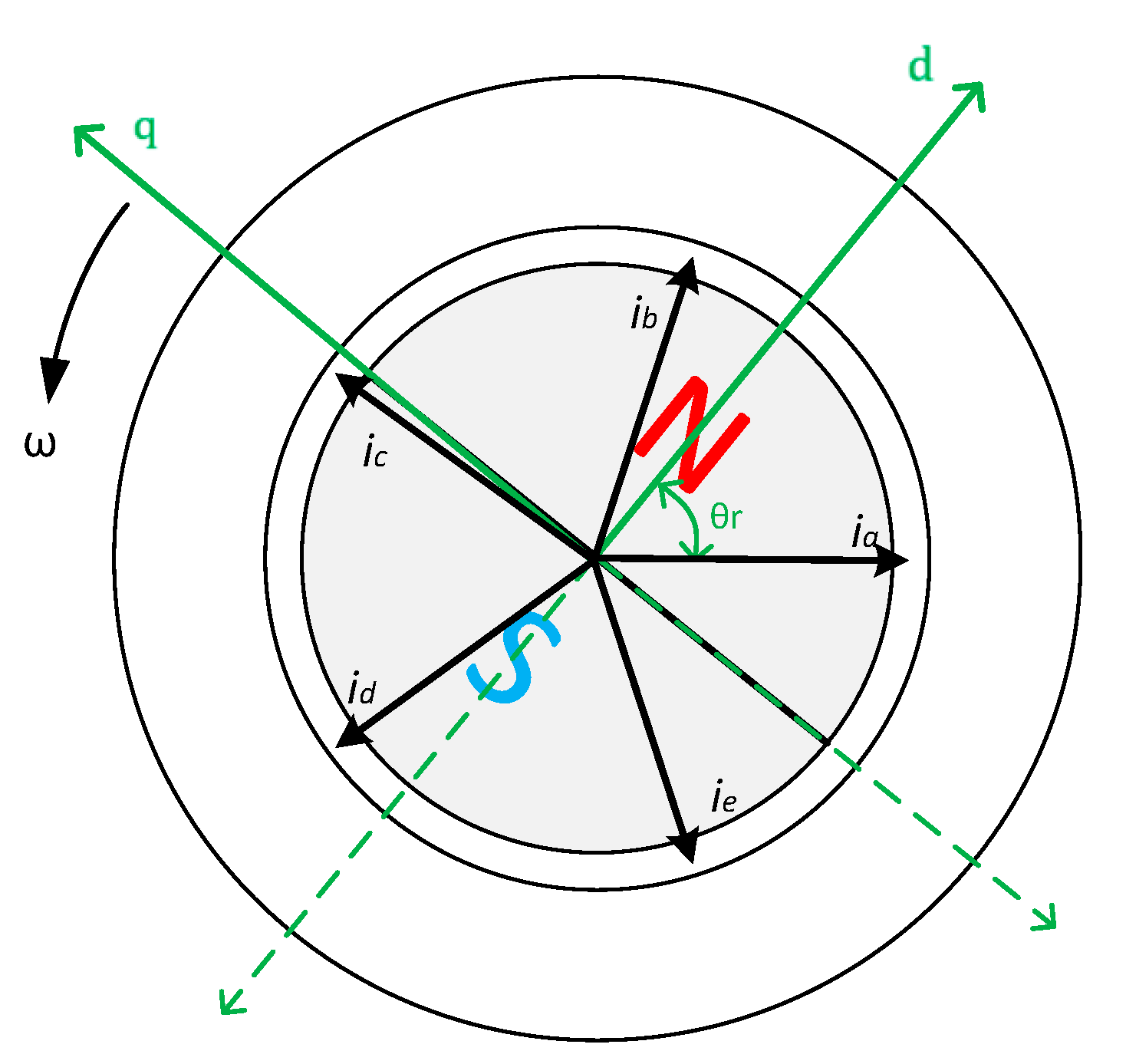
2.1. Direct and Quadrature Axes Currents

Direct and Quadrature (d-q) axes transform of the phase currents involves finding the total projections of the phase currents on the two axes (d-q plane) frame. Generally, the d-q plane is called the rotating frame because it is positioned on the rotor of the machine. The d axis is located in the center of the rotor’s N pole, and q axis is located in the middle of the N and S pole of the rotor. From another point of view, assuming that there are axes in the center of the rotor poles, the q axis will be the bisector of these two axes. For maximum torque production, the projection of total phase currents should be kept in the q axis direction, so the reference current value for the d axis current is set as zero. D-q axes are illustrated in Figure 1 for the two-pole five-phase sinusoidal distributed PM machine.
D-q currents for a sinusoidal distributed winding or sinusoidal back-EMF five-phase machine can be derived from Equation (1). Where θ = ω e t is the electrical angle, ω e is the electrical angular speed, t is the time, and θ r is the rotor position according to the reference phase (Phase A) magnetic flux axis. For this study, the flux axis of phase A has been chosen as a reference. For the concentrated winding or non-sinusoidal back-EMF five-phase machines, these d-q currents in Equation (1) relate to the fundamental current components.
[ I d I q ] = 2 5 [ cos ( θ r ) cos ( θ r 2 π 5 ) cos ( θ r 4 π 5 ) cos ( θ r 6 π 5 ) cos ( θ r 8 π 5 ) s i n ( θ r ) s i n ( θ r 2 π 5 ) s i n ( θ r 4 π 5 ) s i n ( θ r 6 π 5 ) s i n ( θ r 8 π 5 ) ] x [ i a ( θ ) i b ( θ ) i c ( θ ) i d ( θ ) i e ( θ ) ]
Inverse transform of the d-q currents for the sinusoidal distributed winding or sinusoidal back-EMF five-phase machine can be derived from Equation (2).
[ i a ( θ ) i b ( θ ) i c ( θ ) i d ( θ ) i e ( θ ) ] = [ cos ( θ r ) s i n ( θ r ) cos ( θ r 2 π 5 ) s i n ( θ r 2 π 5 ) cos ( θ r 4 π 5 ) s i n ( θ r 4 π 5 ) cos ( θ r 6 π 5 ) s i n ( θ r 6 π 5 ) cos ( θ r 8 π 5 ) s i n ( θ r 8 π 5 ) ] x [ I d I q ]
The balanced five-phase current is given below in Equation (3), Where I m is the amplitude of the phase currents.
i a ( θ ) = I m sin ( θ ) i b ( θ ) = I m sin ( θ 2 π 5 ) i c ( θ ) = I m sin ( θ 4 π 5 ) i d ( θ ) = I m sin ( θ 6 π 5 ) i e ( θ ) = I m sin ( θ 8 π 5 )
I d and I q   currents can be expressed by Equation (4) by applying Equation (3) into Equation (1).
I d = I m sin ( θ r θ ) I q = I m cos ( θ r θ )
According to Equation (4), for maximum torque production, θ r should be equal to θ for a two-pole integral slot five-phase machine. The square root of the sum of the square of I d and I q   in Equation (5) is equal to the amplitude ( I m ) of the phase currents, according to Equation (1).
I d 2 + I q 2 =   I m
The q axis current ( I q   ) should be equal to the amplitude ( I m ) of the phase currents and the d axis current should be zero for maximum torque production. Therefore, the q and d axes currents can be expressed by Equation (6) for maximum torque.
I d = 0 I q = I m

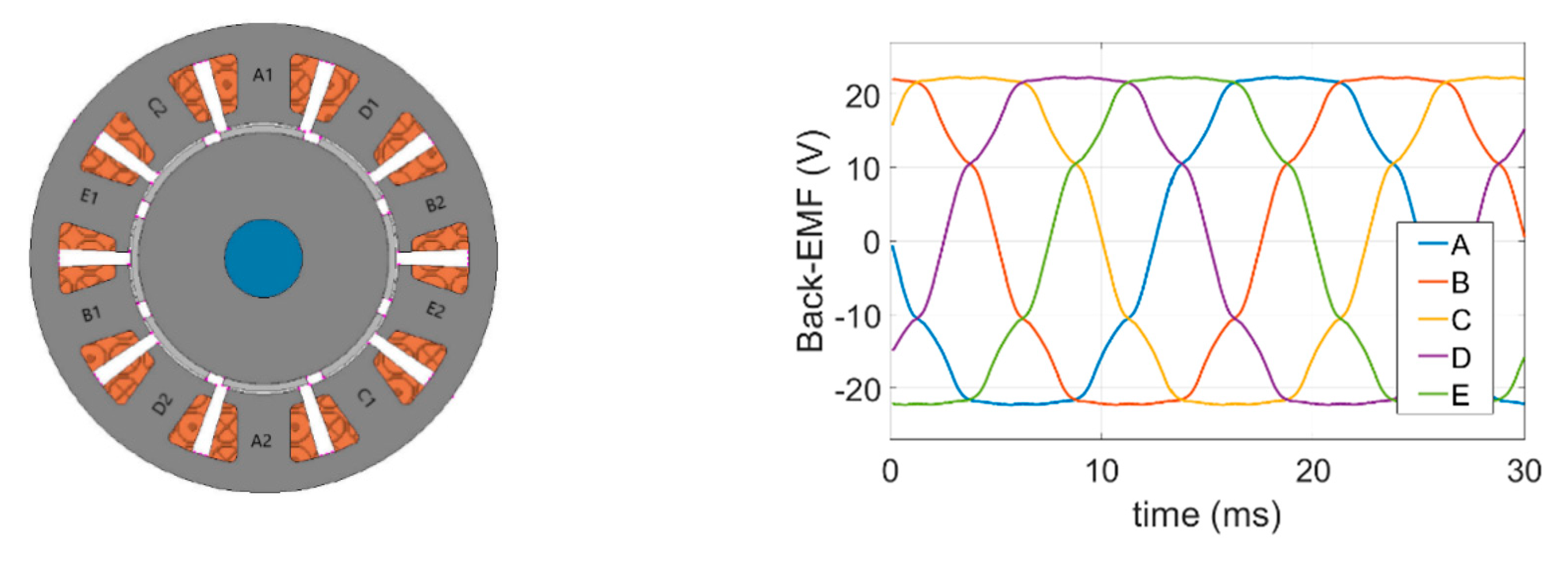
2.2. Resultant (Rotating) Magnetomotive Force of the Sinusoidal Distributed Five-Phase Machine

In a five-phase machine, the phase windings are displaced from each other by 2 π / 5 . In order to produce a resultant (rotating) magnetomotive force (MMF), the balanced five-phase windings should be supplied with balanced five-phase currents, as in Equation (3). The MMF of each phase can be calculated using Equation (7) for the sinusoidally distributed five-phase machine, where N is the number of turns and represents the spatial angle.
f a ( θ , ) = N 2 i a ( θ ) sin ( ) f b ( θ , ) = N 2 i b ( θ ) sin ( 2 π 5 ) f c ( θ , ) = N 2 i c ( θ ) sin ( 4 π 5 ) f d ( θ , ) = N 2 i d ( θ ) sin ( 6 π 5 ) f e ( θ , ) = N 2 i e ( θ ) sin ( 8 π 5 )
The resultant MMF is derived from Equation (8).
f ( θ , ) = f a ( θ , ) + f b ( θ , ) + f c ( θ , ) + f d ( θ , ) + f e ( θ , ) f ( θ , ) = 5 2 [ N 2 I m cos ( θ ) ]
In Equation (8), because the angle, θ , always follows the angle, , the resultant MMF will always be equal to a constant value. Assuming N / 2 = 1 and I m = 1 to ease the calculations, then the resultant MMF is equal to 2.5, as in Equation (9), and this value is going to be used as a reference MMF while obtaining the fault-tolerant control currents using the proposed method.
f ( θ , ) = 2.5

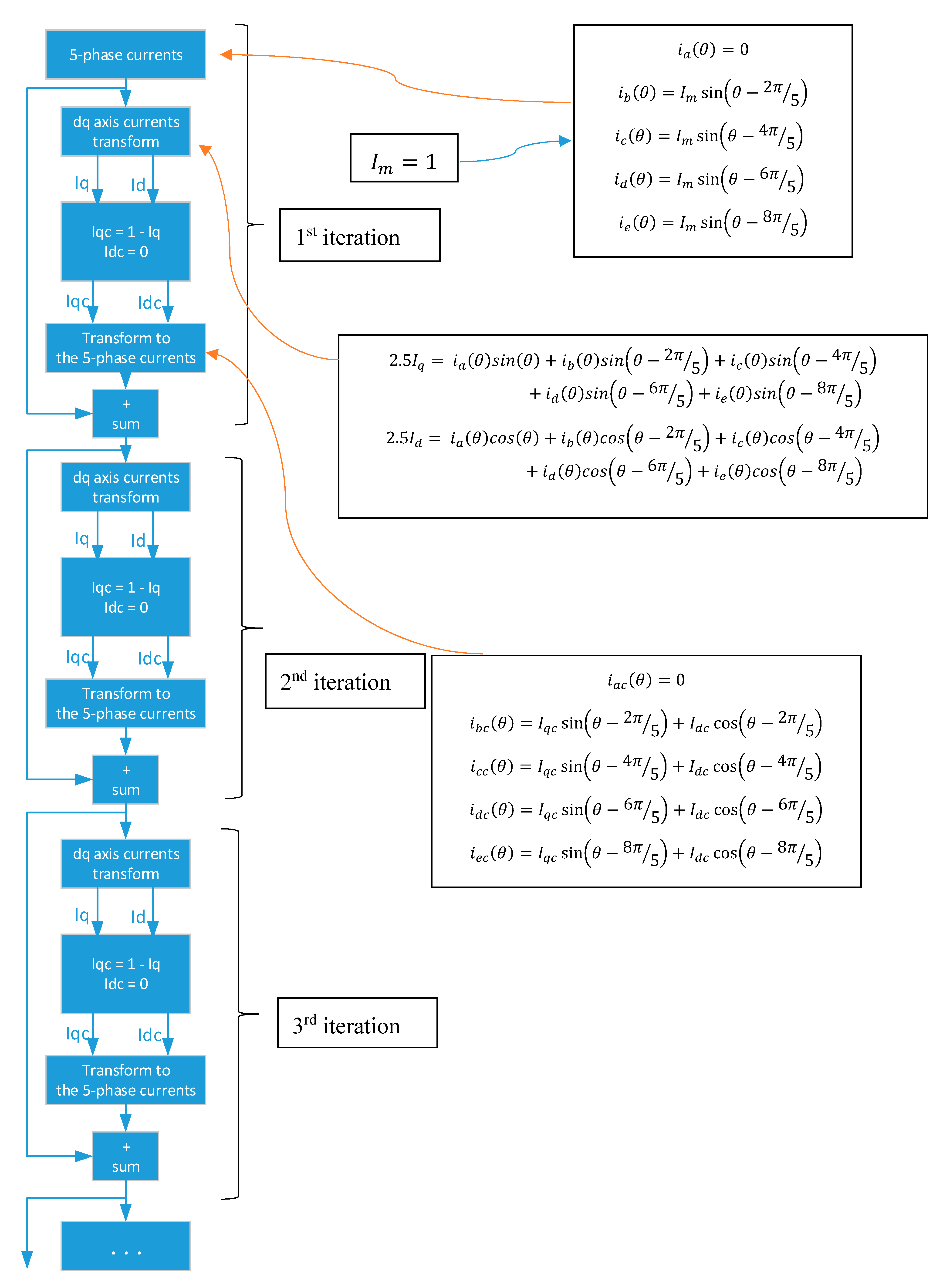
2.3. Open-Circuit Fault-Tolerant Control of a Sinusoidal Distributed Winding Five-Phase Machine

In this study, open-circuit fault-tolerant control currents have been obtained by compensating the d-q currents. Equation (6) is the starting point of this study. For the healthy conditions, I q = I m and I d = 0 for maximum torque. It is assumed that I m = 1 in order to derive the open-circuit fault-tolerant control currents for the remaining healthy phases, so that I q = 1 . When one or more phases are open-circuited, this q axis current I q will no longer be equal to 1. There will be a missing q axis current under the open circuit condition. This missing q axis current ( I q c ) can be obtained using Equation (10).
I d c = 0 I q c = 1 I q
The missing q axis current should be reproduced by using the remaining healthy phases. Additional phase currents are obtained by transforming the missing I d c and I q c currents to the five-phase to compensate the d-q axes currents. Faulty phases (open-circuited ones) should be taken as zero. New currents for the healthy phases are obtained by adding these compensating currents. Then, by transforming these newly obtained resultant phase currents to the d-q axes currents, there will be new compensated I d and I q currents. However, there is still a missing q axis current. These processes are repeated until a smooth rotating magnetomotive force (rotating-MMF) is obtained.
For a clear explanation of the proposed method, a flow diagram can be seen in Figure 2. Assuming phase A is open circuited, Figure 2 shows the flow diagram that can be used to obtain a fault-tolerant control current of the healthy phases under a single-phase open-circuit fault condition. Remaining healthy phase currents are obtained for the phase A open-circuit condition by using the iterative method in Figure 2. Obtaining the new phase currents for the remaining healthy phases under open-circuit fault conditions is explained clearly by the flow diagram in Figure 2.
For all open-circuit fault-conditions, Equation (3) is used as a reference to obtain the fault-tolerant control currents. To ease the calculations, it is assumed that I m = 1 for the open-circuit fault conditions. Amplitude of the currents can be set in the control block of the open-circuit fault-tolerant system according to the d and q axes voltages by using the vector control method.

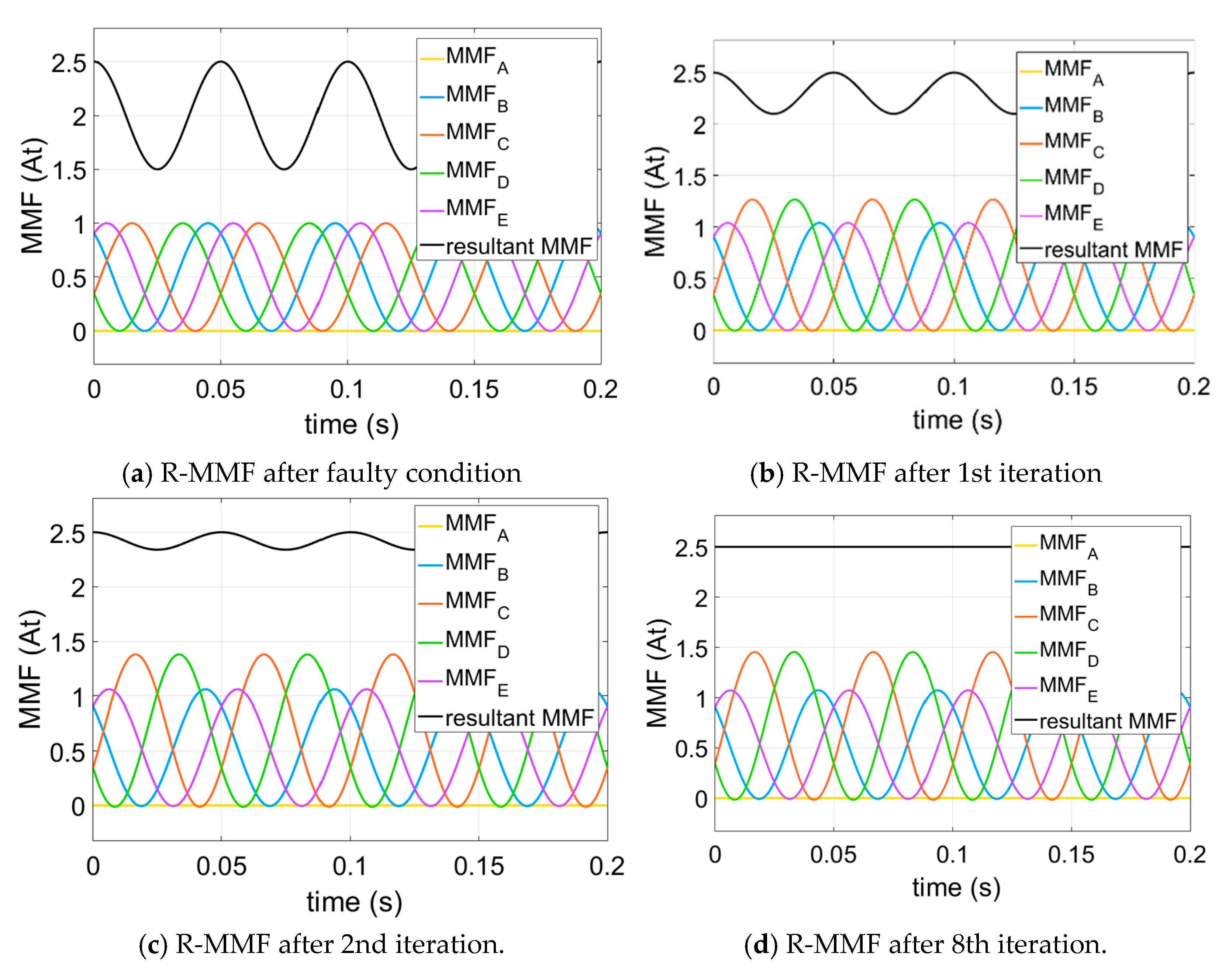
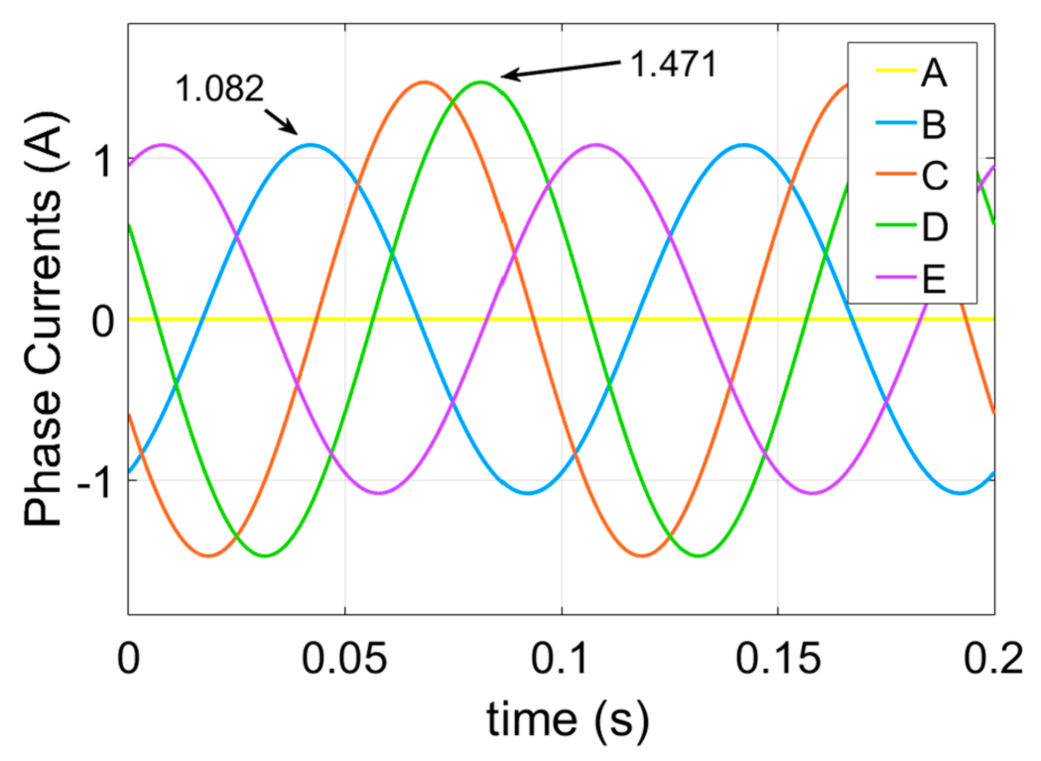
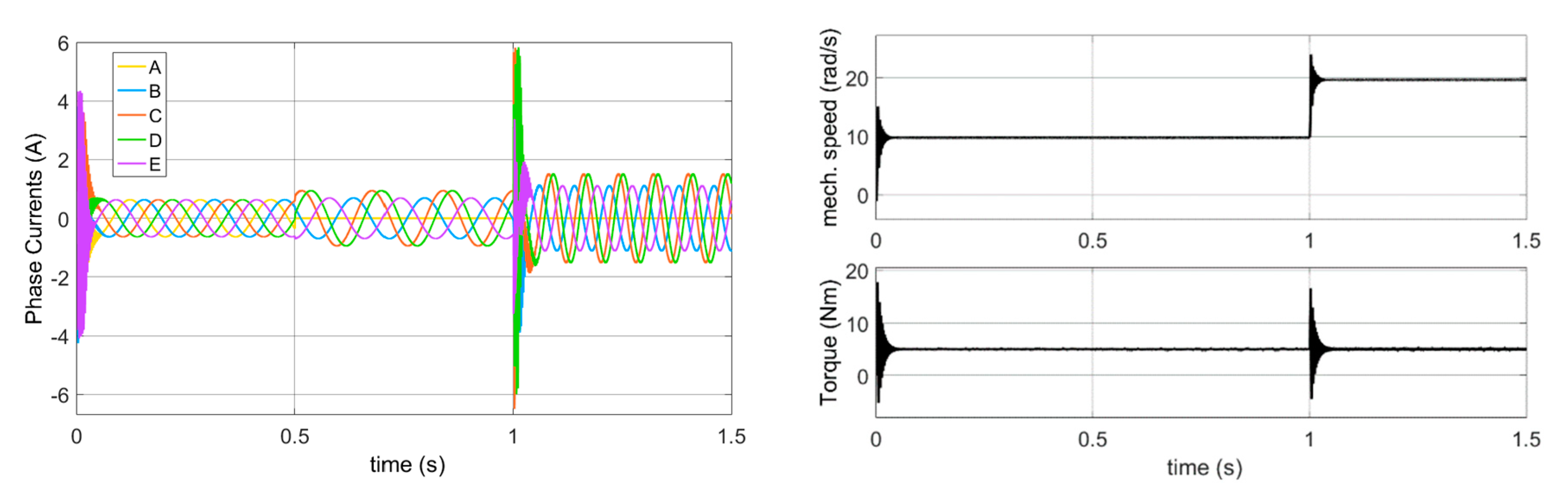
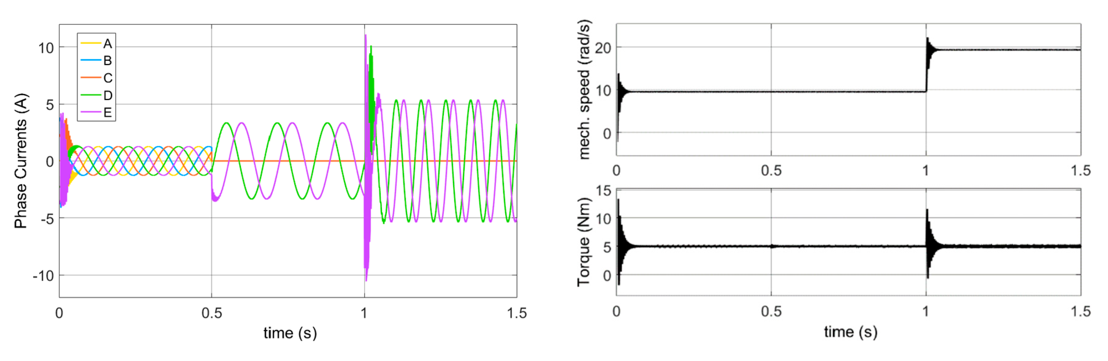
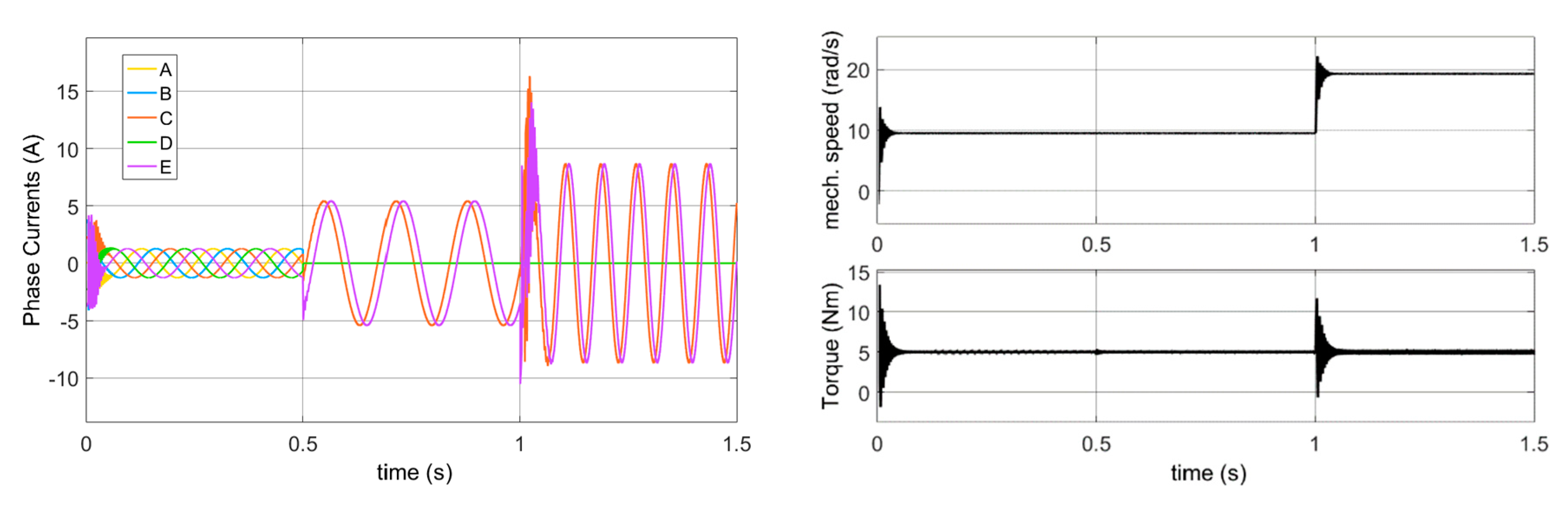
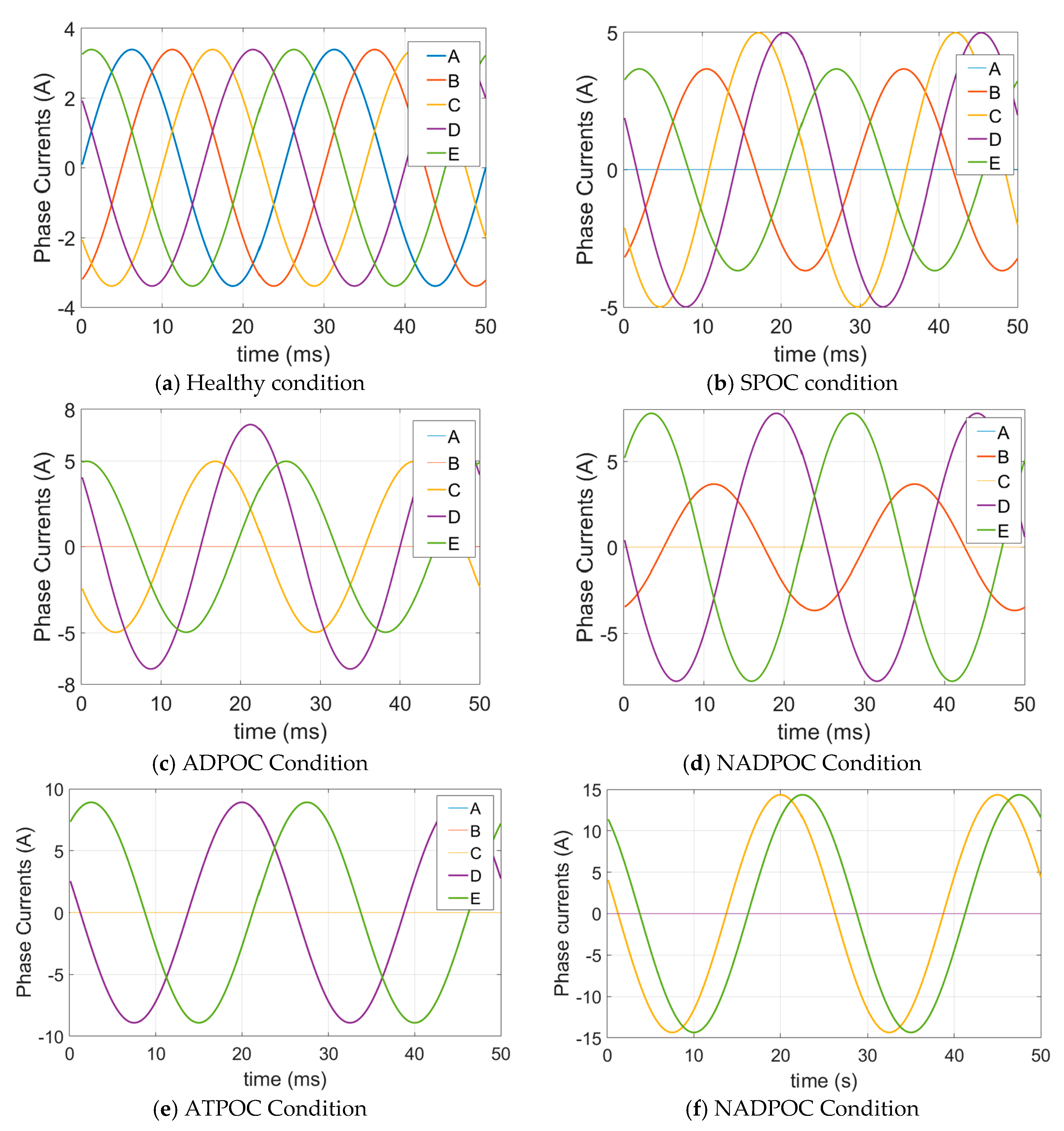
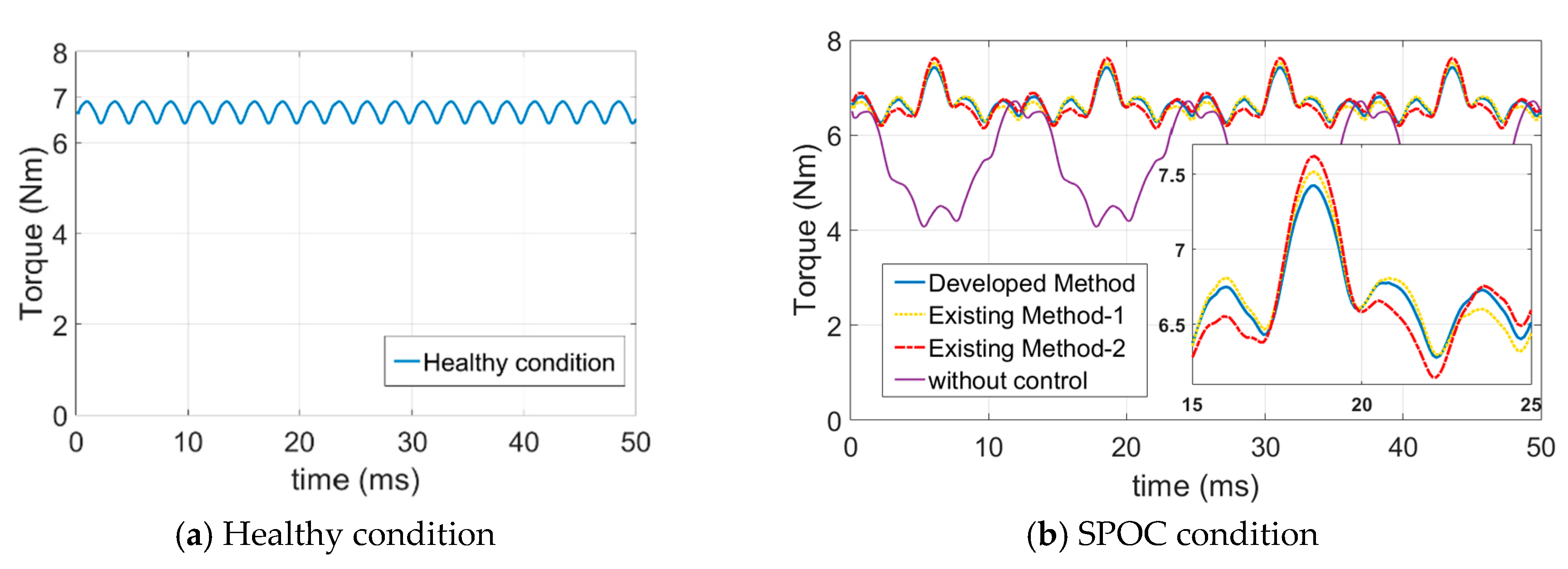
2.3.1. Single-Phase Open-Circuit Condition

Assuming phase A is open circuited for the single-phase open-circuit (SPOC) condition, after the faulty condition, the resultant MMF of the sinusoidally distributed winding five-phase machine can be seen in Figure 3a. It can be seen from Figure 3a that there is a ripple that changes between 1.5 At and 2.5 At in the resultant MMF. The reflection of this ripple in the rotating MMF will be in the torque. Applying the proposed method to obtain the remaining healthy phase currents, resultant MMFs are shown in Figure 3b–d after the 1st, 2nd, and 8th iteration, respectively. It is clear from Figure 3b–d that ripple in the resultant MMF disappears slowly as the number of iterations increases. In Figure 3d, which shows the resultant MMF after the 8th iteration, the resultant MMF is flat and has no ripple. Its value is 2.5 At, as in the healthy condition of the sinusoidally distributed five-phase machine, which means the obtained currents after the 8th iteration can be used for the SPOC fault-tolerant condition when phase A is open circuited. The remaining healthy phase currents are illustrated in Figure 4. The coefficient of the remaining healthy phase currents can be seen in Figure 4 as well.

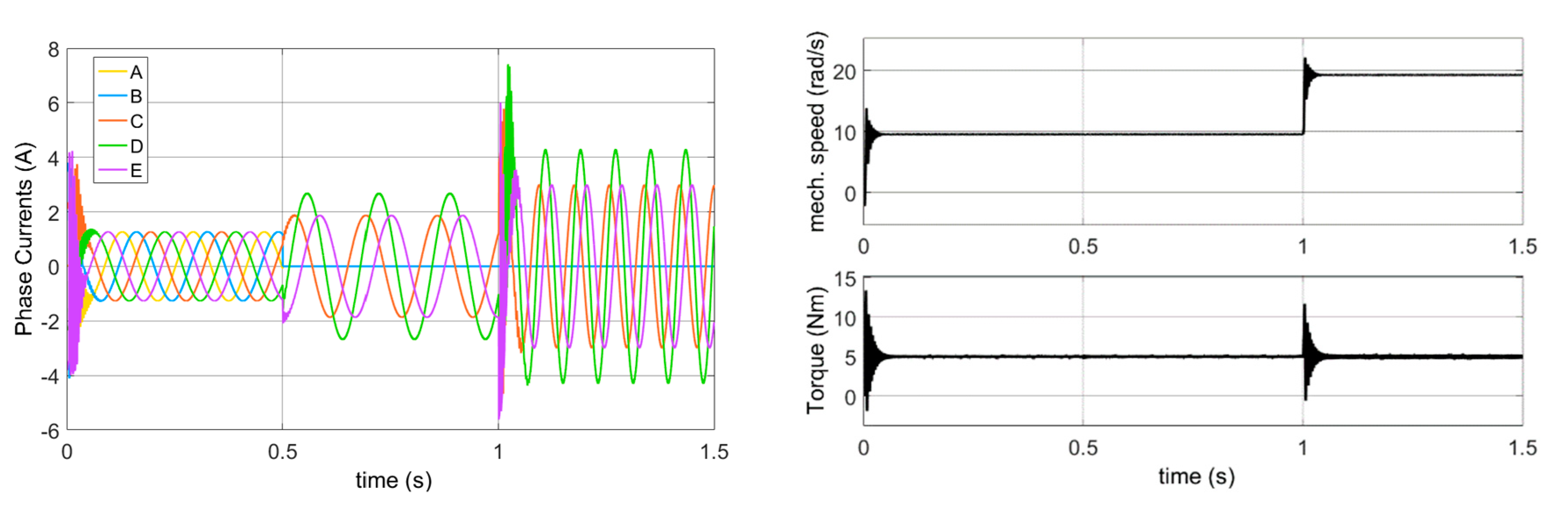
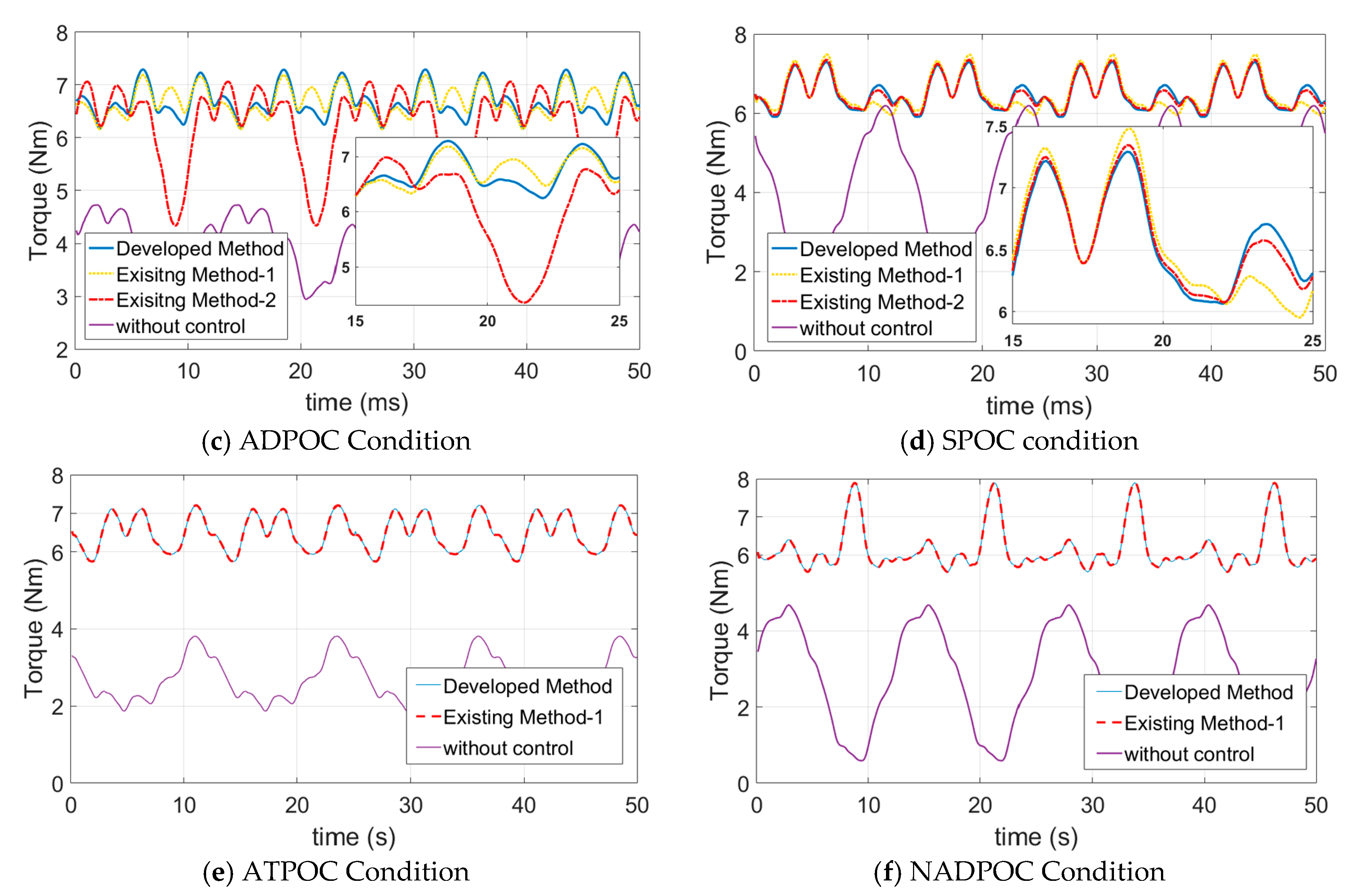
2.3.2. Adjacent Double-Phase Open-Circuit Condition

Phase A and Phase B are assumed to be open circuited for the adjacent double-phase open-circuit (ADPOC) condition. After the ADPOC fault condition, the resultant MMF of the ADPOC condition is shown in Figure 5a. It has a ripple and changes between 1 At and 2 At. After applying the proposed method for the ADPOC condition, the resultant MMF increases and then settles at a level of 2.5 At. The ripple in the resultant MMF decreases as the resultant MMF increases, and it finally disappears at the level of 2.5 At. Twelve iterations have been done to get a smooth rotating MMF. The resultant MMFs after the 1st, 2nd, and 12th iteration can be seen in Figure 5b–d. The resultant currents that have been obtained after the 12th iteration can be used for the ADPOC fault-tolerant control. The obtained phase currents for the remaining healthy phases are shown in Figure 6.

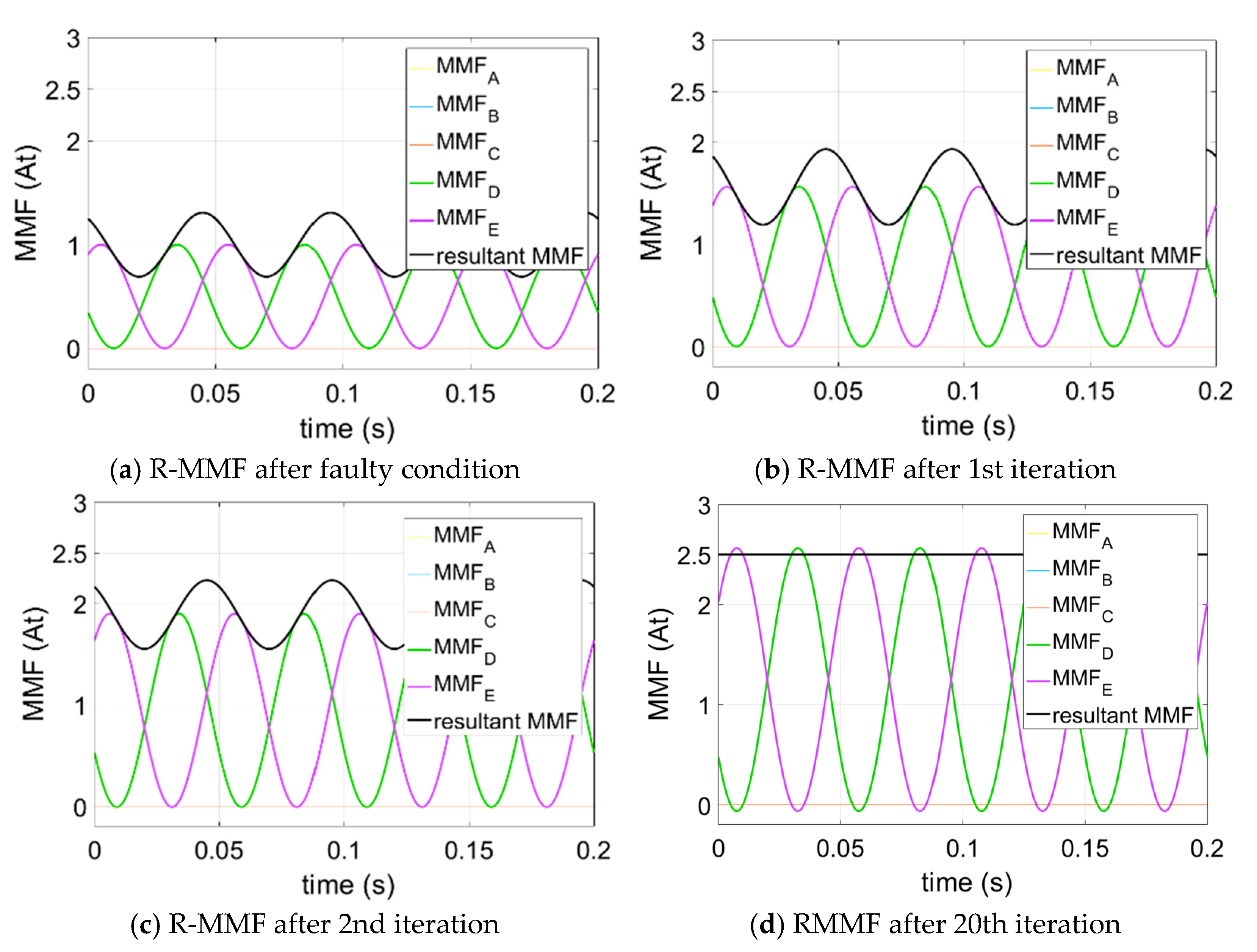
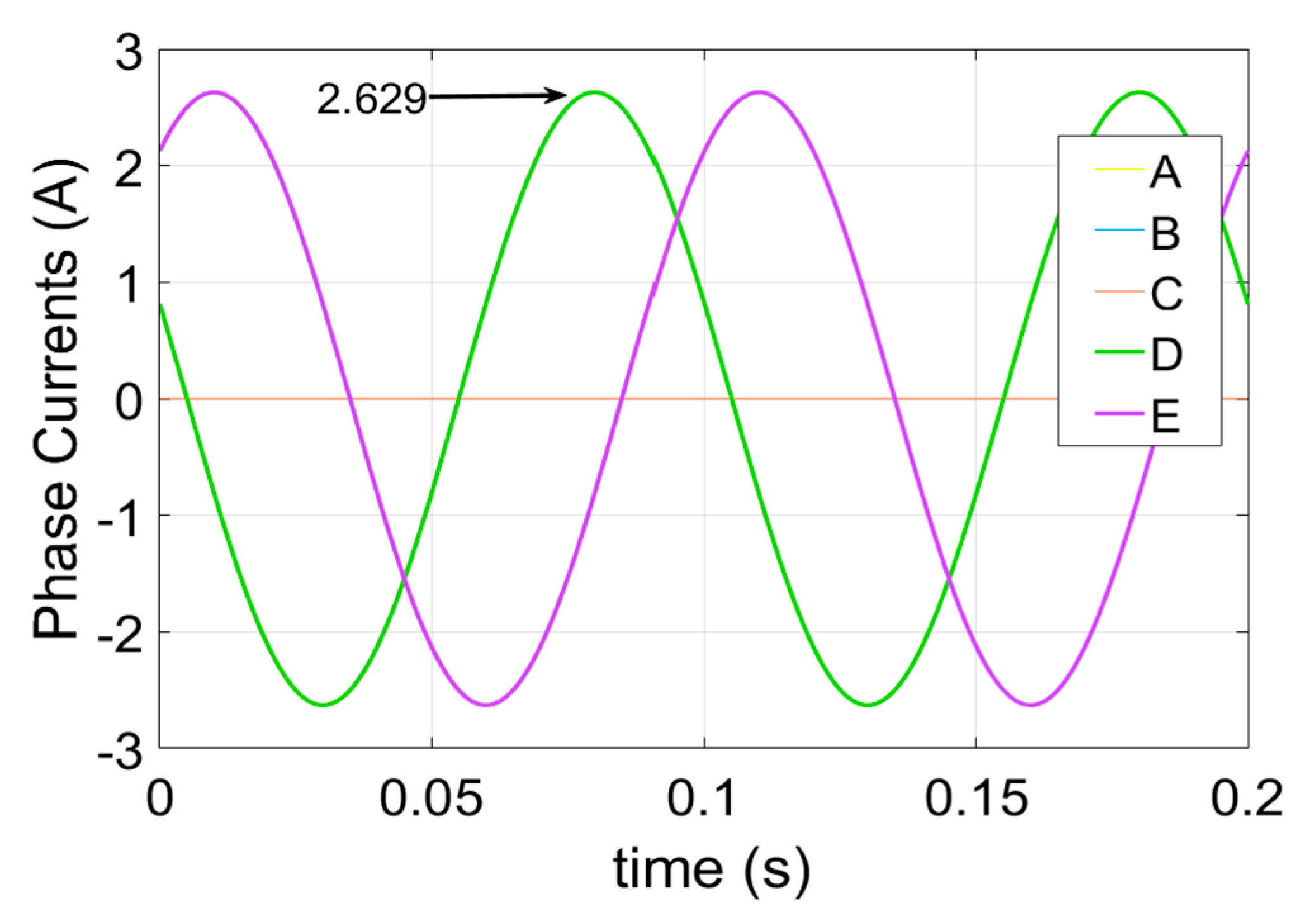
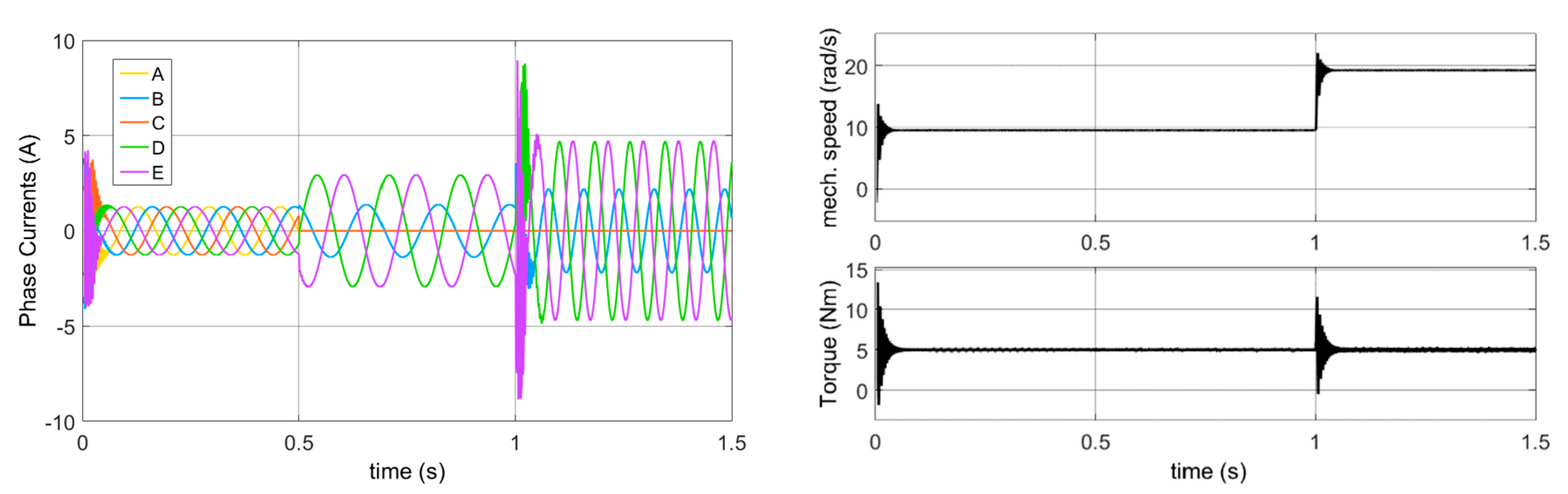
2.3.3. Non-Adjacent Double-Phase Open-Circuit Condition

For this condition, it is assumed that phase A and phase C are open circuited. After the faulty condition, the resultant MMF can be seen in Figure 7a. The resultant MMF has a ripple as in the previous open-circuit fault conditions. After applying the proposed method, the amplitude of the ripple is reduced a little after the 1st iteration. The ripple in the resultant MMF decreases as the number of iterations increases, as in the previous conditions. The resultant MMF is a flat line at the level of 2.5 At after the 18th iteration. The resultant MMFs belonging to the 1st, 2nd, and 18th iterations can be seen in Figure 7b–d, respectively. The resultant currents are obtained after the 18th iteration, and the waveform of these currents can be seen in Figure 8.

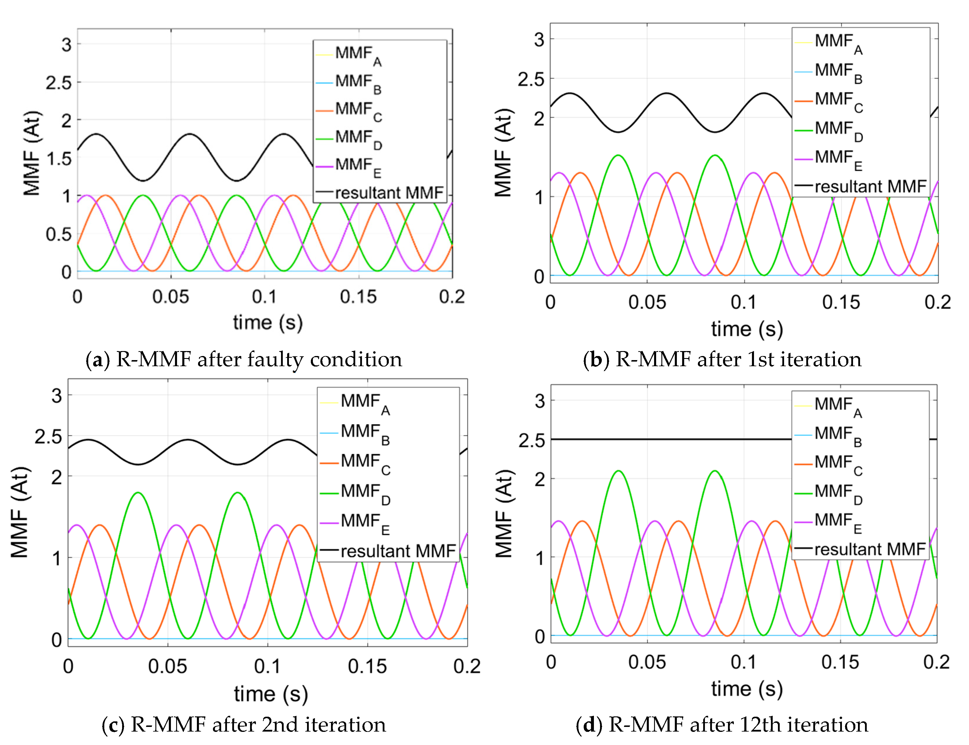
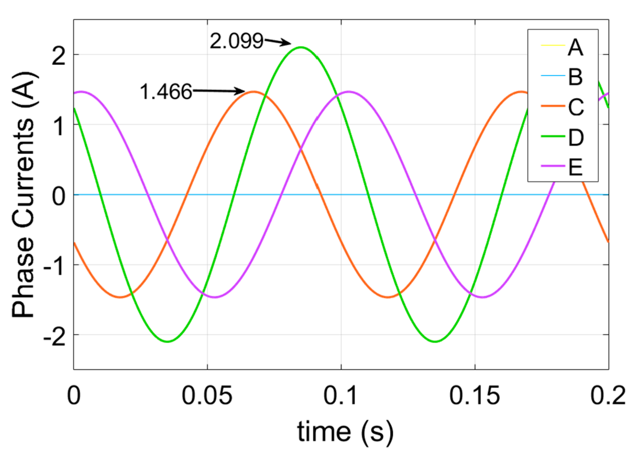
2.3.4. Adjacent Three-Phase Open Circuit Condition

Assuming that phase A, phase B, and phase C are open circuited for the adjacent three-phase open-circuit (ATPOC) condition, the resultant MMFs for the after faulty condition and the 1st, 2nd, and 20th iteration can be seen in Figure 9a–d. The resultant MMF reaches and settles down after the 20th iteration at 2.5 At. The required currents for the ATPOC fault-tolerant control is shown in Figure 10.

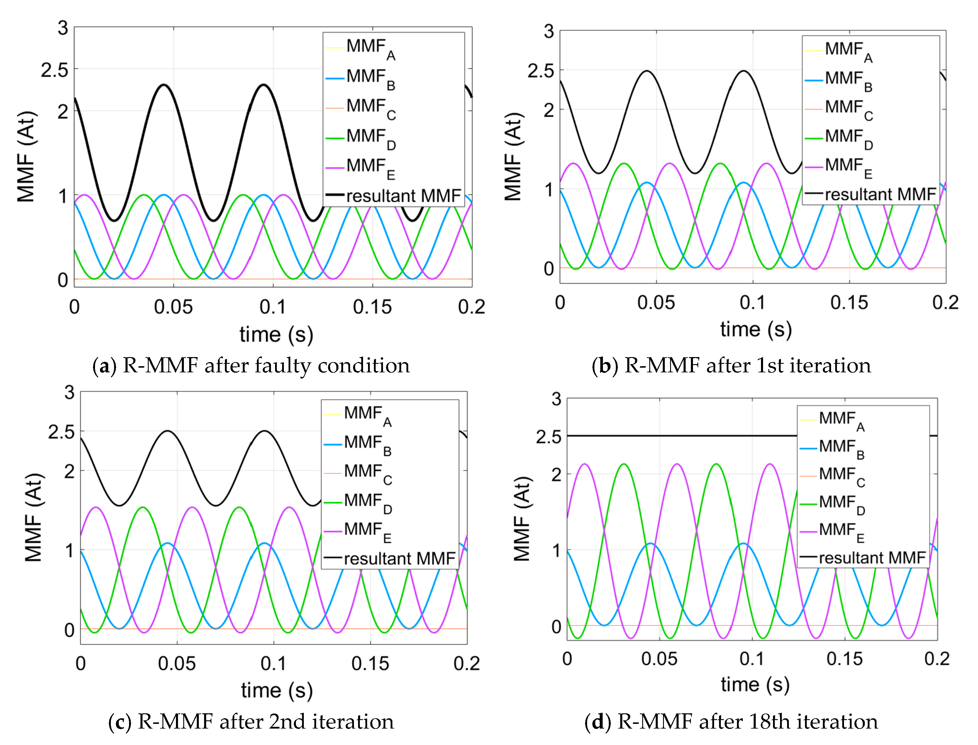
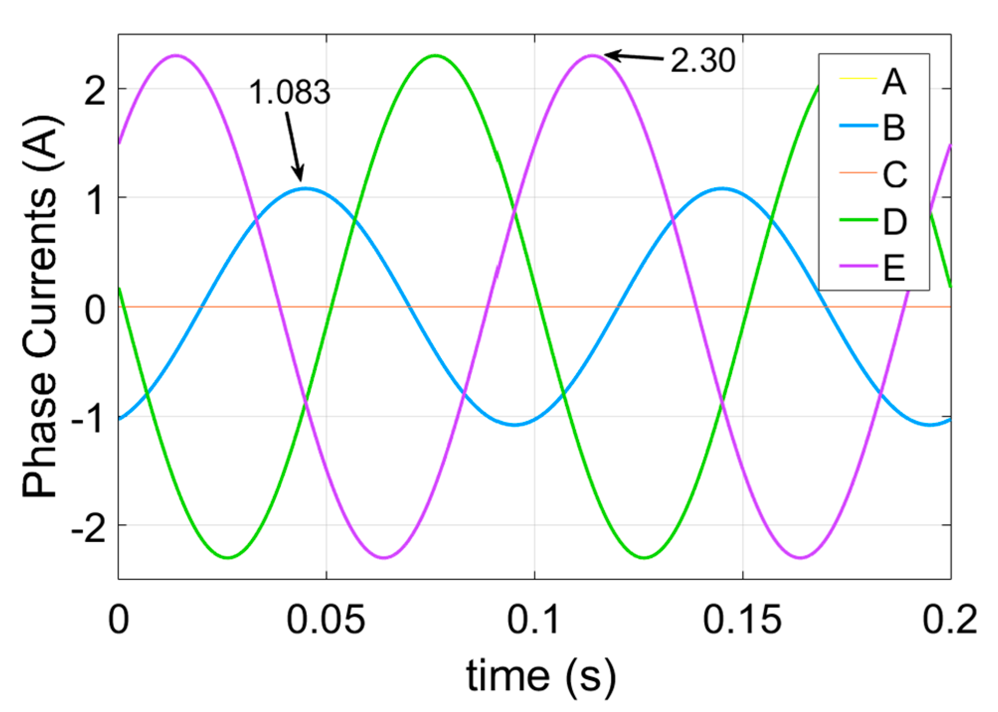
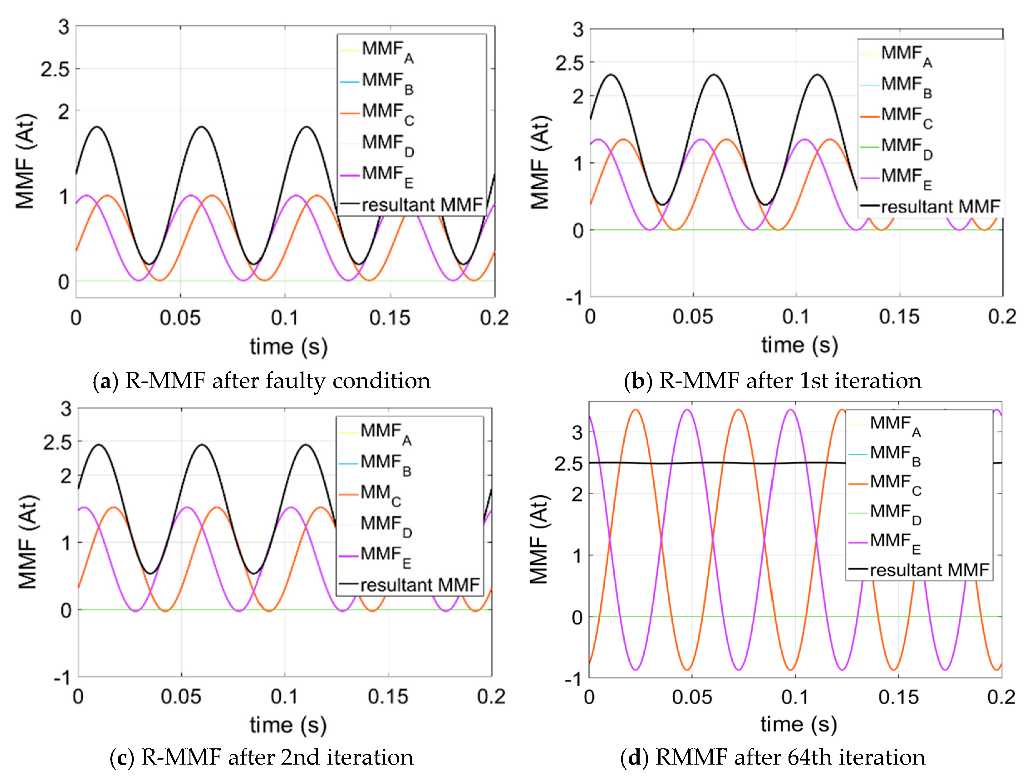
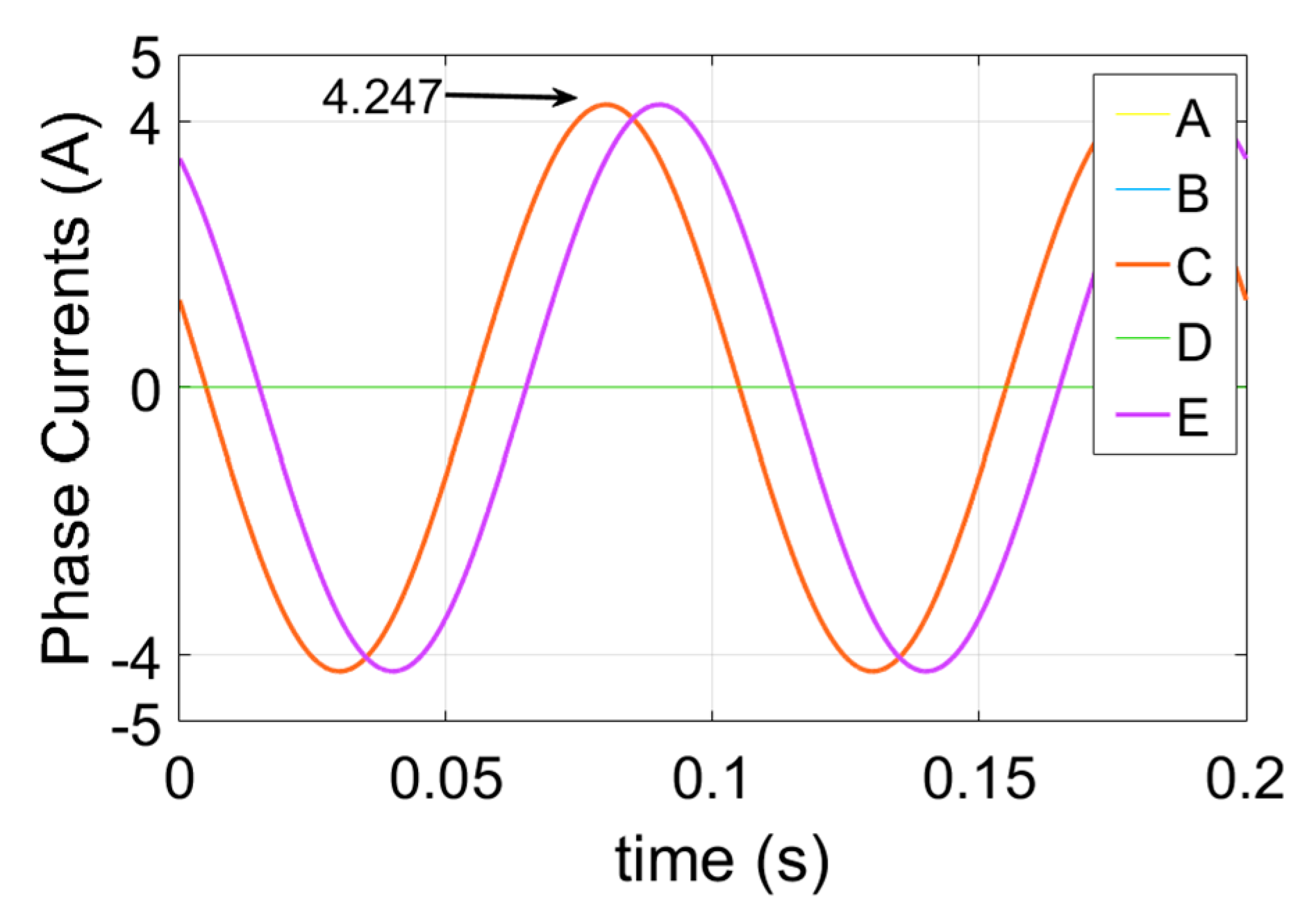
2.3.5. Non-Adjacent Three-Phase Open Circuit Condition

It is assumed that phase A, phase B, and phase D are open circuited for the non-adjacent three-phase open-circuit (NATPOC) condition. The resultant MMFs after the NATPOC condition and the 1st, 2nd, and the 64th iteration can be seen in Figure 11a–d, respectively. The number of iterations for the smooth resultant MMF is 64, which is very high compared to the previous open-circuit fault conditions. The resultant currents for the ATPOC fault-tolerant control are shown in Figure 12.

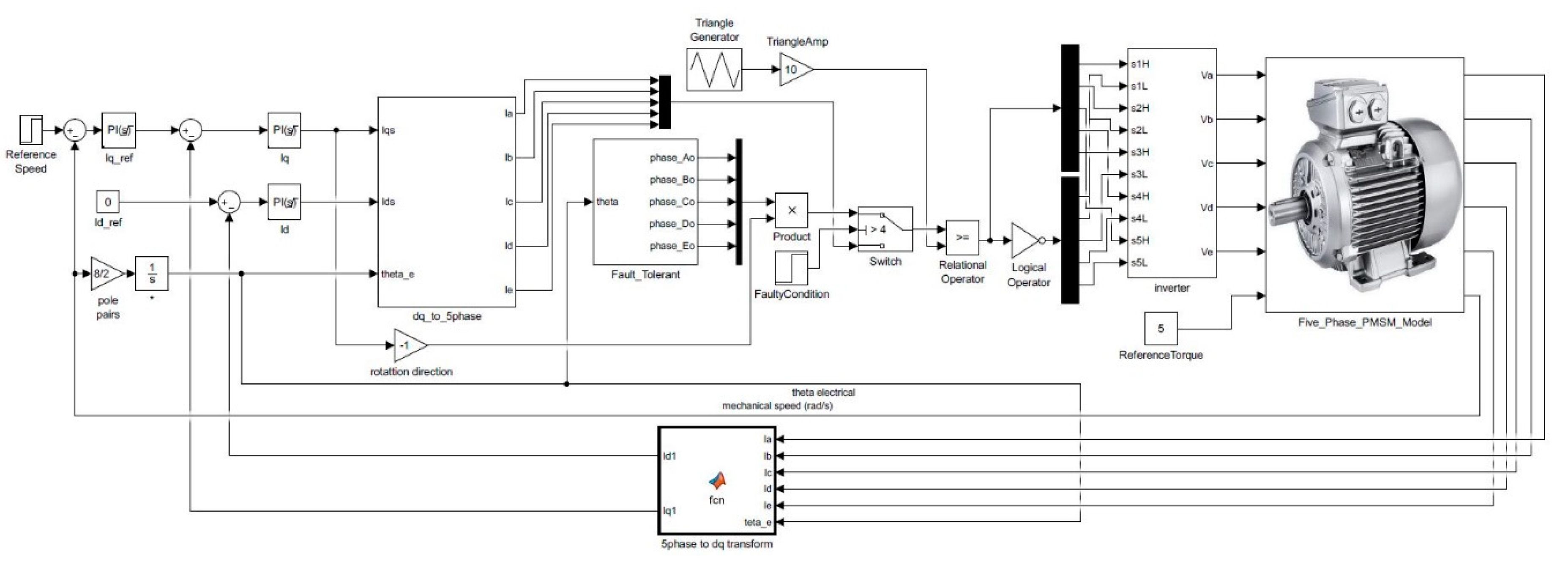
3. MATLAB/Simulink Simulation of the Proposed Method

In this section, MATLAB/Simulink simulation results have been presented. For the simulations, a d-q modelled five-phase sinusoidal PM machine has been used. The parameters belonging to the modelled five-phase permanent magnet synchronous machine (PMSM) can be seen in Table 1.
A control block has been developed to simulate the open-circuit fault-tolerant elements of the five-phase machine on the MATLAB/Simulink software. The block diagram of the control system can be seen in Figure 13. A vector control method has been used to control the machine. The obtained open-circuit fault-tolerant control currents have been stored in a lookup table. The required theta information comes from the machine to produce the remaining healthy phases. The amplitude of the phase currents for both healthy and open-circuit fault conditions is determined according the mechanical speed of the machine by using a PI controller.
Simulations have been done for the five open-circuit fault-tolerant controls. These are SPOC, ADPOC, NADPOC, ATPOC, and NATPOC conditions. The duration of the simulations is 1.5 s. The starting mechanical speed is 10 rad/s and the reference torque is 5 Nm. It is assumed that, for the five different fault-tolerant conditions, the open-circuit fault condition has occurred at 0.5 s and speed has been increased to 20 rad/s at 1 s. The phase voltages, mechanical speed, and the torque output of the machine can be seen in Figure 14, Figure 15, Figure 16, Figure 17 and Figure 18 for all the five different open-circuit fault conditions. The simulation of the proposed open-circuit fault-tolerant control currents has been performed successfully, as seen in Figure 14, Figure 15, Figure 16, Figure 17 and Figure 18 for the PMSM machine.

4. Simulation on an FEA Model

The simulation using MagNet, a finite element electromagnetic (EM) modelling software package with a motion solver for five-phase machines, has been undertaken to examine the torque of the five-phase PMSM for the five different open-circuit fault-tolerant control currents. The output torques have been obtained from a two-dimensional (2D) FEA model.
The rated current of the five-phase machine model has been used as the reference current for healthy and open-circuit fault-tolerant conditions, and the other parameters that belongs to the machine are presented in Table 2. The FEA model and the back-EMF waveform of the five-phase PM machine can be seen in Figure 19.
The simulated model five-phase machine shown in Figure 19 is a fractional slot concentrated winding machine with 10 slots and 8 poles. The back-EMF waveform of the FEA model of the five-phase machine can also be seen in Figure 19. The harmonic content of back-EMF includes 100% fundamental, the 3rd harmonic: 9.6%, the 5th: 0%, the 7th: 3.23%, the 9th: 3.01%, and the 11th: 0.52%. Because the developed theory is for a sinusoidal back-EMF or sinusoidally distributed winding five-phase machine, the ripple in the torque is inevitable under the fault-tolerant conditions.
The current waveforms of the healthy and the five open-circuit fault-tolerant conditions are shown in Figure 20. These current waveforms are input into the ports of the healthy windings under healthy and open-circuit fault-tolerant conditions. The torque results for the healthy condition can be seen in Figure 21a. The average torque of the healthy condition is 6.6966 Nm, and the torque has ripple due to cogging torque and higher order back-EMF harmonics. In particular, the 9th and 11th harmonics cause this small ripple under the healthy condition because supplied sinusoidal five-phase balanced currents interact with the fundamental, the 9th, and the 11th harmonic components of the back-EMF. The interaction between the five-phase balanced currents and the fundamental component of the back-EMF produces smooth torque. However, the interaction between balanced five-phase currents and the 9th and the 11th harmonic will cause ripple in the torque.
In this study, the aim was that the same torque found in the healthy condition is obtained under open circuit fault-tolerant conditions for the FEA simulations. The torque waveform that is obtained using the developed method is compared with torque waveforms that belong to two existing methods, as seen in Figure 21. One of the existing methods (Existing method-1) was developed in [8,14]. In this method, the authors tried to control the machine without changing the hardware. However, this method limits the number of open-circuit fault conditions. The other method (Existing method-2) for the open-circuit fault-tolerant condition was developed in [12]. In this method, the authors kept the phase current amplitude equal to each other under open-circuit fault-tolerant conditions. For this method, a neutral connection is required, as in the developed method in this study. Because of the neutral connection, the five-phase machine can operate smoothly up to the three-phase open-circuit fault condition. It is useful to stress that the developed method, existing method-1, and existing method-2 were developed for the sinusoidal back-EMF or sinusoidal distributed winding PM machines. Therefore, using these methods for the non-sinusoidal back-EMF machines causes ripple in the torque.
The torque results of the five different open-circuit fault-tolerant conditions with the existing methods are shown in Figure 21b–f. As can be seen in Figure 21, approximately the same torque waveform and the same average torque has been obtained for the SPOC and ADPOC fault-tolerant control conditions, with only a small ripple. A similar torque has been obtained under the developed method when compared to the existing methods. The torque ripple for the NADPOC, ATPOC, and NATPOC conditions are a bit higher than for the SPOC and ADPOC fault-tolerant conditions for all methods. This ripple, which is caused by higher order back-EMF harmonics, can be ignored compared to the ripple without control conditions. Under the healthy conditions, there are no interactions between certain harmonics (3rd, 5th, 7th, 13th, etc.). However, the open-circuit fault-tolerant control currents interact with certain harmonics (3rd, 5th, 7th, 9th, etc.) under fault-tolerant conditions. The new obtained currents for the fault-tolerant conditions will have new amplitude and phase angles. Because of these changes, there will be unwanted interactions between the new obtained phase currents and the higher order harmonics (3rd, 5th, 7th, 9th, etc.) of back-EMF for the fault tolerant control. These interactions cause ripples in the torque. As the amplitude of the back-EMF harmonics increases, percentage (amplitude) of the ripple in the torque also increases. In particular, the third harmonic of back-EMF of the five-phase machine produces higher ripples for these FEA simulations for the fault-tolerant control due to having higher amplitude compared to the other higher order back-EMF harmonics.
A comparison has been made between the developed method and the existing methods in Table 3 according to their total ohmic losses. The developed method has better ohmic loss performance compared to the existing methods.

5. Conclusions

In this paper, a new method has been developed to run machines under open-circuit fault conditions. Fault-tolerant control currents have been obtained for the five-different open-circuit fault conditions. These are SPOC, ADPOC, NADPOC, TPOC, and NTPOC fault conditions.
The d-q axes currents have been compensated to obtain the open-circuit fault-tolerant control currents by using an iterative method. For this purpose, the d-q axis currents that are in the healthy condition have been used as reference currents by assuming these currents are positioned for the maximum torque. Iterations to obtain the remaining healthy phase currents for the faulty conditions have been repeated until a smooth rotating MMF for a sinusoidal distributed winding five-phase machine is obtained. The number of iterations increases as the number of faulty phases increases. Additionally, the number of iterations increases when the faulty condition moves from the adjacent to the non-adjacent faulty phases. As a result, fault-tolerant control currents have been obtained for the five-different open-circuit fault conditions.
In Section 3, the obtained fault-tolerant currents for the faulty conditions have been simulated in MATLAB/Simulink. The developed method has been tested by using a d-q model of five-phase PMSM. For this purpose, a vector control block diagram has been built to simulate the fault-tolerant control currents. The d-q model of the five-phase machine has been run successfully under five open-circuit fault conditions by using the obtained fault-tolerant currents. In Section 4, the FEA simulation of a fractional slot five-phase machine has been undertaken to test the obtained open-circuit fault-tolerant currents for the five conditions. According to the FEA simulation results, satisfactory torques are obtained for all five open-circuit fault conditions, apart from a small ripple due to higher order (3rd, 5th, 7th, 9th, etc.) back-EMF harmonics.
As a result, this developed method for open-circuit fault conditions is for a sinusoidal winding distributed or sinusoidal back-EMF five-phase machine. This developed method can be applied to any sinusoidally distributed winding or sinusoidal back-EMF multi-phase and three-phase machine. A method can be developed for concentrated or non-sinusoidal back-EMF multi-phase machines.

Author Contributions

Conceptualization, A.A.; methodology, A.A.; software, A.A. and P.L.; validation, A.A. and P.L.; formal analysis, A.A.; investigation, A.A.; writing—original draft preparation, A.A.; writing—review and editing, A.A. and P.L.; visualization, A.A.; supervision, P.L.; project administration, P.L.; funding acquisition, A.A. and P.L. All authors have read and agreed to the published version of the manuscript.

Funding

This research received no external funding.

Institutional Review Board Statement

Not applicable.

Informed Consent Statement

Not applicable.

Data Availability Statement

Data is contained within the article.

Conflicts of Interest

The authors declare no conflict of interest.

References

  1. Levi, E. Multiphase Electric Machines for Variable-Speed Applications. IEEE Trans. Ind. Electron. 2008, 55, 1893–1909. [Google Scholar] [CrossRef]
  2. Scuiller, F. Magnet Shape Optimization to Reduce Pulsating Torque for a Five-Phase Permanent-Magnet Low-Speed Machine. IEEE Trans. Magn. 2013, 50, 1–9. [Google Scholar] [CrossRef] [Green Version]
  3. Barrero, F.; Duran, M.J. Recent Advances in the Design, Modeling, and Control of Multiphase Machines—Part I. IEEE Trans. Ind. Electron. 2016, 63, 449–458. [Google Scholar] [CrossRef]
  4. Lipo, T.A.; Toliyat, H.A.; White, J.C. A Concentrated Winding Induction Machine. Energy 1991, 6, 1–5. [Google Scholar]
  5. Levi, E.; Barrero, F.; Duran, M.J. Multiphase machines and drives—Revisited. IEEE Trans. Ind. Electron. 2016, 63, 429–432. [Google Scholar] [CrossRef] [Green Version]
  6. Toliyat, H.; Waikar, S.; Lipo, T. Analysis and simulation of five-phase synchronous reluctance machines including third harmonic of airgap MMF. IEEE Trans. Ind. Appl. 1998, 34, 332–339. [Google Scholar] [CrossRef] [Green Version]
  7. Parsa, L. Performance Improvement of Permanent Magnet Ac Motors. J. Biol. Chem. 2005, 280, 33960–33967. [Google Scholar]
  8. Ding, S.; Chen, W.; Tong, M.; Xie, F.; Zheng, C. Fault tolerant control for a five-phase permanent magnet synchronous machine driving system. In Proceedings of the 2016 IEEE 11th Conference on Industrial Electronics and Applications (ICIEA), Hefei, China, 5–7 June 2016; pp. 2021–2025. [Google Scholar] [CrossRef]
  9. Shin, H.; Baek, S.K.; Lee, K. Five-Phase Induction Motor Driving System. In Proceedings of the 2016 IEEE 8th International Power Electronics and Motion Control Conference (IPEMC-ECCE Asia), Hefei, China, 22–26 May 2016; pp. 2487–2492. [Google Scholar]
  10. Jack, A.G.; Mecrow, B.C.; Haylock, J. A Comparative Study of Permanent Magnet and Switched Reluctance Motors for High Performance Fault Tolerant Applications. IEEE Trans. Ind. Appl. 1995, 32, 734–740. [Google Scholar]
  11. Lipo, T.A. A strategy for improving reliability of field oriented controlled induction motor drives. In Proceedings of the IEEE Idustry Applications Society Annual Meeting, Dearborn, MI, USA, 28 September–4 October 1991. [Google Scholar]
  12. Sui, Y.; Zheng, P.; Yin, Z.; Wang, M.; Wang, C. Open-Circuit Fault-Tolerant Control of Five-Phase PM Machine Based on Reconfiguring Maximum Round Magnetomotive Force. IEEE Trans. Ind. Electron. 2019, 66, 48–59. [Google Scholar] [CrossRef]
  13. Fu, J.; Lipo, T.A. Disturbance-Free Operation of a Multiphase Current-Regulated Motor Drive with an Opened Phase. IEEE Trans. Ind. Appl. 1994, 30, 5–12. [Google Scholar]
  14. Parsa, L.; Toliyat, H.A. Fault-Tolerant Five-Phase Permanent Magnet Motor Drives. In Proceedings of the Conference Record of the 2004 39th IEEE Industry Applications Conference, Seattle, WA, USA, 3–7 October 2004; Volume 2, pp. 1048–1054. [Google Scholar]
  15. Dwari, S.; Parsa, L. Open-circuit Fault Tolerant Control of Five-Phase Permanent Magnet Motors with Third-Harmonic Back-EMF. In Proceedings of the 34th Annual Conference of IEEE Industrial Electronics, Orlando, FL, USA, 10–13 November 2008. [Google Scholar]
  16. Dwari, S.; Parsa, L. Fault-Tolerant Control of Five-Phase Permanent-Magnet Motors With Trapezoidal Back EMF. IEEE Trans. Ind. Electron. 2011, 58, 476–485. [Google Scholar] [CrossRef]
  17. Mohammadpour, A.; Sadeghi, S.; Parsa, L. Fault-tolerant control of five-phase PM machines with pentagon connection of stator windings under open-circuit faults. In Proceedings of the 2012 Twenty-Seventh Annual IEEE Applied Power Electronics Conference and Exposition (APEC), Orlando, FL, USA, 5–9 February 2012; pp. 1667–1672. [Google Scholar]
  18. Mohammadpour, A.; Gandhi, A.; Parsa, L. Design and control of fault-tolerant permanent magnet machines. In Proceedings of the 2013 IEEE Workshop on Electrical Machines Design, Control and Diagnosis (WEMDCD), Paris, France, 11–12 March 2013; Volume 12180, pp. 108–116. [Google Scholar]
  19. Mohammadpour, A.; Parsa, L. Post-fault control technique for multi-phase PM motor drives under short-circuit faults. In Proceedings of the 2013 Twenty-Eighth Annual IEEE Applied Power Electronics Conference and Exposition (APEC), Long Beach, CA, USA, 17–21 March 2013; pp. 817–822. [Google Scholar]
  20. Mohammadpour, A.; Mishra, S.; Parsa, L. Fault-Tolerant Operation of Multiphase Permanent-Magnet Machines Using Iterative Learning Control. IEEE J. Emerg. Sel. Top. Power Electron. 2014, 2, 201–211. [Google Scholar] [CrossRef]
  21. Mohammadpour, A.; Sadeghi, S.; Parsa, L. A Generalized Fault-Tolerant Control Strategy for Five-Phase PM Motor Drives Considering Star, Pentagon, and Pentacle Connections of Stator Windings. IEEE Trans. Ind. Electron. 2014, 61, 63–75. [Google Scholar] [CrossRef]
  22. Mohammadpour, A.; Parsa, L. Global Fault-Tolerant Control Technique for Multiphase Permanent-Magnet Machines. IEEE Trans. Ind. Appl. 2015, 51, 178–186. [Google Scholar] [CrossRef]
Figure 1. Illustration of the direct and quadrature (d-q) axes for the two-pole five-phase permanent magnet (PM) machine.
Energies 14 00192 g001
Figure 2. Flow diagram to obtain the remaining healthy phase currents.
Energies 14 00192 g002
Figure 3. Single-phase open-circuit (SPOC) condition resultant MMFs.
Energies 14 00192 g003
Figure 4. SPOC condition fault-tolerant control currents.
Energies 14 00192 g004
Figure 5. Adjacent double-phase open-circuit (ADPOC) condition resultant MMFs.
Energies 14 00192 g005
Figure 6. ADPOC condition fault-tolerant control currents.
Energies 14 00192 g006
Figure 7. Non-adjacent double-phase open-circuit (NADPOC) condition resultant MMFs.
Energies 14 00192 g007
Figure 8. NADPOC condition fault-tolerant control currents.
Energies 14 00192 g008
Figure 9. Adjacent three-phase open-circuit (ATPOC) condition resultant MMFs.
Energies 14 00192 g009
Figure 10. ATPOC condition fault-tolerant control currents.
Energies 14 00192 g010
Figure 11. Non-adjacent three-phase open-circuit (NATPOC) condition resultant MMFs.
Energies 14 00192 g011
Figure 12. NATPOC condition fault-tolerant control currents.
Energies 14 00192 g012
Figure 13. MATLAB/Simulink block diagram of the open-circuit fault-tolerant control.
Energies 14 00192 g013
Figure 14. MATLAB/Simulink simulation results of the SPOC fault-tolerant control currents.
Energies 14 00192 g014
Figure 15. MATLAB/Simulink simulation results of the ADPOC fault-tolerant control currents.
Energies 14 00192 g015
Figure 16. MATLAB/Simulink simulation results of the NADPOC fault-tolerant control currents.
Energies 14 00192 g016
Figure 17. MATLAB/Simulink simulation results of the ATPOC fault-tolerant control currents.
Energies 14 00192 g017
Figure 18. MATLAB/Simulink simulation results of the NATPOC fault-tolerant control currents.
Energies 14 00192 g018
Figure 19. Modelled Five-phase PM machine and its back-EMF waveform.
Energies 14 00192 g019
Figure 20. Model five-phase PM machine FEA current waveforms.
Energies 14 00192 g020
Figure 21. Model five-phase PM machine FEA torque results.
Energies 14 00192 g021aEnergies 14 00192 g021b
Table 1. MATLAB/Simulink d-q modelled five-phase permanent magnet synchronous machine (PMSM) parameters.
D-q Modelled Machine Parameters.Values
Stator resistance (Rs)1.55 Ω
Number of poles (P)8
q-axis inductance (Lq)3.88 mH
d-axis inductance (Ld)3.88 mH
Rotor PM Flux (λm)0.108 Wb
Rotational inertia (J)0.00128 kg⸱m2
Viscous friction coefficient (B)0.000217 Nm⸱s/rad
Table 2. Parameters of the Finite Element Analysis (FEA) Model of the Five-Phase Machine.
Parameters.Values
Rated Power1 kW
Rated Speed2000 rpm
Rated Current 3.39 A (peak)
Rated Torque6.6966 Nm
Number of Poles8
Number of slots10
Table 3. Comparison of total ohmic losses in a five-phase machine under open-circuit fault-tolerant conditions for the per unit phase current (rms) of the phases (when phase resistance Rs = 1).
Ohmic Losses (W)
SPOCADPOCNADOPCATPOCNATPOC
Developed Method3.33464.35215.55936.911618.0625
Existing Method-13.45534.69246.86046.911618.0625
Existing Method-23.819811.53385.9547--
Publisher’s Note: MDPI stays neutral with regard to jurisdictional claims in published maps and institutional affiliations.

