Article

A Novel Moment of Inertia Identification Strategy for Permanent Magnet Motor System Based on Integral Chain Differentiator and Kalman Filter

1
School of Electrical and Information Engineering, Tianjin University, Tianjin 300072, China
2
College of Electrical Engineering, Zhejiang University, Hangzhou 310027, China
3
Weichai Power Co. Ltd., Weifang 261061, China
*
Author to whom correspondence should be addressed.
Energies 2021, 14(1), 166; https://doi.org/10.3390/en14010166
Submission received: 20 November 2020 / Revised: 14 December 2020 / Accepted: 18 December 2020 / Published: 30 December 2020
(This article belongs to the Special Issue Electric Machines and Drive Systems for Emerging Applications)

Abstract

:
In a motor control system, the parameters tuning of speed and position controller depend on the value of the moment of inertia. A new moment of inertia identification scheme for permanent magnet motor system was proposed in this paper. This is an extension of the existing acceleration deceleration methods, which solves the large moment of inertia identification error caused by variable angular acceleration, large calculation error of inertia torque, and large measurement noise in the acceleration process. Based on the fact that the angular acceleration is not constant and the sampling signal is noisy, the integral chain differentiator was used to calculate the instantaneous angular acceleration at any time and suppress the sampling signal noise at the same time. The error function with instantaneous angular acceleration and inertia torque as parameters was designed to estimate the moment of inertia. In order to calculate the inertia torque accurately, viscous friction torque was considered in the calculation of inertia torque, and Kalman filter was used to estimate the total load torque to solve the problem of under rank of motor motion equation. Simulation and experimental results showed that the proposed method could effectively identify the moment of inertia in both noisy and noiseless environments.

1. Introduction

Permanent magnet synchronous motor (PMSM) has been widely used in various industrial applications because of its high power density, high efficiency, and small size. To improve the performance of the PMSM control system, it is necessary to tune the parameters of the controller with the value of the moment of inertia. However, system parameters are unknown in many motion control applications. For example, the value of inertia converted to the motor shaft may change with the weight of goods when the robotic arm carries goods according to command. If the prior knowledge of the moment of inertia can be obtained and applied to the design of the control system, the dynamic and steady performance of speed and position control will be improved.
According to whether the moment of inertia is identified in real time when the motor is running, the identification methods can be divided into on-line identification and off-line identification. Due to the under rank of the motion equation, the identification of the moment of inertia depends on the value of the total load torque. However, both the moment of inertia and the total load torque may be time-varying in the actual operation process. In order to realize the on-line identification of the moment of inertia, two algorithms are usually designed to estimate the moment of inertia and the total load torque, respectively. For example, [1] used the least square method and Kalman filter to estimate the moment of inertia and total load torque, respectively. In order to improve the identification accuracy, [2] applied the fixed-order empirical frequency-domain optimal parameter estimation method and Gopinath method to identify the moment of inertia and total load torque respectively, but the calculation burden of this method is large. In [3], the disturbance observer was used to estimate the disturbance torque and the estimated value was applied to the moment of inertia identification. This method has good performance while it has a long convergence time. Based on the principle of observer, a full order state observer and a reduced order extended Luenberger observer were designed respectively in [4] to estimate the total load torque and moment of inertia. The idea of this method is simple, but the design of the reduced order extended Luenberger observer is relatively complex. For [1,2,3,4], in the identification process, the identification values of moment of inertia and total load torque should be transferred and iterated repeatedly in the two algorithms, and eventually, both the identification values converge. However, the algorithms converged slowly because the identification values of the moment of inertia and total load torque depend on each other. Thus, two improved methods appear. The first is to use one parameter identification algorithm to identify both the moment of inertia and the total load torque [5,6,7], but this method increases the complexity of the algorithm. For example, in [5], the Kalman filter is used to estimate the moment of inertia and total load torque simultaneously. When the moment of inertia is regarded as the state variable, the system’s state transition equation is nonlinear. In this case, it is necessary to apply the Taylor formula to approximate linearization of the nonlinear equation before applying Kalman filter theory to identify the moment of inertia and total load torque, which increases the complexity of the algorithm and the amount of calculation. In [6], an adaptive law for total load torque identification is needed when the Landau algorithm is used to estimate the moment of inertia and total load torque simultaneously, which increases the complexity of the algorithm. Compared with [5] and [6], when the least square method is used to estimate the moment of inertia and total load torque simultaneously in [7], it only needs to change the dimension of each matrix and vector in the algorithm, so the design and implementation of this method are easier. The second is to apply mathematical methods to first eliminate the total load torque item or make the load torque zero in the moment of inertia identification algorithm, and then estimate the moment of inertia, separately [8,9]. Since the method described in [8] cannot identify the total load torque, it is unable to make total load torque feedforward compensation. In [9], the motor was required to operate with zero load torque so that the application range was limited. The on-line identification method can realize real-time parameter estimation, which is conducive to the real-time parameter tuning of the control system. However, the on-line method is usually used in the case of time-varying inertia. When the running time at a certain inertia value is very short, the data used for estimation are often less and contain a lot of noise, which may lead to low identification accuracy. For the on-line identification algorithms with long convergence time, if the transient process time is short, the identification algorithm may not converge to the final value. In addition, for some specific on-line identification methods, there are certain requirements for the speed reference signal. For example, in [3], the speed signal must be a periodic varying signal.
The off-line identification method usually takes the total load torque as a known value or eliminates the total load torque term in the expression of inertia identification value to identify the moment of inertia separately. The most widely used off-line identification method is the traditional acceleration deceleration method [10]. It identifies the moment of inertia when the motor accelerates with constant electromagnetic torque. The principle and experimental conditions are simple. However, in this method, the variable angular acceleration is assumed to be a constant, the viscous friction torque and Coulomb friction torque are ignored, and the experimental data are affected by the measurement noise. Therefore, the accuracy of this method is limited. In order to improve the identification accuracy, [11] proposed an improved acceleration deceleration method, which uses a uniform speed change process to replace the non-uniform speed change process in a small time scale. This improves the identification accuracy of the moment of inertia. In addition, [12] used the periodic sine wave position signal as the reference input, and used the motor’s reference torque input and the motor rotor position information to calculate the moment of inertia value, but this algorithm takes a long time to converge.
Compared with on-line identification, off-line identification methods can obtain enough experimental data and can deal with the noisy data. Therefore, when the moment of inertia and total load torque are unchanged during the motor operation, off-line methods are more accurate than on-line methods. In addition, the experimental conditions of the off-line identification methods are relatively simple. In [10,11], the velocity and electromagnetic torque data are used to identify the moment of inertia during one acceleration process. [13] used the particle swarm optimization algorithm to realize parameter identification, and [14] added learning strategy to the particle swarm optimization algorithm, which improved the adaptability and reliability of the algorithm. A new optimization algorithm that was easy to implement and had good accuracy was proposed in [15]. The methods shown in [13,14,15] have simple experimental conditions and high accuracy of parameter identification, but it needs to carry out separate subsequent processing for the sampled data, which has low practicability. Based on the characteristics of the off-line identification methods, these identification methods are mainly used to measure the nominal value of the motor’s moment of inertia, control the motor’s constant inertia running process, and provide the initial value of the moment of inertia for the on-line identification methods.
Taking off-line identification as the research focus, since the equation is established by replacing the instantaneous angular acceleration with the average angular acceleration in a certain period of time, the calculation of the inertia torque (the product of the moment of inertia and the angular acceleration) ignores the viscous friction torque, and sampled data are affected by measurement noise. It is difficult to improve the accuracy of inertia identification. Aiming at the above problem, the old idea in the existing acceleration deceleration methods, replacing a non-uniform speed change process with a uniform speed change process, was discarded in this paper. Instead, the instantaneous angular acceleration and inertia torque were solved at several moments directly to establish the error function. The estimated value of the moment of inertia can be obtained by optimizing the error function. The viscous friction torque is considered when calculating the inertia torque. Furthermore, in order to reduce the influence of measurement noise on the moment of inertia identification, this paper used an integral chain differentiator (ICD) to obtain the electromagnetic torque and angular velocity signals after noise suppression while solving the angular acceleration at any time. Since the motor motion equation is under rank, a Kalman filter (KF) was employed to estimate the total load torque and the estimated value was applied to the identification of the moment of inertia.

2. Error Analysis of Existing Methods and the Identification Strategy Proposed in This Paper

2.1. Error Analysis of Existing Acceleration Deceleration Moment of Inertia Identification Methods

2.1.1. Traditional Acceleration Deceleration Moment of Inertia Identification Method

The motion equation of the motor can be expressed by Equation (1):
T e = J m d ω d t + B m ω + T m T m = sgn ( ω ) C m + T L
where Te/Nm, TL/Nm, and Tm/Nm are the electromagnetic torque, load torque, and total load torque, respectively; Jm/kg m2 is the moment of inertia converted to the motor shaft; ω/rads−1 is the motor angular velocity; Bm/(Nms/rad) is the viscous friction coefficient; Cm/Nm is the Coulomb friction torque; t/s is time variable; and sgn is the sign function.
The premise of the traditional acceleration deceleration method for identification is to ignore the viscous friction torque and Coulomb friction torque of the motor under the condition of the motor with no load or the load torque is known. Setting the appropriate electromagnetic torque limit value, the electromagnetic torque reaches the limit value and is maintained during the speed increasing process of the motor. During the acceleration process, the motor can be regarded as rotating with constant acceleration approximately. By measuring the angular velocity variation over a period of time, the motor’s moment of inertia can be calculated using the motor’s motion equation, and it can be expressed as Equation (2):
J ^ m = ( T e T L ) Δ t Δ ω
where J ^ m /kg m2 is the identification value of the moment of inertia; Δt/s is the time length of the calculation interval selected in the acceleration process; and Δω/rads−1 is the angular velocity variation within Δt.
The error analysis is performed below. Suppose the direction of rotation of the motor is unchanged, and the load torque is the resistance torque. The starting and ending time of Δt are t1/s and t2/s, respectively, and satisfying Δt = t2t1. Integrate the time variable on both sides of Equation (1) in the interval (t1, t2). Equation (3) can be obtained.
t 1 t 2 T e d t = J m t 1 t 2 d ω + B m t 1 t 2 ω d t + t 1 t 2 ( C m + T L ) d t
Since the electromagnetic torque does not change during the acceleration process, we can obtain Jm from Equation (3) as Equation (4):
J m = ( T e T L ) Δ t C m Δ t B m t 1 t 2 ω d t Δ ω
Record the moment of inertia identification error as Equation (5):
e J = | J m J ^ m | J m
From Equations (2), (4) and (5), the inertia identification error of the traditional acceleration deceleration method is shown in Equation (6):
e J = C m Δ t + B m t 1 t 2 ω d t J m × Δ ω
According to the mean value theorem of integral, Equation (6) can be expressed as Equation (7):
e J = C m Δ t + B m ω ξ Δ t J m × Δ ω = C m + B m ω ξ J m × Δ ω / Δ t ω ξ = t 1 t 2 ω d t Δ t
where ωξ/rads−1 is the angular velocity value at a certain time between t1 and t2 determined by the Mean Value Theorem of Integral.
It can be seen from Equation (7) that under ideal conditions, the identification error of the traditional acceleration deceleration method is related to viscous friction coefficient, Coulomb friction torque, and Δt. The identification error increases with the increase in the viscous friction coefficient and Coulomb friction torque. Theoretically, as the viscous friction torque increases during the acceleration process, the angular acceleration gets smaller and smaller. Therefore, after the initial time t1 of Δt is determined, the smaller Δt is, then the smaller the value of ωξ, and the larger the value of Δωt, the identification error eJ is smaller. Therefore, Δt should take smaller value. However, in the experiment, due to the influence of measurement noise and various interferences, too small value of Δt will increase the identification error. Therefore, Δt should be selected reasonably.

2.1.2. Improved Acceleration Deceleration Moment of Inertia Identification Method

In light of the shortcomings of the traditional acceleration deceleration method, an improved acceleration deceleration method was proposed in [11]. Select two running processes when the motor rotates in the same direction, and the duration of each running process is ΔT. The variation of angular velocity in two ΔT is not equal. The two operation processes of the motors in two ΔT are divided into n segments, respectively. It is assumed that the motor angular acceleration is constant in each small period of time ΔT/n. In this paper, the motor rotates with constant velocity in the first ΔT.
For the motor running process given in Figure 1, there is the following expression in the second time period ΔT.
T e 2 ( 1 ) T m = J m ( ω 21 ω 20 ) n / Δ T T e 2 ( 2 ) T m = J m ( ω 22 ω 21 ) n / Δ T T e 2 ( n ) T m = J m ( ω 2 n ω 2 ( n 1 ) ) n / Δ T
where Te2(i)/Nm and ω2i(0 < I < n)/rads−1 are the electromagnetic torque and angular velocity of the i-th sampling point in the second ΔT/s; ω20/rads−1 and ω2n/rads−1 are the starting and ending angular velocity of the second ΔT, respectively. From (8), Equation (9) can be obtained.
1 n i = 1 n T e 2 ( i ) T m = J m ( ω 2 n ω 20 ) / Δ T
Similarly, in the first ΔT, Equation (10) can be obtained as
1 n i = 1 n T e 1 ( i ) T m = J m ( ω 1 n ω 10 ) / Δ T
where Te1(i)/Nm is the electromagnetic torque of the i-th sampling point in the first ΔT; ω10/rads−1; and ω1n/rads−1 are the starting and ending angular velocity of the first ΔT.
Eliminate the term of total load torque by Equations (9) and (10), and the expression of moment of inertia is obtained as Equation (11):
J ^ m = ( i = 1 n T e 1 ( i ) i = 1 n T e 2 ( i ) ) Δ T ( ω 1 n ω 10 ω 2 n + ω 20 ) n
In (11), Te and ω are calculated according to Equation (12):
T e = 1.5 p ( ψ d i q ψ q i d ) ψ d = L d i d + ψ f ψ q = L q i q ω = n r π / 30
where p is the number of pole-pairs of the motor; Ld/H and Lq/H are the inductance of d-axis and q-axis, respectively; ψd/Wb and ψq/Wb are the flux linkage of the d-axis and q-axis, respectively; id/A and iq/A are the current of d-axis and q-axis, respectively; ψf/Wb is the rotor flux linkage; and nr/rmin−1 is the motor speed.
In order to reduce the influence of the variable acceleration of the motor, the idea of improving the acceleration deceleration method is to segment the variable acceleration motion process (2n segments in total). In the small time scale ΔT/n, acceleration is assumed to be constant, and the influence of the total load torque on the identification result is eliminated by combining Equations (9) and (10). However, it should be noted that the idea of the improved method is still to replace the angular acceleration at a certain time by the average angular acceleration in a period of time, and the viscous friction torque is ignored in the calculation of inertia torque. Thus, there was still an error in the identification result. The error analysis is as follows.
Theoretically, the electromagnetic torque value of the motor is invariant during two ΔT. Therefore, Equation (11) can be expressed as Equation (13):
J ^ m = ( T e 1 T e 2 ) Δ T Δ ω 1 Δ ω 2
where Te1/Nm and Te2/Nm are the electromagnetic torques corresponding to the first and second ΔT, respectively; Δω1 = ω1nω10; Δω2 = ω2nω20. Since the motor in the first ΔT rotates at a constant speed, Equation (14) can be obtained as
Δ ω 1 = 0 T e 1 = B m ω 10 + T m
By substituting Equation (14) into (13), Equation (15) can be obtained as
J ^ m = ( T e 2 B m ω 10 T m ) Δ T Δ ω 2
In the second ΔT, from Equation (4), Equation (16) can be shown as
J m = ( T e 2 T m ) Δ T B m t 20 t 2 n ω 2 d t Δ ω 2
where t20/s and t2n/s are the starting and ending moments of the second ΔT, respectively, satisfying ΔT = t2nt20; and the angular velocity in the second ΔT is ω2/rads−1.
From Equations (15) and (16), the identification error expression of the improved acceleration deceleration method can be expressed as Equation (17):
e J = B m t 20 t 2 n ω 2 d t ω 10 Δ T J m × Δ ω 2
In the second ΔT, as the viscous friction torque increases gradually and the angular acceleration decreases gradually, the angular velocity curve with time is convex, which satisfies Equation (18):
ω 2 n + ω 20 2 Δ T t 20 t 2 n ω 2 d t
By substituting (18) into (17), Equation (19) can be obtained as
e J 1 2 ( ω 2 n + ω 20 ) ω 10 J m × Δ ω 2 B m Δ T
Since ω20ω10 > 0, and ω2ω2n within (t20, t2n), Equation (20) is possible to be obtained as
e J 1 2 ( ω 2 n + ω 20 ) ω 20 J m × Δ ω 2 B m Δ T = 1 2 J m B m Δ T e J B m ( ω 2 n ω 10 ) Δ T J m × Δ ω 2 = B m Δ T J m + B m ( ω 20 ω 10 ) J m × Δ ω 2 / Δ T
From Equation (20), the upper and lower bounds of the identification error are related to the viscous friction coefficient and the value of ΔT. After the determination of t20, the smaller the ΔT, the greater the Δω2T, then the eJ is smaller. Therefore, the value of ΔT should be smaller. However, if ΔT is too small, the identification value will be more significantly affected by noise and various disturbances. Therefore, the value of ΔT should be selected reasonably. In addition, the number of segments n of ΔT should also be taken as an appropriate value.

2.1.3. Simulation Verification of Error Analysis

In order to verify the correctness of the error analysis, a simulation model was built in MATLAB/Simulink. The main parameters of the motor used in the simulation are shown in Table 1.
The initial reference speed was set to 50 rmin−1 (5.24 rads−1) and the reference speed changed to 250 rmin−1(26.18 rads−1) at 0.3 s. The load torque was set to 50 Nm. Start with load and the electromagnetic torque limit was set to 90 Nm. Bm = 0.1645 Nms/rad, Cm = 3.986 Nm. The variation curve of electromagnetic torque and angular velocity is shown in Figure 2.
In the traditional acceleration deceleration method, t1 is 0.4 s; in the improved acceleration deceleration method, t10 was 0.2 s and t20 was 0.4 s. Under the condition of different values of Bm, Cm, Δt, and ΔT, identification value and identification error were calculated. The results are listed in Table 2.
In Table 2, the data in rows 5 and 7 showed that when Bm was zero, the identification error increased with the increase of Cm, so Cm was one of the factors affecting the identification error of the traditional acceleration deceleration method. The data in rows 1 and 7 showed that when Cm was the same, the identification error increased with the increase of Bm, so Bm was also a factor increasing the identification error of the traditional method. The data of rows 6 and 8 showed that when the value of Bm was the same but the value of Cm was different, the difference in the identification value of the improved method was only 0.0027 kg m2, so the influence of Cm on the identification error of the improved acceleration deceleration method was very small. At the same time, the data of rows 3 and 8 showed that the identification error increased with the increase of Bm when the value of Cm was the same, so Bm was the main factor affecting the error of the improved method. In addition, from the first four rows of data in Table 2, it can be seen that regardless of the traditional or improved method, once the starting time of ΔtT) is determined, the identification error increased with the increase of ΔtT).The above results confirmed the previous analysis about the influence of Bm, Cm, ΔT, and Δt on the identification error.
It can be found from the simulation results that when Bm = Cm = 0, the identification error of the traditional method and the improved method was not strictly zero. The reason is that the electromagnetic torque is not strictly constant, the rounding error exists, and the simulation step size is not infinitely small. For the improved acceleration deceleration method, the error of identification result is smaller, so it is more easily affected by the above factors.

2.2. Moment of Inertia Identification Based on ICD and KF

2.2.1. Method Principle

Through the introduction of the existing methods in Section 2.1, it can be found that the improved acceleration deceleration method eliminated the influence of Coulomb friction torque on the identification result. By replacing the non-uniform speed change process with the uniform speed change process in a small time scale, the influence of angular acceleration on the identification result is reduced. However, according to (8), it can be found that the idea of the improved acceleration deceleration method is to establish the equation through the relationship among the inertia torque, the moment of inertia, and angular acceleration. Combined with the error analysis in Section 2.1, the error causes of the improved acceleration deceleration method can be summarized as follows.
(1)
The viscous friction torque is not considered when solving the inertia torque at a certain moment, which leads to the error in the calculation value of the inertia torque;
(2)
The angular acceleration is not constant when the motor speeds up. However, in (8), the angular acceleration corresponding to the inertia torque at a certain moment is not the instantaneous angular acceleration at that moment but the average angular acceleration in ΔT/n. This will also bring error to the identification of the moment of inertia. Combined with (1), why the identification error of this method in Section 2.1 is related to Bm and ΔT can be realized, intuitively;
(3)
In the experiment of the moment of inertia identification, there is a lot of noise in the sampling signal, which will affect the result of moment of inertia identification.
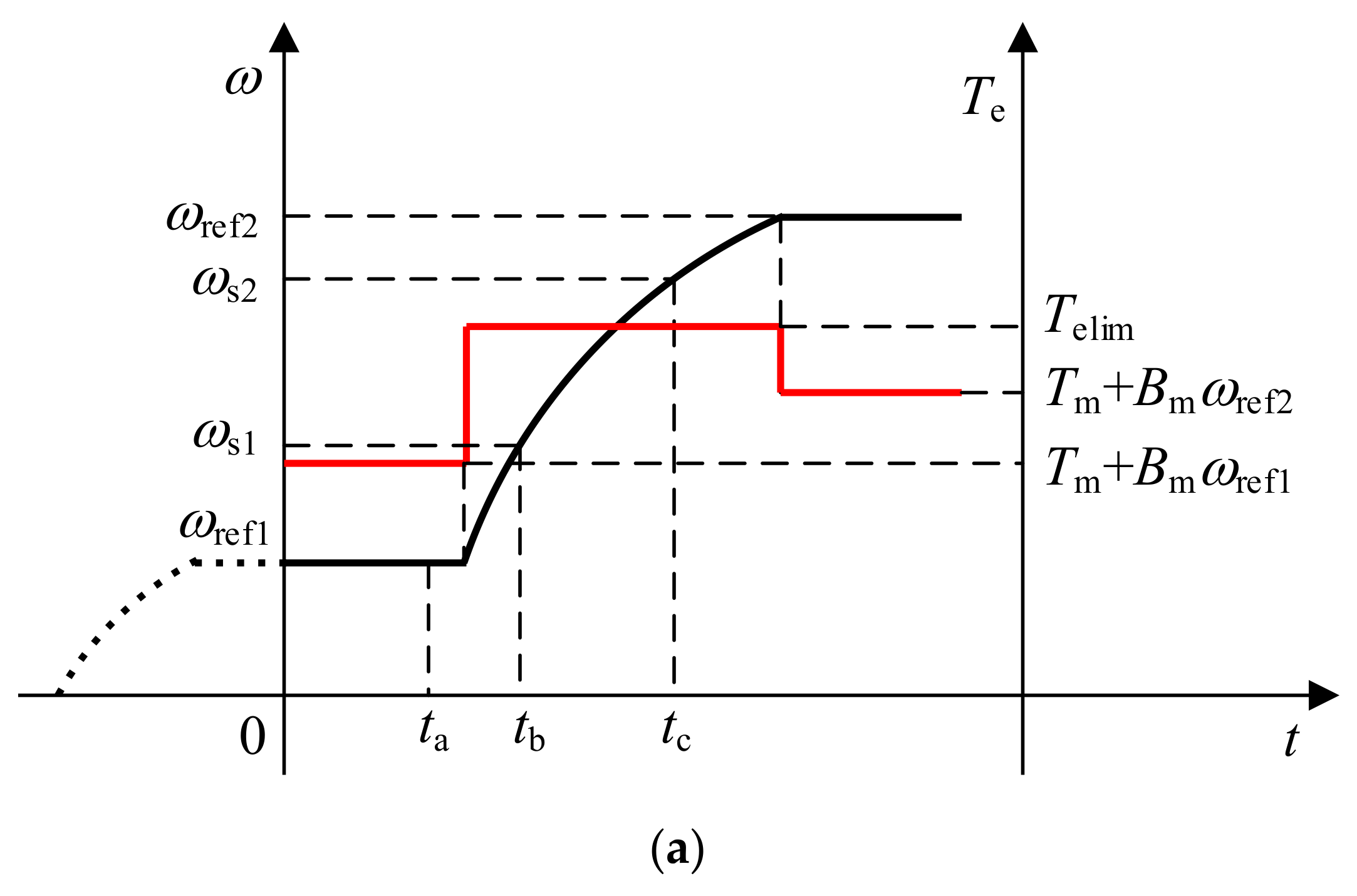
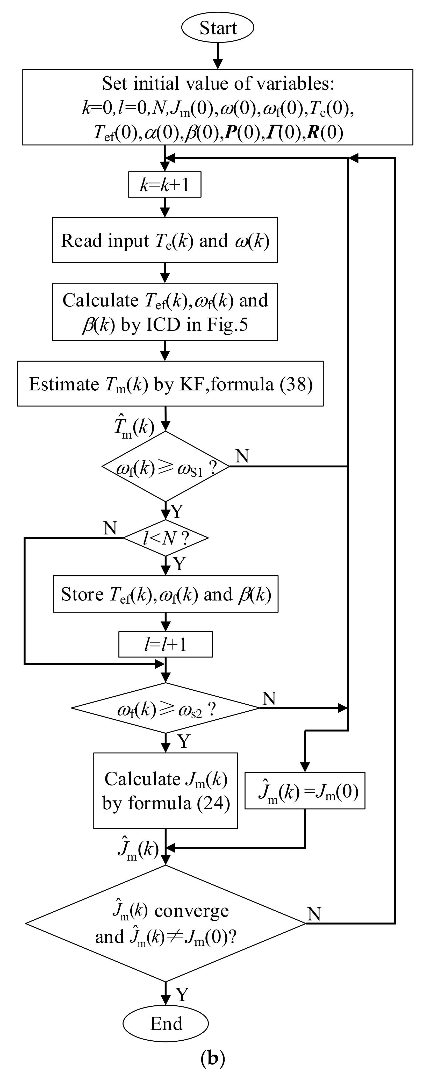
In light of the shortcomings of the above acceleration deceleration method, the identification accuracy of the moment of inertia was improved from three aspects in this paper. First, viscous friction torque is considered in the calculation of inertia torque. Second, the instantaneous angular acceleration of several moments can be calculated by the integral chain differentiator. Thus, it is avoided to replace the instantaneous angular acceleration at a certain time with the average angular acceleration in a certain period of time. Then, the error function is constructed with the principle of the least square sum of errors, and the moment of inertia is solved by optimizing the error function. Third, the integral chain differentiator is used to suppress the noise in the sampling signal so as to reduce the influence of measurement noise on the identification results. The schematic diagram of the identification method is shown in Figure 3.
Figure 3a shows the experimental process of the proposed moment of inertia identification method. ωref1 and ωref2 are the reference values of angular velocity in steady-state operation before and after speed increase, respectively. tb and tc are two different moments in the acceleration process, and the angular velocities at the corresponding time are ωs1 and ωs2, respectively. Figure 3b shows the identification process of the moment of inertia, Tef and ωf are electromagnetic torque and angular velocity signals obtained after noise suppression; Jm(0) is the initial value of moment of inertia. N groups of stored data between tb and tc participate in each calculation of the moment of inertia. The error function designed according to the least square sum of errors is shown as Equation (21):
F ( J m ) = l = 0 N 1 [ u ( l ) β ( l ) J m ] 2 u ( l ) = T ef ( l ) B ^ m ω f ( l ) T ^ m
where u/Nm is defined as the inertia torque in this paper and β/rads−2 is the angular acceleration.
Jm, the minimum value of the error function, is the identification value of the moment of inertia. The minimum point of the objective function is determined by the derivative of the objective function. Let the derivative of (21) with respect to Jm be 0. Equation (22) can be obtained as
d F ( J m ) d J m = 2 l = 0 N 1 [ β ( l ) J m u ( l ) ] β ( l ) = 0
From (22), the estimated moment of inertia can be expressed as Equation (23):
J ^ m = l = 0 N 1 u ( l ) β ( l ) l = 0 N 1 β ( l ) 2
It can be seen from Equations (21) and (23) that viscous friction coefficient, electromagnetic torque, and angular velocity after noise suppression, angular acceleration, and total load torque are required to calculate the moment of inertia. The solution methods of each parameter are introduced below.

2.2.2. Estimation of Viscous Friction Coefficient and Coulomb Friction Torque

Friction torque causes loss, which affects the efficiency of the motor during operation. These losses can be relatively important, especially for actuators running at high speed [16] for oil compensated motors used for a marine environment [17], more generally for actuators coupled with viscous loads such as the ones used, for example, for underground robotics [18]. In addition, moment of inertia identification also depends on the value of the friction torque. Therefore, it is necessary to estimate the viscous friction coefficient and Coulomb friction torque.
The angular acceleration is zero when the motor rotates at a constant speed and the load torque is zero. Then, Equation (24) can be obtained as
T e = B m ω + sgn ( ω ) C m
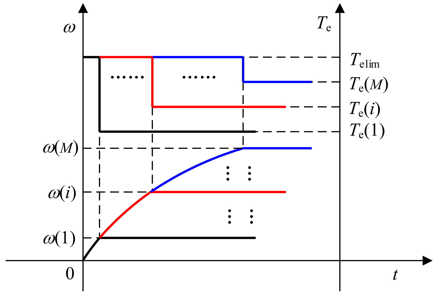
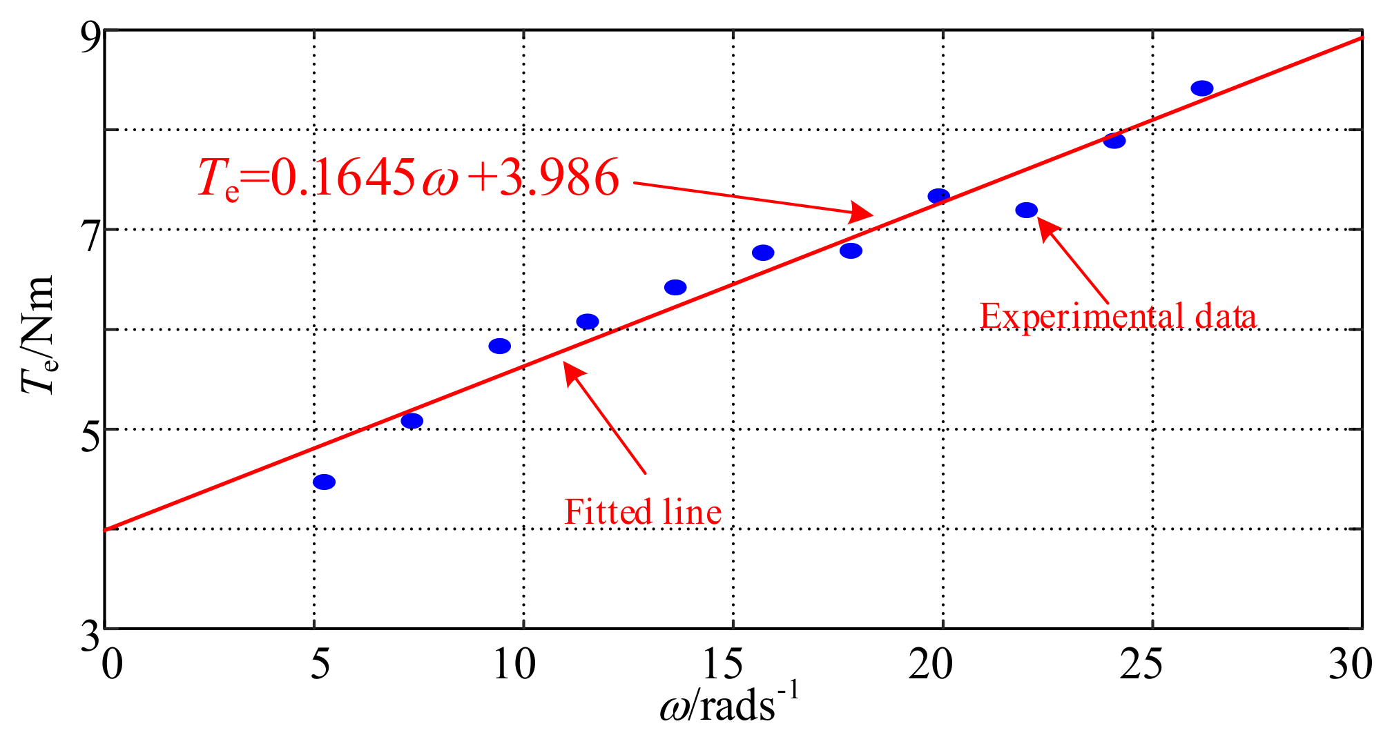
Under the condition that the rotation direction of the motor is constant, the relationship between the electromagnetic torque Te and the angular velocity ω is linear when the motor runs stably at different speeds. Design M experiments, and measure the electromagnetic torque Te(i) and angular velocity ω(i) during steady-state operation of the motor during the i-th (i = 1, …, M) experiment, as shown in Figure 4. The slope and intercept of the fitted line are the viscous friction coefficient and Coulomb friction torque, respectively. Telim is the limit amplitude of the electromagnetic torque. According to the principle of least squares, Equation (25) should be taken as the minimum with Bm and Cm.
G ( B m , C m ) = i = 1 M ( T e ( i ) B m ω ( i ) C m ) 2
By using the method of the partial derivative of function to find the extremum, Equation (26) can be obtained as
G B m = 2 i = 1 M ( T e ( i ) B m ω ( i ) C m ) = 0 G C m = 2 i = 1 M ( T e ( i ) B m ω ( i ) C m ) ω ( i ) = 0
From Equation (26), the estimated values of the viscous friction coefficient and Coulomb friction torque are shown in Equation (27):
B ^ m = M i = 1 M T e ( i ) ω ( i ) i = 1 M T e ( i ) i = 1 M ω ( i ) M i = 1 M ω 2 ( i ) ( i = 1 M ω ( i ) ) 2 C ^ m = i = 1 M T e ( i ) i = 1 M ω 2 ( i ) i = 1 M T e ( i ) ω ( i ) i = 1 M ω ( i ) M i = 1 M ω 2 ( i ) ( i = 1 M ω ( i ) ) 2

2.2.3. Sampling Noise Suppression and Instantaneous Angular Acceleration Solution

In the motor control system, it will inevitably bring a large error to the approximate estimation of angular acceleration by using difference instead of differential because the speed sampling signal is discontinuous and contains noise. State observer and Kalman filter can be used to estimate differential signals and suppress noise effectively, but it is inconvenient to adjust their parameters. Therefore, in this paper, the integral chain differentiator was introduced to suppress the noise in the electromagnetic torque and speed signals and realize the solution of the instantaneous angular acceleration. The integral chain differentiator can effectively suppress the signal noise while solving the differential of the signal, and has the advantage of convenient parameter adjustment at the same time.
In order to obtain better noise suppression effect, in this paper, the third order integral chain differentiator was used to obtain the signal of angular velocity and electromagnetic torque after noise suppression and angular acceleration signal. According to [19], the third-order integral chain differentiator can be expressed as Equations (28)–(30):
d ω f ( t ) d t = β ( t )
d β ( t ) d t = α ( t )
d α ( t ) d t = a 1 ε 3 [ ω ( t ) ω f ( t ) ] a 2 ε 2 β ( t ) a 3 ε α ( t )
where angular velocity ω(t)/rads−1 is the input signal of differentiator; ωf(t)/rads−1 and β(t)/rads−2 are the angular velocity and angular acceleration output by the integral chain differentiator, respectively; α(t)/rads−3 is the differential of angular acceleration; ε is a sufficiently small positive value; and a1, a2, and a3 are the system parameters.
In order to meet the system stability requirements, parameters a1, a2, a3 should meet the requirements of Equation (31) [19].
a j > 0 , j = 1 , 2 , 3 . a 2 a 3 > a 1
The structure of the integral chain differentiator to solve the angular acceleration and the angular velocity signal after noise suppression is shown in Figure 5.
The noise of the signal exists in the input term ω(t). From Figure 5, it can be seen that the input term only exists in the lowest differential Equation (30). β(t) and ωf(t) are obtained by two and three times integral of dα(t)/dt, respectively. The integral is not sensitive to noise. Therefore, the integral chain differentiator structure shown in Figure 5 can effectively suppress the noise in the sampling signal. The following theoretical analysis was carried out.
Through Laplace transformation of (28)–(30), the result is as Equation (32):
ω f ( s ) ω ( s ) = a 1 ε 3 s 3 + a 3 ε 2 s 2 + a 2 ε s + a 1
where ωf(s) and ω(s) are the Laplace transform forms of ωf(t) and ω(t), respectively.
The amplitude frequency characteristics and phase frequency characteristics corresponding to (32) are shown in Equation (33):
A ( υ ) = 1 1 + τ 1 ε 6 υ 6 + τ 2 ε 4 υ 4 + τ 3 ε 2 υ 2 ϕ ( υ ) = arctan ε ( a 2 υ ε 2 υ 3 ) a 1 a 3 ε 2 υ 2
where υ is the frequency of the input signal and τm(m = 1,2,3) is shown in Equation (34):
τ 1 = 1 a 1 2 τ 2 = a 3 2 2 a 2 a 1 2 τ 3 = a 2 2 2 a 1 a 3 a 1 2
By analyzing the amplitude phase frequency characteristics, the following conclusions can be obtained.
(1)
It can be obtained that A(υ) ≈ 1 and ϕ(υ) ≈ 0, when ε→0 and the frequency of the input signal is not large enough. Therefore, ωf(t) can track the original signal ω(t) accurately. Therefore, combined with (28), it can be considered that ωf(t) and β(t) approximately equal the angular velocity and its differential signal, respectively;
(2)
In general, the frequency of noise in the input signal is far greater than that of the ideal input signal. From (33), when the input signal frequency is very high, there is A(υ) << 1, indicating that the integrator chain differentiator can suppress the high-frequency noise in the input signal;
(3)
According to (33), when the parameters a1, a2, and a3 are determined, the tracking performance and noise suppression performance of the integral chain differentiator are only related to ε and the parameter adjustment is convenient. The smaller the value of ε, the better the tracking effect, but the ability of suppressing high-frequency noise will become worse; the larger the value of ε, the worse the tracking performance of ωf(t) will be, but the ability to resist high-frequency interference will be stronger. Therefore, it is necessary to select a suitable ε value to balance the tracking performance and anti-interference performance of the differentiator.
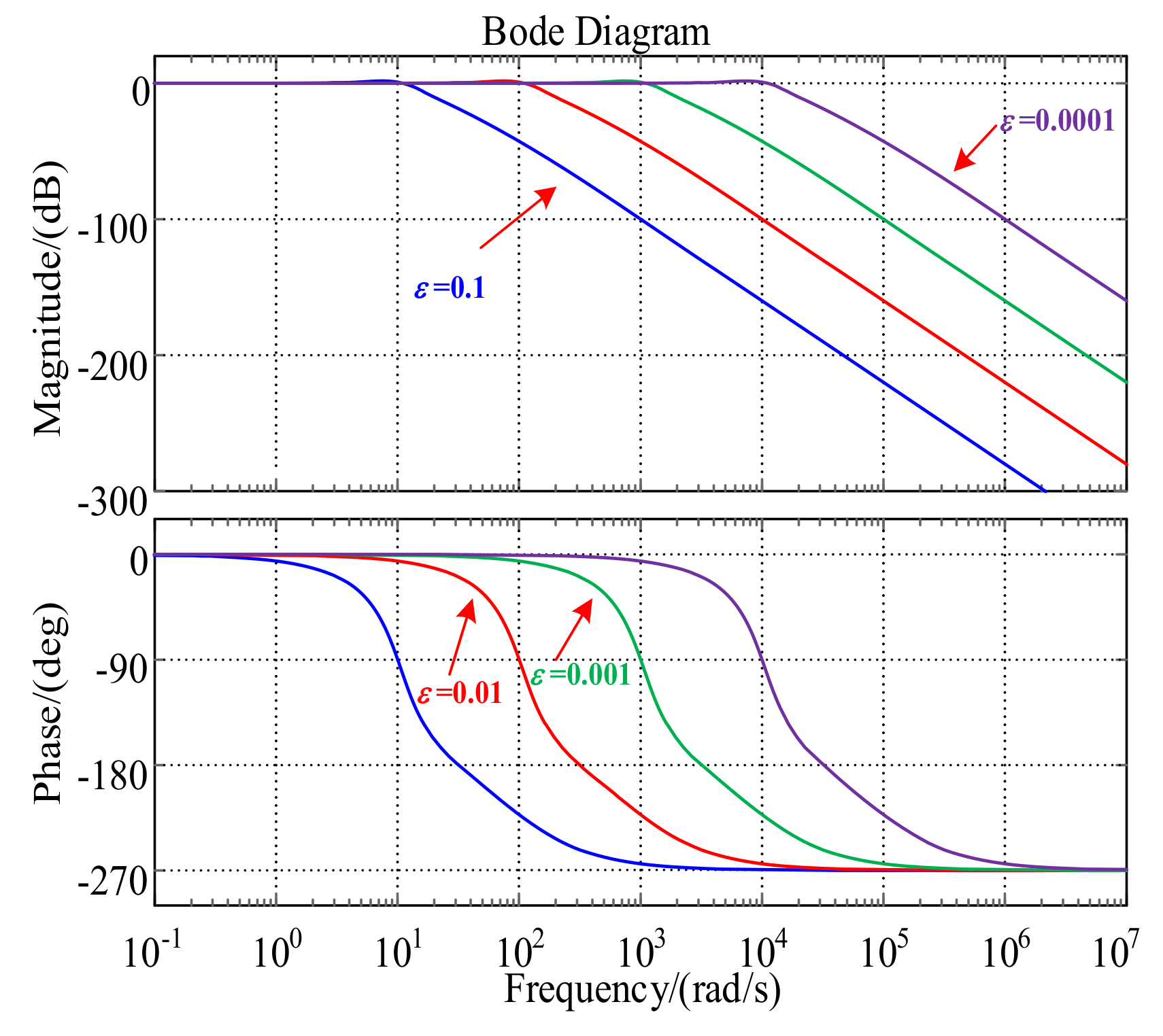
In order to observe the amplitude frequency and phase frequency characteristics of Equation (32) intuitively, a corresponding bode diagram was made, as shown in Figure 6, where a1 = a2 = a3 = 10 was taken to satisfy the conditions shown in Equation (31). The values of ε were 0.1, 0.01, 0.001, and 0.0001, respectively.
It can be seen from Figure 6 that after the parameters a1, a2, and a3 were determined, the influence of parameter ε on the tracking and noise suppression performance of the integrator chain differentiator conformed to the above analysis. Adjusting the parameter ε can change the tracking and noise suppression ability of the integrator chain differentiator. In the same way, Tef can be obtained.

2.2.4. Estimation of Total Load Torque

The motor angular speed ω and the total load torque Tm were selected as the state variables. Due to the short sampling time, the value of Tm can be considered unchanged in a sampling period, which is, dTm/dt = 0. Thus, the state equation of the motor is expressed by Equation (35):
d ω d t d T m d t = B m J m 1 J m 0 0 ω T m + 1 J m 0 T ef
By using the forward Euler method and substituting difference for differential, (35) can be discretized as Equation (36):
x ( k ) = A x ( k 1 ) + B u ( k 1 ) + w ( k ) y ( k ) = H x ( k ) + η ( k )
where A = 1 T s B m J m T s J m 0 1 ; B = T s J m 0 ; H = [1 0] is the output matrix; x = [ω Tm]T is the state variable; u = Tef is the input variable; and y = ω is the output variable; and w = [wω wT]T and η = [ηω] are system noise and measurement noise, respectively, and their covariance matrices are Γ and R, respectively.
In fact, wω is related to wT. Therefore, Γ is not a diagonal matrix, strictly. However, its non-diagonal elements are difficult to determine, and the influence of the non-diagonal elements on the state estimation of the Kalman filter can be ignored. Therefore, it can be considered that the non-diagonal elements of Γ are zero [5].
Under such conditions, Equation (37) can be obtained as
Γ = Γ ω 0 0 Γ T R = [ R ω ]
where Γω, ΓT, and Rω are the variances of wω, wT, and ηω, respectively.
With (35) and (36), the Kalman filter algorithm is as Equation (38) [1].
x ^ ( k | k 1 ) = A x ^ ( k 1 ) + B u ( k 1 ) P ( k | k 1 ) = A P ( k 1 ) A T + Γ ( k ) K ( k ) = P ( k | k 1 ) H T [ H P ( k | k 1 ) H T + R ( k ) ] 1 x ^ ( k ) = x ^ ( k | k 1 ) + K ( k ) [ ω f H x ^ ( k | k 1 ) ] P ( k ) = [ I K ( k ) H ] P ( k | k 1 )
where x ^ ( k | k 1 ) and P(k|k − 1) are the k-th prediction value and prediction error covariance matrix of state variables, respectively; x ^ ( k ) and P(k) are the k-th estimation value of state variables and the estimation error covariance matrix, respectively; K(k) is the Kalman gain; and I is the identity matrix.

2.2.5. Simulation Results

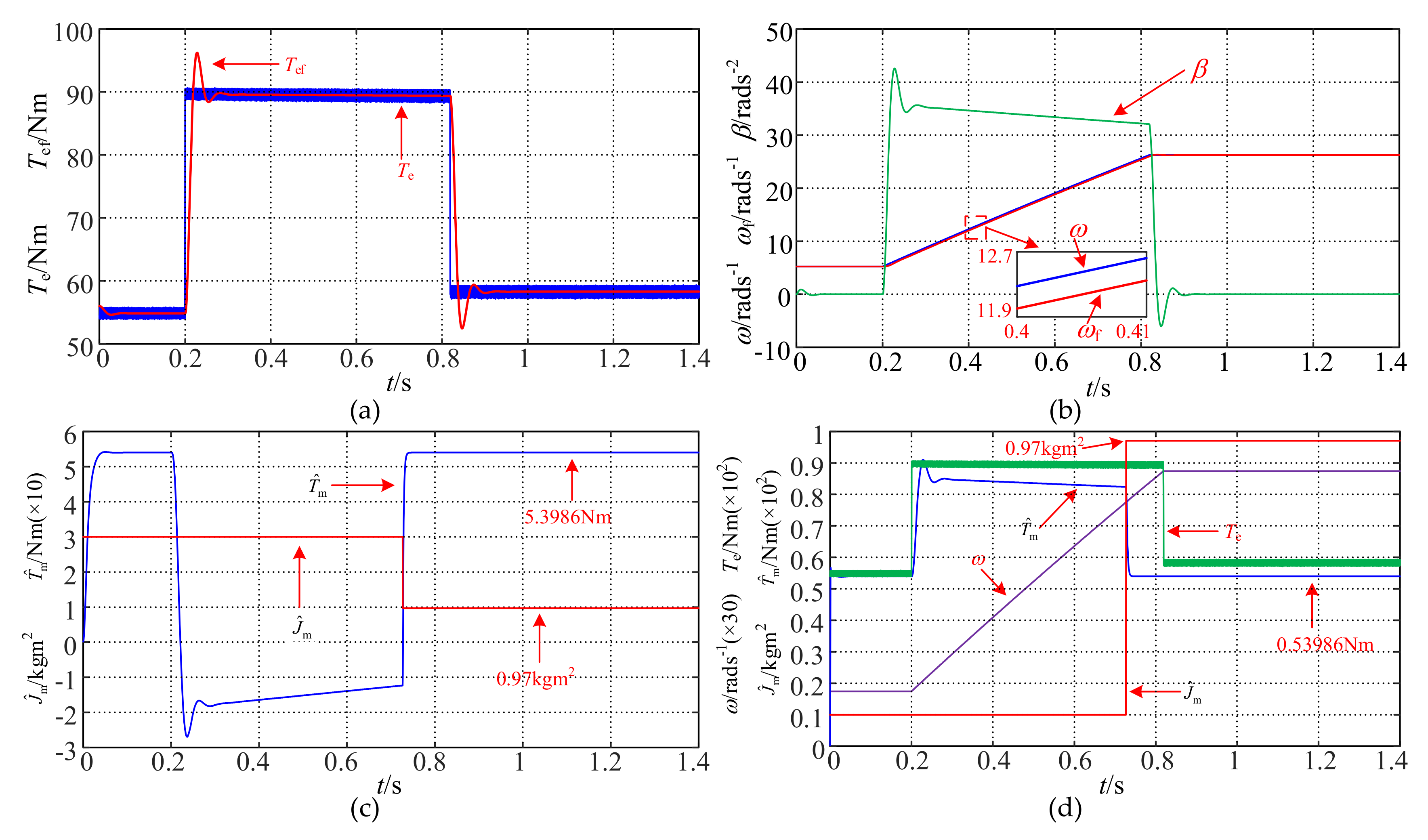
In the simulation, the motor parameters are shown in Table 1, where the viscous friction coefficient was 0.1645 Nms/rad, and the Coulomb friction torque was 3.986 Nm. The parameters of the Kalman filter were set as Γ = diag(0.00001,2), R = [2], and the parameters of the integral chain differentiator were a1 = a2 = a3 = 10, ε = 8 × 10⁻³. The total load torque Tm was 53.986 Nm when a load torque of 50 Nm was applied to the motor. The initial speed of the motor was 50 rmin−1. The motor will speed up to 250 rmin−1 after stable operation. The initial moment of inertia of the motor was set to 3 kg m2 and 0.1 kg m2. The waveform of the simulation and identification process is shown in Figure 7.
It can be seen from Figure 7 that the overshoot occurs at the torque step when the integral chain differentiator tracks the electromagnetic torque. In order to ensure the accuracy of the identification results, the data in the overshoot phase should be avoided when the moment of inertia is identified with the data of the acceleration stage. At the same time, it can be seen from Figure 7b that when the integral chain differentiator tracks the angular velocity, the tracking curve has a slight lag compared with the actual angular velocity curve in the acceleration stage, but the phase lag almost has no impact on the identification results since the electromagnetic torque is approximately constant in the acceleration stage. It can be seen from the acceleration curve that the angular acceleration of the motor gradually decreased from 35.5 rads−2 to 31.2 rads−2 in the acceleration stage. The variable angular acceleration of the motor is one of the error sources of the traditional acceleration deceleration method and the improved acceleration deceleration method.
The identification values of the moment of inertia and total load torque with the traditional acceleration deceleration method, the improved acceleration deceleration method and the proposed method were calculated, respectively, and the identification error was calculated. The calculation results are listed in Table 3. The total load torque identification error eT can be calculated by Equation (39):
e T = | T ^ m T m | T m
The simulation results show that compared with the traditional acceleration deceleration method and the improved acceleration deceleration method, the inertia identification accuracy of proposed method was greatly improved, and the total load torque was accurately estimated.

3. Experimental Results

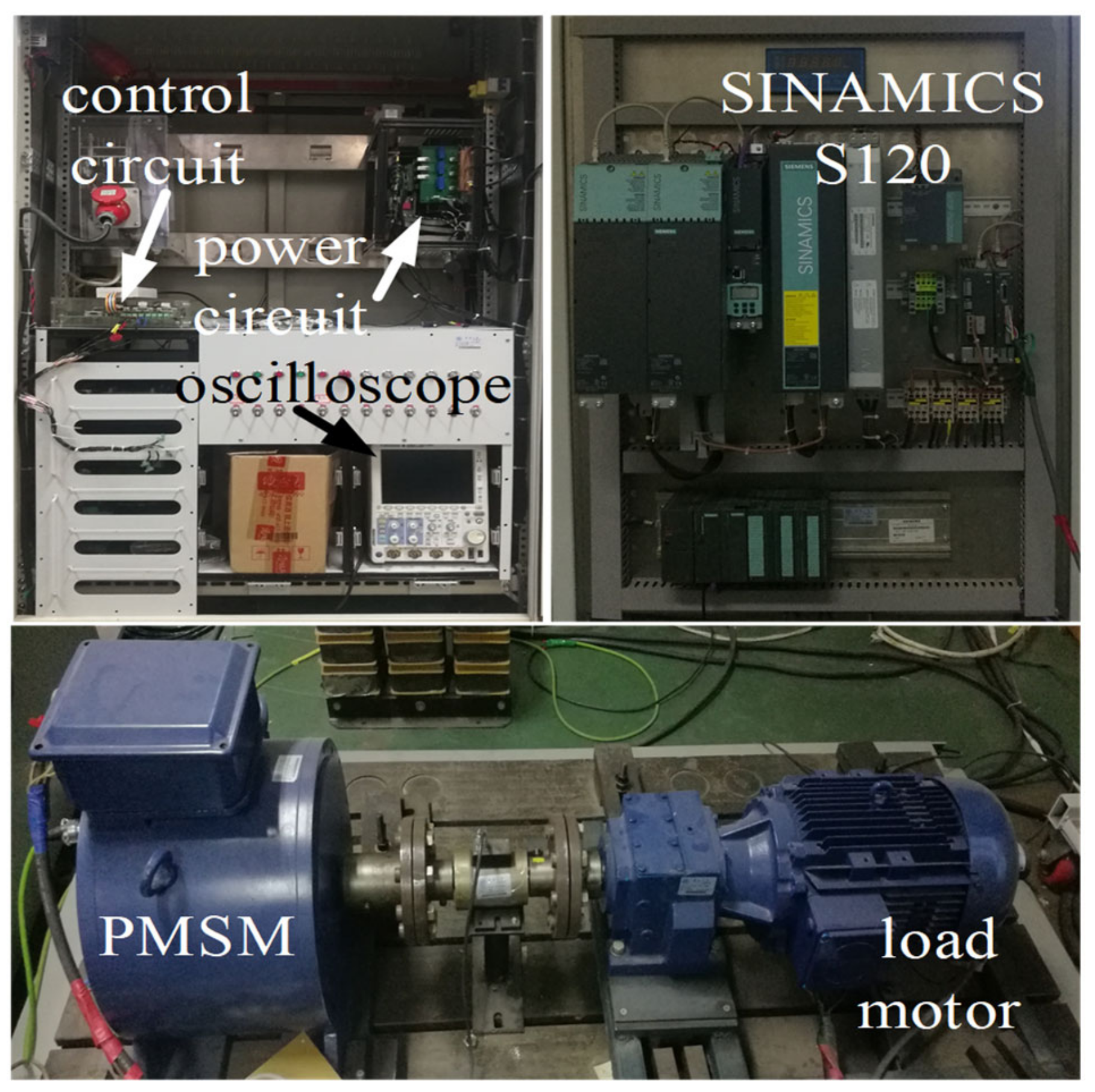
The experimental platform is shown in Figure 8. The experimental motor was a 6 kW surface mounted PMSM, and its parameters are shown in Table 1. The control system of PMSM adopted a TMS320F28335 DSP chip and EP3C40Q240C8N FPGA as the control core. The load motor was an 11.2 kW induction motor, which was connected with PMSM through the reduction gear box. The load motor was controlled by the SINAMICS S120 series frequency converter by the Siemens company. The sampling period of the ADC module was 100 μs and the sampling period of the oscilloscope was 1.6 μs.

3.1. Identification of Viscous Friction Coefficient and Coulomb Friction Torque

According to the method described in Section 2.2, M (value 11) experiments were carried out. The electromagnetic torque and angular velocity data of the motor during steady-state operation were collected during each experiment to identify the viscous friction coefficient and Coulomb friction torque of the tested motor system. The experimental results are shown in Figure 9.
It can be seen from the figure that the linear relationship between the electromagnetic torque and the angular velocity of the motor is presented in steady-state operation at different speeds when the angular speed range is 5.24–26.18 rads−1 and the load torque is zero. Therefore, the slope and intercept of the fitting line can be used to express the viscous friction coefficient and Coulomb friction torque, which are 0.1645 Nms/rad and 3.986 Nm, respectively.

3.2. Experimental Results of Moment of Inertia and Total Load Torque Identification When TL = 50 Nm, TL = 100 Nm

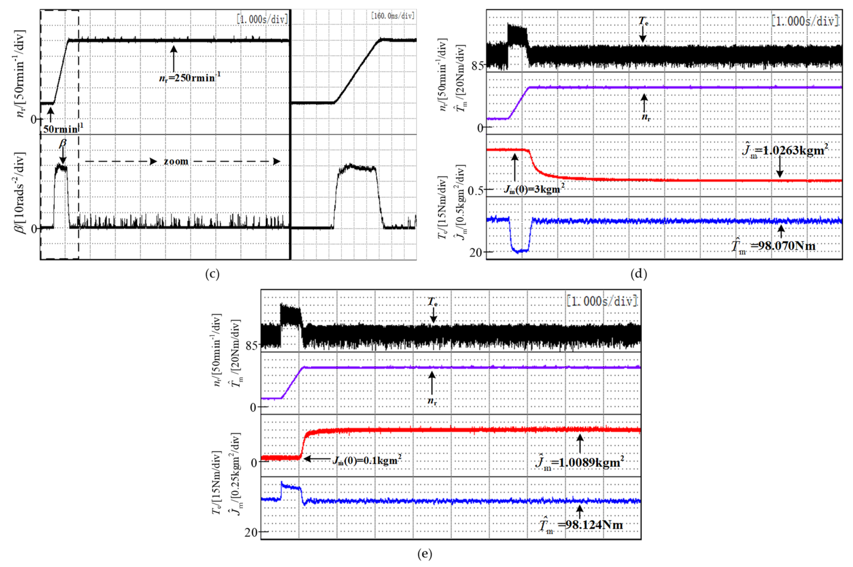
The parameters of the Kalman filter and integral chain differentiator are consistent with the simulation. During the experiment, the motor was loaded and operated stably at 50 rmin−1, then the reference signal of motor speed was stepped to 250 rmin−1. In the process of increasing speed from 50 rmin−1 to 250 rmin−1, part data of the acceleration stage were stored. In the experiment, the moment of inertia identification was started when the speed nf after noise suppression reached 219.63 rmin−1 (ωs2 = 23 rads−1). The load torque was set to 50 Nm and 100 Nm, respectively. The experimental results are shown in Figure 10 and Figure 11. The initial values of the moment of inertia in each group of experiments were set as 3 kg m2 and 0.1 kg m2, respectively. In the figure, ia, ib, and ic are the three-phase current of the motor stator, respectively, and StdDev represents the standard deviation of the corresponding physical quantity when the motor operates at steady-state, so as to judge the noise suppression ability of the integral chain differentiator. The electromagnetic torque Te is calculated by Equation (12), and the speed nr is obtained by DSP processing the pulse signal of photoelectric encoder.
The standard deviation of electromagnetic torque sample signal is calculated by Equation (40):
E ( T e ) = 1 X i = 1 X T e ( i ) S t d D e v = i = 1 X ( T e ( i ) E ( T e ) ) 2 X 1
where E is the sample mean of the correlation quantity and X is the sample number of the sample signal. In the same way, the standard deviation of Tef can be calculated.

4. Discussion

The experimental results showed that the standard deviation of the electromagnetic torque signal was 7.7562 Nm and 7.6584 Nm, respectively when the motor was loaded with 50 Nm and 100 Nm while the standard deviation of the signal after noise suppression by the integral chain differentiator was 1.5570 Nm and 2.0887 Nm, respectively. It showed that the integral chain differentiator could effectively suppress the noise in the electromagnetic torque signal, which is conducive to the reduction in identification error and the fluctuation of identification results. The integral chain differentiator had no obvious effect on the noise suppression of the speed signal due to the other speed filtering algorithms included in the algorithm. From the acceleration waveform in Figure 10c and Figure 11c, it can be seen that the angular acceleration first reached the maximum value in the acceleration stage, and then decreased slowly, which was similar to the simulation results. Therefore, it will bring about a large error when the angular acceleration is seen as a constant value to identify the moment of inertia in the process of acceleration. Additionally, it shows the rationality to solve the real-time angular acceleration and inertia torque with the proposed method in this paper. Table 4 lists the identification values and errors of the traditional acceleration deceleration method, the improved acceleration deceleration method, and the method proposed in this paper.
It can be seen that the identification error of the proposed method slightly increased with the increase of load torque, but its identification accuracy was still higher than that of the existing acceleration deceleration identification methods, and the total load torque could be accurately estimated.

5. Conclusions

In this paper, the error analysis of the existing acceleration deceleration moment of the inertia identification method was carried out. It showed that the error of the moment of inertia came from the measurement noise, inaccurate calculation of the instantaneous angular acceleration, and the corresponding moment of inertia torque in the existing identification method. The correctness of the error analysis was verified by simulation. In light of the shortcomings of the existing methods and the influence of sampling noise on the identification results in the experimental process, the inertial torque calculation, instantaneous angular acceleration calculation, and sampling noise suppression were considered in this paper. Based on the unsimplified PMSM model, a method based on the Kalman filter and integral chain differentiator was established to identify the moment of inertia. Simulation results showed that the proposed identification method could accurately identify the moment of inertia and total load torque without noise. In the experiment, the viscous friction coefficient was first identified by the experiments. It showed that the viscous friction coefficient is approximately a constant in a small speed range, and the speed range in the moment of inertia identification experiment was the same as that of the motor in the experiment of identifying the viscous friction coefficient. Therefore, the value of the inertia torque will be more accurate when the viscous friction coefficient is applied to the calculation of the inertia torque. By comparing the waveform and standard deviation of electromagnetic torque and the electromagnetic torque after noise suppression by the integral chain differentiator, it can be found that a satisfactory noise suppression effect can be obtained by setting appropriate parameters of an integral chain differentiator, which is conducive to reducing identification error and identification result fluctuation. Furthermore, it can be seen from the experimental waveform of angular acceleration that the integral chain differentiator has better performance in solving the instantaneous angular acceleration, which is conducive to further improving the identification accuracy. The application of the Kalman filter means that the method does not need to consider the load condition. At the same time, the Kalman filter has a faster convergence speed when the Kalman filter parameters are set properly, which improves the practicability of the method. In conclusion, the proposed method can effectively identify the moment of inertia and accurately estimate the total load torque with or without noise.

Author Contributions

Conceptualization, Validation and Writing—original draft, C.J.; Formal analysis, S.L.; Funding acquisition, T.S.; Software, C.J. and S.L.; Project administration, Y.Y. and Z.W.; Investigation, Y.Y. and L.G.; Writing–review & editing Y.Y., T.S., and S.L. All authors have read and agreed to the published version of the manuscript.

Funding

This research was funded by [Major Program of National Natural Science Foundation of China] grant number [51991384] and [National Key Research and Development Project of China] grant number [2019YFB1503703].

Institutional Review Board Statement

Not applicable.

Informed Consent Statement

Not applicable.

Data Availability Statement

Data available on request due to restrictions e.g., privacy or ethical. The data presented in this study are available on request from the corresponding author. The data are not publicly available due to the need for further research.

Conflicts of Interest

The authors declare no conflict of interest.

Nomenclature

a1, a2, a3system parameters of Integral Chain Differentiator
Bmviscous friction coefficient
CmCoulomb friction torque
eJmoment of inertia identification error
eTtotal load torque identification error
idcurrent of d-axis
iqcurrent of q-axis
Jmmoment of inertia
J ^ m identification value of moment of inertia
kiteration times of Kalman Filter
Ldinductance of d-axis
Lqinductance of q-axis
nnumber of segments in each ΔT
nrmotor speed
pnumber of pole-pairs of the motor
Rcovariance matrix of measurement noise
ttime variable
t1starting time of Δt
t2ending time of Δt
t20starting moment of the second ΔT
t2nending moment of the second ΔT
Teelectromagnetic torque
Te1electromagnetic torques corresponding to the first ΔT
Te2electromagnetic torques corresponding to the second ΔT
Te1(i)electromagnetic torque of the i-th sampling point in the first ΔT
Te2(i)electromagnetic torque of the i-th sampling point in the second ΔT
TLload torque
Tmtotal load torque
T ^ m estimated value of total load torque
Tssampling period
uinertia torque
α(t)differential signal of β
βangular acceleration
εa sufficiently small positive value
Γcovariance matrix of system noise
ωangular velocity
ω10starting angular velocity of the first ΔT
ω20starting angular velocity of the second ΔT
ω1nending angular velocity of the first ΔT
ω2nending angular velocity of the second ΔT
ω2angular velocity in the second ΔT
ω2iangular velocity of the i-th sampling point in the second ΔT
ω(t)input signal of Integral Chain Differentiator
ωf(t)angular velocity after noise suppression
ω(s)Laplace transform form of ω(t)
ωf(s)Laplace transform form of ωf(t)
ωξangular velocity at time ξ
ψdflux linkage of d-axis
ψfrotor flux linkage
ψqflux linkage of q-axis
Δttime length of the calculation interval in traditional acceleration deceleration method
ΔTtime length of the calculation interval in improved acceleration deceleration method
Δωangular velocity variation within Δt
Δω1angular velocity variation within the first ΔT
Δω2angular velocity variation within the second ΔT

References

  1. Yang, M.; Liu, Z.; Long, J.; Qu, W.; Xu, D. An Algorithm for Online Inertia Identification and Load Torque Observation via Adaptive Kalman Observer-Recursive Least Squares. Energies 2018, 11, 778. [Google Scholar] [CrossRef] [Green Version]
  2. Niu, L.; Xu, D.; Yang, M.; Gui, X.; Liu, Z. On-line Inertia Identification Algorithm for PI Parameters Optimization in Speed Loop. IEEE Trans. Power Electron. 2015, 30, 849–859. [Google Scholar] [CrossRef]
  3. Li, S.; Liu, Z. Adaptive Speed Control for Permanent-Magnet Synchronous Motor System with Variations of Load Inertia. IEEE Trans. Ind. Electron. 2009, 56, 3050–3059. [Google Scholar]
  4. Lee, K.B.; Yoo, J.Y.; Song, J.H.; Choy, I. Improvement of low speed operation of electric machine with an inertia identification using ROELO. IEE Proc. Electr. Power Appl. 2004, 151, 116–120. [Google Scholar] [CrossRef]
  5. Hong, S.J.; Kim, H.W.; Sul, S.K. A novel inertia identification method for speed control of electric machine. In Proceedings of the Conference of the IEEE Industrial Electronics Society, Taipei, Taiwan, 5–9 August 1996. [Google Scholar]
  6. Wei, C.; Zhaosheng, G.; Changliang, X.; Xin, G. Design of Adaptive Disturbance Observer for AC Servo System with Inertia Identification. Trans. China Electrotech. Soc. 2016, 31, 32–42. [Google Scholar]
  7. Xun, Q.; Wang, P.L.; Li, Z.X.; Cai, Z.D.; Qin, H.H. PMSM Parameters Identification Based on Recursive Least Square Method. Trans. China Electrotech. Soc. 2016, 31, 161–169. [Google Scholar]
  8. Choi, J.W.; Lee, S.C.; Kim, H.G. Inertia identification algorithm for high-performance speed control of electric motors. IEE Proc. Part B Electr. Power Appl. 2006, 153, 379–386. [Google Scholar] [CrossRef]
  9. Kim, S. Moment of Inertia and Friction Torque Coefficient Identification in a Servo Drive System. IEEE Trans. Ind. Electron. 2019, 66, 60–70. [Google Scholar] [CrossRef]
  10. Yao, L.; Qiu, X.; Wang, H.; Yan, Y. Methods of Inertia Identification for Permanent Magnet AC Servo System. Electr. Mach. Control Appl. 2013, 32, 29–35. [Google Scholar]
  11. Xu, H.; Zhu, X.; Li, Q.; Zhao, D.; Wang, L. Inertia Identification of Servo System Based on Improved Acceleration Deceleration Method. In Proceedings of the International Conference on Intelligent Human-machine Systems & Cybernetics, Hangzhou, China, 27–28 August 2016. [Google Scholar]
  12. Andoh, F. Moment of Inertia Identification Using the Time Average of the Product of Torque Reference Input and Motor Position. IEEE Trans. Power Electron. 2007, 22, 2534–2542. [Google Scholar] [CrossRef]
  13. Huynh, D.C.; Dunnigan, M.W. Parameter estimation of an induction machine using advanced particle swarm optimisation algorithms. IET Electr. Power Appl. 2010, 4, 748–760. [Google Scholar] [CrossRef]
  14. Liu, Z.H.; Wei, H.L.; Zhong, Q.C.; Liu, K.; Xiao, X.S.; Wu, L.H. Parameter Estimation for VSI-Fed PMSM Based on a Dynamic PSO With Learning Strategies. IEEE Trans. Power Electron. 2017, 32, 3154–3165. [Google Scholar] [CrossRef] [Green Version]
  15. Campos-Delgado, D.U.; Arce-Santana, E.R.; Espinoza-Trejo, D.R. Edge optimisation for parameter identification of induction motors. IET Electr. Power Appl. 2011, 5, 668–675. [Google Scholar] [CrossRef]
  16. Ciampolini, M.; Fazzini, L.; Berzi, L.; Ferrara, G.; Pugi, L. Simplified Approach for Developing Efficiency Maps of High-Speed PMSM Machines for Use in EAT Systems Starting from Single-Point Data. In Proceedings of the 2020 IEEE International Conference on Environment and Electrical Engineering and 2020 IEEE Industrial and Commercial Power Systems Europe (EEEIC/I&CPS Europe), Madrid, Spain, 9–12 June 2020. [Google Scholar]
  17. Allotta, B.; Costanzi, R.; Gelli, J.; Pugi, L.; Ridolfi, A. Design of a modular propulsion system for MARTA AUV. In Proceedings of the OCEANS 2015—Genova, Genoa, Italy, 18–21 May 2015. [Google Scholar]
  18. Pugi, L.; Berzi, L.; Savi, R.; Vita, V.; Grasso, F.; Delogu, M.; Boni, E. Electrification of an Innovative Directional Drilling Machine: Sizing and Design Models. In Proceedings of the 2020 AEIT International Annual Conference (AEIT), Catania, Italy, 23–25 September 2020. [Google Scholar]
  19. Wang, X.; Liu, J. Differentiator Design and Application—Signal Filtering and Differentiation, 1st ed.; Publishing House of Electronics Industry: Beijing, China, 2010; pp. 157–159. [Google Scholar]
Figure 1. Schematic diagram of the improved acceleration deceleration method.
Energies 14 00166 g001
Figure 2. Simulation waveform when Bm = 0.1645, Cm = 3.986.
Energies 14 00166 g002
Figure 3. Principle of method: (a) Experimental process of moment of inertia identification; (b) Identification flow chart.
Energies 14 00166 g003aEnergies 14 00166 g003b
Figure 4. Diagram of torque and speed waveform in the measurement of viscous friction coefficient and Coulomb friction torque.
Energies 14 00166 g004
Figure 5. Solution of angular acceleration signal and angular velocity signal after noise suppression.
Energies 14 00166 g005
Figure 6. Bode diagram of the integral chain differentiator.
Energies 14 00166 g006
Figure 7. Simulation results: (a) Electromagnetic torque waveform when Jm(0) = 3 kg m2; (b) Waveform of angular velocity and angular acceleration when Jm(0) = 3 kg m2; (c) Identification waveforms of moment of inertia and total load torque when Jm(0) = 3 kg m2; (d) Simulation and identification waveform when Jm(0) = 3 kg m2.
Energies 14 00166 g007
Figure 8. Experimental platform.
Energies 14 00166 g008
Figure 9. Fitting curve of viscous friction coefficient and Coulomb friction torque.
Energies 14 00166 g009
Figure 10. Experimental results with load torque of 50 Nm: (a) Three phase current and stator flux waveform; (b) Electromagnetic torque waveform; (c) Velocity and acceleration waveform; (d) Identification waveforms of moment of inertia and total load torque when Jm(0) = 3 kg m2; (e) Identification waveforms of moment of inertia and total load torque when Jm(0) = 0.1 kg m2.
Energies 14 00166 g010
Figure 11. Experimental results with a load torque of 100 Nm: (a) Three phase current waveform; (b) Electromagnetic torque waveform; (c) Velocity and acceleration waveform; (d) Identification waveforms of moment of inertia and total load torque when Jm(0) = 3 kg m2; (e) Identification waveforms of moment of inertia and total load torque when Jm(0) = 0.1 kg m2.
Energies 14 00166 g011aEnergies 14 00166 g011b
Table 1. Parameters of the motor.
ParameterQuantity
Rated Power6 kW
Rated Torque192 Nm
Rated Speed300 r/min
Rated Current11.8 A
Number of pole-pairs8
Stator resistance0.76 Ω
Stator inductance13 mH
Moment of inertia
(with loading motor)
0.97 kg m2
Table 2. Comparison of the simulation results of identification value and identification error.
Parameter ValueMethodΔtT)/s J ^ m / kg m 2 e J / %
Bm = 0.1645Conventional0.11.146118.15
0.21.156419.22
Cm = 3.986Improved0.020.98171.21
0.10.99022.08
Bm = 0Conventional0.10.98061.09
Cm = 0Improved0.020.96660.35
Bm = 0Conventional0.11.090512.42
Cm = 3.986Improved0.020.96390.63
Table 3. Comparison of the simulation results of the identification value and identification error.
MethodMoment of InertiaTotal Load Torque
J ^ m / kg m 2 e J / % T ^ m / Nm e T / %
Conventional1.154719.04--
Improved0.99802.89--
Proposed in this paper0.9700053.98600
Table 4. Comparison of the experimental results of the identification value and identification error.
Tm/NmMethodMoment of InertiaTotal Load Torque
J ^ m / kg m 2 e J / % T ^ m / Nm e T / %
53.986Conventional1.155819.15--
Improved1.04527.75--
Proposed in this paper1.01034.1551.3534.88
103.986Conventional1.075610.89--
Improved0.91315.87--
Proposed in this paper1.01764.9198.0975.66
Publisher’s Note: MDPI stays neutral with regard to jurisdictional claims in published maps and institutional affiliations.